Embed Size (px)
Citation preview
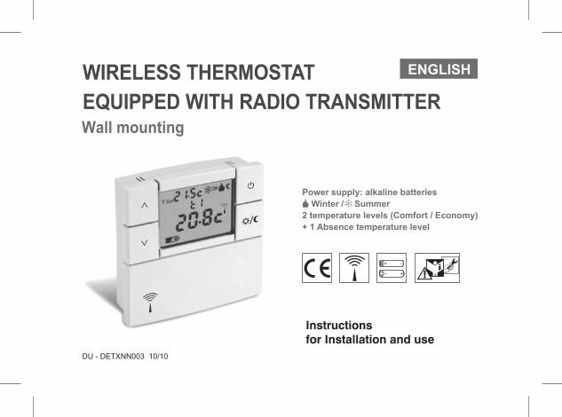
WIRELESS THERMOSTAT
Power supply: alkaline batteries
Winter / Summer
2 temperature levels (Comfort / Economy)
+ 1 Absence temperature level
EQUIPPED WITH RADIO TRANSMITTER
ENGLISH
Wall mounting
DU - DETXNN003 10/10
Instructions
for Installation and use
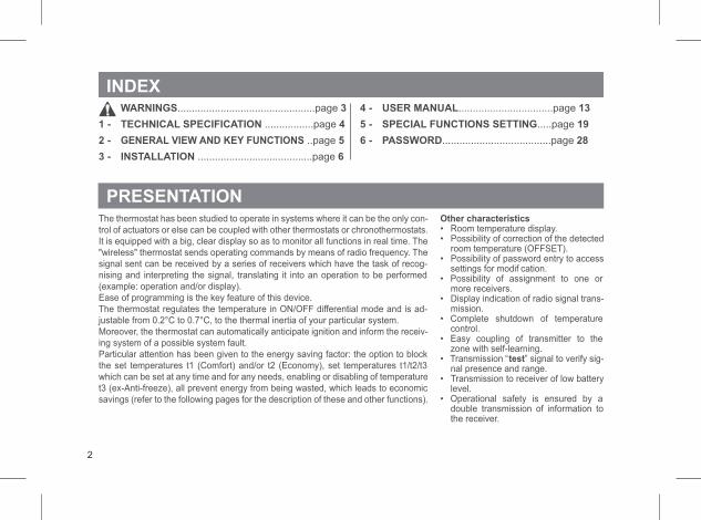
INDEX
PRESENTATIONThe thermostat has been studied to operate in systems where it can be the only con-
trol of actuators or else can be coupled with other thermostats or chronothermostats.
It is equipped with a big, clear display so as to monitor all functions in real time. The
"wireless" thermostat sends operating commands by means of radio frequency. The
signal sent can be received by a series of receivers which have the task of recog-
nising and interpreting the signal, translating it into an operation to be performed
(example: operation and/or display).
Ease of programming is the key feature of this device.
The thermostat regulates the temperature in ON/OFF differential mode and is ad-
justable from 0.2°C to 0.7°C, to the thermal inertia of your particular system.
Moreover, the thermostat can automatically anticipate ignition and inform the receiv-
ing system of a possible system fault.
Particular attention has been given to the energy saving factor: the option to block
the set temperatures t1 (Comfort) and/or t2 (Economy), set temperatures t1/t2/t3
which can be set at any time and for any needs, enabling or disabling of temperature
t3 (ex-Anti-freeze), all prevent energy from being wasted, which leads to economic
savings (refer to the following pages for the description of these and other functions).
Other characteristics• Room temperature display.• Possibility of correction of the detected
room temperature (OFFSET).• Possibility of password entry to access
settings for modif cation.• Possibility of assignment to one or
more receivers.• Display indication of radio signal trans-
mission.• Complete shutdown of temperature
control.• Easy coupling of transmitter to the
zone with self-learning.• Transmission “test” signal to verify sig-
nal presence and range.• Transmission to receiver of low battery
level.• Operational safety is ensured by a
double transmission of information tothe receiver.
WARNINGS................................................page 3
1 - TECHNICAL SPECIFICATION 4.................page
2 - GENERAL VIEW AND KEY FUNCTIONS ..page 5
3 - INSTALLATION 6........................................page
4 - USER MANUAL 13.................................page
5 - SPECIAL FUNCTIONS SETTING 19.....page
6 - PASSWORD 28......................................page
2
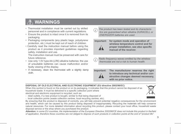
WARNINGS
• Thermostat installation must be carried out by skilled
personnel and in compliance with current regulations.
• Ensure the product is intact once it is removed from its
packaging.
• Packaging components (any plastic bags, polystyrene
protection, etc.) must be kept out of reach of children.
• Carefully read the instruction manual before using the
product as it provides important guidelines regarding
safety, installation and use.
The instruction manual must be preserved with care for
future reference.
• Use only 1.5V type AA (LR6) alkaline batteries; the use
of unsuitable batteries can cause malfunction and/or
faulty viewing of the display.
• If necessary, clean the thermostat with a slightly damp
cloth.
The product has been tested and its characteris-
tics are guaranteed when alkaline DURACELL or
ENERGIZER batteries are used.
Important: for system mode and operation of
wireless temperature control and for
proper installation, see also specific
manual of the receiver.
Radio frequency waves emitted by the wireless
thermostat are not a risk to human health.
Important: The manufacturer reserves the right
to introduce any technical and/or con-
structive changes deemed necessary,
with no prior notice.
DISPOSAL OF OLD ELECTRICAL AND ELECTRONIC EQUIPMENT (EU directive 2002/96/EC)When this symbol is found on the product or on its packaging, it indicates that this product cannot be disposed of ashousehold waste. It must be delivered to a specific collection point whereelectrical and electronic equipment is recycled, such as:- retail outlets, if a new product is bought, similar to that being disposed of- local collection points (waste collection centres, local recycling centres, etc).By ensuring that the product is disposed of correctly, you will help prevent potential negative consequences for the environmentand health, which can be caused by this product being disposed of inappropriately. Recycling the materials will help conservenatural resources. For more detailed information about recycling this product, please contact your local office, household wastedisposal service or the shop where you purchased the product.Attention: in some EU countries, the implementation of the European Directive 2002/96/CE does not include this product in thefieldof application, therefore these countries are not obliged to dispose of such products in collection points at the end of "product life".
3
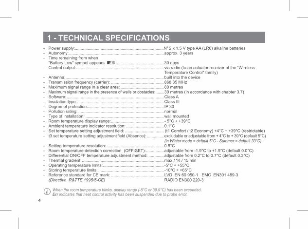
1 - TECHNICAL SPECIFICATIONS- Power supply:............................................................................N°2 x 1.5 V type AA (LR6) alkaline batteries- Autonomy:................................................................................. approx. 3 years- Time remaining from when
"Battery Low" symbol appears ......................................... 30 days- Control output:........................................................................... via radio (to an actuator receiver of the “Wireless
Temperature Control" family)- Antenna:.................................................................................... built into the device- Transmission frequency (carrier): ............................................. 868.35 MHz- Maximum signal range in a clear area: ..................................... 80 metres- Maximum signal range in the presence of walls or obstacles:........30 metres (in accordance with chapter 3.7)- Software:................................................................................... Class A- Insulation type:..........................................................................Class III- Degree of protection:................................................................. IP 30- Pollution rating: ......................................................................... normal- Type of installation: ...................................................................wall mounted- Room temperature display range:............................................. - 5°C ÷ +39°C- Ambient temperature indicator resolution: ................................ 0.1°C- Set temperature setting adjustment field: ................................. (t1 Comfort / t2 Economy) +4°C ÷ +39°C (restrictable)
- t3 set temperature setting adjustment field (Absence): ...............excludable or adjustable from + 4°C to + 39°C (default 5°C)
(in Winter mode = default 5°C - Summer = default 33°C)- Setting temperature resolution:................................................. 0.5°C- Room temperature detection correction (OFF-SET):............... adjustable from -1.9°C to +1.9°C (default 0.0°C)- Differential ON/OFF temperature adjustment method: ............. adjustable from 0.2°C to 0.7°C (default 0.3°C)- Thermal gradient: ......................................................................max 1°K / 15 min- Operating temperature limits:.................................................... -5°C ÷ +55°C- Storing temperature limits: ........................................................ -10°C ÷ +65°C- Reference standard for CE mark: ............................................. LVD EN 60 950-1 EMC EN301 489-3
(Directive R&TTE 1995/5-CE)- RADIO EN300 220-3
When the room temperature blinks, display range (-5°C or 39.9°C) has been exceeded.Err indicates that heat control activity has been suspended due to probe error.
4
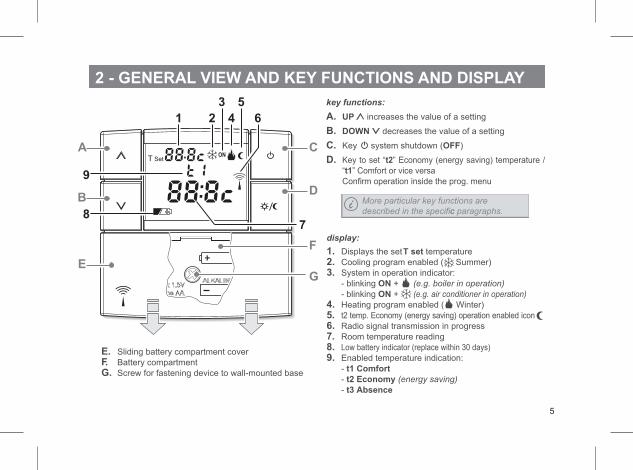
2 - GENERAL VIEW AND KEY FUNCTIONS AND DISPLAY
key functions:
A. UP increases the value of a setting
B. DOWN decreases the value of a setting
C. Key system shutdown ( )OFF
D. Key to set “t2” Economy (energy saving) temperature /
“ ” Comfort or vice versat1
Confirm operation inside the prog. menu
display:
1. Displays the set temperatureT set
2. Cooling program enabled ( Summer)
3. System in operation indicator:
- blinking ON + (e.g. boiler in operation)
- blinking +ON (e.g. air conditioner in operation)
4. Heating program enabled ( Winter)
5. t2 temp. Economy (energy saving) operation enabled icon
6. Radio signal transmission in progress
7. Room temperature reading
8. Low battery indicator (replace within 30 days)
9. Enabled temperature indication:
- t1 Comfort
- t2 Economy (energy saving)
- t3 Absence
E. Sliding battery compartment cover
F. Battery compartment
G. Screw for fastening device to wall-mounted base
More particular key functions are
described in the specificc paragraphs.
5
A
B
E
C
D
F
1 2
3
4
5
6
78
9
G
84
84 23
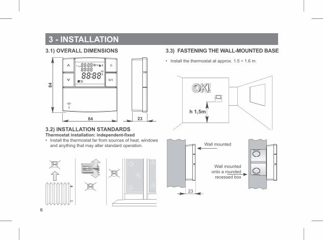
3 - INSTALLATION
3.1) OVERALL DIMENSIONS
3.2) INSTALLATION STANDARDSThermostat installation: independent-fixed
• Install the thermostat far from sources of heat, windows
and anything that may alter standard operation.
3.3) FASTENING THE WALL-MOUNTED BASE
• Install the thermostat at approx. 1.5 ÷ 1.6 m.
h 1,5m
23
Wall mounted
Wall mounted
onto a rounded
recessed box
6
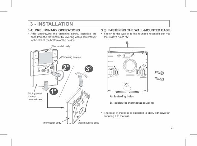
3.4) PRELIMINARY OPERATIONS• After unscrewing the fastening screw, separate the
base from the thermostat by levering with a screwdriver
in the slot at the bottom of the device.
3 - INSTALLATION
1°
2° 3°
Thermostat body Wall mounted base
Thermostat body
Sliding cover
battery
compartment
Fastening screws
3.5) FASTENING THE WALL-MOUNTED BASE• Fasten to the wall or to the rounded recessed box via
the relative holes “ ”.A
B
A
A A
A - fastening holes
B- cables for thermostat coupling
• The back of the base is designed to apply adhesive for
securing it to the wall.
7
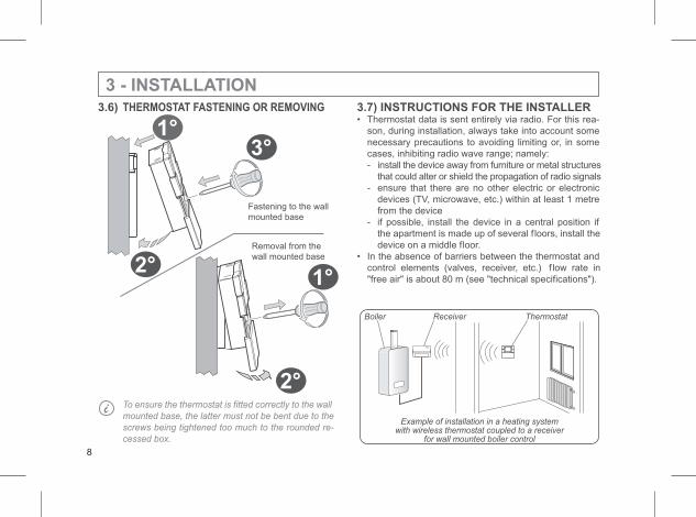
3 - INSTALLATION3.6) THERMOSTAT FASTENING OR REMOVING
To ensure the thermostat is fitted correctly to the wall
mounted base, the latter must not be bent due to the
screws being tightened too much to the rounded re-
cessed box.
Fastening to the wall
mounted base
Removal from the
wall mounted base
1°
2°
3°
1°
2°
3.7) INSTRUCTIONS FOR THE INSTALLER• Thermostat data is sent entirely via radio. For this rea-
son, during installation, always take into account some
necessary precautions to avoiding limiting or, in some
cases, inhibiting radio wave range; namely:
- install the device away from furniture or metal structures
that could alter or shield the propagation of radio signals
- ensure that there are no other electric or electronic
devices (TV, microwave, etc.) within at least 1 metre
from the device
- if possible, install the device in a central position if
the apartment is made up of several f loors, install the
device on a middle floor.
• In the absence of barriers between the thermostat and
control elements (valves, receiver, etc.) f low rate in
"free air" is about 80 m (see "technical specifications").
Example of installation in a heating systemwith wireless thermostat coupled to a receiver
for wall mounted boiler control
Boiler Receiver Thermostat
8
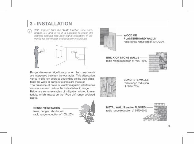
WOOD OR
PLASTERBOARD WALLS
radio range reduction of 10%÷30%
BRICK OR STONE WALLS
radio range reduction of 40%÷60%
CONCRETE WALLS
radio range reduction
of 50%÷70%
METAL WALLS and/or FLOORS
radio range reduction of 65%÷90%
3 - INSTALLATIONWith support from the “test” function (see para-graphs 3.9 and 3.10) it is possible to check theoptimal position (the best signal reception) in ad-vance for thermostat and receiver installation.
Range decreases significantly when the components
are interposed between the obstacles. This attenuation
varies in different degrees depending on the type of ma-
terial the walls or barriers to cross are made of.
The presence of noise or electromagnetic interference
sources can also reduce the indicated radio range.
Below are some examples of mitigation related to ma-
terials, which impact on the "Free air" range declared
above.
DENSE VEGETATION
trees, hedges, shrubs, etc.
radio range reduction of 10%¸25%
9
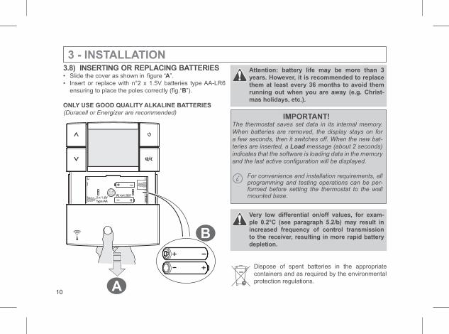
3 - INSTALLATION3.8) INSERTING OR REPLACING BATTERIES• Slide the cover as shown in figure “A”.
• Insert or replace with n°2 x 1.5V batteries type AA-LR6
ensuring to place the poles correctly (fig.“B”).
ONLY USE GOOD QUALITY ALKALINE BATTERIES
(Duracell or Energizer are recommended)
Attention: battery life may be more than 3
years. However, it is recommended to replace
them at least every 36 months to avoid them
running out when you are away (e.g. Christ-
mas holidays, etc.).
Very low differential on/off values, for exam-
ple 0.2°C (see paragraph 5.2/b) may result in
increased frequency of control transmission
to the receiver, resulting in more rapid battery
depletion.
Dispose of spent batteries in the appropriate
containers and as required by the environmental
protection regulations.
IMPORTANT!The thermostat saves set data in its internal memory.
When batteries are removed, the display stays on for
a few seconds, then it switches off. When the new bat-
teries are inserted, a Load message (about 2 seconds)
indicates that the software is loading data in the memory
and the last active configuration will be displayed.
For convenience and installation requirements, allprogramming and testing operations can be per-formed before setting the thermostat to the wallmounted base.
A
B
10
3 - INSTALLATION
press simultaneously for 4 seconds
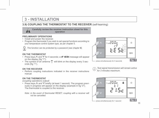
3.9) COUPLING THE THERMOSTAT TO THE RECEIVER (self-learning)
Carefully review the receiver instruction sheet for thisoperation
PRELIMINARY OPERATIONS• Install and power the receiver.• Program the thermostat if you wish to set special functions according to
your temperature control system type, as per chapter 5.
This function can be protected by a password (see chapter ).6
ON THE THERMOSTAT
• Press keys and for 4 seconds; a rF tESt message will appearon the display (fig."1").
• The symbol of an antenna will blink on the display every 3 sec-onds (fig.“1”).
ON THE RECEIVER• Perform coupling instructions indicated in the receiver instructions
manual.
ON THE THERMOSTAT(coupling operations output)
• Press keys and briefly (at least 1 second). The program previ-ously in progress will appear on the display (example in fig."2").The thermostat is coupled to the receiver.
Note: in the event of thermostat RESET, coupling with a receiver willnot be cancelled.
fig. 1
Test signal transmission will remain active
for 3 minutes maximum.
fig. 2press simultaneously for 1 second
11
press simultaneously for 7 seconds fig. 3
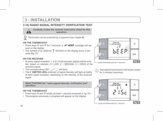
3.10) RADIO SIGNAL INTENSITY VERIFICATION TEST
Carefully review the receiver instruction sheet for thisoperation.
This function can be protected by a password (see chapter ).6
ON THE THERMOSTAT
• Press keys and for 7 seconds; a rF bEEP message will ap-
pear on the display.
• The symbol of an antenna will blink on the display every 3 sec-
onds (fig.“3”).
ON THE RECEIVER
• At every signal reception, 1, 2 or 3 brief acoustic signals will be emit-
ted, based on intensity (1= LOW, 2 = MEDIUM, 3 = HIGH) of the
received signal.
• The corresponding LED “ ” will blink.
• The 3 VMETER LEDs (indicator of signal intensity) will light up briefly
at each signal reception, depending on the intensity of the received
signal.
DEACTIVATING the "radio signal intensity verification test”operation
ON THE THERMOSTAT
• Press keys and briefly (at least 1 second) (example in fig.“4”).
• The program previously in progress will appear on the display.
3 - INSTALLATION
Test signal transmission will remain active
for 3 minutes maximum.
fig. 4press simultaneously for 1 second
12
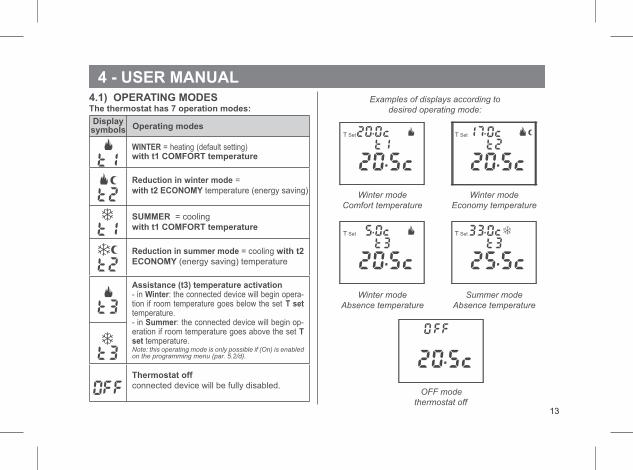
4 - USER MANUAL4.1) OPERATING MODESThe thermostat has 7 operation modes:
WINTER = heating (default setting)with t1 COMFORT temperature
Reduction in winter mode =
with t2 ECONOMY temperature (energy saving)
SUMMER = cooling
with t1 COMFORT temperature
Reduction in summer mode = cooling with t2
ECONOMY (energy saving) temperature
Assistance (t3) temperature activation- in Winter: the connected device will begin opera-tion if room temperature goes below the set T settemperature.- in Summer: the connected device will begin op-eration if room temperature goes above the set Tset temperature.Note: this operating mode is only possible if (On) is enabledon the programming menu (par. 5.2/d).
Thermostat off
connected device will be fully disabled.
Displaysymbols Operating modes
Examples of displays according to
desired operating mode:
Winter mode
Comfort temperature
Winter mode
Economy temperature
Winter mode
Absence temperature
Summer mode
Absence temperature
OFF mode
thermostat off13
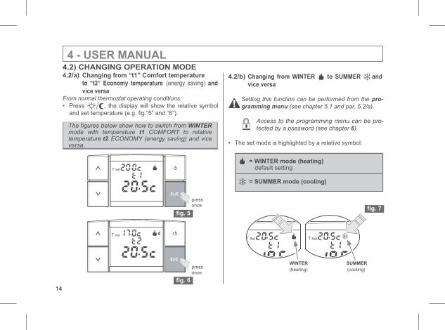
4.2/b) Changing from WINTER to SUMMER and
vice versa
Setting this function can be performed from the pro-
gramming menu (see chapter 5.1 and par. 5.2/a).
Access to the programming menu can be pro-
tected by a password (see chapter ).6
• The set mode is highlighted by a relative symbol:
4 - USER MANUAL4.2) CHANGING OPERATION MODE4.2/a) Changing from “t1” Comfort temperature
to “t2” Economy temperature (energy saving) and
vice versaFrom normal thermostat operating conditions:
• Press , the display will show the relative symbol
and set temperature (e.g. fig.“5” and “6”).
press
once
WINTER SUMMER
(heating) (cooling)press
once
The figures below show how to switch from WINTERmode with temperature t1 COMFORT to relativetemperature t2 ECONOMY (energy saving) and viceversa.
= WINTER mode (heating)default setting
= SUMMER mode (cooling)
14
fig. 5
fig. 6
fig. 7
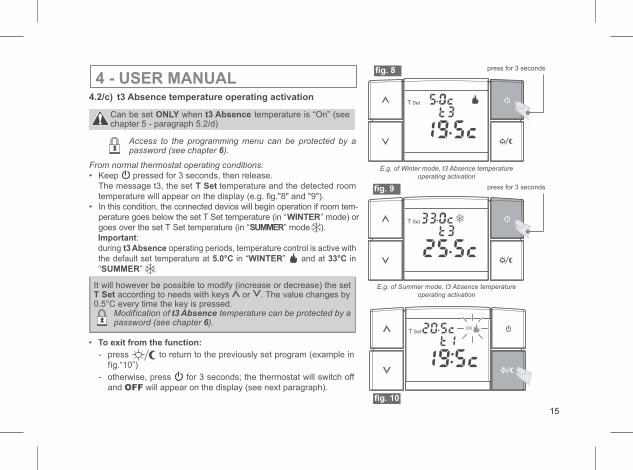
4 - USER MANUAL4.2/c) t3 Absence temperature operating activation
Can be set ONLY when t3 Absence temperature is “On” (seechapter 5 - paragraph 5.2/d)
Access to the programming menu can be protected by apassword (see chapter ).6
From normal thermostat operating conditions:
• Keep pressed for 3 seconds, then release.
The message t3, the set T Set temperature and the detected room
temperature will appear on the display (e.g. fig."8" and "9").
• In this condition, the connected device will begin operation if room tem-
perature goes below the set T Set temperature (in “WINTER” mode) or
goes over the set T Set temperature (in “SUMMER” mode ).
Important:
during t3 Absence operating periods, temperature control is active with
the default set temperature at 5.0°C in “WINTER” and at 33°C in
“ ”SUMMER .
• To exit from the function:
It will however be possible to modify (increase or decrease) the setT Set according to needs with keys or . The value changes by0.5°C every time the key is pressed.
Modification of t3 Absence temperature can be protected by apassword (see chapter ).6
- press to return to the previously set program (example in
fig.“10”)
- otherwise, press for 3 seconds; the thermostat will switch off
and will appear on the display (see next paragraph).OFF
E.g. of Winter mode, t3 Absence temperature
operating activation
E.g. of Summer mode, t3 Absence temperature
operating activation
press for 3 seconds
press for 3 seconds
15
fig. 9
fig. 8
fig. 10
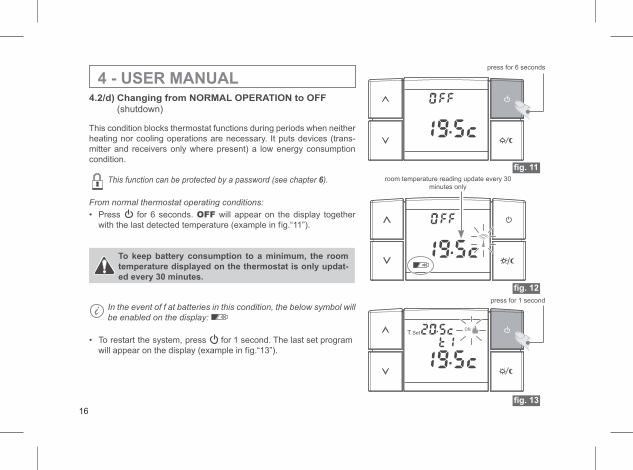
4 - USER MANUALpress for 6 seconds
press for 1 second
room temperature reading update every 30
minutes only
4.2/d) Changing from NORMAL OPERATION to OFF
(shutdown)
This condition blocks thermostat functions during periods when neither
heating nor cooling operations are necessary. It puts devices (trans-
mitter and receivers only where present) a low energy consumption
condition.
This function can be protected by a password (see chapter ).6
From normal thermostat operating conditions:
• Press for 6 seconds. OFF will appear on the display together
with the last detected temperature (example in fig.“11”).
To keep battery consumption to a minimum, the room
temperature displayed on the thermostat is only updat-
ed every 30 minutes.
In the event of f at batteries in this condition, the below symbol will
be enabled on the display:
• To restart the system, press for 1 second. The last set program
will appear on the display (example in fig.“13”).
16
fig. 11
fig. 12
fig. 13
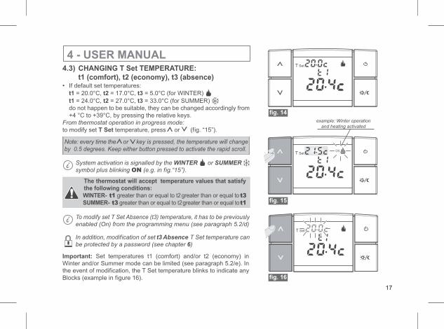
4 - USER MANUAL4.3) CHANGING T Set TEMPERATURE:
t1 (comfort), t2 (economy), t3 (absence)• If default set temperatures:
t1 t2 t3= 20.0°C, = 17.0°C, = 5.0°C (for WINTER)
t1 t2 t3= 24.0°C, = 27.0°C, = 33.0°C (for SUMMER)
do not happen to be suitable, they can be changed accordingly from
+4 °C to +39°C, by pressing the relative keys.
From thermostat operation in progress mode:
to modify set temperature, pressT Set or (fig. “15”).
Note: every time the or key is pressed, the temperature will change
by 0.5 degrees. Keep either button pressed to activate the rapid scroll.
System activation is signalled by the WINTER or SUMMER
symbol plus blinking (e.g. in fON ig.“15”).
The thermostat will accept temperature values that satisfy
the following conditions:
WINTER- t1 greater than or equal to t2greater than or equal to t3
SUMMER- t3 greater than or equal to t2greater than or equal tot1
To modify set T Set Absence (t3) temperature, it has to be previously
enabled (On) from the programming menu (see paragraph 5.2/d)
In addition, modification of set t3 Absence T Set temperature can
be protected by a password (see chapter )6
Important: Set temperatures t1 (comfort) and/or t2 (economy) in
Winter and/or Summer mode can be limited (see paragraph 5.2/e). In
the event of modification, the T Set temperature blinks to indicate any
Blocks (example in figure 16).
example: Winter operation
and heating activated
17
fig. 14
fig. 15
fig. 16
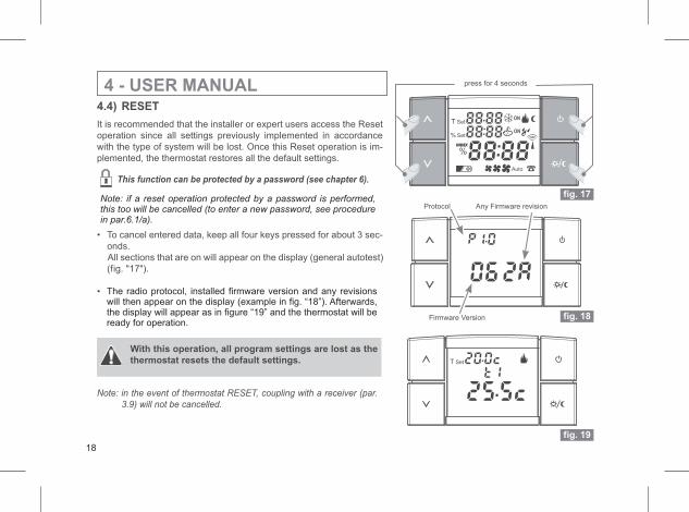
4 - USER MANUAL4.4) RESET
It is recommended that the installer or expert users access the Reset
operation since all settings previously implemented in accordance
with the type of system will be lost. Once this Reset operation is im-
plemented, the thermostat restores all the default settings.
This function can be protected by a password (see chapter 6).
• To cancel entered data, keep all four keys pressed for about 3 sec-
onds.
All sections that are on will appear on the display (general autotest)
(fig. "17").
•
With this operation, all program settings are lost as the
thermostat resets the default settings.
Note: in the event of thermostat RESET, coupling with a receiver (par.
3.9) will not be cancelled.
fig. 17
press for 4 seconds
Firmware Version
Protocol Any Firmware revision
fig. 18
fig. 19
18
The radio protocol, installed firmware version and any revisionswill then appear on the display (example in fig. “18”). Afterwards,the display will appear as in figure “19” and the thermostat will beready for operation.
Note: if a reset operation protected by a password is performed,this too will be cancelled (to enter a new password, see procedurein par.6.1/a).
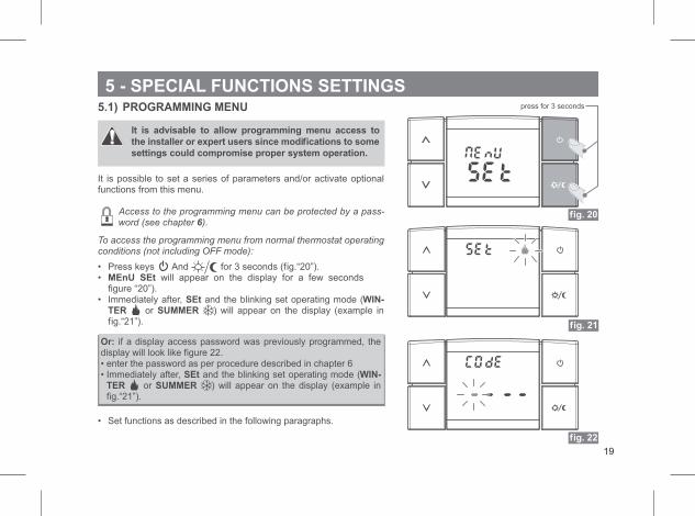
5 - SPECIAL FUNCTIONS SETTINGS5.1) PROGRAMMING MENU
It is advisable to allow programming menu access to
the installer or expert users since modifications to some
settings could compromise proper system operation.
It is possible to set a series of parameters and/or activate optionalfunctions from this menu.
Access to the programming menu can be protected by a pass-word (see chapter ).6
To access the programming menu from normal thermostat operatingconditions (not including OFF mode):
• Press keys And for 3 seconds (fig.“20”).• will appear on the display for a few secondsMEnU SEt
figure “20”).• Immediately after, and the blinking set operating mode (SEt WIN-
TER or SUMMER ) will appear on the display (example infig.“21”).
Or: if a display access password was previously programmed, thedisplay will look like figure 22.• enter the password as per procedure described in chapter 6• Immediately after, and the blinking set operating mode (SEt WIN-
TER or SUMMER ) will appear on the display (example infig.“21”).
• Set functions as described in the following paragraphs.
press for 3 seconds
fig. 20
fig. 21
fig. 22
19
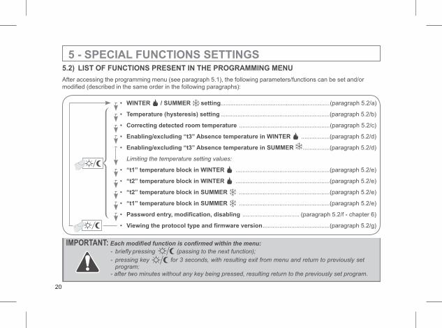
5 - SPECIAL FUNCTIONS SETTINGS5.2) LIST OF FUNCTIONS PRESENT IN THE PROGRAMMING MENU
After accessing the programming menu (see paragraph 5.1), the following parameters/functions can be set and/or
modified (described in the same order in the following paragraphs):
• WINTER / SUMMER .................................................................(paragraph 5.2/a)setting
• Temperature (hysteresis) setting .................................................................(paragraph 5.2/b)
• Correcting detected room temperature ......................................................(paragraph 5.2/c)
• Enabling/excluding “t3” Absence temperature in WINTER .................(paragraph 5.2/d)
• Enabling/excluding “t3” Absence temperature in SUMMER ................(paragraph 5.2/d)
Limiting the temperature setting values:
• “t1” temperature block in WINTER ........................................................(paragraph 5.2/e)
• “t2” temperature block in WINTER ........................................................(paragraph 5.2/e)
• “t2” temperature block in SUMMER ......................................................(paragraph 5.2/e)
• “t1” temperature block in SUMMER ......................................................(paragraph 5.2/e)
• Password entry, modification, disabling .................................. (paragraph 5.2/f - chapter 6)
• Viewing the protocol type and firmware version........................................(paragraph 5.2/g)
IMPORTANT: Each modified function is confirmed within the menu:
- briefly pressing (passing to the next function);
- pressing key for 3 seconds, with resulting exit from menu and return to previously setprogram;
- after two minutes without any key being pressed, resulting return to the previously set program.
20
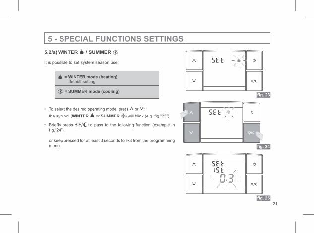
5.2/a) WINTER / SUMMER
It is possible to set system season use:
• To select the desired operating mode, press or :
the symbol (WINTER or SUMMER ) will blink (e.g. fig.“23”).
• Briefly press t o pass to the following function (example in
fIg.“24”).
or keep pressed for at least 3 seconds to exit from the programming
menu.
5 - SPECIAL FUNCTIONS SETTINGS
fig. 23
fig. 24
fig. 25
= WINTER mode (heating)default setting
= SUMMER mode (cooling)
21
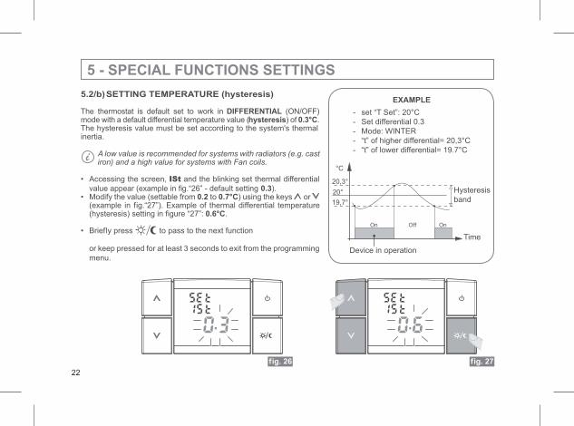
5.2/b)SETTING TEMPERATURE (hysteresis)
The thermostat is default set to work in DIFFERENTIAL (ON/OFF)mode with a default differential temperature value (hysteresis) of 0.3°C.The hysteresis value must be set according to the system's thermalinertia.
A low value is recommended for systems with radiators (e.g. castiron) and a high value for systems with Fan coils.
• Accessing the screen, ISt and the blinking set thermal differential
value appear (example in fig.“26” - default setting ).0.3• Modify the value (settable from 0.2 to 0.7°C) using the keys or
(example in fig.“27”). Example of thermal differential temperature(hysteresis) setting in figure “27”: 0.6°C.
• Briefly press to pass to the next function
or keep pressed for at least 3 seconds to exit from the programming
menu.
5 - SPECIAL FUNCTIONS SETTINGS
fig. 27
- set “T Set”: 20°C
- Set differential 0.3
- Mode: WINTER
- “t” of higher differential= 20,3°C
- “t” of lower differential= 19.7°C
fig. 26
EXAMPLE
°C
Off OnOn
20°
20,3°
19,7°
Hysteresis
band
Time
Device in operation
22
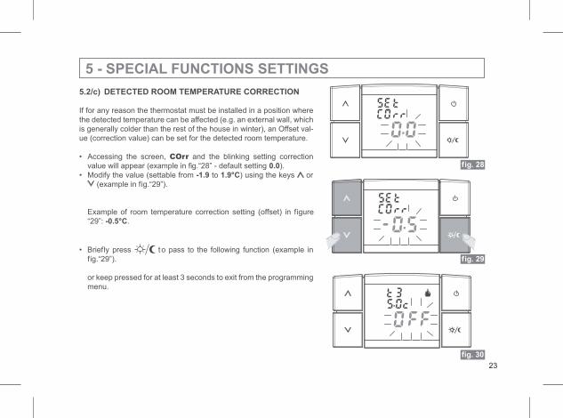
5.2/c) DETECTED ROOM TEMPERATURE CORRECTION
If for any reason the thermostat must be installed in a position where
the detected temperature can be affected (e.g. an external wall, which
is generally colder than the rest of the house in winter), an Offset val-
ue (correction value) can be set for the detected room temperature.
• Accessing the screen, COrr and the blinking setting correction
value will appear (example in fig.“28” - default setting ).0.0
• Modify the value (settable from -1.9 to 1.9°C) using the keys or
(example in fig.“29”).
Example of room temperature correction setting (offset) in figure
“29”: .-0.5°C
• Briefly press to pass to the following function (example in
fig.“29”).
or keep pressed for at least 3 seconds to exit from the programming
menu.
5 - SPECIAL FUNCTIONS SETTINGS
fig. 28
fig. 29
fig. 30
23
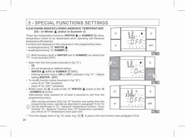
5.2/d) ENABLING/EXCLUDING ABSENCE TEMPERATURE
(t3) - in Winter and/or in Summer
These two independent functions (WINTER or SUMMER ) allowtemperature control to be deactivated when operating with Absencetemperature selected.t3Functions are displayed in this sequence in the programming menu:
• enabling/excluding “t3” WINTER• enabling/excluding “t3” SUMMER .
Both functions (both in WINTER and in SUMMER) are default setto be excluded (OFF).
• Seen from the first screen (example in fig.“31”):- t3,- the set temperature (default setting:
WINTER 5.0°C or SUMMER 33°C),- blinking function status (ON or OFF) (example in fig.“31” - default
setting ).WINTER - OFF• To modify function status (example in fig.“32”):
- press for “ON” (enabled)- press for “OFF” (disabled).
• Briefly press to pass to the “t3” WINTER screen to the “t3- SUMMER screen.Alternatively, keep pressed for at least 3 seconds to exit from theprogramming menu.
After having activated (ON) the "t3" function and exiting from theprogramming menu, operate as described in paragraph "4.2/c" toset the thermostat in "t3 - Absence" temperature function. If youexclude "t3 - Absence" function from "t3" temperature operation,you will be at "t1" temperature level upon exit.
5 - SPECIAL FUNCTIONS SETTINGS
fig. 31
fig. 32
fig. 33
• From the display show in fig. 33, press key to pass to the next function (see paragraph 5.2/e)
24
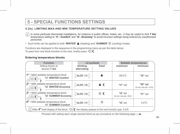
5.2/e) LIMITING MAX AND MIN TEMPERATURE SETTING VALUES
• Such limits can be applied to both “ ”WINTER (heating) and “ ”SUMMER (cooling) modes.
Functions are displayed in this sequence in the programming menu as per the table below:
To pass from one block function to the next, briefly press .
Entering temperature blocks
5 - SPECIAL FUNCTIONS SETTINGS
Function Lit symbols Settable temperatures
blinking fixed maximum minimum
alternating
• MAX settable temperature block 39.0°C “t2” set“ ”t1 WINTER Comfort
• MIN settable temperature block “t1” set“ ”t2 WINTER Economy
• MAX settable temperature block “t3” set“ ”t2 SUMMER Economy
• MIN settable temperature block “t2” set“ ”t1 SUMMER Comfort
After 4° brief display of the block, the display passes to the next function (par. 5.2/f)
bLOC / t1
bLOC / t2
bLOC / t2
bLOC / t1
(to set, see par. 4.2/c)
Setting blocks at
desired T Set
(to set, see par. 42/c)
1°
2°
3°
4°
Proceed with setting each single desired block as per procedure on the following page
25
In some particular thermostat installations, for instance in public offices, hotels, etc., it may be useful to limitsetting to “ ” and “ ” to avoid incorrect settings being entered by unauthorised
personnel.
T Sett1 - Comfort t2 - Economytemperature
“t3” set
“t1” set
4.0°C
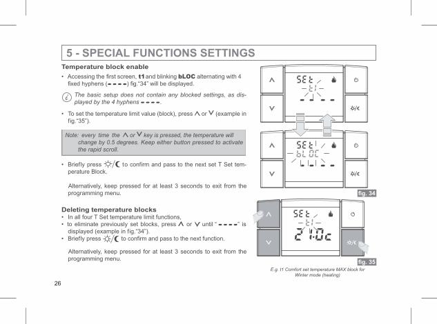
fig. 34
fig. 35
Temperature block enable
• Accessing the first screen, t1and blinking bLOC alternating with 4
fixed hyphens ( ) fig.“34” will be displayed.
The basic setup does not contain any blocked settings, as dis-
played by the 4 hyphens .
• To set the temperature limit value (block), press or (example in
fig.“35”).
Note: every time the or key is pressed, the temperature will
change by 0.5 degrees. Keep either button pressed to activate
the rapid scroll.
• Briefly press to confirm and pass to the next set T Set tem-
perature Block.
Alternatively, keep pressed for at least 3 seconds to exit from the
programming menu.
Deleting temperature blocks• In all four T Set temperature limit functions,
• to eliminate previously set blocks, press or until “ ” is
displayed (example in fig.“34”).
• Briefly press to confirm and pass to the next function.
Alternatively, keep pressed for at least 3 seconds to exit from the
programming menu.
5 - SPECIAL FUNCTIONS SETTINGS
E.g. t1 Comfort set temperature MAX block for
Winter mode (heating)
26
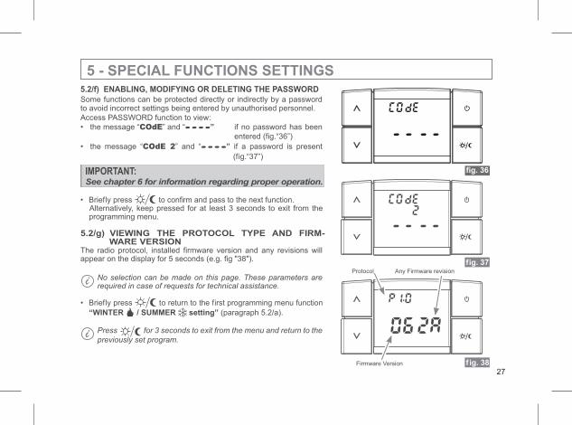
5.2/f) ENABLING, MODIFYING OR DELETING THE PASSWORD
5 - SPECIAL FUNCTIONS SETTINGS
Some functions can be protected directly or indirectly by a passwordto avoid incorrect settings being entered by unauthorised personnel.
Access PASSWORD function to view:
• the message “COdE” and “ ” if no password has been
entered (fig.“36”)
• the message “COdE 2” and “ ” if a password is present
(fig.“37”)
IMPORTANT:See chapter 6 for information regarding proper operation.
• Briefly press to confirm and pass to the next function.Alternatively, keep pressed for at least 3 seconds to exit from theprogramming menu.
5.2/g) VIEWING THE PROTOCOL TYPE AND FIRM-WARE VERSION
The radio protocol, installed firmware version and any revisions willappear on the display for 5 seconds (e.g. fig "38").
No selection can be made on this page. These parameters arerequired in case of requests for technical assistance.
• Briefly press to return to the first programming menu function
“WINTER / SUMMER setting” (paragraph 5.2/a).
Press for 3 seconds to exit from the menu and return to the
previously set program.
f ig. 38
fig. 37
Firmware Version
Protocol Any Firmware revision
27
fig. 36
6 - PASSWORD
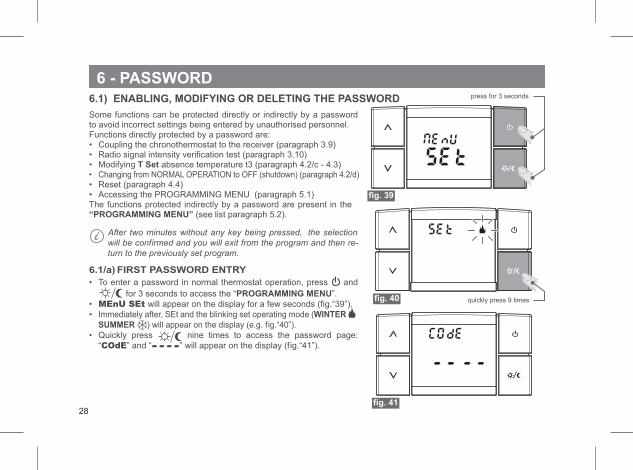
6.1) ENABLING, MODIFYING OR DELETING THE PASSWORD
Some functions can be protected directly or indirectly by a passwordto avoid incorrect settings being entered by unauthorised personnel.Functions directly protected by a password are:• Coupling the chronothermostat to the receiver (paragraph 3.9)• Radio signal intensity verification test (paragraph 3.10)• Modifying T Set absence temperature t3 (paragraph 4.2/c - 4.3)• Changing from NORMAL OPERATION to OFF (shutdown) (paragraph 4.2/d)• Reset (paragraph 4.4)• Accessing the PROGRAMMING MENU (paragraph 5.1)The functions protected indirectly by a password are present in the“PROGRAMMING MENU” (see list paragraph 5.2).
After two minutes without any key being pressed, the selection
will be confirmed and you will exit from the program and then re-
turn to the previously set program.
6.1/a) FIRST PASSWORD ENTRY
• To enter a password in normal thermostat operation, press and
for 3 seconds to access the “ ”.PROGRAMMING MENU
• MEnU SEt will appear on the display for a few seconds (fig.“39”).
• Immediately after, SEt and the blinking set operating mode (WINTER
SUMMER ) will appear on the display (e.g. fig.“40”).
• Quickly press nine times to access the password page:
“COdE” and “ ” will appear on the display (fig.“41”).
press for 3 seconds
quickly press 9 times
28
fig. 39
fig. 40
fig. 41
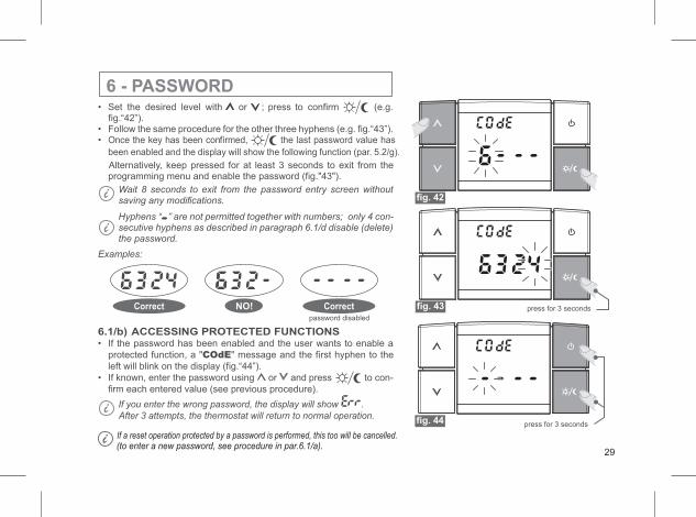
6 - PASSWORD• Set the desired level with or ; press to confirm (e.g.
fig.“42”).• Follow the same procedure for the other three hyphens (e.g. fig.“43”).• Once the key has been confirmed, the last password value has
been enabled and the display will show the following function (par. 5.2/g).
Alternatively, keep pressed for at least 3 seconds to exit from theprogramming menu and enable the password (fig."43").
Wait 8 seconds to exit from the password entry screen withoutsaving any modifications.
Hyphens “ ” are not permitted together with numbers; only 4 con-secutive hyphens as described in paragraph 6.1/d disable (delete)the password.
Examples:
press for 3 seconds
6.1/b) ACCESSING PROTECTED FUNCTIONS• If the password has been enabled and the user wants to enable a
protected function, a "COdE" message and the first hyphen to the
left will blink on the display (fig.“44”).
• If known, enter the password using or and press to con-
firm each entered value (see previous procedure).
If you enter the wrong password, the display will show .
After 3 attempts, the thermostat will return to normal operation.
press for 3 seconds“examples”Correct NO!password disabled
Correct
29
fig. 42
fig. 43
fig. 44
If a reset operation protected by a password is performed, this too will be cancelled.(to enter a new password, see procedure in par.6.1/a).
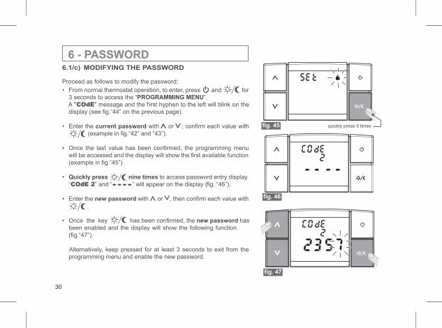
6 - PASSWORD6.1/c) MODIFYING THE PASSWORD
Proceed as follows to modify the password:
• From normal thermostat operation, to enter, press and for
3 seconds to access the “ ”.PROGRAMMING MENU
A "COdE" message and the first hyphen to the left will blink on the
display (see fig.“44” on the previous page).
• Enter the current password with or ; confirm each value with
(example in fig.“42” and “43”).
• Once the last value has been confirmed, the programming menu
will be accessed and the display will show the first available function
(example in fig.“45”)
• Quickly press nine times to access password entry display.
“ ” and “COdE 2 ” will appear on the display (fig. “46”).
• Enter the new password with or , then confirm each value with
.
• Once the key has been confirmed, the hasnew password
been enabled and the display will show the following function
(fig.“47”).
Alternatively, keep pressed for at least 3 seconds to exit from the
programming menu and enable the new password.
quickly press 9 times
30
fig. 46
fig. 47
fig. 45
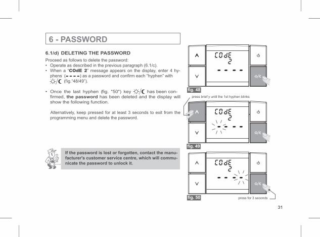
6.1/d) DELETING THE PASSWORD
Proceed as follows to delete the password:
• Operate as described in the previous paragraph (6.1/c).
• When a “COdE 2” message appears on the display, enter 4 hy-
phens ( ) as a password and confirm each “hyphen” with
(fig.“48/49”).
• Once the last hyphen (fig. "50") key has been con-
firmed, the password has been deleted and the display will
show the following function.
Alternatively, keep pressed for at least 3 seconds to exit from the
programming menu and delete the password.
If the password is lost or forgotten, contact the manu-
facturer's customer service centre, which will commu-
nicate the password to unlock it.
press for 3 seconds
press brief y until the 1st hyphen blinks
6 - PASSWORD
31
fig. 49
fig. 50
fig. 48
Declaration of conformity: We hereby declare that the product below meets the essential requirements required by Directive
R&TTE1999/5/CE. Product compliance to this Directive is confirmed by the CE marking on the product and in this document.
A full copy of the "Declaration of Conformity" of Directive R&TTE1999/5/CEE is available upon request at the address of the
Registrant, below.
Registrant:
Model:
Marking: