Embed Size (px)
Citation preview
Erez Ribak1,3 and Szymon Gladysz2,3
1 Physics, Technion, Haifa, Israel2 European Southern Observatory3 Research performed at NUI, Galway
Thanks to Ruth Mackay for helping with the lab experiment and to Chris Dainty for his full support
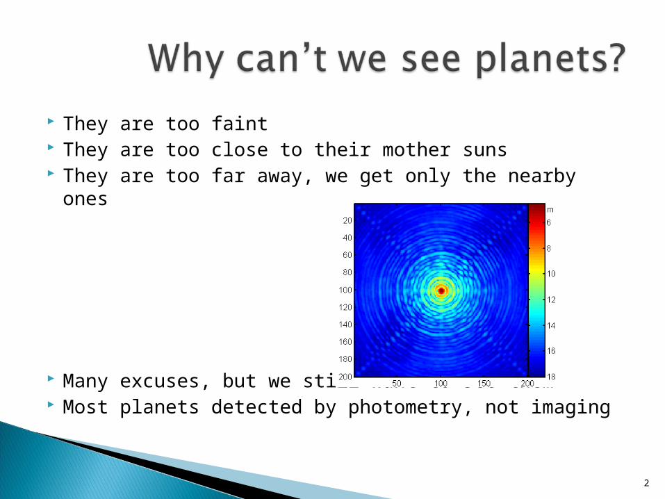
They are too faint They are too close to their mother suns They are too far away, we get only the nearby ones
Many excuses, but we still want to see them Most planets detected by photometry, not imaging
2
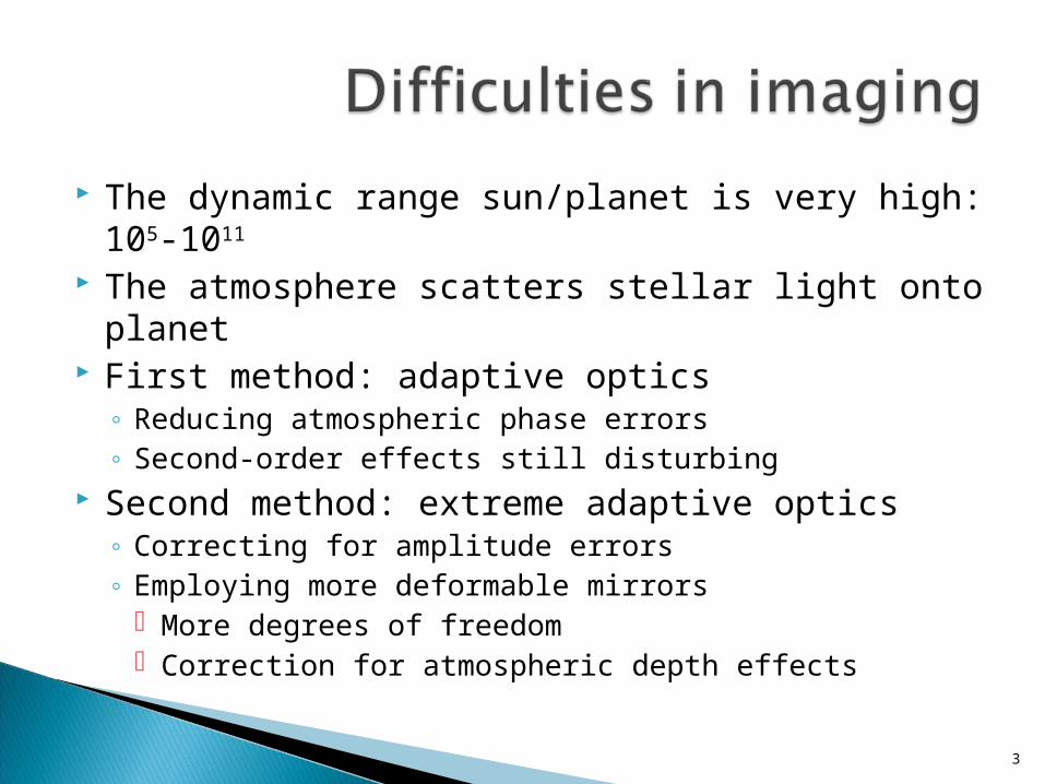
The dynamic range sun/planet is very high: 105-1011
The atmosphere scatters stellar light onto planet First method: adaptive optics
◦ Reducing atmospheric phase errors◦ Second-order effects still disturbing
Second method: extreme adaptive optics◦ Correcting for amplitude errors◦ Employing more deformable mirrors
More degrees of freedom Correction for atmospheric depth effects
3
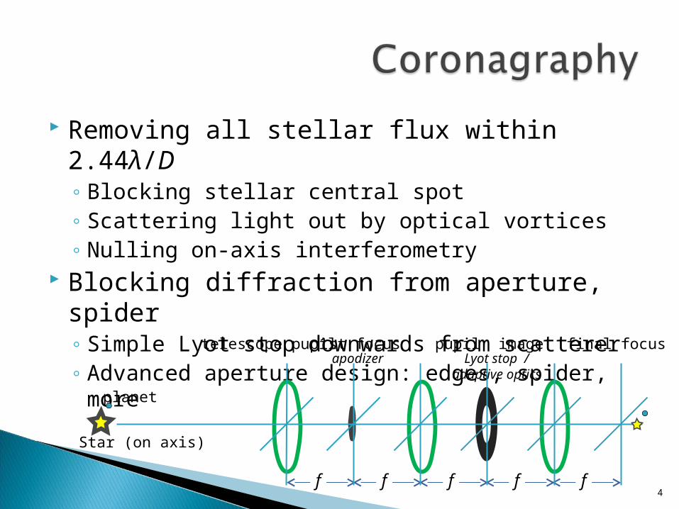
Removing all stellar flux within 2.44λ/D◦ Blocking stellar central spot◦ Scattering light out by optical vortices◦ Nulling on-axis interferometry
Blocking diffraction from aperture, spider◦ Simple Lyot stop downwards from scatterer◦ Advanced aperture design: edges, spider, more
4f f f f f
planet
Star (on axis)
telescope pupil 1st focus pupil image final focusapodizer Lyot stop /
adaptive optics
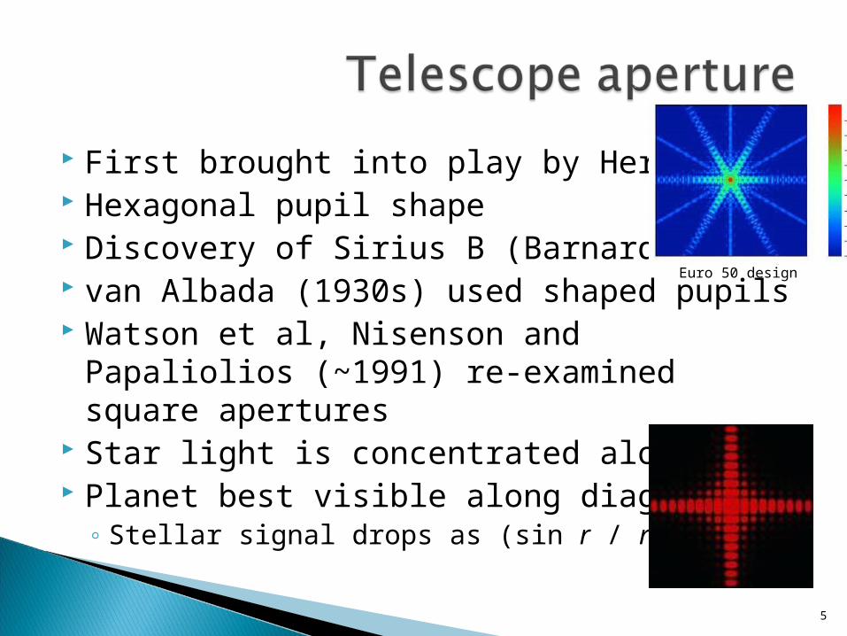
First brought into play by Herschel Hexagonal pupil shape Discovery of Sirius B (Barnard, 1909) van Albada (1930s) used shaped pupils Watson et al, Nisenson and Papaliolios
(~1991) re-examined square apertures Star light is concentrated along axes Planet best visible along diagonals
◦ Stellar signal drops as (sin r / r)4
5
Euro 50 design
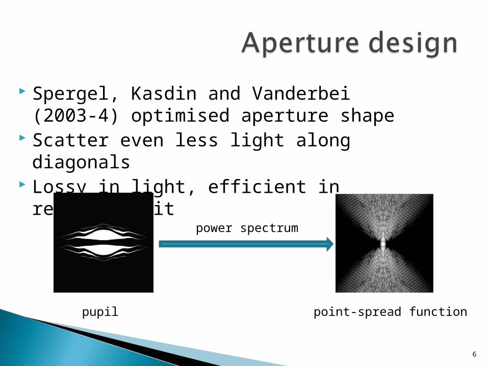
Spergel, Kasdin and Vanderbei (2003-4) optimised aperture shape
Scatter even less light along diagonals Lossy in light, efficient in reordering it
6
power spectrum
pupil point-spread function
Ground and space observations suffer from wave front phase errors
Relatively easy to fix by adaptive optics◦ Strong, nearby reference signal
Extreme adaptive optics correct amplitude errors and second order phase errors
Even combining coronagraphy and adaptive optics still leaves residual but detrimental stellar light leakage
7
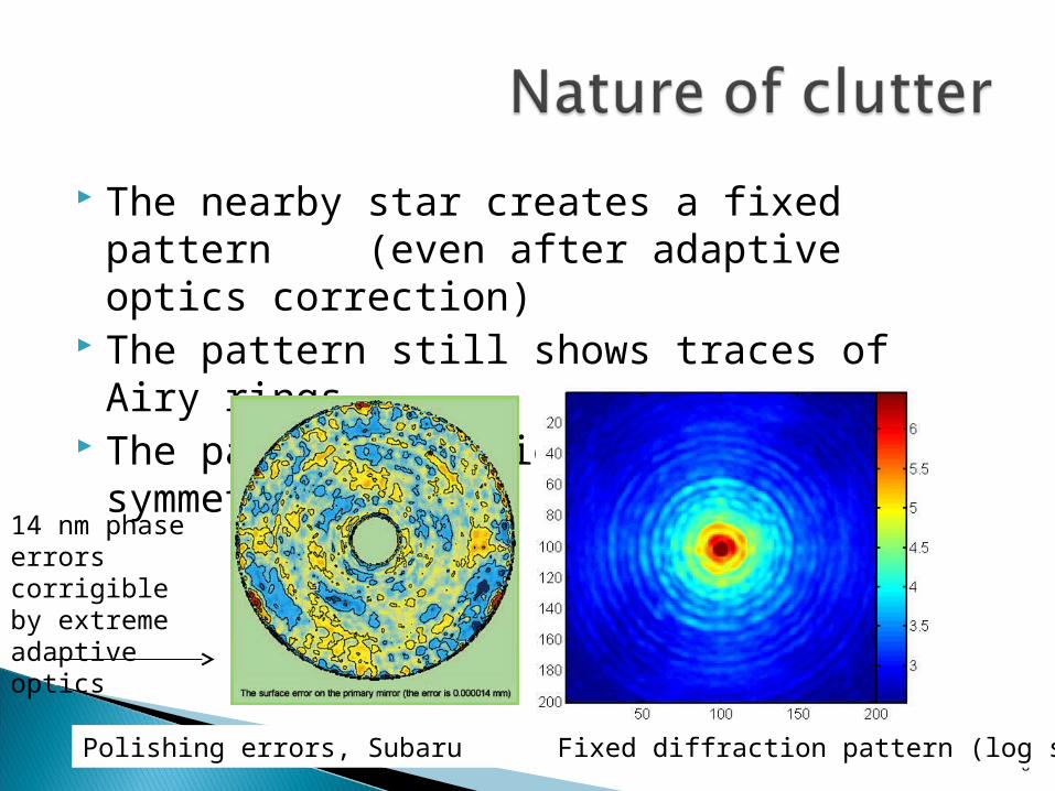
The nearby star creates a fixed pattern (even after adaptive optics correction)
The pattern still shows traces of Airy rings The pattern has high rotational symmetry
8Polishing errors, Subaru Fixed diffraction pattern (log scale)
14 nm phase errors corrigible by extreme adaptive optics

If the symmetry is created by the aperture shape, modify this shape
If the modification is insufficient, modify the modification◦ Turn the modified pupil around◦ If turning is not enough, remodify pupil shape
We chose a mechanically simple solution◦ Block the side of the telescope pupil (or its copy)◦ Rotate the occluding mask
9
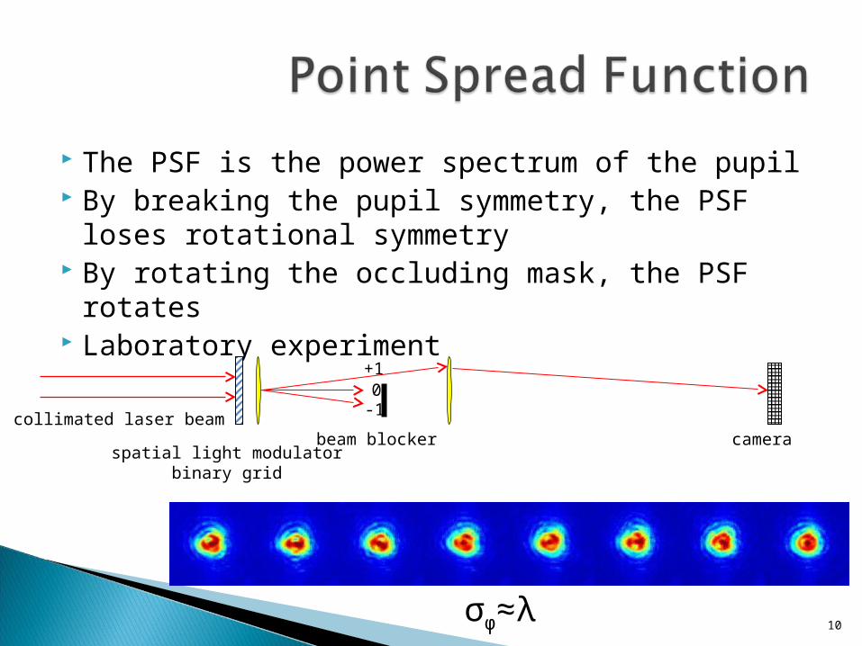
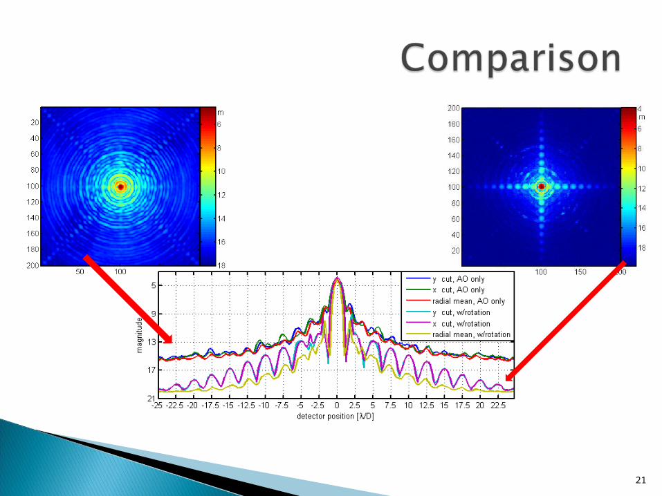
The PSF is the power spectrum of the pupil By breaking the pupil symmetry, the PSF loses
rotational symmetry By rotating the occluding mask, the PSF rotates Laboratory experiment
10
collimated laser beam
spatial light modulatorbinary grid
beam blocker
+1
-10
camera
σφ≈λ
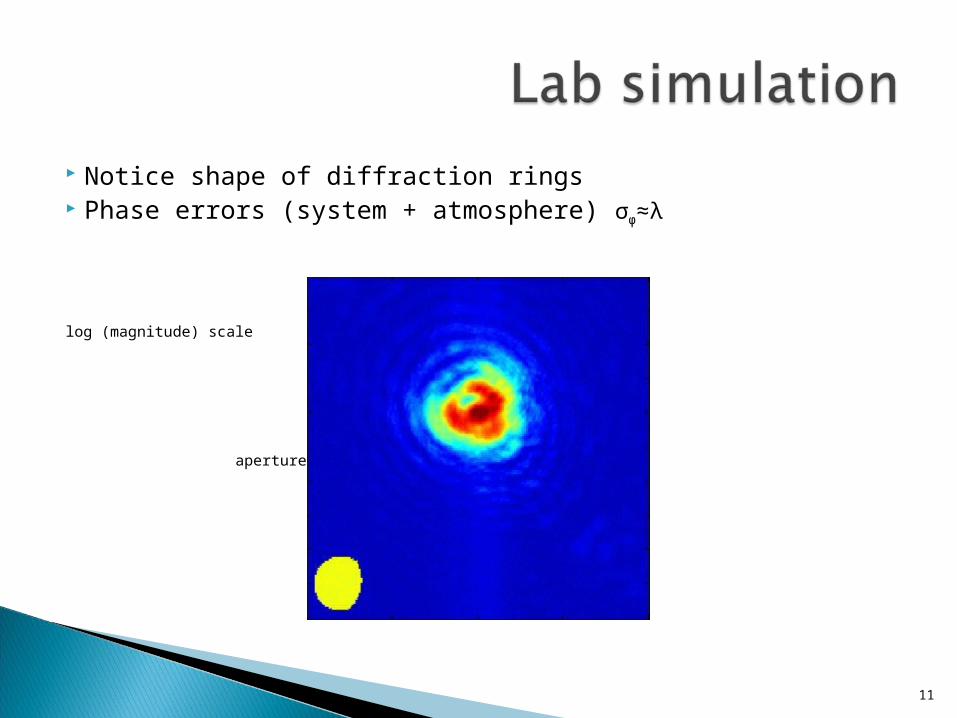
Notice shape of diffraction rings Phase errors (system + atmosphere) σφ≈λ
log (magnitude) scale
aperture
11

As the pupil rotates, Airy rings shrink/expand
The zero intensity rings sweeps in/out As a zero ring passes by planet, it will become
visible12
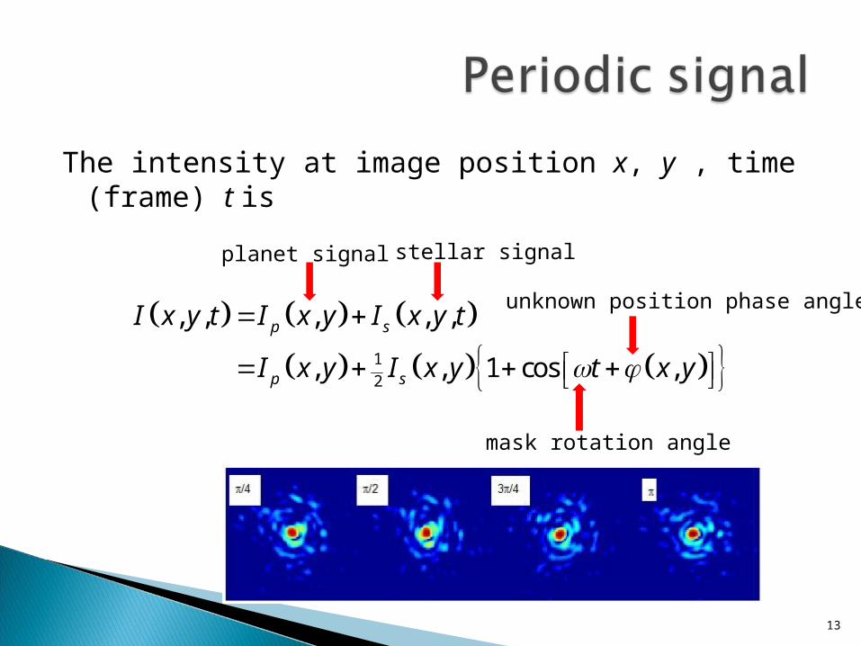
The intensity at image position x, y , time (frame) t is
13
1
2
, , , , ,
, , 1 cos ,
p s
p s
I x y t I x y I x y t
I x y I x y t x y
planet signal stellar signal
unknown position phase angle
mask rotation angle
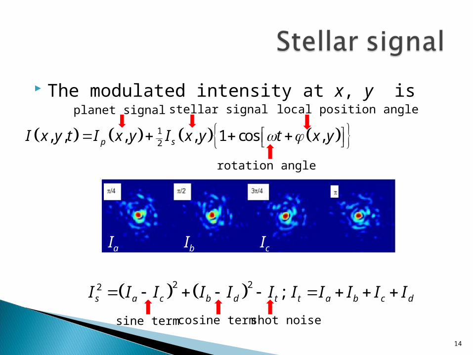
The modulated intensity at x, y is
14
1
2, , , , 1 cos ,p sI x y t I x y I x y t x y
planet signal stellar signal local position angle
rotation angle
Ia Ib Ic Id
2 22 ; s a c b d t t a b c dI I I I I I I I I I I
sine term cosine term shot noise
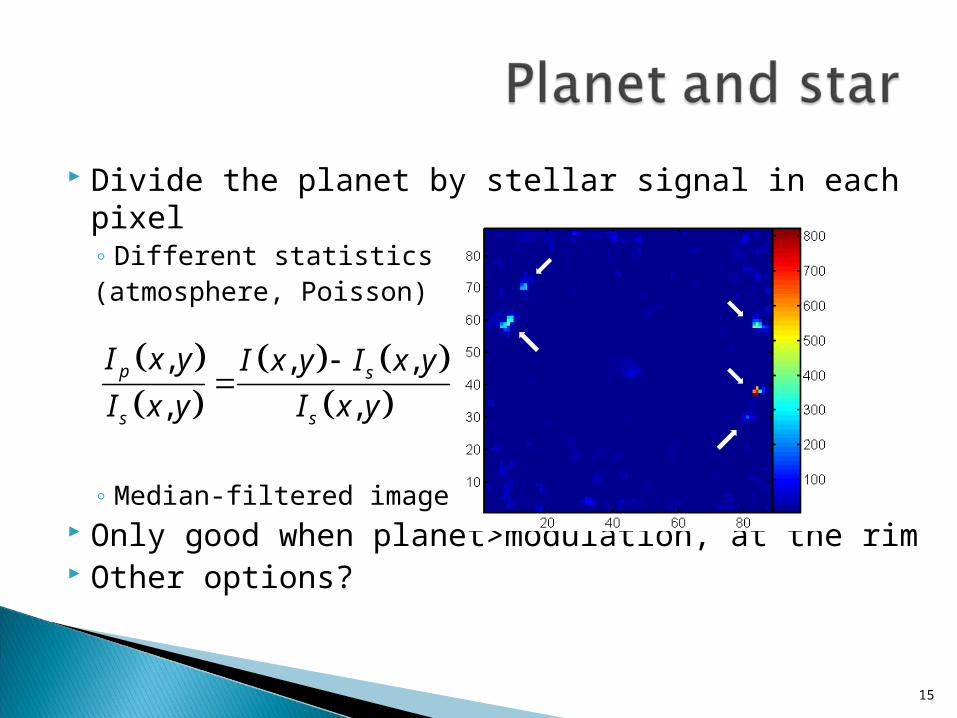
Divide the planet by stellar signal in each pixel◦ Different statistics(atmosphere, Poisson)
◦ Median-filtered image Only good when planet>modulation, at the rim Other options?
15
, , ,
, ,p s
s s
I x y I x y I x y
I x y I x y
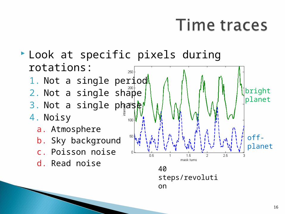
Look at specific pixels during rotations:1. Not a single period2. Not a single shape3. Not a single phase4. Noisy
a. Atmosphereb. Sky backgroundc. Poisson noised. Read noise
16
off-planet
bright planet
40 steps/revolution

sky
planet
suggested methods◦ Fit typical period, subtract
Time domain Frequency domain
◦ Search for different statistics Rely on atmosphere vs. Poisson vs. Gaussian
◦ Wait until minima occur, at whatever angle Only sky background and planet will show Similar to dark speckle (but with active nudge)
17
1
2, , , , 1 , , , ,p s skyI x y t I x y I x y P t x y I x y n x y t
Modelled SPHERE, the planet finder for the VLT, with the PAOLA AO package Created AO-corrected wave fronts Added static aberrations from a mirror error map, σ = 20 nm Added a realization of an f -2 spectrum from additional optical components, σ = 10 nm The coronagraphic module was not included λ =1600±15 nm (methane band), but Spectral Differential Imaging was not employed The global tip and tilt were left in Generated 200 short (dt = 0.1 s or 0.5 s) exposures Between exposures the eccentric aperture was rotated by 9°, total 5 cycles per data-
cube Asterism of a primary star and 36 planets, all with same PSF The star was magnitude 4, the planets dropping from 12 to 20 outwards Added Poisson, background (14 mag arcsec-2) and readout noise (10 e-) The focal-plane sampling was 0.25λ/D (D = 8.2 m) The planets were placed in a central cross, spaced by 10 pixels, or 2.5λ/D , or 0.1'‘ Planets locations nearly coincide with the Airy rings
18
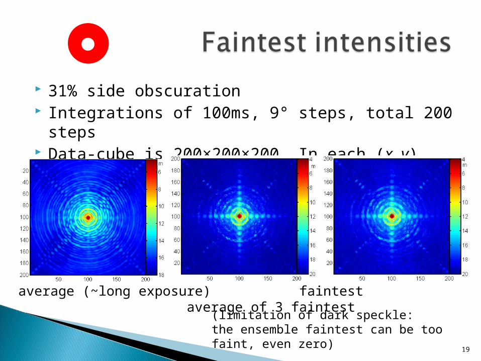
31% side obscuration Integrations of 100ms, 9° steps, total 200 steps Data-cube is 200×200×200. In each (x, y) pixel:
19
average (~long exposure) faintest average of 3 faintest
(limitation of dark speckle:the ensemble faintest can be too faint, even zero)

This 31% side obscuration did not uncover all pixels Repeat with other values: 11%, 16%, 21%, 26%, 31% Now data-cube has 200×200×1000 values For weakest occurrence: keep only 200×200 minima
20
average (~long exposure) faintest (31%) faintest (11%-31%)
21

22
f f f f f
planet
Star (on axis)
telescope pupil 1st focus pupil image final focusapodizer Lyot stop /
adaptive optics
• Changing the occulting aperture size and rotating it at the same time• The blocked portion grows from 0 up to 24% of the diameter• The cycle repeats at 7/3 times the rotation speed• Employ planetary gear: non-circular or axis-displacing
23
• A simple rotating mask removes symmetries of the pupil• Main limitation is short exposure• Data analysis:
• Averaging over cycles (yet) unsuccessful• Finding data-cube minima is prone to statistics of extrema
• Higher contrast achievable with star apodiser (not included)• Next:
• Combine Airy ring wobble by aperture and by λ (Thatte)• Laboratory white-light experiments• Observatory tests with AO system