Embed Size (px)
Citation preview

ERM-MUX/Plus E1 Multi-Service Access Multiplexer


LEGAL
The information in this publication has been carefully checked and is believed to be entirely accurate at the time of publication.
CTC Union Technologies assumes no responsibility, however, for possible errors or omissions, or for any consequences
resulting from the use of the information contained herein. CTC Union Technologies reserves the right to make changes in its
products or product specifications with the intent to improve function or design at any time and without notice and is not
required to update this documentation to reflect such changes.
CTC Union Technologies makes no warranty, representation, or guarantee regarding the suitability of its products for any
particular purpose, nor does CTC Union assume any liability arising out of the application or use of any product and
specifically disclaims any and all liability, including without limitation any consequential or incidental damages.
CTC Union products are not designed, intended, or authorized for use in systems or applications intended to support or sustain
life, or for any other application in which the failure of the product could create a situation where personal injury or death may
occur. Should the Buyer purchase or use a CTC Union product for any such unintended or unauthorized application, the Buyer
shall indemnify and hold CTC Union Technologies and its officers, employees, subsidiaries, affiliates, and distributors
harmless against all claims, costs, damages, expenses, and reasonable attorney fees arising out of, either directly or indirectly,
any claim of personal injury or death that may be associated with such unintended or unauthorized use, even if such claim
alleges that CTC Union Technologies was negligent regarding the design or manufacture of said product.
TRADEMARKS
Microsoft is a registered trademark of Microsoft Corp.
HyperTerminal™ is a registered trademark of Hilgraeve Inc.
WARNING:
This equipment has been tested and found to comply with the limits for a Class A digital device, pursuant to Part 15 of the
FCC Rules. These limits are designed to provide reasonable protection against harmful interference when the equipment is
operated in a commercial environment. This equipment generates, uses, and can radiate radio frequency energy and if not
installed and used in accordance with the instruction manual may cause harmful interference in which case the user will be
required to correct the interference at his own expense. NOTICE: (1) The changes or modifications not expressively approved
by the party responsible for compliance could void the user's authority to operate the equipment. (2) Shielded interface cables
and AC power cord, if any, must be used in order to comply with the emission limits.
CISPR PUB.22 Class A COMPLIANCE:
This device complies with EMC directive of the European Community and meets or exceeds the following technical standard.
EN 55022 - Limits and Methods of Measurement of Radio Interference Characteristics of Information Technology Equipment.
This device complies with CISPR Class A.
WARNING:
This is a Class A product. In a domestic environment this product may cause radio interference in which case the user may be
required to take adequate measures.
CE NOTICE
Marking by the symbol CE indicates compliance of this equipment to the EMC directive of the European Community. Such
marking is indicative that this equipment meets or exceeds the following technical standards: EN
55022:1994/A1:1995/A2:1997 Class A and EN61000-3-2:1995, EN61000-3-3:1995 and EN50082-1:1997

CTC Union Technologies Co., Ltd.
Far Eastern Vienna Technology Center (Neihu Technology Park)
8F, No. 60, Zhouzi St.
Neihu, Taipei, 114
Taiwan
Phone: +886-2-2659-1021
FAX: +886-2-2799-1355
ERM-MUX/Plus
E1 Multi-Service Access Multiplexer
User Manual
Version 4.0 December 2008 Release
Version 4.1 June 2009 Update
Version 4.2 March 2011 Update
Version 4.3 April 2014 Update
Version 4.4 June 2014 Update
This manual supports the following models:
ERM-MUX/Plus
This document is the current official release manual. Please check CTC Union's website for any updated manual or contact us
by E-mail at [email protected]. Please address any comments for improving this manual or to point out omissions or errors to
[email protected]. Thank you.
2008-2014 CTC Union Technologies Co., Ltd.
All Rights Reserved
The contents of this document are subject to change without any prior notice.

Table of Contents
CHAPTER 1 INTRODUCTION ................................................................................................................................................ 9
1.1 GENERAL FEATURES ................................................................................................................................................................... 9 1.1.1 Power Supply Modules ................................................................................................................................................ 10 1.1.2 CPU Control Card ......................................................................................................................................................... 10 1.1.3 E1 Line Card ................................................................................................................................................................. 10 1.1.4. N64K/V35 Line Card.................................................................................................................................................... 11 1.1.5 A/SYNC-128K Line Card ............................................................................................................................................... 11 1.1.6 G703-64K Line Card ..................................................................................................................................................... 11 1.1.7 FXS Line Card ............................................................................................................................................................... 11 1.1.8 FXO Line Card .............................................................................................................................................................. 11 1.1.9 E&M Line Card ............................................................................................................................................................. 12 1.1.10 X.50 Line Card ............................................................................................................................................................ 12 1.1.11 ET100 Ethernet Bridge Line Card ............................................................................................................................... 12 1.1.12 RS-485/RS-422 Line Card ........................................................................................................................................... 12 1.1.13 SUB-E1 Line Card (Under) .......................................................................................................................................... 12 1.1.14 Additional Features ................................................................................................................................................... 12
1.2 TECHNICAL SPECIFICATIONS ....................................................................................................................................................... 12 1.2.1 E1 Line Card ................................................................................................................................................................. 12 1.2.2 N64/V35 Line Card ....................................................................................................................................................... 13 1.2.3 RS-232 and A/SYNC-C Line Card .................................................................................................................................. 13 1.2.4 G703-64K Line Card ..................................................................................................................................................... 13 1.2.5 E&M Line Card ............................................................................................................................................................. 13 1.2.6 FXO Line Card .............................................................................................................................................................. 13 1.2.7 FXS Line Card ............................................................................................................................................................... 13 1.2.8 ET100 Ethernet Bridge Line Card ................................................................................................................................. 14 1.2.9 RS-485/RS-422 Serial Tributary Card ........................................................................................................................... 14 1.2.10 X.50 Module Line Card ............................................................................................................................................... 14 1.2.11 SUB-E1 Line Card (Under Development) .................................................................................................................... 14 1.2.12 Power Modules .......................................................................................................................................................... 14 1.2.13 Physical Specifications ............................................................................................................................................... 14
CHAPTER 2 INSTALLATION ................................................................................................................................................ 15
2.1 INSTALLING BRACKETS ON CHASSIS ............................................................................................................................................. 15 2.2 POWER MODULES AND LINE CARD INSTALLATION .......................................................................................................................... 15
2.2.1 Cable connectors ......................................................................................................................................................... 16 2.3 AUXILIARY CONNECTIONS ON REAR OF CHASSIS ............................................................................................................................. 16 2.4 CONNECTING POWER SUPPLIES .................................................................................................................................................. 16 2.5 CONNECTING SNMP NETWORK MANAGEMENT ACCESS ................................................................................................................. 17 2.6 CONNECTING NMP NETWORK MANAGEMENT ACCESS .................................................................................................................. 17 2.7 CONNECTING MONITOR/CONTROL TERMINAL .............................................................................................................................. 18 2.8 CONNECTING G.703 EXTERNAL CLOCK ........................................................................................................................................ 18 2.9 CONNECTING E1 CIRCUITS ........................................................................................................................................................ 18 2.10 CONNECTING I/O CARDS ........................................................................................................................................................ 18 2.11 CONNECTING SYNC TAIL CIRCUITS ............................................................................................................................................. 19
CHAPTER 3 LED INDICATORS AND CABLE PIN DEFINITIONS ............................................................................................... 21
3.1 FRONT PANEL LED INDICATORS .................................................................................................................................................. 21 3.2 INTERFACE CONNECTOR PINS AND DEFINITIONS ............................................................................................................................ 23
3.2.1 8xE1-BNC Cable Pins .................................................................................................................................................... 23 3.2.2 N64K(V.35) CARD ............................................................................................................................................................... 24
3.2.3 A/SYNC 128 Card ......................................................................................................................................................... 27 3.2.4 G703/64K Card ......................................................................................................................................................... 28 3.2.5 E&M Card .............................................................................................................................................................. 28 3.2.6 FXS Card .................................................................................................................................................................... 29 3.2.7 FXO Card ................................................................................................................................................................... 29 3.2.8 RS485/422 Pin Assignment ....................................................................................................................................... 29
CHAPTER 4 HARDWARE SETTINGS .................................................................................................................................... 31
4.1 E1 CARD ................................................................................................................................................................................ 31 4.2 N64K/V35 CARD ................................................................................................................................................................. 31 4.3 E&M CARD ............................................................................................................................................................................ 32
Table of Contents
4.3.1 E&M Type Setting ........................................................................................................................................................ 32 4.3.2 Signaling Type Setting .............................................................................................................................................. 32 4.3.3 E&M Signaling Type Setting ........................................................................................................................................ 32
CHAPTER 5 CONSOLE OPERATION .................................................................................................................................... 33
5.1 INITIAL SETUP ......................................................................................................................................................................... 33 5.1.1 Boot ............................................................................................................................................................................. 33 5.1.2 Input Password ............................................................................................................................................................ 34 5.1.3 Main Menu .................................................................................................................................................................. 34
5.2 SET E1 CARD .......................................................................................................................................................................... 35 5.2.1 Set Frame Mode .......................................................................................................................................................... 35 5.2.2 Set CRC Mode .............................................................................................................................................................. 35 5.2.3 Set Loop Back ............................................................................................................................................................... 36 5.2.4 Set Line Code ............................................................................................................................................................... 36 5.2.5 Set JITTER ..................................................................................................................................................................... 36 5.2.6 Set Timeslot Cross Connect .......................................................................................................................................... 36
5.3 SET I/O CARD ......................................................................................................................................................................... 37 5.3.1 N64K/V35 card configuration ...................................................................................................................................... 37 5.3.2 N64K/V35 menu display .............................................................................................................................................. 38 5.3.3 N64K/V35 channel menu display ................................................................................................................................. 38 5.3.4 Set multiplex E1 number .............................................................................................................................................. 38 5.3.5 Set loop mode .............................................................................................................................................................. 39 5.3.6 Set clock mode ............................................................................................................................................................. 39
5.4 SET RS-232 CARD ................................................................................................................................................................... 39 5.5 SET G703-64K CARD .............................................................................................................................................................. 39
5.5.1 G703-64K menu display ............................................................................................................................................... 40 5.6 SET A/SYNC-128K CARD ........................................................................................................................................................ 40
5.6.1 A/SYNC-RS232 menu display ....................................................................................................................................... 40 5.6.2 A/SYNC-RS232 Channel menu display ......................................................................................................................... 40
5.7 SET FXS CARD ......................................................................................................................................................................... 41 5.7.1 FXS menu display ......................................................................................................................................................... 41 5.7.2 Channel menu display .................................................................................................................................................. 41 5.7.3 Set Work mode ............................................................................................................................................................ 41
5.8 SET FXO CARD ....................................................................................................................................................................... 42 5.9 SET E&M CARD ...................................................................................................................................................................... 42
5.9.1 E&M MENU DISPLAY ................................................................................................................................................... 42 5.9.2 E&M Channel menu display ......................................................................................................................................... 42
5.10 SET X.50 CARD ..................................................................................................................................................................... 43 5.11 SET ET100 CARD .................................................................................................................................................................. 43
5.11.1 Set multiplex E1 number ............................................................................................................................................ 43 5.11.2 Set Auto Negotiation ................................................................................................................................................. 43 5.11.3 Set Full / Half Duplex ................................................................................................................................................. 44 5.11.4 Set UTP Port Speed .................................................................................................................................................... 44 5.11.5 Set Flow Control ......................................................................................................................................................... 44 5.11.6 Set MAC FILTERING .................................................................................................................................................... 44 5.11.7 Set Local Loop ............................................................................................................................................................ 44
5.12 SET RS485/422 CARD .......................................................................................................................................................... 45 5.12.1 RS485 Configuration Menu ........................................................................................................................................ 45 5.12.2 RS485 Channel Configuration Display ....................................................................................................................... 45 5.12.3 Set multiplex E1 number ............................................................................................................................................ 45 5.12.4 Set Loopback .............................................................................................................................................................. 46
5.13 DISPLAY DEVICES CONFIGURATION ............................................................................................................................................ 46 5.14 SAVE CONFIGURATION ............................................................................................................................................................ 47 5.15 RESET DEVICE CONFIGURATION TO DEFAULT .............................................................................................................................. 47 5.16 BROWSE/MODIFY SYSTEM PARAMETERS ................................................................................................................................... 47
5.16.1 Display system version............................................................................................................................................... 48 5.16.2 Modify System Clock .................................................................................................................................................. 48
5.17 MODIFY NMP /SNMP PARAMETER ......................................................................................................................................... 48 5.17.1 Set up timeslot of in-band NMP ............................................................................................................................. 48 5.17.2 Set down timeslot of in-band NMP ......................................................................................................................... 48 5.17.3 Disable NMP .............................................................................................................................................................. 49 5.17.4 Change IP address ..................................................................................................................................................... 49 5.17.5 Device Address (NMP) ............................................................................................................................................... 50
Table of Contents
5.17.6 SET DOWNDEVICE ADDRESS ................................................................................................................................... 50 5.18 SET BACKUP E1 .................................................................................................................................................................. 50 5.19 SET PASSWORD ..................................................................................................................................................................... 50 5.20 SETUP TIME ....................................................................................................................................................................... 50 5.21 EXPANSION CHASSIS ............................................................................................................................................................... 51 5.22 INTEGRAL BERT TEST ............................................................................................................................................................. 51
5.22.1 Set BERT Test ............................................................................................................................................................. 51 5.22.2 Set BERT Test Pattern ................................................................................................................................................ 51 5.22.3 Set BERT Error Code Insert ......................................................................................................................................... 52 5.22.4 Display BERT Test Result ............................................................................................................................................ 52
5.23 EXIT MENU, AND ENTER INTO THE MONITORING STATUS ............................................................................................................... 52
CHAPTER 6 TEST AND DIAGNOSTICS ................................................................................................................................. 53
6.1 E1 LOCAL LOOP ...................................................................................................................................................................... 53 6.2 E1 TO REMOTE LOOP ............................................................................................................................................................... 53 6.3 LOOPBACK TEST FOR N64K/V35, A/SYNC-128K CARD ................................................................................................................ 54 6.4 LOOP TEST FOR G703-64K CARD .............................................................................................................................................. 54
CHAPTER 7 CLOCK & SYNCHRONIZATION ......................................................................................................................... 55
7.1 SETTING CLOCK FOR WHOLE MACHINE .......................................................................................................................................... 55 7.1.1 E1A1-8's Recover clock ................................................................................................................................................ 55 7.1.2 Internal clock ............................................................................................................................................................... 55 7.1.3 I/O card clock ............................................................................................................................................................... 55 7.1.4 G703 external clock ..................................................................................................................................................... 55
7.2 CONNECTION BETWEEN MULTIPLEXER AND SYNCHRONOUS TERMINAL DEVICE ...................................................................................... 55 7.3 MUX WITH SYNCHRONIZATION TAIL CIRCUIT ................................................................................................................................. 55
CHAPTER 8 APPLICATION NOTES ...................................................................................................................................... 56
8.1 CONNECTION BETWEEN MUX AND PUBLIC NETWORK DEVICES ......................................................................................................... 56 8.2 CONNECTION WITH PROGRAM CONTROLLED EXCHANGER ................................................................................................................. 56 8.3 DATA CONNECTION AMONG MULTIPLE POINTS .............................................................................................................................. 56 8.4 THE EXTENSION AND EXPANSION OF DATA DISTRIBUTION NETWORK ................................................................................................. 56 8.5 IMPLEMENTATION OF MULTIPLEXING CONNECTION FOR VOICE/SIGNALING .......................................................................................... 57 8.6 TYPICAL APPLICATION OF G703-64K CARD .................................................................................................................................. 57

Table of Contents

Chapter 1 Introduction
9
Chapter 1 Introduction
The ERM-MUX/PLUS Time Division-Multiplexer supports eight E1 channels that provide the functions of multiplexing and
cross-connection of data/voice/CAS-signaling. The MUX is designed for multiplexing Nx64Kbps, 64K/128Kbps, 9.6Kbps
synchronous data, asynchronous data below 19.2Kbps , G703/64K data and voice signals into 2.048Mbps ITU-T G.703 E1
frames. The cross-connecting function includes the intercrossing of CAS-signaling.
The types and quantity of subscriber's data and voice interface modules can be flexibly selected according to needs. The
modules can be plugged into any interface slots according to specific maintenance and application methods. All time slots may
be user defined. If more ports are required than are allotted by the main chassis, an extension chassis may be connected later as
required.
The ERM-MUX/PLUS supports SNMP (Under development) and/or NMP GUI network management with local PC or via a
dedicated timeslot from the E1 line. The NMP GUI can manage more ERM-MUX/PLUS equipment via the E1 network in-line
or in nested structures. A console terminal mode is supported as well. When SNMP management mode is available and
selected, remote Telnet and HTTP embedded web server are also available for management.
The ERM-MUX/PLUS supports complete redundant functions for the electrical input service, the power module cards, CPU
card and E1 card. The E1 backup provides 1+1 modes. All of these cards are capable of automatic switchover in case of failure.
The system has complete warning and diagnostic functions for stable and reliable operation.
Power supply options for 110V AC, 220V AC or -48V DC, ensure maximum flexibility for central office installations.
This equipment complies fully with all ITU-T standards for E1 transmissions.
1.1 General Features
Structure
19 or 23 inch rack mountable, 4U standard 18-slot chassis, from left to right:
The 1st and 2nd: POWERA slots.
The 3rd and 4th: POWERB slots.
The 5th :CPUA slot.
The 6th :CPUB slot.
The 7th :E1A slot.
The 8th :E1B slot.
The 9th to 18th slots, defined as I/O slot 01 ~ I/O slot
Notice: Each slot has a mark in the front top of the case.
The10th slot, may be used for plugging in any of the following user data interface modules. The position, type, and number
may be selected as required. Any channel of each module can be multiplexed into any one of the eight E1 interfaces, with
timeslots configured at user discretion (either in sequence or non-consecutively).
Cable connectors
Front panel
The I/O of each card is accessed from the front panel connectors.
Backplane
Provided with alarm terminals, connects to rack alarm circuits and under failure conditions, alarm signals are sent from
shelves/racks.
SNMP
SNMP Gateway interface provides 100Base-TX unshielded twisted pair interface. (Under development)
External Clock
G.703 external clock interface provides two types of interfaces, balanced (RJ-45) and unbalanced (BNC) connectors.
Cascade
RS-485 interface is used for cascading expansion rack, and are provided by RJ-45 x 2 connectors.
DB62 connector for connecting backplane data to expansion rack.

Chapter 1 Introduction
10
Figure 1.1 ERM-MUX/Plus front panel
1.1.1 Power Supply Modules
POWERA and POWERB slots are used for the power modules. The modules are hot-swappable, capable of automatic switch
over in case of module failure, stable, and reliable, with 110VAC, 220VAC or -48VDC options.
1.1.2 CPU Control Card
CPUA and CPUB slots can insert two CPU modules that automatically work in redundant operation mode. CPU modules are
responsible for all parameter setup from local PC or from the selected in-band E1line. The setup of the ERM-MUX/Plus may
be accomplished by:
Local PC connected by Ethernet to SNMP (can be extend to multiple cases with RS485 twisted-pair ).
Local PC connected by serial NMP port to Windows® NMP GUI.
E1 network connected to SNMP/NMP GUI.
Local terminal console mode.
1.1.3 E1 Line Card
E1A and E1B slots can insert two E1 line modules that automatically work in redundant operation or separately. Each slot can
be selected as 2/4/8 xE1 module. When all E1's are selected as single (1xE1), the 4 E1 channels all support data/voice/CAS
signaling cross connection and multiplexing.
Notice : two E1 modules must be configured to single or double E1 mode simultaneously.
1) Combinations:
single module 2/4/8E1 mode
2) Supported frame modes
CAS(PCM30) or CCS(PCM31)
3) Backup mode between E1 modules:
The E1 modules may operate in "working" or "backup" mode and are capable of automatic switchover in case of failure
(between E1A and the E1B).
Notice: when configured in "backup" mode, the E1 cables can be randomly connected to the E1A or E1B modules on
the front panel.
4) Backup modes between E1 lines:
Card backup:
E1A1and E1B1

Chapter 1 Introduction
11
E1 Line Backup Modes.
E1 module symmetry backup (Double Tx, One Rx to be selected)
For the 8E1card: E1A1+E1A5/ E1A2+E1A6/ E1A3+E1A7/ E1A4+E1A8;
For the 4E1 card: E1A1+E1A3/ E1A2+E1A4;
For the 2E1 card: E1A1+E1A2
5) System Clock Modes:
a) E1A1's recovered clock: picked up from the E1A1 receive signal
b) E1A2's recovered clock: picked up from the E1A2 receive signal (for the 2E1/4E1/8E1 card)
c) E1A3's recovered clock: picked up from the E1A3 receive signal (for the 4E1/8E1 card)
d) E1A4's recovered clock: picked up from the E1A4 receive signal (for the 4E1/8E1 card)
e) E1A5's recovered clock: picked up from the E1A5 receive signal (for the 8E1 card)
f) E1A6's recovered clock: picked up from the E1A6 receive signal (for the 8E1 card)
g) E1A7's recovered clock: picked up from the E1A7 receive signal (for the 8E1 card)
h) E1A8's recovered clock: picked up from the E1A8 receive signal (for the 8E1 card)
i) Internal crystal clock
j) G.703 Ext. clock (when this clock is enabled the internal crystal clock will be used for backup).
k) I/O clock: The timing is locked to the appointed IO Card's CH1 ETC-CLOCK. The I/O modules that support this
function are: N64K/V35 module, G703-64K module and A/SYNC-128K module
6) Time slot 0 pass through function (Sa bit 0-4)
7) E1 circuit diagnostic loop back:
a) Local Loop
b) To Remote Loop
c) Bidirectional Loop
8) Performance and BERT test
a) System supports performance monitoring and BERT test through NMP or Terminal console according RFC 1406
recommendation
b) System supports CRC-4 and BPV monitoring: CURR ES / UAS , LONG ES / UAS
c) System supports Loopback test and BERT test: display Rx error amounts, Error counts and Bit-error-rate
d) System provides test patterns: 2e9-1, 2e11-1 and 2e15-1
e) System provides Error Insertions and rates: Single, 10e-1, 10e-2, 10e-3, 10e-4, 10e-5, 10e-6, 10e-7.
1.1.4. N64K/V35 Line Card
Each card contains four Nx64K high-speed data interfaces where. N=1 ~ 31 for data rates 64K to 1984Kbps in DCE mode.
1.1.5 A/SYNC-128K Line Card
Each card contains six up to 38.4K data rate for Asynchronous data interfaces, or six 64K/128K sync data interfaces.
1.1.6 G703-64K Line Card
Each card contains four G703-64K Co-directional, contra-directional or centra-directional data interfaces.
1.1.7 FXS Line Card
Each card has 6 FXS ports, for connecting directly to telephone and also with the ability to establish the connection between
telephone and FXO card for regular telephone to exchange or direct hot-line (FXS-FXS) applications.
Two modes are provided:
Normal mode: Supports End-to-End of E1 link status monitoring
Backup mode: see Appendix H for further information
1.1.8 FXO Line Card
Each card has 6 FXO ports, for connecting to PBX switchboard. The system manager can create a connection between FXO
and FXS card. Caller ID number is supported. The backup function is set by jumpers inside the FXS / FXO card.
Normal mode: Supports End-to-End of E1 link status monitoring
Backup mode: see Appendix H for further information

Chapter 1 Introduction
12
1.1.9 E&M Line Card
Each card includes 6 E&M ports (Ear and Mouth), offering either 2-wire or 4-wire voice transmission and E&M signaling with
TYPE1 to TYPE5.
1.1.10 X.50 Line Card
Each card contains five low-speed Asynchronous/synchronous data interfaces
Data rates:
19.2kbps, 9.6kbps, 4.8kbps or 2.4kbps
Standards compliance:
RS232/V.24
1.1.11 ET100 Ethernet Bridge Line Card
Ethernet Bridge Tributary card provides Ethernet over E1 capability. Incorporating two 10/100Base-TX channels. this
transparent bride supports standard HDLC encapsulation. The WAN data rate depends on the number of E1 timeslots assigned
(Nx64).
1.1.12 RS-485/RS-422 Line Card
Asynchronous RS-485/RS-422 Serial Tributary card provides six independent RS-485/RS-232 data channel capability.
Incorporating six separate channels. channels can be independently assigned any Nx64 timeslot from the aggregate E1. Each
channel uses a pluggable 4-pin terminal block for connecting one or two twisted pair wires.
1.1.13 SUB-E1 Line Card (Under)
Each card contains two G.703 E1 interfaces. Each SUB-E1 may be multiplexed into any of the E1A1, E1A2, E1B1, or E1B2
interfaces. For special applications requiring the need for Timeslot #0 to be able to transmit the data of CAS signaling, the
SUB-E1 supports Timeslot #0 bypass.
1.1.14 Additional Features
Optional expansion chassis for dense data ports application.
All modules are hot-swappable.
Note: The 9th ~ 18th slots are defined as I/O slots, and described logically as slot 01 ~ slot 10. The upper & back panel of I/O
slots have been clearly marked on the rack. Any of the logical slots 1 ~ 10 can random insert N64K/V35,A/SYNC-128K,
G703-64K, E&M, FXS, FXO, MAGNETO, Sub E1 or Ethernet Bridge I/O line cards.
1.2 Technical Specifications
1.2.1 E1 Line Card
E1 signal structure
Frame format: CAS(PCM30)/CCS(PCM31), CRC4 ON/OFF
Bit rate: 2.048Mbps
Line codes: HDB3/AMI
Rx sensitivity: 0 ~ -43dB
Transmission: 1.5km over 0.5mm E1 cable
Line impedance: 75 ohms (unbalanced) / 120ohms (balanced)
Pulse amplitude: nominal 2.37V (75ohm) / nominal 3.00V (120ohm)
Pulse shape: ITU-T G.703
Jitter tolerance: ITU-T G.823 compliant, jitter attenuator included
ITU-T compliance: G.703, G.704, G.732, G.823.
Internal timing: 2.048MHz +/- 50ppm.
Interface connectors: BNC (75ohm unbalanced) / RJ-45 (120ohm balanced).
System clock
Internal: 2.048Mbps +/-50ppm;
Recovery: 2.048Mbps +/-50ppm;
G.703 External: 2.048Mbps +/-100ppm

Chapter 1 Introduction
13
1.2.2 N64/V35 Line Card
Multiplexes Nx64K data onto any E1 and any timeslot.
Data speed: Nx64K(N=1 to 30, or 31)
Data access: RS-530, RS-449, V.35, X.21, equipped with corresponding interface cable
Access mode: DCE
Software setting: Interface /Local /To Remote /Bidirectional Loop
1.2.3 RS-232 and A/SYNC-C Line Card
Data speed (RS-232): 19.2k/38.4kbps( Async), 64kbps/128kbps (Sync.)
Data speed (Async-C): 19.2k/38.4kbps( Async), 9.6kbps/19.2kbps (Sync.)
Data access: V.24(RS-232)
Access mode: DCE
Software setting: Interface /Local /To Remote /Bidirectional Loop
1.2.4 G703-64K Line Card
Access mode: G.703-64Kbps co-directional /contra-directional / centra mode
Speed: 64Kbps+/-100ppm
Line: 0.5~0.7mm twisted-pair, 4 Wire
Transmission distance: 600m or less (0.5~0.7mm twisted-pair)
Impedance: balanced 120ohm
Standard: according to ITU-T G.703 and G.823
Frame format: unframed
Line coding: accord with ITU-T G.703 64K, co-directional /contra-directional / centra coding
Pulse Shape: accord with ITU-T G.703, 64K
Software setting: Interface /Local /To Remote /Bidirectional Loop
1.2.5 E&M Line Card
E&M Signaling technical specifications
E&M lines: E line, M line, SB (battery) and SG (ground) lines
Loop current: 5~30 mA, maximum 70 mA
E&M Signaling: TYPE1-TYPE5 mode independently per port. (see section 4.3 Voice Transmission technical index)
LEDs: E&M signaling status: active status or idle status
Audio line Impedance: 600 ohm
Voice attenuation: set independently, in 0.5dB steps. (see section 4.3)
Wire mode: set independently as 2W or 4W by the switch (see section 4.3)
Software setting: Interface /Local /To Remote /Bidirectional Loop
1.2.6 FXO Line Card
PBX side exterior line (FXO) technical specifications:
Line Impedance: 600 ohm
On-hook resistance: greater than 100kohm
Of-hook resistance: less than 300ohm
DC voltage maximum: more than 70V
DC current maximum: more than 150mA
Software setting: Interface /Local /To Remote /Bidirectional Loop
Supports Caller ID display
1.2.7 FXS Line Card
Telephone exterior line (FXS) technical specifications:
Line Impedance: 600 ohm
Ring output: 75+/-15VAC, frequency 25+/-3Hz, harmonic distortion less than 10% sine signal
300mA load output voltage virtual value larger than 50V
Feed-in Voltage: -48V, allow maximum loop resistance 1800ohm (include inside resistance of phone 300ohm),
current of phone greater than 18mA
Off-hook: check point is 10+/-3mA
Feed-in loop current: 18 ~ 50mA

Chapter 1 Introduction
14
437mm290mm
176mm
Long distance access lightning strike static protection characteristic:
Endure 1000V peak voltage between TIP line RING line and ground line, pulse width 10µs, half of peak time, 700µs without
any damage.
1.2.8 ET100 Ethernet Bridge Line Card
Two independent Ethernet over E1 channels:
Connector: RJ-45
Data rate/Duplex: 10/100Mbps, full/half duplex
Standards: IEEE 802.3, IEEE802.3u, IEEE802.3X
MDI/MDIX: Auto
Filtering 256 MAC address table
Buffer 340 Packets
Encapsulation HDLC
Packet sizes 64 bytes to 1522 bytes
1.2.9 RS-485/RS-422 Serial Tributary Card
Six Independent Asynchronous RS-485/RS-422 data channels:
Interface: RS-422 4 wires, RS-485 4/2 wires
Baud rate: Async mode <= 128K
Bit Error Rate Less than 10-10
Connector: 4-pin terminal block x 6
Duplex Full/Half
1.2.10 X.50 Module Line Card
Multiplexes low-speed data onto a single 64Kbps timeslot.
Standard compliance: ITU-T X.50 Division 3, with 6+2 packetization
Data rates: Sync / Async ≤19.2K
Data interface: V.24 (RS-232)
1.2.11 SUB-E1 Line Card (Under Development)
Specification: same as E1 module
Description:
SUB-E1 Line Card supports Timeslot #0 bypass when USER needs to transmit data with Sa4-Sa8 in Timeslot #0
Note: when enabling Timeslot #0 By-Pass, No CRC4 will pass thru Timeslot #0 (see reference 5.3.9.2)
1.2.12 Power Modules
Input: 110VAC+/- 15%, 220VAC+/-15% or -48VDC (-40V to -57V)
Power consumption: approximately 60W
1.2.13 Physical Specifications
Dimensions: 437 x 176 x 290 (Width x Height x Depth mm)
Weight: ~8 kg (including dual power & 8 I/IO cards)
Working environment: Temperature: 0C ~ 50C
Humidity: 0 ~ 95%
Figure 1.2 ERM-MUX/Plus Physical Dimensions

Chapter 2 Installation
15
Chapter 2 Installation
This chapter will explain the installation procedures for the ERM-MUX/Plus E1 Access Multiplexer.
Fig. 2.1 shows the external view of ERM-MUX/PLUS.
Fig 2.1 ERM-MUX/PLUS appearance
2.1 Installing Brackets on Chassis
By adjusting the position of the brackets on both sides of the chassis, the chassis can be mounted on either 19" or 23" rack or
shelf. The supporting bracket could be either on the front or in the middle part of the rack's side, as shown in Fig2.2 view from
above.
Fig 2.2 Installing supporting brackets (top view)
2.2 Power Modules and Line Card Installation
Power slots: POWERA and POWERB are for power modules. Both power modules work in hot standby mode, capable of
automatic switchover if one module fails.
* CPU slots: CPUA/CPUB are for CPU Cards. Both CPU Cards work with one active and one in hot standby mode, capable
of automatic switchover if one card fails.
* E1 slots: E1A/E1B are for E1 Line Cards. Both E1 Cards work with one active and one in hot standby mode, capable of
automatic switchover if one card fails.
* IO slots: IO slot 01 to IO slot 10 may be optionally used for N64K/V35, A/SYNC-128K, G703-64K, E&M, FXS, FXO and
Magneto line cards. Their position, type and quantity of line cards may be determined according to customer needs. Any
channel of each module may be multiplexed onto any one of the two or four E1 lines, with timeslots configured at discretion
(either in sequence or in random order).
Note: slot positions have been defined by marks on the top of the rack
19 inch rack/shelf mount 23 inch rack/shelf mount

Chapter 2 Installation
16
2.2.1 Cable connectors
Front
All IO cable connections are located on front panel of IO line cards. Cables of each card extend from the front panel
connectors. Please reserve enough space in the front of the chassis to extend these cables.
Back
Located on the rear of the chassis are the alarm terminals relay contacts, that connect to rack alarm circuits. Under failure
conditions, alarm signals are sent from the shelves/racks.
* SNMP Port interface provides a 10/100Base-TX twisted pair Ethernet interface. (under development)
* G.703 ext. clock interface provides two types of interfaces, balanced (RJ-45) and unbalanced (BNC) connectors.
* RS-485 interface: for connecting expansion chassis control signals via RJ-45 x 2 connectors.
* HDB 62 interface: for connecting the expansion chassis bus.
2.3 Auxiliary Connections on Rear of Chassis
Fig 2.3 ERM-MUX/PLUS Backplane (2 x AC POWER shown)
2.4 Connecting Power Supplies
User can select 110VAC, 220VAC or DC power modules. AC and DC backplane are different. AC+AC model is shown
in figure 2.3.
The connecter for alarm relays can be connected to the existing alarm system. When the Major Alarm (such as power
failure) or Minor Alarm (such as fans failure) occurs, the alarm relays can conduct signal to the whole alarm system.
Alarm Connectors Definition: Major Alarm and Minor Alarm.
Relay Connectors Definition: COM = common, NO = normally open, and NC = normally closed.
Major
Alarm
E1 modules alarm
normal
CPU modules alarm
normal
Minor
Alarm
Power modules alarm
normal
fan alarm alarm
normal
I/O modules alarm
normal
G703 Ext clock Ext clock port Signal Loss
Ext clock port Signal Normal
Table 2.1 Major Alarm and Minor Alarm content.

Chapter 2 Installation
17
2.5 Connecting SNMP Network Management Access
Connect RJ45 cable between Hub/PC to SNMP port on the rear panel of ERM-MUX/PLUS.
SNMP port is auto MDIX, so straight cable for the connection should be ok.
The pin assignment of SNMP port is Pin 1,2 TD, Pin 3,6RD.
Use Multi-case RS485 control ports for chassis cascade ( see fig 2.4)
RJ45 pin assignment: Pin 4(+), Pin 5(+) TX/RX, Pin7, 8 are for grounding.
2.6 Connecting NMP Network Management Access
NMP network manage can connect via local PC or be cascaded via E1 from other ERM-MUX/PLUS. The mode is called
In-band network management mode. (See the Network Device Management and Operation User Manual)
Note: Before using NMP network functions, configure with console terminal menu to select the network management mode
and other necessary settings. (See Chapter 5.)
Local NMP network management
Connect DB9 cable between PC and CPU module front panel NM Ctrl connecter (see fig 2.5)
Communication settings:
Interface: RS-232
Speed: 9600bps/
Parity: N
Bits: 8
Stop bits: 1
Notes:
1) When using double CPU cards and after the power is turned on, the CPU cards will work in Backup Mode automatically,
without any need for special setting.
2) The PC to CPU RS-232 cable to front panel should be connected to the Working CPU card.
In-band NMP network management
After setting from the console terminal menu, the E1 from E1A1 line may be cascaded from other superior device (NMP only
uses one time slot of an E1 line). Refer to fig 2.5.
Note: Only E1A1 line or its backup E1 line can connect using the in-band NMP network management.

Chapter 2 Installation
18
REM-MUX MODEM
SGTD(A)
RD(A)
RTS
CD
ETC(B)
RC(B)
SGTD(A)
RD(A)
RTS
CD
ETC(A)
RC(A)
TD(B)
RD(B)
TD(B)
RD(B)
ETC(A)
RC(A)
ETC(B)
RC(B)
2.7 Connecting Monitor/Control Terminal
Connect a DB9 to DB9 cable between the PC COM port and CPU card's front panel LOC Ctrl connecter.
Connect a crossover or null-modem DB9 to DB9 cable between the modem and CPU card's front panel LOC Ctrl connector.
Communication settings:
Interface: RS-232
Speed: 9600bps/
Parity: N
Bits: 8
Stop bits: 1
Fig. 2.6 Local and remote management terminal connections
2.8 Connecting G.703 External Clock
Unbalance BNC connecter on backplane (EXT CLK)
Balanced RJ-45 connecter on backplane (EXT CLK), Pin assignments: Pin 4,5 Receive, 7,8 Ground.
2.9 Connecting E1 Circuits
Connect a DB37 to Unbalance (75ohm) BNC or Balanced (120ohm) RJ-45 connecters cable to the DB37 provided on the front
panel of the E1 card.
The RJ-45 follows USOC RJ-48C standard: Pin1,2 Receive, 4,5 Send, 7,8 Ground.
Note:
1) When using E1 Backup mode, the E1 cable can randomly connect to either E1A or E1B card on the front panel.
2) When using a single E1, use the E1A slot card.
2.10 Connecting I/O Cards
For details of all the different IO cards and their connections from front panel with different cables, see chapter 3.
The IO cards all have DCE interface. To emulate DTE you must use crossover cables. For DTE crossed cable connection
methods see fig 2.5 fig 2.9 fig 2.6.
Fig2.5 V.35 cross cable

Chapter 2 Installation
19
REM-MUX MODEM
SGT(A)
R(A)
C(A)
I(A)
S(A)
B(A)
SGT(A)
R(A)
C(A)
I(A)
S(A)
B(A)
T(B)
R(B)
T(B)
R(B)
S(B)
B(B)
S(B)
B(B)
C(B)
I(B)
C(B)
I(B)
Fig 2.6 X.21 cross cable
2.11 Connecting Sync Tail Circuits
Fig 2.7 RS-232 cross cable
The E1 clock of MUX/PLUS A is configured as master clock, while that of MUX/PLUS B is configured as slave clock.
The Tx clock of MODEM B is configured as loop clock. MODEM A and MUX/PLUS B (both DCE) are connected with
crossover interface cables. All terminal interface cables are straight through cables.
REM-MUX MODEM
SG
TD
RD
RTS
CD
DTR
DSR
ETC
RC
SG
TD
RD
RTS
CD
DTR
DSR
ETC
RC
Note:no DTR、DSR、ETC、RC in ASYNC

Chapter 2 Installation
20
This page was left blank intentionally.

Chapter 3 LED Indicators and Cable Pin Definitions
21
Chapter 3 LED Indicators and Cable Pin Definitions
3.1 Front panel LED indicators
LED names Color Descriptions
POWER Card green when lit indicates power is normal, when off - power failure
CPU Card:
PWR
Major Alarm
Minor Alarm
Failure
Active
Link
green
red
red
red
green
yellow
when lit indicates Card power normal, when off - Card power fault
when lit indicates major alarm
when lit indicates minor alarm
when lit indicates configuration failure. when off - normal
when lit indicates working. when off -standby
when lit indicates SNMP PORT LINK, when off - NO LINK
E1 card:
PWR
Alarm
Active
Ch1 SYNC Signal
Loss Loss
Ch2 SYNC Signal
Loss Loss
Ch3 SYNC Signal
Loss Loss
Ch4 SYNC Signal
Loss Loss
Ch5 SYNC Signal
Loss Loss
Ch6 SYNC Signal
Loss Loss
Ch7 SYNC Signal
Loss Loss
Ch8 SYNC Signal
Loss Loss
green
red
green
red red
red red
red red
red red
red red
red red
red red
red red
when lit indicates Card power normal, when off - Card power fault
when lit indicates Card alarm, when off - normal
when lit indicates working, when off -standby
when lit indicates SYNC Loss/ Signal Loss, when off - normal
when lit indicates SYNC Loss/ Signal Loss, when off - normal
when lit indicates SYNC Loss/ Signal Loss, when off - normal
when lit indicates SYNC Loss/ Signal Loss, when off - normal
when lit indicates SYNC Loss/ Signal Loss, when off - normal
when lit indicates SYNC Loss/ Signal Loss, when off - normal
when lit indicates SYNC Loss/ Signal Loss, when off - normal
when lit indicates SYNC Loss/ Signal Loss, when off - normal
G703/64K Card:
PWR
Alarm
Ch1
Ch2
Ch3
Ch4
green
red
red
red
red
red
when lit indicates Card power normal, when off - Card power fault
when lit indicates Card alarm, when off - normal
when lit indicates Signal Loss, when off - normal (CH1)
when lit indicates Signal Loss, when off - normal (CH2)
when lit indicates Signal Loss, when off - normal (CH3)
when lit indicates Signal Loss, when off - normal (CH4)
N64K Card(V.35
and RS232):
PWR
Alarm
Ch1 RD TD
Ch2 RD TD
Ch3 RD TD
Ch4 RD TD
green
red
green green
green green
green green
green green
when lit indicates Card power normal, when off - Card power fault
when lit indicates Card alarm, when off – normal
lit when data is transmitted/ received
lit when data is transmitted/ received
lit when data is transmitted/ received
lit when data is transmitted/ received
A/SYNC 128 Card:
PWR
Alarm
Ch1 RD TD
Ch2 RD TD
Ch3 RD TD
Ch4 RD TD
Ch5 RD TD
Ch6 RD TD
green
red
green green
green green
green green
green green
green green
green green
when lit indicates Card power normal, when off - Card power fault
when lit indicates Card alarm, when off – normal
lit when data is transmitted/ received
lit when data is transmitted/ received
lit when data is transmitted/ received
lit when data is transmitted/ received
lit when data is transmitted/ received
lit when data is transmitted/ received

Chapter 3 LED Indicators and Cable Pin Definitions
22
LED names Color Signaling mode No Signaling mode
E&M Card:
PWR
Alarm
Ch1
Ch2
Ch3
Ch4
Ch5
Ch6
green
red
green
green
green
green
green
green
when lit indicates Card power normal,
when off - power fault
when lit indicates Card alarm, when off
- normal
lit when Signaling is active
lit when Signaling is active
lit when Signaling is active
lit when Signaling is active
lit when Signaling is active
lit when Signaling is active
when lit indicates Card power normal, when
off - power fault
when lit indicates Card alarm, when off -
normal
lit when data is transmitted/ received
lit when data is transmitted/ received
lit when data is transmitted/ received
lit when data is transmitted/ received
lit when data is transmitted/ received
lit when data is transmitted/ received
LED names Color Descriptions
FXS Card:
PWR
Alarm
Ch1
Ch2
Ch3
Ch4
Ch5
Ch6
green
red
green
green
green
green
green
green
when lit indicates Card power normal, when off - power fault
when lit indicates Card alarm, when off - normal
lit when Signaling is active
lit when Signaling is active
lit when Signaling is active
lit when Signaling is active
lit when Signaling is active
lit when Signaling is active
FXO Card:
PWR
Alarm
Ch1
Ch2
Ch3
Ch4
Ch5
Ch6
green
red
green
green
green
green
green
green
when lit indicates Card power normal, when off - power fault
when lit indicates Card alarm, when off - normal
lit when Signaling is active
lit when Signaling is active
lit when Signaling is active
lit when Signaling is active
lit when Signaling is active
lit when Signaling is active
MAGNETO
Card
PWR
Alarm
Ch1
Ch2
Ch3
Ch4
Ch5
Ch6
green
red
green
green
green
green
green
green
when lit indicates Card power normal, when off - power fault
when lit indicates Card alarm, when off - normal
lit when Signaling is active
lit when Signaling is active
lit when Signaling is active
lit when Signaling is active
lit when Signaling is active
lit when Signaling is active

Chapter 3 LED Indicators and Cable Pin Definitions
23
3.2 Interface Connector Pins and Definitions
3.2.1 8xE1-BNC Cable Pins
DB37(M) BNC(F) Channel Function
20 TTIP BNC core + CH1 TX TX1
2 TRING BNC Shield -
21 RTIP BNC core + CH1 RX RX1
3 RRING BNC Shield -
22 TTIP BNC core + CH2TX TX2
4 TRING BNC Shield -
23 RTIP BNC core + CH2 RX RX2
5 RRING BNC Shield -
6 TTIP BNC core + CH3 TX TX3
25 TRING BNC Shield -
7 RTIP BNC core + CH3 RX RX3
26 RRING BNC Shield -
8 TTIP BNC core + CH4 TX TX4
27 TRING BNC Shield -
9 RTIP BNC core + CH4 RX RX4
28 RRING BNC Shield -
29 TTIP BNC core + CH5 TX TX5
11 TRING BNC Shield -
30 RTIP BNC core + CH5 RX RX5
12 RRING BNC Shield -
31 TTIP BNC core + CH6 TX TX6
13 TRING BNC Shield -
32 RTIP BNC core + CH6 RX RX6
14 RRING BNC Shield -
15 TTIP BNC core + CH7 TX TX7
34 TRING BNC Shield -
16 RTIP BNC core + CH7 RX RX7
35 RRING BNC Shield -
17 TTIP BNC core + CH8 TX TX8
36 TRING BNC Shield -
18 RTIP BNC core + CH8 RX RX8
37 RRING BNC Shield -

Chapter 3 LED Indicators and Cable Pin Definitions
24
3.2.2 n64K(V.35) Card
ERM-MUX-PLUS N*64K V.35 Cable
68Pin Male Pin V.35
Pin
Function
Channel 1 Channel 2 Channel 3 Channel 4
Shield Shield Shield Shield A, Shield PG
17 18 51 52 B SG
1 19 35 53 R RD(A)
2 20 36 54 T RD(B)
3 21 37 55 V RC(A)
4 22 38 56 X RC(B)
5 23 39 57 Y TC(A)
6 24 40 58 AA TC(B)
7 25 41 59 P TD(A)
8 26 42 60 S TD(B)
9 27 43 61 U ETC(A)
10 28 44 62 W ETC(B)
11 29 45 63 H DTR
15 33 49 67 C RTS
13 31 47 65 F DCD
D CTS
E DSR
XX(A) and XX(B) must be twisted wire pair.
Note:V35PIN -F,D,E shorted。
ERM-MUX-PLUS N*64K RS-232 Cable
68Pin Male Pin RS-232
DB25 Pin
Function
Channel 1 Channel 2 Channel 3 Channel 4
Shield Shield Shield Shield 1,Shield PG
17 18 51 52 7 SG
1 19 35 53 3 RD
2 20 36 54
3 21 37 55 17 RC
4 22 38 56
5 23 39 57 15 TC
6 24 40 58
7 25 41 59 2 TD
8 26 42 60
9 27 43 61 24 ETC
10 28 44 62
11 29 45 63 5 CTS
12 30 46 64 6 DSR
13 31 47 65 8 DCD
14 32 48 66
15 33 49 67 4 RTS
16 34 50 68 20 DTR

Chapter 3 LED Indicators and Cable Pin Definitions
25
ERM-MUX-PLUS N*64K RS-530 Cable
68Pin Male Pin RS-530
DB25 Pin
Function
Channel 1 Channel 2 Channel 3 Channel 4
Shield Shield Shield Shield 1,Shield PG
17 18 51 52 7 SG
1 19 35 53 3 RD(A)
2 20 36 54 16 RD(B)
3 21 37 55 17 RC(A)
4 22 38 56 9 RC(B)
5 23 39 57 15 TC(A)
6 24 40 58 12 TC(B)
7 25 41 59 2 TD(A)
8 26 42 60 14 TD(B)
9 27 43 61 24 ETC(A)
10 28 44 62 11 ETC(B)
11 29 45 63 20 DTR(A)
12 30 46 64 23 DTR(B)
13 31 47 65 8 DCD(A)
14 32 48 66 10 DCD(B)
15 33 49 67 4 RTS(A)
16 34 50 68 19 RTS(B)
5 CTS(A)
13 CTS(B)
6 DSR(A)
22 DSR(B)
XX(A) and XX(B) must be twisted wire pair.
Note:DB25 PIN: 8, 5, 6 shorted. 10, 13, 22 shorted
ERM-MUX-PLUS N*64K X.21 Cable
68Pin Male Pin X.21
DB15 Pin
Function
Channel 1 Channel 2 Channel 3 Channel 4
Shield Shield Shield Shield 1,Shield PG
17 18 51 52 8 SG
1 19 35 53 4 R(A)
2 20 36 54 11 R(B)
3 21 37 55 6 S(A)
4 22 38 56 13 S(B)
5 23 39 57
6 24 40 58
7 25 41 59 2 T(A)
8 26 42 60 9 T(B)
9 27 43 61
10 28 44 62
11 29 45 63
12 30 46 64
13 31 47 65 5 I(A)
14 32 48 66 12 I(B)
15 33 49 67 3 C(A)
16 34 50 68 10 C(B)
XX(A) and XX(B) must be twisted wire pair.

Chapter 3 LED Indicators and Cable Pin Definitions
26
ERM-MUX-PLUS N*64K RS-449 Cable
68Pin Male Pin RS-449
DB37 Pin
Function
Channel 1 Channel 2 Channel 3 Channel 4
Shield Shield Shield Shield 1,Shield PG
17 18 51 52 19-20-37 SG-RC-SC
1 19 35 53 6 RD(A)
2 20 36 54 24 RD(B)
3 21 37 55 8 RC(A)
4 22 38 56 26 RC(B)
5 23 39 57 5 TC(A)
6 24 40 58 23 TC(B)
7 25 41 59 4 TD(A)
8 26 42 60 22 TD(B)
9 27 43 61 17 ETC(A)
10 28 44 62 35 ETC(B)
11 29 45 63 12 DTR(A)
12 30 46 64 30 DTR(B)
13 31 47 65 13 DCD(A)
14 32 48 66 31 DCD(B)
15 33 49 67 7 RTS(A)
16 34 50 68 25 RTS(B)
11 DSR(A)
29 DSR(B))
9 CTS(A)
27 CTS(B)
XX(A) and XX(B) must be twisted wire pair.
Note: DB37 PIN:13, 11, 9 shorted. 31, 29, 27 shorted

Chapter 3 LED Indicators and Cable Pin Definitions
27
3.2.3 A/SYNC 128 Card
ERM-MUX/PLUS A/SYNC 128 RS232 Cable
HDB62(M) DB25/F(1) Function 44 2 TD 22 3 RD
1 4 RTS 3 5 CTS 6 DSR(107)
43 7 GND 46 8 CD 2 15 TC
45 17 RC 24 20 DTR(108) 23 24 ETC DB25/F(2)
47 2 TD
5 3 RD 25 4 RTS 27 5 CTS 6 DSR 4 7 GND
49 8 CD
26 15 TC 48 17 RC 7 20 DTR 6 24 ETC DB25/F(3)
50 2 TD
29 3 RD 8 4 RTS
10 5 CTS 6 DSR
11 7 GND 52 8 CD
9 15 TC 51 17 RC 31 20 DTR 30 24 ETC DB25/F(4)
53 2 TD
12 3 RD 32 4 RTS 34 5 CTS 6 DSR
35 7 GND 55 8 CD
33 15 TC 54 17 RC 14 20 DTR 13 24 ETC

Chapter 3 LED Indicators and Cable Pin Definitions
28
ERM-MUX/PLUS A/SYNC 128 RS232 Cable (cont.)
HDB62(M) DB25/F(5) 56 2 TD 36 3 RD 15 4 RTS 17 5 CTS
6 DSR
18 7 GND 58 8 CD 16 15 TC 57 17 RC 38 20 DTR 37 24 ETC
DB25/F(6)
59 2 TD 19 3 RD 39 4 RTS 41 5 CTS
6 DSR 42 7 GND 61 8 CD 40 15 TC 60 17 RC 21 20 DTR
20 24 ETC
3.2.4 G703/64K Card
ERM-MUX/PLUS G703/64K Cable
RJ-45 Function
1 RTIP
2 RRING
3 TTIP
4 TRING
7 GND
8 GND
3.2.5 E&M Card
ERM-MUX/PLUS E&M Cable
RJ-45 Definition
1 4W (send) /2W LINE A
2 4W (send) /2W LINE B
3 4W (receive) /2W LINE A
4 4W (receive) /2W LINE B
5 E-LINE(Signaling)
6 M-LINE(Signaling)
7 SG
8 SB
Chapter 3 LED Indicators and Cable Pin Definitions
29
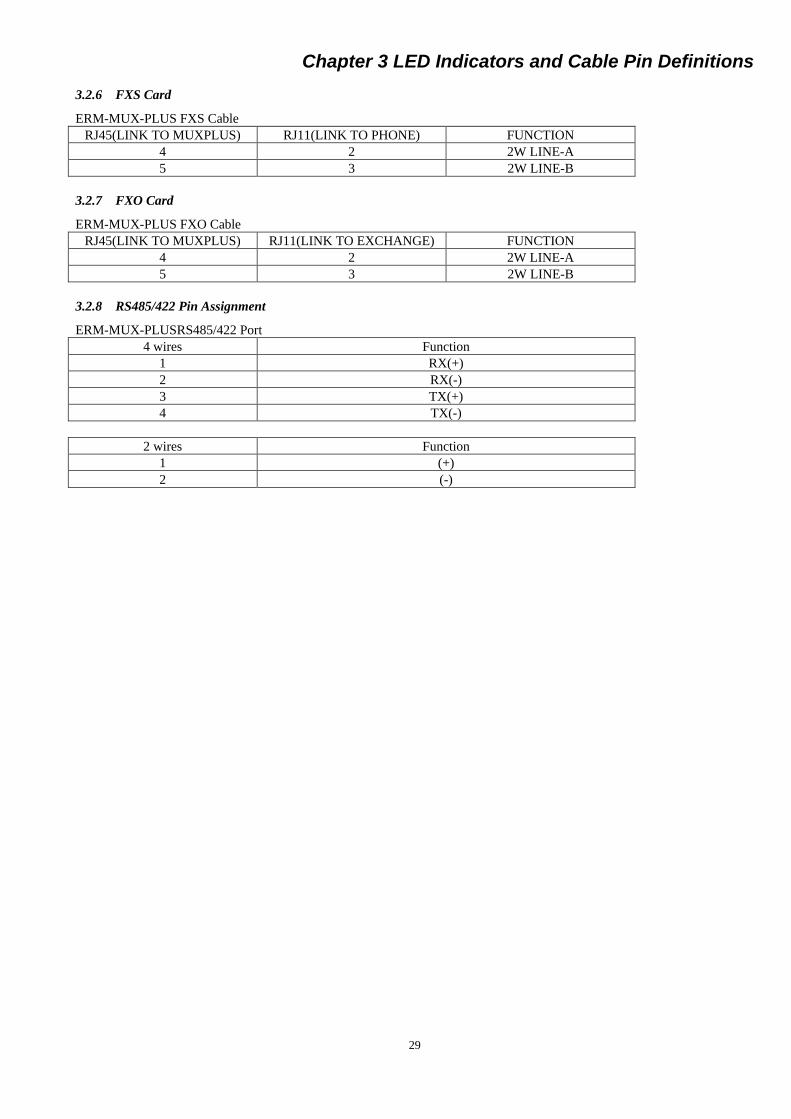
3.2.6 FXS Card
ERM-MUX-PLUS FXS Cable
RJ45(LINK TO MUXPLUS) RJ11(LINK TO PHONE) FUNCTION
4 2 2W LINE-A
5 3 2W LINE-B
3.2.7 FXO Card
ERM-MUX-PLUS FXO Cable
RJ45(LINK TO MUXPLUS) RJ11(LINK TO EXCHANGE) FUNCTION
4 2 2W LINE-A
5 3 2W LINE-B
3.2.8 RS485/422 Pin Assignment
ERM-MUX-PLUSRS485/422 Port
4 wires Function
1 RX(+)
2 RX(-)
3 TX(+)
4 TX(-)
2 wires Function
1 (+)
2 (-)

Chapter 3 LED Indicators and Cable Pin Definitions
30
This page was left blank intentionally.

Chapter 4 Hardware Settings
31
Chapter 4 Hardware Settings
When setting the ERM-MUX/PLUS via NMP management system or Terminal console process, the setting parameters are
stored in non-volatile RAM. In addition to the soft settings, some PCB cards require some settings of DIP switches or jumpers.
4.1 E1 Card
SW2: All "ON" places E1 card interface impedance at 75 ohm for BNC.
All "OFF" places E1 card interface impedance at 120 ohm for RJ-45
4.1 E1 Card
4.2 N64K/V35 Card
Interface selection
CH1 Jumper: SW7, SW15, SW3, SW11, SW19
CH2 Jumper: SW5, SW13, SW1, SW9, SW7
CH3 Jumper: SW6, SW14, SW2, SW10, SW18
CH4 Jumper: SW8, SW16, SW4, SW12, SW20
When jumpers set on the RS530 side, the channel works as RS530, X.21, or RS449.
When jumpers set on the V35 side, the channel works as V35.
4.2 N64 Card
EMP_8E1- V1.1 6 8 7 5
6 8 7 5
6 8 7 5
6 8 7 5
6 8 7 5
6 8 7 5
6 8 7 5
6 8 7 5 EMP_8E1- SUB_V1.1
SW2
SW2
SW2
SW2
SW2
SW2
SW2
SW2
DIP
Jumpers
RS530 V.35
RS530 V.35
RS530 V.35
RS530 V.35
MUX_N64(V35)_V1.0
Chapter 4 Hardware Settings
32
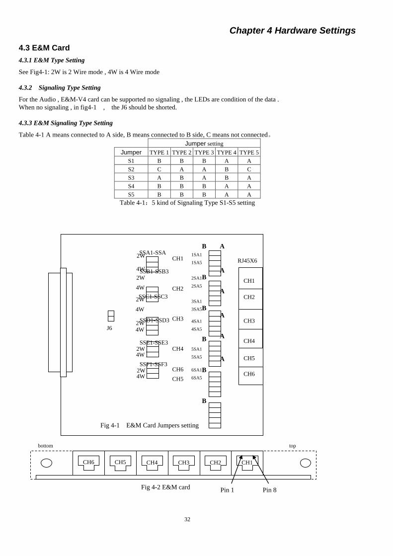
4.3 E&M Card
4.3.1 E&M Type Setting
See Fig4-1: 2W is 2 Wire mode , 4W is 4 Wire mode
4.3.2 Signaling Type Setting
For the Audio , E&M-V4 card can be supported no signaling , the LEDs are condition of the data .
When no signaling , in fig4-1 , the J6 should be shorted.
4.3.3 E&M Signaling Type Setting
Table 4-1 A means connected to A side, B means connected to B side, C means not connected。
Jumper setting
Jumper TYPE 1 TYPE 2 TYPE 3 TYPE 4 TYPE 5
S1 B B B A A
S2 C A A B C
S3 A B A B A
S4 B B B A A
S5 B B B A A
Table 4-1:5 kind of Signaling Type S1-S5 setting
1SA1
1SA5
2W
4W
2SA1
2SA5
3SA1
3SA5
CH1
CH2
CH3
A
CH4
CH2
CH3
CH1
RJ45X6
SSA1-SSA
3
4SA1
4SA5
CH4
CH5
CH6
Pin 1 Fig 4-2 E&M card Pin 8
CH1 CH2 CH3 CH4 CH5 CH6
top bottom
5SA1
5SA5
CH5
6SA1
6SA5
CH6
A
A
A
A
A
B
B
B
B
B
B
J6
Fig 4-1 E&M Card Jumpers setting
2W
4W
SSB1-SSB3
2W
4W
SSC1-SSC3
2W 4W
SSD1-SSD3
2W 4W
SSE1-SSE3
2W 4W
SSF1-SSF3

Chapter 5 Console Operation
33
Chapter 5 Console Operation
This chapter introduces how to configure the ERM-MUX/PLUS using console terminal mode.
5.1 Initial Setup
Before beginning, please connect ERM-MUX/PLUS to the serial port of a standard terminal or emulation terminal, such as
HyperTerminal program on a Windows® PC. The parameter settings for HyperTerminal are: baud rate 9600 bps (bits per
second), data bits 8, stop bit 1, no parity check, and no flow control.
Note: When there are two CPU cards, one CPU card will be the backup to the active one automatically after booting the system.
Please connect the terminal to the active CPU from the front panel.
5.1.1 Boot
If the system has already booted, initialize configuration. If the system has been set up, load the parameters saved in computer
and configure the system. The terminal will display:
INIT WAIT ...... SYSTEM PARAMETER SAVE OK!
The system will search for each card, and set up with current parameters. If there are no current parameters, omit this step.
INITIALIZING, PLEASE WAIT ...... Then it searches each module, and sets system by current parameters (if there are no current parameters, this item won't show)
START CONFIG..............................
C/B :BOARD SET OK E1A 8*E1 :BOARD SET OK
E1B 8*E1 :BOARD SET OK
slot 02 A/SYNC-128K :BOARD SET OK slot 03 E&M :BOARD SET OK
slot 04 FXO :BOARD SET OK
slot 06 FXS :BOARD SET OK
slot 01 N64K-V35 :BOARD NEW ADDED slot 05 G703-64K :BOARD NEW ADDED
Next will display the configuration and status of each card.
C/B NORMAL FAN 1 NORMAL FAN 2 NORMAL FAN 3 NORMAL FAN 4 NORMAL FAN 5 NORMAL POWER A NORMAL POWER B EMPTY CPU A NORMAL E1A 8*E1 NORMAL … … E1B 8*E1 NORMAL … … SLOT 01 N64/V35 NORMAL … … SLOT 02 A/SYNC-128K NORMAL … … SLOT 03 E&M NORMAL … …
Chapter 5 Console Operation
34
SLOT 04 FXO NORMAL … … SLOT 05 G703-64K NORMAL … … SLOT 06 FXS NORMAL
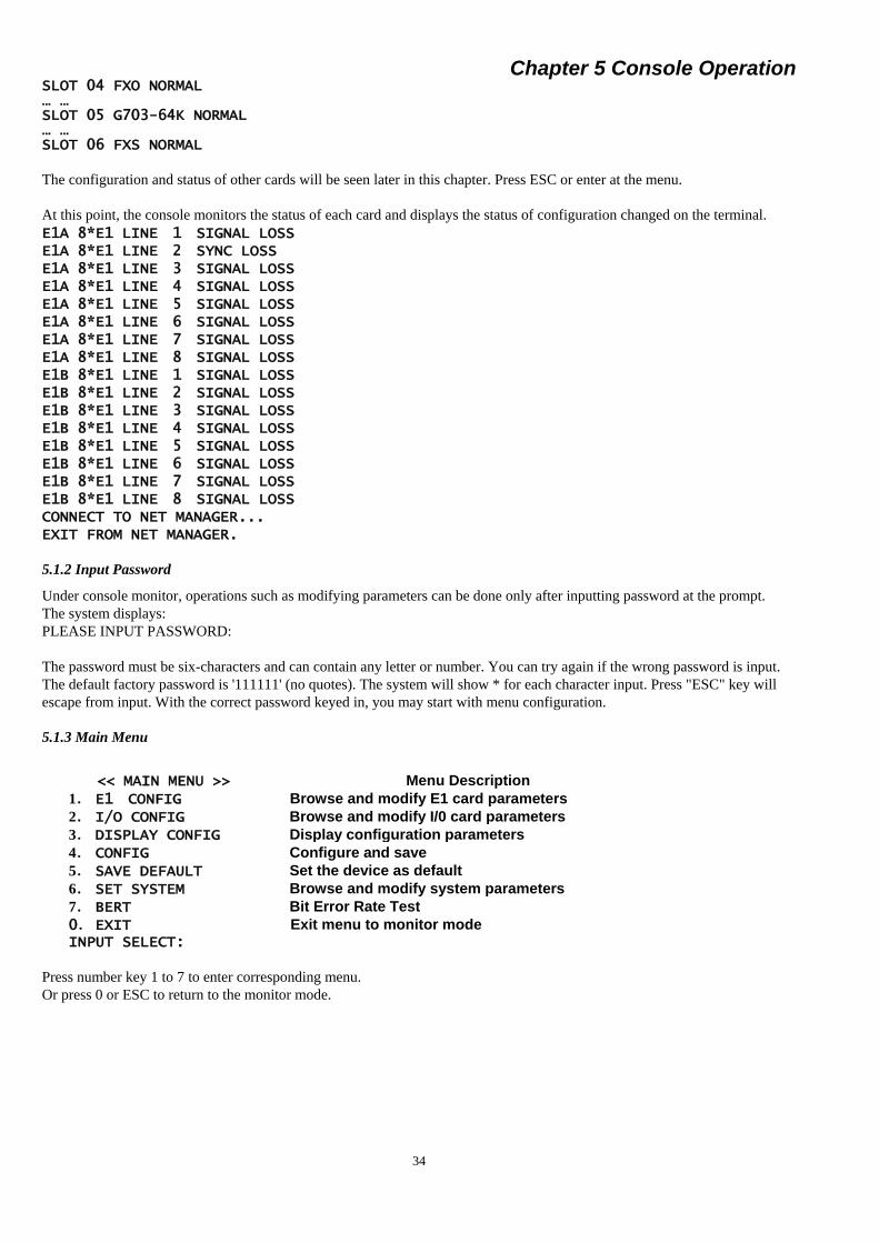
The configuration and status of other cards will be seen later in this chapter. Press ESC or enter at the menu.
At this point, the console monitors the status of each card and displays the status of configuration changed on the terminal.
E1A 8*E1 LINE 1 SIGNAL LOSS E1A 8*E1 LINE 2 SYNC LOSS E1A 8*E1 LINE 3 SIGNAL LOSS E1A 8*E1 LINE 4 SIGNAL LOSS E1A 8*E1 LINE 5 SIGNAL LOSS E1A 8*E1 LINE 6 SIGNAL LOSS E1A 8*E1 LINE 7 SIGNAL LOSS E1A 8*E1 LINE 8 SIGNAL LOSS E1B 8*E1 LINE 1 SIGNAL LOSS E1B 8*E1 LINE 2 SIGNAL LOSS E1B 8*E1 LINE 3 SIGNAL LOSS E1B 8*E1 LINE 4 SIGNAL LOSS E1B 8*E1 LINE 5 SIGNAL LOSS E1B 8*E1 LINE 6 SIGNAL LOSS E1B 8*E1 LINE 7 SIGNAL LOSS E1B 8*E1 LINE 8 SIGNAL LOSS CONNECT TO NET MANAGER... EXIT FROM NET MANAGER.
5.1.2 Input Password
Under console monitor, operations such as modifying parameters can be done only after inputting password at the prompt.
The system displays:
PLEASE INPUT PASSWORD:
The password must be six-characters and can contain any letter or number. You can try again if the wrong password is input.
The default factory password is '111111' (no quotes). The system will show * for each character input. Press "ESC" key will
escape from input. With the correct password keyed in, you may start with menu configuration.
5.1.3 Main Menu
<< MAIN MENU >> Menu Description
1. E1 CONFIG Browse and modify E1 card parameters
2. I/O CONFIG Browse and modify I/0 card parameters
3. DISPLAY CONFIG Display configuration parameters
4. CONFIG Configure and save
5. SAVE DEFAULT Set the device as default
6. SET SYSTEM Browse and modify system parameters
7. BERT Bit Error Rate Test
0. EXIT Exit menu to monitor mode INPUT SELECT:
Press number key 1 to 7 to enter corresponding menu.
Or press 0 or ESC to return to the monitor mode.

Chapter 5 Console Operation
35
5.2 Set E1 card
Press 1 from the main menu to configure the E1 card. If no E1 card is found, the display shows:
NO E1 CARD
If the types of two E1 cards are inconsistent, the display shows: INPUT E1 LINE(1-8):1 Press number key 1 to 8 to enter a corresponding sub menu of E1 channel. Press 0 or ESC to return to the upper menu.
Once selected, the E1 card will be checked, the configuration displayed, and current status of E1 card shown.
E1-1 current parameter: LINE:CCS,CRC4 DISABLE,NOLOOP,HDB3,RECEIVE JITTA NMP:NMP DISABLE,0 BERT:BERT DISABLE,2E11-1,NONE
E1 channel menu display
<< E1-1 CONFIG >> Menu Description
1. E1 FRAME/TS0 PASS Set frame mode and timeslot 0 bypass
2. E1 CRC Set CRC-4 mode
3. E1 LOOP Set loop back test mode
4. CODE Set E1 line code
5. JITTER Set E1 JITTER
6. TIMESLOT CROSS Set timeslot cross connections
0. EXIT Return to the upper menu
INPUT SELECT:
Press number key 1 to 6 to enter the corresponding sub menu.
Press 0 or ESC return to the upper menu.
5.2.1 Set Frame Mode
From the E1 channel menu, select 1 to enter frame mode configuration. The menu displays:
<< E1-1 CONFIG - FRAME/TS0 >> Menu Description
*1. CCS(31 SLOTS) Sets the E1 framing
2. CAS (30 SLOTS)
3. CCS TS0 PASS(31 SLOTS) (CCS+TimeSlot0 Pass)
4. CAS TS0 PASS(30 SLOTS) (CAS+ TimeSlot0 Pass)
0. EXIT Return to the upper menu
INPUT SELECT:
('*' indicates the current setting.)
Press number 1 to 4 to configure and press 0 or ESC return to the upper menu. After selecting a number, the menu will refresh,
and '*' will indicate the new setting.
5.2.2 Set CRC Mode
From the E1 channel menu, select 2 to enter CRC mode configuration. The menu displays:
<< E1-1 CONFIG - CRC4 >> Menu Description
1.CRC4 ENABLE With CRC check
*2.CRC4 DISABLE No CRC check
0. EXIT Return to the upper menu
INPUT SELECT:
('*' indicates the current setting.)
Press number 1 to 2 to configure and press 0 or ESC return to the upper menu. After selecting a number, the menu will refresh,
and '*' will indicate the new setting.
Chapter 5 Console Operation
36
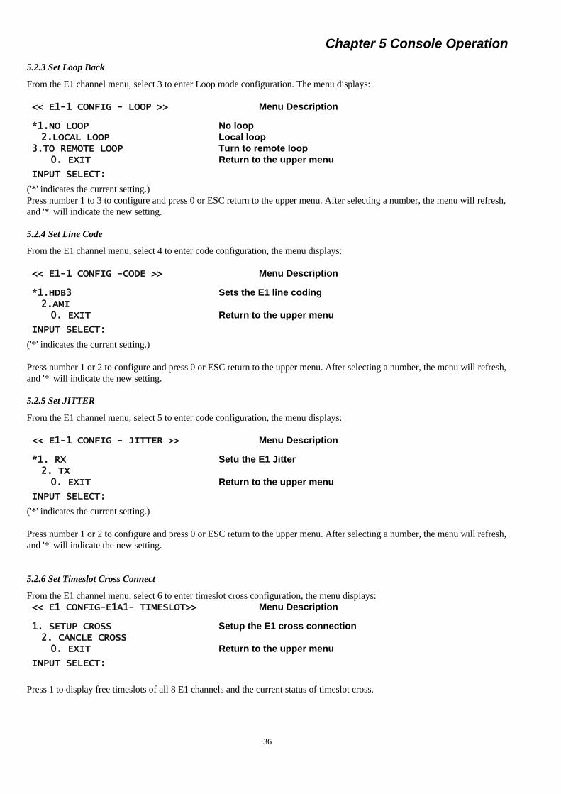
5.2.3 Set Loop Back
From the E1 channel menu, select 3 to enter Loop mode configuration. The menu displays:
<< E1-1 CONFIG - LOOP >> Menu Description
*1.NO LOOP No loop
2.LOCAL LOOP Local loop
3.TO REMOTE LOOP Turn to remote loop
0. EXIT Return to the upper menu
INPUT SELECT:
('*' indicates the current setting.)
Press number 1 to 3 to configure and press 0 or ESC return to the upper menu. After selecting a number, the menu will refresh,
and '*' will indicate the new setting.
5.2.4 Set Line Code
From the E1 channel menu, select 4 to enter code configuration, the menu displays:
<< E1-1 CONFIG -CODE >> Menu Description
*1.HDB3 Sets the E1 line coding
2.AMI
0. EXIT Return to the upper menu
INPUT SELECT:
('*' indicates the current setting.)
Press number 1 or 2 to configure and press 0 or ESC return to the upper menu. After selecting a number, the menu will refresh,
and '*' will indicate the new setting.
5.2.5 Set JITTER
From the E1 channel menu, select 5 to enter code configuration, the menu displays:
<< E1-1 CONFIG - JITTER >> Menu Description
*1. RX Setu the E1 Jitter
2. TX
0. EXIT Return to the upper menu
INPUT SELECT:
('*' indicates the current setting.)
Press number 1 or 2 to configure and press 0 or ESC return to the upper menu. After selecting a number, the menu will refresh,
and '*' will indicate the new setting.
5.2.6 Set Timeslot Cross Connect
From the E1 channel menu, select 6 to enter timeslot cross configuration, the menu displays:
<< E1 CONFIG-E1A1- TIMESLOT>> Menu Description
1. SETUP CROSS Setup the E1 cross connection
2. CANCLE CROSS
0. EXIT Return to the upper menu
INPUT SELECT:
Press 1 to display free timeslots of all 8 E1 channels and the current status of timeslot cross.
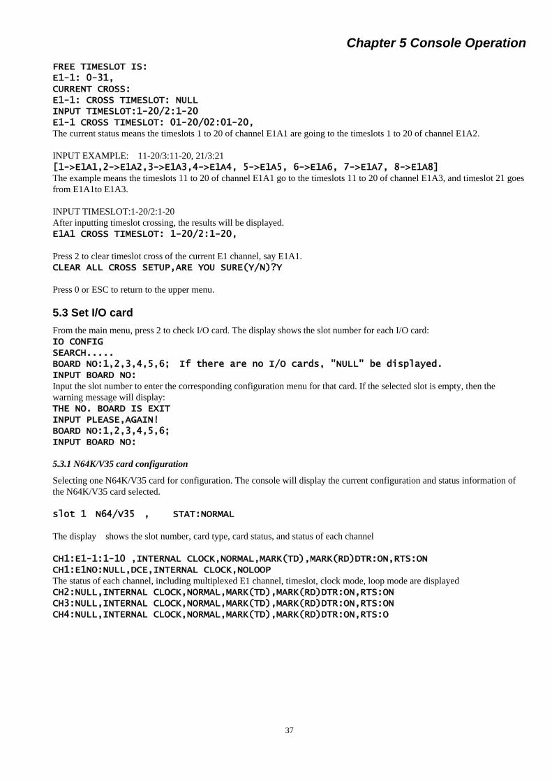
Chapter 5 Console Operation
37
FREE TIMESLOT IS: E1-1: 0-31, CURRENT CROSS: E1-1: CROSS TIMESLOT: NULL INPUT TIMESLOT:1-20/2:1-20 E1-1 CROSS TIMESLOT: 01-20/02:01-20, The current status means the timeslots 1 to 20 of channel E1A1 are going to the timeslots 1 to 20 of channel E1A2.
INPUT EXAMPLE: 11-20/3:11-20, 21/3:21
[1->E1A1,2->E1A2,3->E1A3,4->E1A4, 5->E1A5, 6->E1A6, 7->E1A7, 8->E1A8] The example means the timeslots 11 to 20 of channel E1A1 go to the timeslots 11 to 20 of channel E1A3, and timeslot 21 goes
from E1A1to E1A3.
INPUT TIMESLOT:1-20/2:1-20
After inputting timeslot crossing, the results will be displayed.
E1A1 CROSS TIMESLOT: 1-20/2:1-20,
Press 2 to clear timeslot cross of the current E1 channel, say E1A1.
CLEAR ALL CROSS SETUP,ARE YOU SURE(Y/N)?Y
Press 0 or ESC to return to the upper menu.
5.3 Set I/O card
From the main menu, press 2 to check I/O card. The display shows the slot number for each I/O card:
IO CONFIG SEARCH..... BOARD NO:1,2,3,4,5,6; If there are no I/O cards, "NULL" be displayed. INPUT BOARD NO: Input the slot number to enter the corresponding configuration menu for that card. If the selected slot is empty, then the
warning message will display:
THE NO. BOARD IS EXIT INPUT PLEASE,AGAIN! BOARD NO:1,2,3,4,5,6; INPUT BOARD NO:
5.3.1 N64K/V35 card configuration
Selecting one N64K/V35 card for configuration. The console will display the current configuration and status information of
the N64K/V35 card selected.
slot 1 N64/V35 , STAT:NORMAL
The display shows the slot number, card type, card status, and status of each channel
CH1:E1-1:1-10 ,INTERNAL CLOCK,NORMAL,MARK(TD),MARK(RD)DTR:ON,RTS:ON CH1:E1NO:NULL,DCE,INTERNAL CLOCK,NOLOOP The status of each channel, including multiplexed E1 channel, timeslot, clock mode, loop mode are displayed
CH2:NULL,INTERNAL CLOCK,NORMAL,MARK(TD),MARK(RD)DTR:ON,RTS:ON CH3:NULL,INTERNAL CLOCK,NORMAL,MARK(TD),MARK(RD)DTR:ON,RTS:ON CH4:NULL,INTERNAL CLOCK,NORMAL,MARK(TD),MARK(RD)DTR:ON,RTS:O

Chapter 5 Console Operation
38
5.3.2 N64K/V35 menu display
<< I/O CONFIG-N64K-V35 >> Menu Description
1. CHANNEL 1 Set channel 1
2. CHANNEL 2 Set channel 2
3. CHANNEL 3 Set channel 3
4. CHANNEL 4 Set channel 4
0. EXIT Return to the I/O card configuration
INPUT SELECT:1
Press 0 or ESC to return to the I/O card selection menu. Press 1-4 to enter SYNC channel configuration. (The same
configuration menus apply for channels 1 to 4).
5.3.3 N64K/V35 channel menu display
Select a channel, for example channel 1, and enter configuration menu. The menu displays the following:
<< IO CONFIG-N64K-V35-CHANNEL 1 >>
Menu Description
1. E1/TIMESLOT Set multiplex E1 channel/timeslot
2. LOOP Set loop
3. CLOCK Set clock mode
0.EXIT Return to the upper menu
INPUT SELECT:
Press 0 or ESC return to the upper menu. Press 1-3 to enter the corresponding configuration item.
5.3.4 Set multiplex E1 number
Press 1 to enter the configuration menu of setting E1 channel. The menu displays:
The display also shows any current status if there are any timeslots connection from any E1.
CURRENT:E1A1-NULL
INPUT EXAMPLE: 3-9,11
INPUT TIMESLOT: 3-9,11
One or more idle timeslots can be assigned to one N64 I/O channel:
You can assign one single timeslot number or consecutive timeslot numbers. For example, "5,10-20,27" means the
timeslots 5, 10 to 20, and 27 of E1A1 (selected earlier) are assigned to CH1 of I/O card. Input the idle timeslot number(s) and
press Enter to confirm. Return to the upper menu.
FREE TIMESLOT IS: Menu Description
1: 1-31, E1-1 free timeslot
2: 1-31, E1-2 free timeslot
3: 1-31, E1-3 free timeslot
4: 1-31, E1-4 free timeslot
5: 1-31, E1-5 free timeslot
6: 1-31, E1-6 free timeslot
7: 1-31, E1-7 free timeslot
8: 1-31, E1-8 free timeslot
CURRENT:E1-1:1-10
USAGE: 3-9,11
INPUT E1 LINE(1-8)

Chapter 5 Console Operation
39
If the input timeslot has already been assigned previously, the system will prompt:
Press 0 or ESC return to the upper menu. Press 1-8 to enter the E1 configuration item THE TIMESLOT ALREADY USED! INPUT AGAIN! INPUT TIMESLOT:
If no timeslot number has been input, then press Enter or ESC to return to the upper menu.
5.3.5 Set loop mode
Press 4 to set loop mode of I/O channel. The menu displays
<< IO CONFIG-N64K-V35-CHANNEL 1-LOOPBACK >> Menu Description
*1. NORMAL Without loop
2. LOCAL LOOP
3. REMOTE LOOP
4. LOOP
0. EXIT Return to the upper menu
INPUT SELECT:0
('*'indicates the current setting.)
Press 1 - 4 to select the loop back configuration. Press 0 or ESC to return to the upper menu. After key 1 -4 is pressed, the
menu will be shown again, and '*' will indicate the new setting.
5.3.6 Set clock mode
Press 6 to set the clock mode of the I/O channel. The menu displays
<< I/O CONFIG-N64/V35-CHANNEL 1-CLOCK >> Menu Description
*1. INTERNAL Set internal clock
2. EXTERNAL Set external clock
0. EXIT Return to the upper menu
INPUT SELECT:0
('*'indicates the current setting.)
Press 1 or 2 to select the clock mode configuration. Press 0 or ESC to return to the upper menu. After keying 1 or 2, the menu
will be shown again, and '*' will indicate the new setting.
5.4 Set RS-232 Card
Please refer to N64K/V35 configuration settings which are applied the same way to RS-232 card.
5.5 Set G703-64K Card
When entering the G703-64K card configuration under the I/O card sub-menu, the display will show the current configuration
and status information of the G703-64K card selected.
slot 5 G703-64K STAT:NORMAL Slot number card type card status
CH1:NOE1:NULL,INTERNAL CLOCK,NOLOOP,NORMAL,SIGNAL LOSS The display shows the status of each channel, including multiplexed E1 channel, timeslot, clock mode, loop mode.
CH2:NOE1:NULL,INTERNAL CLOCK,NOLOOP,NORMAL,SIGNAL LOSS CH3:NOE1:NULL,INTERNAL CLOCK,NOLOOP,NORMAL,SIGNAL LOSS CH4:NOE1:NULL,INTERNAL CLOCK,NOLOOP,NORMAL,SIGNAL LOSS
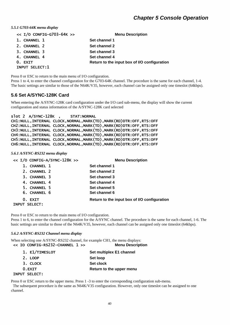
Chapter 5 Console Operation
40
5.5.1 G703-64K menu display
<< I/O CONFIG-G703-64K >> Menu Description
1. CHANNEL 1 Set channel 1
2. CHANNEL 2 Set channel 2
3. CHANNEL 3 Set channel 3
4. CHANNEL 4 Set channel 4
0. EXIT Return to the input box of I/O configuration
INPUT SELECT:1
Press 0 or ESC to return to the main menu of I/O configuration.
Press 1 to 4, to enter the channel configuration for the G703-64K channel. The procedure is the same for each channel, 1-4.
The basic settings are similar to those of the N64K/V35, however, each channel can be assigned only one timeslot (64kbps).
5.6 Set A/SYNC-128K Card
When entering the A/SYNC-128K card configuration under the I/O card sub-menu, the display will show the current
configuration and status information of the A/SYNC-128K card selected
slot 2 A/SYNC-128K , STAT:NORMAL CH1:NULL,INTERNAL CLOCK,NORMAL,MARK(TD),MARK(RD)DTR:OFF,RTS:OFF CH2:NULL,INTERNAL CLOCK,NORMAL,MARK(TD),MARK(RD)DTR:OFF,RTS:OFF CH3:NULL,INTERNAL CLOCK,NORMAL,MARK(TD),MARK(RD)DTR:OFF,RTS:OFF CH4:NULL,INTERNAL CLOCK,NORMAL,MARK(TD),MARK(RD)DTR:OFF,RTS:OFF CH5:NULL,INTERNAL CLOCK,NORMAL,MARK(TD),MARK(RD)DTR:OFF,RTS:OFF CH6:NULL,INTERNAL CLOCK,NORMAL,MARK(TD),MARK(RD)DTR:OFF,RTS:OFF
5.6.1 A/SYNC-RS232 menu display
<< I/O CONFIG-A/SYNC-128K >> Menu Description
1. CHANNEL 1 Set channel 1
2. CHANNEL 2 Set channel 2
3. CHANNEL 3 Set channel 3
4. CHANNEL 4 Set channel 4
5. CHANNEL 5 Set channel 5
6. CHANNEL 6 Set channel 6
0. EXIT Return to the input box of I/O configuration
INPUT SELECT:
Press 0 or ESC to return to the main menu of I/O configuration.
Press 1 to 6, to enter the channel configuration for the A/SYNC channel. The procedure is the same for each channel, 1-6. The
basic settings are similar to those of the N64K/V35, however, each channel can be assigned only one timeslot (64kbps).
5.6.2 A/SYNC-RS232 Channel menu display
When selecting one A/SYNC-RS232 channel, for example CH1, the menu displays:
<< IO CONFIG-RS232-CHANNEL 1 >> Menu Description
1. E1/TIMESLOT Set multiplex E1 channel
2. LOOP Set loop
3. CLOCK Set clock
0.EXIT Return to the upper menu
INPUT SELECT:
Press 0 or ESC return to the upper menu. Press 1 -3 to enter the corresponding configuration sub-menu.
The subsequent procedure is the same as N64K/V35 configuration. However, only one timeslot can be assigned to one
channel.
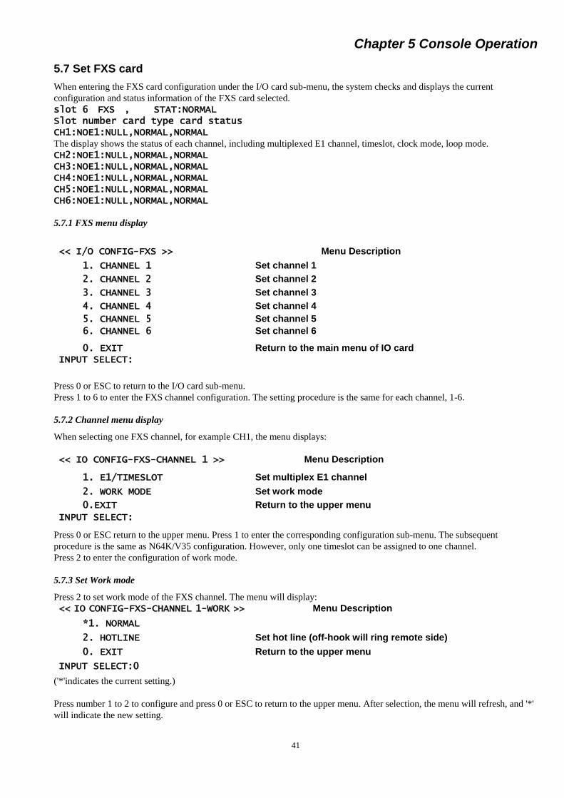
Chapter 5 Console Operation
41
5.7 Set FXS card
When entering the FXS card configuration under the I/O card sub-menu, the system checks and displays the current
configuration and status information of the FXS card selected.
slot 6 FXS , STAT:NORMAL Slot number card type card status CH1:NOE1:NULL,NORMAL,NORMAL The display shows the status of each channel, including multiplexed E1 channel, timeslot, clock mode, loop mode.
CH2:NOE1:NULL,NORMAL,NORMAL CH3:NOE1:NULL,NORMAL,NORMAL CH4:NOE1:NULL,NORMAL,NORMAL CH5:NOE1:NULL,NORMAL,NORMAL CH6:NOE1:NULL,NORMAL,NORMAL
5.7.1 FXS menu display
<< I/O CONFIG-FXS >> Menu Description
1. CHANNEL 1 Set channel 1
2. CHANNEL 2 Set channel 2
3. CHANNEL 3 Set channel 3
4. CHANNEL 4 Set channel 4
5. CHANNEL 5 Set channel 5
6. CHANNEL 6 Set channel 6
0. EXIT Return to the main menu of IO card
INPUT SELECT:
Press 0 or ESC to return to the I/O card sub-menu.
Press 1 to 6 to enter the FXS channel configuration. The setting procedure is the same for each channel, 1-6.
5.7.2 Channel menu display
When selecting one FXS channel, for example CH1, the menu displays:
<< IO CONFIG-FXS-CHANNEL 1 >> Menu Description
1. E1/TIMESLOT Set multiplex E1 channel
2. WORK MODE Set work mode
0.EXIT Return to the upper menu
INPUT SELECT:
Press 0 or ESC return to the upper menu. Press 1 to enter the corresponding configuration sub-menu. The subsequent
procedure is the same as N64K/V35 configuration. However, only one timeslot can be assigned to one channel.
Press 2 to enter the configuration of work mode.
5.7.3 Set Work mode
Press 2 to set work mode of the FXS channel. The menu will display:
<< IO CONFIG-FXS-CHANNEL 1-WORK >> Menu Description
*1. NORMAL
2. HOTLINE Set hot line (off-hook will ring remote side)
0. EXIT Return to the upper menu
INPUT SELECT:0
('*'indicates the current setting.)
Press number 1 to 2 to configure and press 0 or ESC to return to the upper menu. After selection, the menu will refresh, and '*'
will indicate the new setting.

Chapter 5 Console Operation
42
5.8 Set FXO Card
Please refer to FXS configuration menu. The settings for FXO are the same, with the exception that there is no work mode
setting for the FXO cards. (Only FXS supports the 'hot line' function.).
5.9 Set E&M Card
When entering the E&M card configuration under the I/O card sub-menu, the system checks and displays the current
configuration and status information of the E&M card selected
slot 3 E&M STATE:NORMAL Slot number card type card status CH1:NOE1:NULL,NORMAL,1.5db,2.0db The display shows the status of each channel, including multiplexed E1 channel, timeslot, clock mode, loop mode, TX LEVEL,
RX LEVEL
CH2:NOE1:NULL,NORMAL,0.0db,0.0db CH3:NOE1:NULL,NORMAL,0.0db,0.0db CH4:NOE1:NULL,NORMAL,0.0db,0.0db CH5:NOE1:NULL,NORMAL,0.0db,0.0db CH6:NOE1:NULL,NORMAL,0.0db,0.0db
5.9.1 E&M MENU DISPLAY
<< I/O CONFIG-E&M >> Menu Description
1. CHANNEL 1 Set channel 1
2. CHANNEL 2 Set channel 2
3. CHANNEL 3 Set channel 3
4. CHANNEL 4 Set channel 4
5. CHANNEL 5 Set channel 5
6. CHANNEL 6 Set channel 1
0. EXIT Return to the main menu of IO card
INPUT SELECT:
Press 0 or ESC to return to the I/O card sub-menu.
Press 1 to 6 to enter the E&M channel configuration. The setting procedure is the same for each channel, 1-6.
5.9.2 E&M Channel menu display
When selecting one E&M channel, for example CH1, the menu displays:
<< I/O CONFIG-E&M-CHANNEL 1 >> Menu Description
1. E1/TIMESLOT Set multiplex E1 channel
2. LOOP
3. TX LEVEL
4. RX LEVEL
0.EXIT Return to the upper menu
INPUT SELECT:
Press 0 or ESC return to the upper menu. Press 1 or 2 to enter the corresponding configuration sub-menu. The subsequent
procedure is the same as N64K/V35 configuration. However, only one timeslot can be assigned to one channel.
Press 3 or 4 to enter the TX/RX level
Current Tx level:1.5db INPUT DB(-20...+8):
Note : ERM-MUX-PLUS-E&M(4) TX INPUT DB range is (TX -20dB ~ +8dB)
ERM-MUX-PLUS-E&M+(4) TX INPUT DB range is (TX -12dB ~ +16dB)

Chapter 5 Console Operation
43
5.10 Set X.50 Card
When entering the X.50 card configuration under the I/O card sub-menu, the system checks and displays the current
configuration and status information of the X.50 card selected
5.11 Set ET100 Card
When entering the ET100 card configuration under the I/O card sub-menu, the system checks and displays the current
configuration and status information of the ET100 card selected
slot 6 ET100 STATE:NORMAL CH1:NULL, ANEG ENABLE, FULL, 100M, FLOW CONTROL DISABLE, AUTO MAC ENABLE, NOLOOP CH2:NULL, ANEG ENABLE, FULL, 100M, FLOW CONTROL DISABLE, AUTO MAC ENABLE, NOLOOP <<I/O CONFIG-ET100
1. CHANNEL 1 2. CHANNEL 2 0. EXIT
INPUT SELECT:1
<< I/O CONFIG-ET100-CHANNEL 1>>
1. E1/TIMESLOT
2. AUTO-NEGOT
3. COMMUNICATION MODE
4. SPEED
5. FLOW CONTROL
6. MAC FILTERING
7. LOCAL LOOP
0. EXIT
INPUT SELECT:
Press 0 or ESC return to the upper menu.
Press 1 ~ 7 to enter the corresponding configuration sub-menu.
5.11.1 Set multiplex E1 number
Press 1 to display the configuration menu of setting E1 channel. The menu displays:
Select E1 line (1-8), Press 0 or ESC return to the upper menu
5.11.2 Set Auto Negotiation
Press 2 to display the configuration menu of setting Auto Negotiation. The menu displays:
INPUT SELECT : 2
FREE TIMESLOT IS: Menu Description
1: 1-31, E1-1 free timeslot
2: 1-31, E1-2 free timeslot
3: 1-31, E1-3 free timeslot
4: 1-31, E1-4 free timeslot
5: 1-31, E1-5 free timeslot
6: 1-31, E1-6 free timeslot
7: 1-31, E1-7 free timeslot
8: 1-31, E1-8 free timeslot
CURRENT:E1-1:1-10 ET-100-channel used E1 time slot
USAGE: 3-9,11
INPUT E1 LINE(1-8)

Chapter 5 Console Operation
44
<< I/O CONFIG-ET100-CHANNEL 1-AUTO NEGOTIATION >>
1. ENABLE
2. DISABLE
0. EXIT
INPUT SELECT:
5.11.3 Set Full / Half Duplex
Press 3 to display the configuration menu of setting Full/Half duplex. The menu displays:
INPUT SELECT : 3
<< I/O CONFIG-ET100-CHANNEL 1-COMMUNICATION MODE >>
1.FULL
2.HALF
0.EXIT
INPUT SELECT :
5.11.4 Set UTP Port Speed
Press 4 to display the configuration menu of setting UTP Port Speed. The menu displays:
INPUT SELECT : 4
<< I/O CONFIG-ET100-CHANNEL 1-SPEED >>
1.100M
2.10M
0.EXIT
INPUT SELECT :
5.11.5 Set Flow Control
Press 5 to display the configuration menu of setting Flow Control. The menu displays:
INPUT SELECT : 5
<< I/O CONFIG-ET100-CHANNEL 1-FLOW CONTROL >>
1.DISABLE
2.ENABLE
0.EXIT
INPUT SELECT :
5.11.6 Set MAC FILTERING
Press 6 to display the configuration menu of setting MAC FILTERING. The menu displays:
INPUT SELECT : 6
<< I/O CONFIG-ET100-CHANNEL 1-MAC FILTERING >>
1.ENABLE
2.DISABLE
0.EXIT
INPUT SELECT :
5.11.7 Set Local Loop
Press 7 to display the configuration menu of setting Local Loop. The menu displays:
INPUT SELECT : 7
<< I/O CONFIG-ET100-CHANNEL 1-Local Loop >>
1.NO LOOP
2.LOOP
0.EXIT
INPUT SELECT :

Chapter 5 Console Operation
45
5.12 Set RS485/422 Card
When entering the RS485/422 card configuration under the I/O card sub-menu, the system checks and displays the current
configuration and status information of the ET100 card selected
INPUT BOARD NO:6 Slot 6 RS485 STAT:NORMAL CH1:E1-2 : 1- 6, NORMAL, MARK(TD), MARK(RD) CH2:E1-2 : 7-12, NORMAL, MARK(TD), MARK(RD) CH3:E1-2 :13-15, 17-19, NORMAL, MARK(TD), MARK(RD) CH4:E1-2 :20-25, NORMAL, MARK(TD), MARK(RD) CH5:E1-2 :26-27, NORMAL, MARK(TD), MARK(RD) CH6:E1-2 :28-30, NORMAL, MARK(TD), MARK(RD)
5.12.1 RS485 Configuration Menu
<< I/O CONFIG-RS485 >>
1.CHANNEL 1
2.CHANNEL 2
3.CHANNEL 3
4.CHANNEL 4
5.CHANNEL 5
6.CHANNEL 6
0.EXIT
INPUT SELECT
Press 0 or ESC return to the I/O configuration sub-menu.
Press 1 ~ 6 to enter the RS485 channels configuration.
5.12.2 RS485 Channel Configuration Display
When entering the RS485 card configuration under the RS485 channel configuration sub-menu (CHANNEL ONE FOR
EXAMPLE), the system checks and displays the current configuration and status information of the RS485 channel
<< I/O CONFIG-RS485-CHANNEL 1 >>
1.E1/TIMESLOT
2.LOOP
0.EXIT
INPUT SELECT
Press 0 or ESC return to the upper menu.
Press 1 or 2 to enter the RS485 channel configuration
5.12.3 Set multiplex E1 number
Press 1 to display the configuration menu of setting E1 channel. The menu displays:

Chapter 5 Console Operation
46
Select E1 line (1-8), Press 0 or ESC return to the upper menu
5.12.4 Set Loopback
Press 2 to display the configuration menu of setting Loopback. The menu displays:
<< I/O CONFIG-RS485-CHANNEL 1-LOOPBACK >>
*1.NORMAL
2.LOCAL LOOP
3. REMOTE LOOP
4.LOOP
0.EXIT
INPUT SELECT : 0
(‘*” : current setting)
Press 0 or ESC return to the upper menu.
Press 1 ~ 4 to change Loopback configuration (“*” will follow the new setting)
5.13 Display devices configuration
Press 3 from the main menu. The system displays the configuration and status of each module, including CPU, E1, and I/O
cards.
<< DISPLAY CONFIG >> Menu Description
1. DISPLAY BOARD DETAIL Display card configuration
2. DISPLAY WORK STATE Display device and working status of card
0. EXIT Return to the main menu
INPUT SELECT:1
Pressing 1 will show the following status:
Presence of cards
Working status
Configuration parameters
Note: The system will not automatically refresh when in "3.DISPLAY CONFIG", only in the main menu 2, 4, & 5.
Press 2 to display the working status of each plug-in module, including CPU, power, fan, E1, and I/O cards. The system will
refresh in real time. It will also display the status of G.703 external-clock device, if any is present.
Press 0 or ESC to return to the main menu.
After pressing 1, the system will display statuses in order for CPU card, E1 card and I/O cards. The following is a
configuration example.
FREE TIMESLOT IS: Menu Description
1: 1-31, E1-1 free timeslot
2: 1-31, E1-2 free timeslot
3: 1-31, E1-3 free timeslot
4: 1-31, E1-4 free timeslot
5: 1-31, E1-5 free timeslot
6: 1-31, E1-6 free timeslot
7: 1-31, E1-7 free timeslot
8: 1-31, E1-8 free timeslot
CURRENT:E1-1:1-10 RS485-channel used E1 time slot
USAGE: 3-9,11
INPUT E1 LINE(1-8)

Chapter 5 Console Operation
47
5.14 Save Configuration
All previously outlined modified configurations are saved temporarily in volatile ram. If the chassis is powered off or the CPU
card removed, the settings will revert back to the previously saved ones. Following the settings done previously, the changes
must be written to non-volatile ram. From the main menu, item 4 CONFIG, is the utility to save all the configuration settings.
It is also highly recommended to do save settings following all major configuration sections. For example, save after doing
system configuration, save again after setting E1 parameters, and finally save after setting each I/O card. Configurations which
are modified are only saved temporarily.
After pressing 4 in the main menu, the system asks:
SYSTEM WILL BE CONFIGED,ARE YOU SURE(Y/N)?y Press N or n to escape.
Press Y or y to start saving the configuration.
START CONFIG............................. The system will now check all the new settings for each card and display the results of save configuration, success or failure. C/B :BOARD SET OK E1A 8*E1 :BOARD SET OK E1B 8*E1 :BOARD SET OK slot 1 N64/V35 :BOARD SET OK slot 2 A/SYNC-128K :BOARD SET OK slot 3 E&M :BOARD SET OK slot 4 FXO :BOARD SET OK slot 5 G703-64K :BOARD SET OK slot 6 FXS :BOARD SET OK
5.15 Reset Device Configuration to Default
After pressing 5 from the main menu, the system asks to recover to default.
YOU WILL RECOVER SYSTEM TO DEFAULT! ARE YOU SURE(Y/N)?y Press Y or y to start setting the device to default. Once started, it can not be stopped.
Please Wait.... START CONFIG............................. The system will check each card and display the result of recovery operation, success or failure.
5.16 Browse/Modify System Parameters
From the main menu select "6.SET SYSTEM". The display will show:
<< SYSTEM MENU >> Menu Description
1. VERSION Display system version
2. CLOCK Browse/ modify device clock
3. NMP CONFIG Modify NMP configuration
4. E1 BACKUP Modify backup mode of device E1
5. CHANGE PASSWORD Modify system password
6. SETUP TIME Modify device time
7. SETUP EXTEND BOX Modify EXTEND BOX
0. EXIT Return to the input box of the main menu
INPUT SELECT:1
Press 0 or ESC return to the main menu. Press 1 to 6 to get system info and/or modify the configuration.

Chapter 5 Console Operation
48
5.16.1 Display system version
Press 1 to enter the VERSION mode display menu ERM-MUX-PLUS version 4.00
5.16.2 Modify System Clock
Press 2 to enter the CLOCK mode configuration menu. The menu will display:
<< SYSTEM CONFIG-CLOCK >> Menu Description
1. INT OSC Internal OSC is source
2. IO CLOCK Set I/O as external clock
3. EXTERNAL CLOCK Set external clock
*4. E1 RECOVER CLOCK [1] E1A recover clock is source
0. EXIT Return to the upper menu
INPUT SELECT:1
('*'indicates current setting.)
Press 1 to 4 to select the desired configuration, or press 0 or ESC to return to the upper menu. After configuration change by
pressing key 1 to 4, the system will refresh the menu, and '*' will indicate the new setting. If IO card is selected for clock
source, the system will check the I/O slots for presence of a compatible clock source cards.
For example, the system might show:
IO CLOCK VAILD BOARD SLOT: slot 01 N64K-V35 slot 05 G703 slot 10 N64K-232 CURRENT IO CLOCK SLOT:NULL The listed cards are all candidates for providing clock source. If entering 5, the system will show:
INPUT SLOT NO:5
Note: Only the clock from the first channel (CH1) of the selected slot can be used to apply clock for the whole system when
the I/O card clock is used.
5.17 Modify NMP /SNMP Parameter
Please press 3 to enter "3.NMP CONFIG". The menu will display:
<< SYSTEM CONFIG-NMP >> Menu Description
1. UP TIMESLOT up timeslot of in-band NMP
2. DOWN TIMESLOT down timeslot of in-band NMP
3. DISABLE NMP Disable NMP
4. IP ADDRESS Change IP address
5. DEVICE ADDRESS Device address
6. DOWN DEVICE ADDRESS Down device address of in-band NMP
0. EXIT Return to the upper menu
INPUT SELECT:1
5.17.1 Set up timeslot of in-band NMP
Please press 1 to enter "1. UP TIMESLOT ". The menu will display:
CURRENT:E1-1:31 INPUT TIMESLOT(INPUT 0 TO CANCEL):31
5.17.2 Set down timeslot of in-band NMP
Please press 1 to enter "2. DOWN TIMESLOT ". The menu will display:
INPUT E1 LINE(1-8):2 FREE TIMESLOT IS:2: 1-31, CURRENT:E1-2:NULL INPUT TIMESLOT(INPUT 0 TO CANCEL):31

Chapter 5 Console Operation
49
5.17.3 Disable NMP
Please press 3 to enter "3. DISABLE NMP "
Disable In-band management function Clear NMP SETUP, ARE YOU SURE (Y/N)? Y 5.17.4 Change IP address
Please press 4 to enter "4. IP ADDRESS " To change TCP/IP configuration. The following is the example for TCP/IP
configuration. Enter “n” for no change.
CURRENT MAC ADDR:.123.123.123.123.123.123
INPUT NEW MAC ADDR:123n
INPUT ERR,INPUT AGAIN!
INPUT NEW MAC ADDR:n
CURRENT IP ADDR:.192.168.010.110
INPUT NEW IP ADDR:n
CURRENT SUBNET MASK:.255.255.255.000
INPUT NEW SUBNET MASK:n
CURRENT GATEWAY IP:.202.100.064.068
INPUT NEW GATEWAY IP:n
CURRENT TFTP SERVER IP:.202.102.010.010
INPUT NEW TFTP SERVER IP:n
CURRENT TFTP PATH:
INPUT NEW TFTP PATH:N
CURRENT COMMUNITY RD/WR:00000000
INPUT NEW COMMUNITY RD/WR:N
CURRENT COMMUNITY RD ONLY:00000000
INPUT NEW COMMUNITY RD ONLY:Public
CURRENT COMMUNITY RD ONLY:Public
CURRENT ACCESS IP ADDR #1:.000.000.000.000
INPUT NEW ACCESS IP ADDR #1:192.168.10.4
CURRENT ACCESS IP ADDR #1:.192.168.010.004
CURRENT ACCESS IP ADDR #2:.000.000.000.000
INPUT NEW ACCESS IP ADDR #2:192.168.10.5
CURRENT ACCESS IP ADDR #2:.192.168.010.005
CURRENT ACCESS IP ADDR #3:.000.000.000.000
INPUT NEW ACCESS IP ADDR #3:192.168.10.6
CURRENT ACCESS IP ADDR #3:.192.168.010.006
CURRENT ACCESS IP ADDR #4:.000.000.000.000
INPUT NEW ACCESS IP ADDR #4:198.168.10.7
CURRENT ACCESS IP ADDR #4:.198.168.010.007
CURRENT TELNET MANAGER:0000
INPUT NEW TELNET MANAGER:Admin
INPUT TOO LONG,INPUT AGAIN!
INPUT NEW TELNET MANAGER:User
CURRENT TELNET MANAGER:User
CURRENT TELNET PASSWORD:0000
INPUT NEW TELNET PASSWORD:user
CURRENT TELNET PASSWORD:user
Press Enter or ESC to stop TCP/IP configuration and return to NMP/SNMP main menu.

Chapter 5 Console Operation
50
5.17.5 Device Address (NMP)
Please press 5 to enter "5. DEVICE ADDRESS " There are four address : ADDRESS 01, ADDRESS 02, ADDRESS 03 and
LEVEL. ADDRESS 01/02/03 is NMP address. For LEVEL input :
1. If device directly connect to NMP system, then LEVEL input “0”
2. If device connect to NMP system via another MUX-PLUS, then LEVEL input 1, 2, ……
CURRENT EQUIP ADDRESS:02,00,00,00 INPUT NEW EQUIP ADDRESS: ADDRESS 01:2 ADDRESS 02:0 ADDRESS 03:0 LEVEL: 0 NEW EQUIP ADDRESS:02,00,00,00
5.17.6 SET DOWNDEVICE ADDRESS
CURRENT DOWN DEVICE ADDRESS:2,0,0,1-2,0,0,11 INPUT 1st DOWN DEVICE ADDRESS: ADDRESS 1:2 ADDRESS 2:0 ADDRESS 3:0 ADDRESS 5:1 INPUT 2nd DOWN DEVICE ADDRESS: ADDRESS 1:2 ADDRESS 2:0 ADDRESS 3:0 ADDRESS 5:64 NEW DOWN DEVICE ADDRESS:2,0,0,1-2,0,0,64
5.18 SET BACKUP E1
Please press 4 to enter "4. BACKUP E1 ". The menu will display:
<< SYSTEM CONFIG-BACKUP E1 >> Menu Description
*1. DISABLE
2. ENABLE
0. EXIT Return to the upper menu
INPUT SELECT:1
Press 0 or ESC return to the main menu. Press 1 or 2 to get system info and/or modify the configuration.
5.19 Set password
Please press 5 to enter "5. CHANGE PASSWORD ". The menu will display:
PLEASE INPUT PASSWORD:****** INPUT NEW PASSWORD(6 BYTES):****** INPUT NEW PASSWORD AGANI:******
5.20 SETUP TIME
Please press 6 to enter "6. SETUP TIME ". The menu will display:
CURRENT TIME: 03-09-11,16-31-30 TIME FORMAT: YY-MM-DD,HH-MM-SS INPUT NEW TIME:
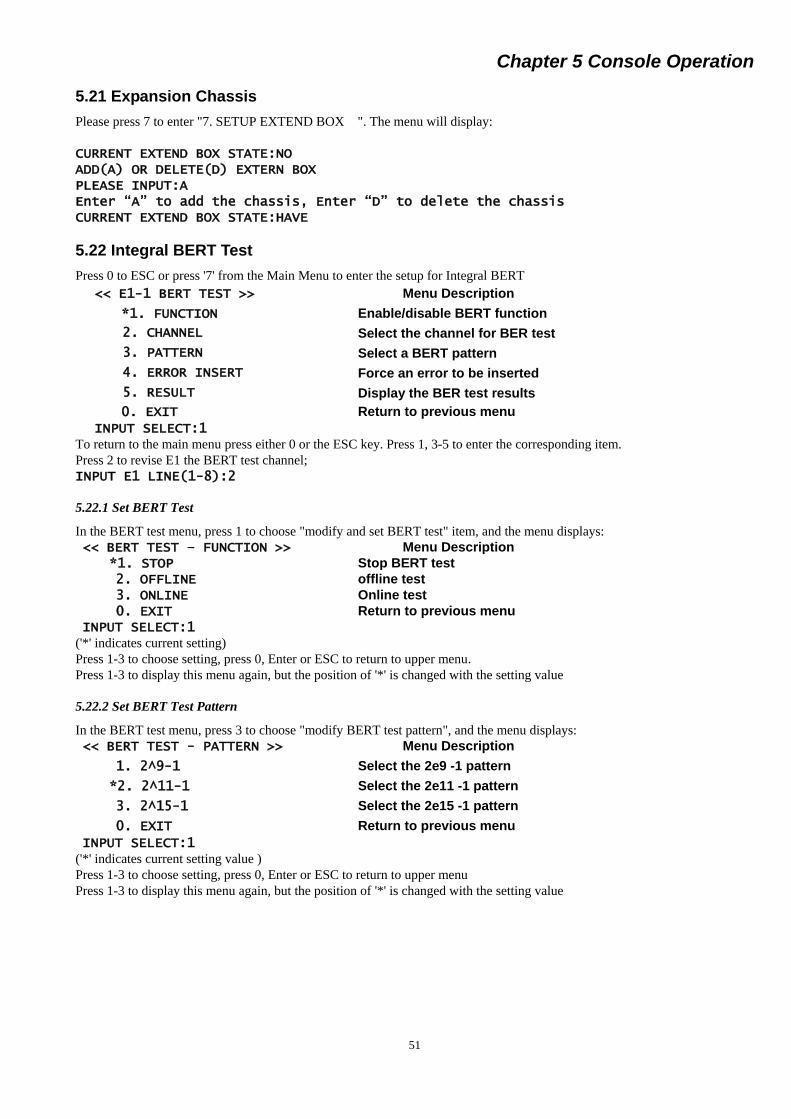
Chapter 5 Console Operation
51
5.21 Expansion Chassis
Please press 7 to enter "7. SETUP EXTEND BOX ". The menu will display:
CURRENT EXTEND BOX STATE:NO ADD(A) OR DELETE(D) EXTERN BOX PLEASE INPUT:A Enter “A” to add the chassis, Enter “D” to delete the chassis CURRENT EXTEND BOX STATE:HAVE
5.22 Integral BERT Test
Press 0 to ESC or press '7' from the Main Menu to enter the setup for Integral BERT
<< E1-1 BERT TEST >> Menu Description
*1. FUNCTION Enable/disable BERT function
2. CHANNEL Select the channel for BER test
3. PATTERN Select a BERT pattern
4. ERROR INSERT Force an error to be inserted
5. RESULT Display the BER test results
0. EXIT Return to previous menu
INPUT SELECT:1
To return to the main menu press either 0 or the ESC key. Press 1, 3-5 to enter the corresponding item.
Press 2 to revise E1 the BERT test channel;
INPUT E1 LINE(1-8):2
5.22.1 Set BERT Test
In the BERT test menu, press 1 to choose "modify and set BERT test" item, and the menu displays:
<< BERT TEST – FUNCTION >> Menu Description
*1. STOP Stop BERT test
2. OFFLINE offline test
3. ONLINE Online test
0. EXIT Return to previous menu
INPUT SELECT:1
('*' indicates current setting)
Press 1-3 to choose setting, press 0, Enter or ESC to return to upper menu.
Press 1-3 to display this menu again, but the position of '*' is changed with the setting value
5.22.2 Set BERT Test Pattern
In the BERT test menu, press 3 to choose "modify BERT test pattern", and the menu displays:
<< BERT TEST - PATTERN >> Menu Description
1. 2^9-1 Select the 2e9 -1 pattern
*2. 2^11-1 Select the 2e11 -1 pattern
3. 2^15-1 Select the 2e15 -1 pattern
0. EXIT Return to previous menu
INPUT SELECT:1
('*' indicates current setting value )
Press 1-3 to choose setting, press 0, Enter or ESC to return to upper menu
Press 1-3 to display this menu again, but the position of '*' is changed with the setting value

Chapter 5 Console Operation
52
5.22.3 Set BERT Error Code Insert
In the BERT test menu, press 4 to choose "modify BERT error code insert", and the menu displays:
<< BERT TEST - PATTERN >> Menu Description
*1. NONE
2. SINGLE Force a single bit error
3. 1E-3 Set bit error rate 1 in 1000
4. 1E-4 Set bit error rate 1 in 10,000
5. 1E-5 Set bit error rate 1 in 100,000
0. EXIT Return to previous menu
('*' indicates current setting value )
Press 1-5 to choose setting, press 0, Enter or ESC to return to upper menu
Press 1-5 to display this menu again, but the position of '*' is changed with the setting value
5.22.4 Display BERT Test Result
In BERT test menu, press 5 to display BERT test result, the menu displays:
<< BERT RESULT >> E1-2 PERFERMANCE Bipolar violations count(BPV):0 Current CRC-4 error count:0 Current errored seconds(ES):0 Current unavailable seconds(UAS):0 Current seconds(SEC):0 Long-term errored seconds(LES):0 Long-term unavailable seconds(LUAS):0 Long-term seconds(LSEC):0 OLD Current errored seconds(ES):0 OLD Current unavailable seconds(UAS):0 BIT ERROR:0 BIT ERROR RATE:0 <ESC> EXIT. <CR> CLEAR. <SPACE> REFRESH.
5.23 Exit menu, and Enter into the Monitoring Status
In the main menu, press 8 to exit menu and enter into the monitoring status.
EXIT SYSTEM,(Y/N)y YOU EXTI MENU-PROGRAM!

Chapter 6 Test and Diagnostics
53
Chapter 6 Test and Diagnostics
There are red or yellow alarm indicators on the front panel of each card, designed to indicate corresponding failure. For
example, the "Sig Loss" on E1 card means that no E1 signal is received. "Sync LOSS" indicates that E1 frame synchronization
errors have occurred.
This device is equipped with "E1 Local Loop" and "E1 To Remote Loop" functions, which can be used to facilitate the
diagnostics and tests. These loops can be set and/or cancelled via programming (console intervention).
6.1 E1 Local Loop
Figure 6.1: Local Loop
Near the external side of E1 interface, the RX interface is disconnected from external E1 line (see figure 6-1), then looped back
from TX. This aims to test the device at the user side. Connect a bit error rate tester (such as CTC Union's HCT-6000 BERT)
to any user data port to check error rate.
6.2 E1 To Remote Loop
Figure 6.2: To Remote Loop
Near the external side of E1, the TX and RX are connected to form a 'To Remote Loop' (see figure 6-2), which is used to test
the line and the device at the remote side. Connect a bit error rate tester (such as CTC Union's HCT-6000 BERT) to any user
data port of the remote side device, and check for bit errors.
Figure 6.3: end-to-end bi-directional test
Connect BERT equipment to corresponding user ports of devices at both sides, perform error code testing, and check the data
transmission quality for devices and relevant branches. Please see figure 6.3.
TX
RX
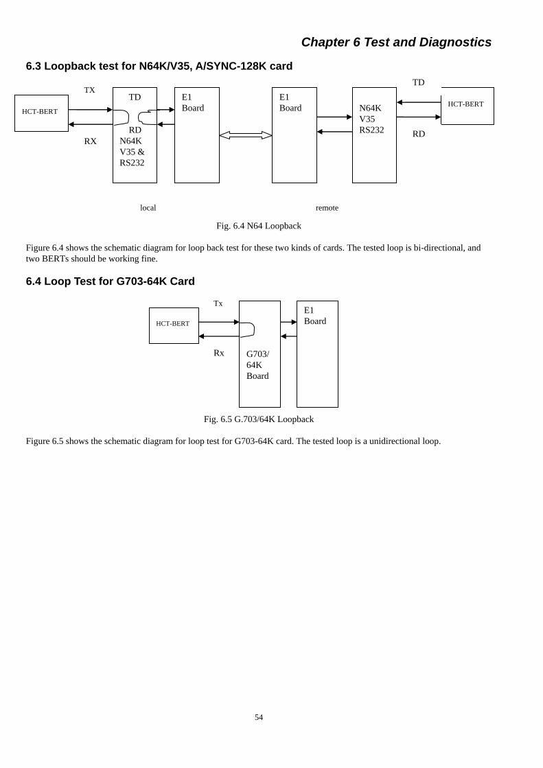
Chapter 6 Test and Diagnostics
54
6.3 Loopback test for N64K/V35, A/SYNC-128K card
Fig. 6.4 N64 Loopback
Figure 6.4 shows the schematic diagram for loop back test for these two kinds of cards. The tested loop is bi-directional, and
two BERTs should be working fine.
6.4 Loop Test for G703-64K Card
Fig. 6.5 G.703/64K Loopback
Figure 6.5 shows the schematic diagram for loop test for G703-64K card. The tested loop is a unidirectional loop.
TX
HCT-BERT
TD
RD
N64K
V35 &
RS232
RX
E1
Board
E1
Board
N64K
V35
RS232
HCT-BERT
TD
RD
local remote
Tx
HCT-BERT
G703/
64K
Board
Rx
E1
Board
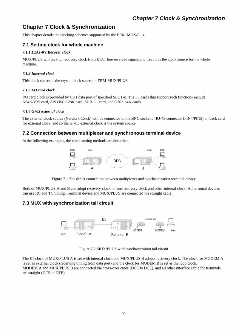
Chapter 7 Clock & Synchronization
55
CPU
Sys Alarm
AlarmI/O
Norm al
E1
T D
RD
Alarm
Loss
LossSig
Sync
Err
On Line
E1
T D
RD
Alarm
Loss
LossSig
Sync
Err
On Line
N¡Á 64K
Alarm
RD1
T D2
RD2
T D1
N¡Á 64K
Alarm
RD1
T D2
RD2
T D1
64K/
128K
Alarm
RD3
RD2
T D1
RD1
T D2
T D3
64K/
128K
Alarm
RD3
RD2
T D1
RD1
T D2
T D3
64K/
128K
Alarm
RD3
RD2
T D1
RD1
T D2
T D3
X.50
Alarm
LossSync
T D1
RD1
T D2
RD2
RD3
T D3
T D4
RD4
T D5
RD5
X.50
Alarm
LossSync
T D1
RD1
T D2
RD2
RD3
T D3
T D4
RD4
T D5
RD5
Sync
N¡Á 64K
Alarm
RD1
T D2
RD2
T D1
ASYNC
Alarm
T D2
RD2
T D1
RD1
T D3
RD3
T D4
RD4
ASYNC
Alarm
T D2
RD2
T D1
RD1
T D3
RD3
T D4
RD4
POWER
ON
POWER
ON
unionunion
ERM-MUXERM-MUX CPU
Sys Alarm
AlarmI/O
Norm al
E1
T D
RD
Alarm
Loss
LossSig
Sync
Err
On Line
E1
T D
RD
Alarm
Loss
LossSig
Sync
Err
On Line
N¡Á 64K
Alarm
RD1
T D2
RD2
T D1
N¡Á 64K
Alarm
RD1
T D2
RD2
T D1
64K/
128K
Alarm
RD3
RD2
T D1
RD1
T D2
T D3
64K/
128K
Alarm
RD3
RD2
T D1
RD1
T D2
T D3
64K/
128K
Alarm
RD3
RD2
T D1
RD1
T D2
T D3
X.50
Alarm
LossSync
T D1
RD1
T D2
RD2
RD3
T D3
T D4
RD4
T D5
RD5
X.50
Alarm
LossSync
T D1
RD1
T D2
RD2
RD3
T D3
T D4
RD4
T D5
RD5
Sync
N¡Á 64K
Alarm
RD1
T D2
RD2
T D1
ASYNC
Alarm
T D2
RD2
T D1
RD1
T D3
RD3
T D4
RD4
ASYNC
Alarm
T D2
RD2
T D1
RD1
T D3
RD3
T D4
RD4
POWER
ON
POWER
ON
unionunion
ERM-MUXERM-MUX
DCEDTE DTEDCE
A B
DDN
Chapter 7 Clock & Synchronization
This chapter details the clocking schemes supported by the ERM-MUX/Plus.
7.1 Setting clock for whole machine
7.1.1 E1A1-8's Recover clock
MUX/PLUS will pick up recovery clock from E1A1 line received signal, and treat it as the clock source for the whole
machine.
7.1.2 Internal clock
This clock source is the crystal clock source in ERM-MUX/PLUS.
7.1.3 I/O card clock
I/O card clock is provided by CH1 data port of specified SLOT-n. The IO cards that support such functions include:
N64K/V35 card, A/SYNC-128K card, SUB-E1 card, and G703-64K cards.
7.1.4 G703 external clock
The external clock source (Network Clock) will be connected to the BNC socket or RJ-45 connector (PIN4/PIN5) on back card
for external clock, and so the G.703 external clock is the system source.
7.2 Connection between multiplexer and synchronous terminal device
In the following examples, the clock setting methods are described.
Figure 7.1 The direct connection between multiplexer and synchronization terminal device
Both of MUX/PLUS A and B can adopt recovery clock, or one recovery clock and other internal clock. All terminal devices
can use RC and TC timing. Terminal device and MUX/PLUS are connected via straight cable.
7.3 MUX with synchronization tail circuit
Figure 7.2 MUX/PLUS with synchronization tail circuit
The E1 clock of MUX/PLUS A is set with internal clock and MUX/PLUS B adopts recovery clock. The clock for MODEM A
is set as external clock (receiving timing from data port) and the clock for MODEM B is set as the loop clock.
MODEM A and MUX/PLUS B are connected via cross-over cable (DCE to DCE), and all other interface cable for terminals
are straight (DCE to DTE).
CPU
Sys Alarm
AlarmI/O
Normal
E1
TD
RD
Alarm
Loss
LossSig
Sync
Err
On Line
E1
TD
RD
Alarm
Loss
LossSig
Sync
Err
On Line
N¡Á 64K
Alarm
RD1
TD2
RD2
TD1
N¡Á 64K
Alarm
RD1
TD2
RD2
TD1
64K/
128K
Alarm
RD3
RD2
TD1
RD1
TD2
TD3
64K/
128K
Alarm
RD3
RD2
TD1
RD1
TD2
TD3
64K/
128K
Alarm
RD3
RD2
TD1
RD1
TD2
TD3
X.50
Alarm
LossSync
TD1
RD1
TD2
RD2
RD3
TD3
TD4
RD4
TD5
RD5
X.50
Alarm
LossSync
TD1
RD1
TD2
RD2
RD3
TD3
TD4
RD4
TD5
RD5
Sync
N¡Á 64K
Alarm
RD1
TD2
RD2
TD1
ASYNC
Alarm
TD2
RD2
TD1
RD1
TD3
RD3
TD4
RD4
ASYNC
Alarm
TD2
RD2
TD1
RD1
TD3
RD3
TD4
RD4
POWERON
POWERON
unionunion
ERM-MUXERM-MUX
MODEM MODEM
ÖÖÖÖ
ÖÖÖÖÖÖÖ·
BACPU
Sys Alarm
AlarmI/O
Normal
E1
TD
RD
Alarm
Loss
LossSig
Sync
Err
On Line
E1
TD
RD
Alarm
Loss
LossSig
Sync
Err
On Line
N¡Á 64K
Alarm
RD1
TD2
RD2
TD1
N¡Á 64K
Alarm
RD1
TD2
RD2
TD1
64K/
128K
Alarm
RD3
RD2
TD1
RD1
TD2
TD3
64K/
128K
Alarm
RD3
RD2
TD1
RD1
TD2
TD3
64K/
128K
Alarm
RD3
RD2
TD1
RD1
TD2
TD3
X.50
Alarm
LossSync
TD1
RD1
TD2
RD2
RD3
TD3
TD4
RD4
TD5
RD5
X.50
Alarm
LossSync
TD1
RD1
TD2
RD2
RD3
TD3
TD4
RD4
TD5
RD5
Sync
N¡Á 64K
Alarm
RD1
TD2
RD2
TD1
ASYNC
Alarm
TD2
RD2
TD1
RD1
TD3
RD3
TD4
RD4
ASYNC
Alarm
TD2
RD2
TD1
RD1
TD3
RD3
TD4
RD4
POWERON
POWERON
unionunion
ERM-MUXERM-MUX
E1ÖÖÖ·
Ö× ÖÖ
ÖÖÖÖ
Local -A Remote -B DTE
DTE
E1 Leased line

Chapter 8 Application Notes
56
Chapter 8 Application Notes
8.1 Connection between MUX and public network devices
For this type of connection, various businesses can be connected to remote places via ERM-MUX/PLUS cross connection, and
many kinds of media can be used, such as DDN network, PDH, SDH, PCM, digital microwave, and so on. The
ERM-MUX/PLUS can also be used for local connections.
Fig. 8.1 Point to Point Media
8.2 Connection with program controlled exchanger
One E1 channel is used for the connection of program controlled exchanger (PBX), and other E1s are used for connecting with
public networks.
Fig. 8.2 Connecting public networks and PBX
8.3 Data connection among multiple points
In the figure 8.3, user data No.1 to No.6 can be in one time-slot or a group of time-slots. The network in figure 8.3 shows: User
data 1 is transmitted from Site A to B. user data 2 transmitted from Site A to Site C. user data 3 transmitted from Site A to Site
D. user data 4 transmitted from Site B to Site C. user data 5 transmitted from Site B to Site D. user data 6 transmitted from Site
C to Site D. You can make up the required data transmission system flexibly by using E1 channels. Additionally, the E1 clock
at Site A is set for internal clock, while the main clocks for Site B/C/D should be set for recovery clock.
Fig. 8.3 Drop and Insert Method
8.4 The extension and expansion of Data Distribution Network
Use E1 card connections to converge users from Site B/C/D into one E1 channel.
Connect them to DDN in centralized way, please refer to figure 8.4.
Fig 8.4 Point to Multi-point
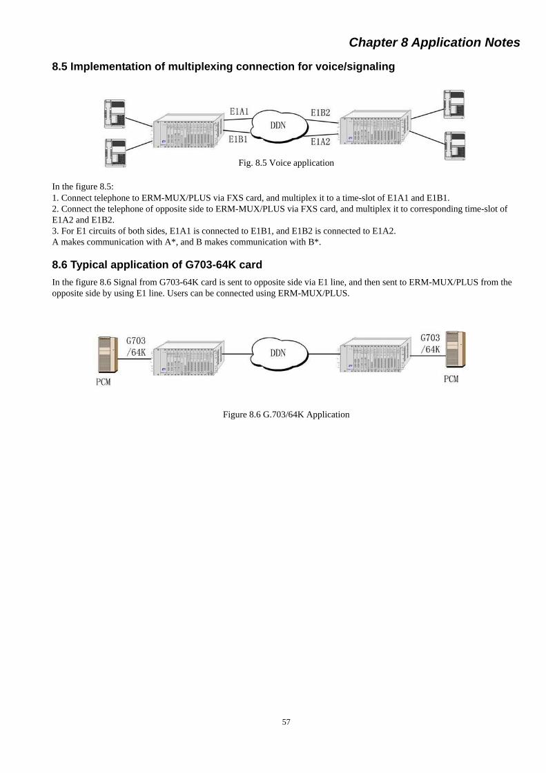
Chapter 8 Application Notes
57
8.5 Implementation of multiplexing connection for voice/signaling
Fig. 8.5 Voice application
In the figure 8.5:
1. Connect telephone to ERM-MUX/PLUS via FXS card, and multiplex it to a time-slot of E1A1 and E1B1.
2. Connect the telephone of opposite side to ERM-MUX/PLUS via FXS card, and multiplex it to corresponding time-slot of
E1A2 and E1B2.
3. For E1 circuits of both sides, E1A1 is connected to E1B1, and E1B2 is connected to E1A2.
A makes communication with A*, and B makes communication with B*.
8.6 Typical application of G703-64K card
In the figure 8.6 Signal from G703-64K card is sent to opposite side via E1 line, and then sent to ERM-MUX/PLUS from the
opposite side by using E1 line. Users can be connected using ERM-MUX/PLUS.
Figure 8.6 G.703/64K Application

Chapter 8 Application Notes
58
This page was left blank intentionally

Revision History
Date Version Description
2014/4/23 4.3 Change cover and last page image
Add a note in page 42