Embed Size (px)
Citation preview

ERTEC 200P PN IO
Evaluation Kit V4.0 User Interface Description
___________________
___________________
___________________
___________________
___________________
SIMATIC
PROFINET User Interface Description Evaluation Kit ERTEC 200P PN IO V4.0 Programming and Operating Manual
02/2013 A5E03855366-01
Preface
Introduction 1
Overview of PROFINET IO device software
2
Software creation for PROFINET IO devices
3
Interface Description 4
Appendix A

Siemens AG Industry Sector Postfach 48 48 90026 NÜRNBERG GERMANY
A5E03855366-01 Ⓟ 05/2013 Technical data subject to change
Copyright © Siemens AG 2013. All rights reserved
Legal information Warning notice system
This manual contains notices you have to observe in order to ensure your personal safety, as well as to prevent damage to property. The notices referring to your personal safety are highlighted in the manual by a safety alert symbol, notices referring only to property damage have no safety alert symbol. These notices shown below are graded according to the degree of danger.
DANGER indicates that death or severe personal injury will result if proper precautions are not taken.
WARNING indicates that death or severe personal injury may result if proper precautions are not taken.
CAUTION indicates that minor personal injury can result if proper precautions are not taken.
NOTICE indicates that property damage can result if proper precautions are not taken.
If more than one degree of danger is present, the warning notice representing the highest degree of danger will be used. A notice warning of injury to persons with a safety alert symbol may also include a warning relating to property damage.
Qualified Personnel The product/system described in this documentation may be operated only by personnel qualified for the specific task in accordance with the relevant documentation, in particular its warning notices and safety instructions. Qualified personnel are those who, based on their training and experience, are capable of identifying risks and avoiding potential hazards when working with these products/systems.
Proper use of Siemens products Note the following:
WARNING Siemens products may only be used for the applications described in the catalog and in the relevant technical documentation. If products and components from other manufacturers are used, these must be recommended or approved by Siemens. Proper transport, storage, installation, assembly, commissioning, operation and maintenance are required to ensure that the products operate safely and without any problems. The permissible ambient conditions must be complied with. The information in the relevant documentation must be observed.
Trademarks All names identified by ® are registered trademarks of Siemens AG. The remaining trademarks in this publication may be trademarks whose use by third parties for their own purposes could violate the rights of the owner.
Disclaimer of Liability We have reviewed the contents of this publication to ensure consistency with the hardware and software described. Since variance cannot be precluded entirely, we cannot guarantee full consistency. However, the information in this publication is reviewed regularly and any necessary corrections are included in subsequent editions.

ERTEC 200P PN IO Evaluation Kit V4.0 User Interface Description Programming and Operating Manual, 02/2013, A5E03855366-01 3
Preface
Preface
Purpose of the manual This user documentation describes the software functionality of the evaluation kit for a PROFINET IO device:
● Introduction
● Detailed description of the individual software functions
● Example for the user
Target group for the manual This manual is intended for software and application developers who want to use the evaluation kit for new products on various real-time platforms. Developers receive a CD with the complete source code of the IO stack, the documentation, an application example and a sample platform porting.
This manual applies to ERTEC 200P-based platforms.
Structure of the manual This manual describes the PROFINET IO device evaluation kit. It is structured as follows:
● Section 1: Introduction
● Section 2: Overview of PROFINET IO device software
● Section 3: Software Creation for PROFINET IO Devices
● Section 4: Interface Description
● Appendix: Abbreviations / Glossary of terms, References
This manual includes the description of the PROFINET IO stack for the supported evaluation kit at the time of release. We reserve the right to update the user documentation in light of new product releases.

Preface
ERTEC 200P PN IO Evaluation Kit V4.0 User Interface Description 4 Programming and Operating Manual, 02/2013, A5E03855366-01
Guide The manual contains various navigation aids that allow you to find specific information more quickly:
● A complete table of contents as well as a list of all figures and tables are provided at the beginning of the manual.
● In the appendix you will find list of abbreviations and a glossary, which define important technical terms used in this manual.
● References to other documents are indicated by the document reference number enclosed in slashes ("/No./"). The complete title of the document can be obtained from the list of references in the appendix of the manual.
Conventions The terms "ThreadId" and "TaskId" are used synonymously in this manual.
Please observe notes labeled as follows:
Note
A note contains important information about the described product, about handling the product or about a specific section of the documentation that requires special consideration.
Additional support If you have questions regarding the described evaluation kit that are not addressed in the documentation, please contact your local representative at the Siemens office nearest you.
Please send questions, comments and suggestions regarding this manual in writing to the specified e-mail address.
In addition, you will find general information, current product information, FAQs and downloads that can be useful on the Internet (http://www.siemens.com/comdec).
Technical contact for Germany / worldwide Siemens AG ComDeC (http://www.siemens.com/comdec)
Phone: +49 911 750 2080 Phone: +49 911 750 4384 Phone: +49 911 750 2078 Fax: +49 911 750 2100 E-mail: (mailto:[email protected])
Office address: Würzburger Str. 121 90766 Fürth, Germany
Postal address: P.O. Box 2355 90713 Fürth, Germany

Preface
ERTEC 200P PN IO Evaluation Kit V4.0 User Interface Description Programming and Operating Manual, 02/2013, A5E03855366-01 5
Technical contact for the USA PROFI Interface Center (http://www.profiinterfacecenter.com) One Internet Plaza Johnson City, TN 37604
Phone: +1 (423) 262-2576 Fax: +1 (678) 297-7289 E-mail: (mailto:[email protected])

Preface
ERTEC 200P PN IO Evaluation Kit V4.0 User Interface Description 6 Programming and Operating Manual, 02/2013, A5E03855366-01

ERTEC 200P PN IO Evaluation Kit V4.0 User Interface Description Programming and Operating Manual, 02/2013, A5E03855366-01 7
Table of contents
Preface ................................................................................................................................................... 3
1 Introduction ........................................................................................................................................... 13
1.1 Content and target audience of this interface description............................................................ 13
1.2 Example platforms ....................................................................................................................... 14
1.3 Other information ......................................................................................................................... 14
2 Overview of PROFINET IO device software .......................................................................................... 15
2.1 Software architecture ................................................................................................................... 15 2.1.1 Software architecture ................................................................................................................... 16 2.1.1.1 ERTEC 200P ................................................................................................................................ 16
2.2 Components of the PROFINET IO stack ..................................................................................... 17 2.2.1 EDDP (Ethernet Device Driver for ERTEC 200P) ....................................................................... 17 2.2.2 ACP (Acyclic Communication Protocol) ....................................................................................... 17 2.2.3 CM (Context Manager) ................................................................................................................ 18 2.2.4 CLRPC (Connectionless Remote Procedure Call) ...................................................................... 18 2.2.5 DCP (Dynamic Configuration Protocol) ....................................................................................... 18 2.2.6 GSY (Generic Sync Module) ........................................................................................................ 18 2.2.7 LLDP (Link Layer Discovery Protocol) ......................................................................................... 18 2.2.8 MRP (Media Redundancy Protocol) ............................................................................................ 19 2.2.9 OHA (Object Handler) .................................................................................................................. 19 2.2.10 POF (Polymeric optical fiber) ....................................................................................................... 19 2.2.11 SOCK (socket interface) .............................................................................................................. 19 2.2.12 TCP/IP stack ................................................................................................................................ 19 2.2.13 System adaptation (SYS, LSAS) ................................................................................................. 19 2.2.14 OS Abstraction Layer (OS Adapt) ................................................................................................ 20 2.2.15 PNDV ........................................................................................................................................... 20 2.2.16 PNPB ........................................................................................................................................... 20
2.3 Additional software components .................................................................................................. 20 2.3.1 Operating system ......................................................................................................................... 20 2.3.2 Board Support Package (BSP) .................................................................................................... 20
2.4 Application examples ................................................................................................................... 21 2.4.1 General structure of the application examples ............................................................................ 22 2.4.2 Isochronous applications with IRT, T_Input and T_Output evaluation......................................... 24 2.4.3 App1: SI-based example for RT and IRT ..................................................................................... 25 2.4.4 App2: DBAI-based example for RT and IRT ................................................................................ 26

Table of contents
ERTEC 200P PN IO Evaluation Kit V4.0 User Interface Description 8 Programming and Operating Manual, 02/2013, A5E03855366-01
3 Software creation for PROFINET IO devices ......................................................................................... 27
3.1 Directory structure of the PROFINET IO source code ................................................................ 27
3.2 Files for the application examples ............................................................................................... 30 3.2.1 Files for App1_STANDARD ........................................................................................................ 30 3.2.2 Files for App2_DBAI .................................................................................................................... 30 3.2.3 Files for App3_IsoApp ................................................................................................................. 30 3.2.4 Files for App_common ................................................................................................................ 31 3.2.5 Application interface .................................................................................................................... 32 3.2.6 Operating system interface modules to be adapted ................................................................... 32 3.2.7 Socket interface modules to be adapted ..................................................................................... 32 3.2.8 Modules of the BSP interface...................................................................................................... 33 3.2.9 Storage of retentive data ............................................................................................................. 33 3.2.10 Other files for system adaptation ................................................................................................ 33
3.3 Important constraints for integrating an application .................................................................... 34
3.4 Porting the PROFINET IO software to another platform ............................................................. 35 3.4.1 Porting to customer hardware with the same microcontroller and the same OS ........................ 35 3.4.2 Use of other compilers/linkers ..................................................................................................... 36 3.4.2.1 Tool chain selection .................................................................................................................... 36 3.4.2.2 Big Endian or Little Endian .......................................................................................................... 36 3.4.2.3 Data alignment requirements ...................................................................................................... 36 3.4.2.4 Data processing capacity ............................................................................................................ 37 3.4.2.5 Memory management ................................................................................................................. 37 3.4.3 Use of other operating systems .................................................................................................. 37
3.5 Typical sequence of an IO device user program ........................................................................ 38 3.5.1 Initialization phase ....................................................................................................................... 39 3.5.2 Productive operation ................................................................................................................... 41 3.5.3 Completion phase ....................................................................................................................... 44
3.6 Basic data traffic in the IO device user interface......................................................................... 44
3.7 Cyclic IO data traffic of the IO device user interface ................................................................... 45 3.7.1 Cyclic writing with status ............................................................................................................. 46 3.7.2 Cyclic reading with status ............................................................................................................ 47 3.7.3 Cyclic data communication using the optional DBA interface ..................................................... 47
3.8 IO data communication for IRT class 3 (ERTEC-based platforms) ............................................ 48
3.9 Managing diagnostic data ........................................................................................................... 48 3.9.1 Channel diagnostic data .............................................................................................................. 48 3.9.2 Manufacturer-specified diagnostic data ...................................................................................... 50
3.10 Details when inserting and removing modules during productive operation .............................. 51 3.10.1 Special features with "Return of submodule" .............................................................................. 52
3.11 Callback mechanism ................................................................................................................... 52

Table of contents
ERTEC 200P PN IO Evaluation Kit V4.0 User Interface Description Programming and Operating Manual, 02/2013, A5E03855366-01 9
4 Interface Description ............................................................................................................................. 55
4.1 Upper layer interface functions for the application ....................................................................... 55 4.1.1 Functions for system startup ........................................................................................................ 56 4.1.1.1 PNIO_init ...................................................................................................................................... 56 4.1.1.2 PNIO_setup .................................................................................................................................. 56 4.1.1.3 PNIO_device_open ...................................................................................................................... 57 4.1.1.4 PNIO_async_appl_rdy .................................................................................................................. 58 4.1.1.5 PNIO_device_close ...................................................................................................................... 58 4.1.1.6 PNIO_CP_register_cbf ................................................................................................................. 59 4.1.2 Setting the device name and IP suite .......................................................................................... 59 4.1.2.1 PNIO_cbf_save_station_name ..................................................................................................... 60 4.1.2.2 PNIO_cbf_save_ip_addr ............................................................................................................... 60 4.1.2.3 PNIO_cbf_start_led_blink ............................................................................................................. 60 4.1.2.4 PNIO_cbf_stop_led_blink ............................................................................................................. 61 4.1.2.5 PNIO_cbf_reset_factory_settings ................................................................................................. 61 4.1.3 Storage of retentive data (REMA) ................................................................................................ 61 4.1.3.1 PNIO_cbf_store_rema_mem ........................................................................................................ 62 4.1.3.2 PNIO_cbf_restore_rema_mem ..................................................................................................... 62 4.1.4 IO device configuration ................................................................................................................ 63 4.1.4.1 PNIO_sub_plug ............................................................................................................................ 63 4.1.4.2 PNIO_sub_plug_list ...................................................................................................................... 64 4.1.4.3 PNIO_sub_pull ............................................................................................................................. 64 4.1.5 Storing diagnostic data in the subslot .......................................................................................... 65 4.1.5.1 PNIO_diag_channel_add ............................................................................................................. 65 4.1.5.2 PNIO_diag_channel_remove ....................................................................................................... 65 4.1.5.3 PNIO_ext_diag_channel_add ....................................................................................................... 66 4.1.5.4 PNIO_ext_diag_channel_remove ................................................................................................. 67 4.1.5.5 PNIO_diag_generic_add .............................................................................................................. 68 4.1.5.6 PNIO_diag_generic_remove ........................................................................................................ 68 4.1.6 Sending and receiving alarms ...................................................................................................... 69 4.1.6.1 PNIO_process_alarm_send ......................................................................................................... 69 4.1.6.2 PNIO_upload_retrieval_alarm_send............................................................................................. 70 4.1.6.3 PNIO_ret_of_sub_alarm_send ..................................................................................................... 70 4.1.6.4 PNIO_cbf_dev_alarm_ind() .......................................................................................................... 71 4.1.7 Acknowledgement of asynchronous functions ............................................................................. 71 4.1.7.1 PNIO_cbf_async_req_done .......................................................................................................... 71 4.1.8 Reading and writing records ........................................................................................................ 72 4.1.8.1 PNIO_cbf_rec_read ...................................................................................................................... 74 4.1.8.2 PNIO_cbf_rec_write ..................................................................................................................... 75 4.1.8.3 PNIO_rec_set_rsp_async ............................................................................................................. 75 4.1.8.4 PNIO_rec_read_rsp ...................................................................................................................... 76 4.1.8.5 PNIO_rec_write_rsp ..................................................................................................................... 76 4.1.9 Cyclic data exchange by means of the standard callback interface (SCI) .................................. 77 4.1.9.1 PNIO_initiate_data_read, PNIO_initiate_data_write ..................................................................... 77 4.1.9.2 PNIO_cbf_data_write, PNIO_cbf_data_read ................................................................................ 78 4.1.10 Cyclic data exchange by means of the optional DBA interface ................................................... 79 4.1.10.1 Cyclic data exchange by means of the optional DBA interface ................................................... 79 4.1.10.2 PNIO_dbai_enter .......................................................................................................................... 80 4.1.10.3 PNIO_dbai_exit ............................................................................................................................ 80 4.1.10.4 PNIO_dbai_buf_lock ..................................................................................................................... 81 4.1.10.5 PNIO_dbai_buf_unlock ................................................................................................................. 81 4.1.11 Receiving events and alarms ....................................................................................................... 82

Table of contents
ERTEC 200P PN IO Evaluation Kit V4.0 User Interface Description 10 Programming and Operating Manual, 02/2013, A5E03855366-01
4.1.11.1 PNIO_cbf_ar_connect_ind ........................................................................................................... 82 4.1.11.2 PNIO_cbf_ar_ownership_ind ....................................................................................................... 83 4.1.11.3 PNIO_cbf_ar_indata_ind .............................................................................................................. 83 4.1.11.4 PNIO_cbf_ar_disconn_ind ........................................................................................................... 84 4.1.11.5 PNIO_cbf_param_end_ind .......................................................................................................... 84 4.1.12 Control functions ......................................................................................................................... 85 4.1.12.1 PNIO_set_dev_state .................................................................................................................... 85 4.1.13 Hardware comparators for isochronous mode ............................................................................ 86 4.1.13.1 Hardware comparators for isochronous mode ............................................................................ 86 4.1.13.2 PNIO_IsoActivateIsrObj .............................................................................................................. 87 4.1.13.3 PNIO_IsoActivateGpioObj ........................................................................................................... 87 4.1.13.4 PNIO_IsoActivateTransEndObj ................................................................................................... 88 4.1.13.5 PNIO_IsoFreeObj ........................................................................................................................ 88 4.1.14 Error handling .............................................................................................................................. 89 4.1.14.1 PNIO_get_last_error .................................................................................................................... 89 4.1.14.2 PNIO_Log .................................................................................................................................... 90 4.1.14.3 PNIO_set_iops ............................................................................................................................ 91 4.1.15 Other functions ............................................................................................................................ 91 4.1.15.1 PNIO_printf .................................................................................................................................. 91 4.1.15.2 PNIO_TrcPrintf ............................................................................................................................ 91 4.1.15.3 PNIO_get_version ....................................................................................................................... 92
4.2 Lower layer interface functions for the Board Support Package................................................. 92 4.2.1 BSP functions for all platforms .................................................................................................... 92 4.2.1.1 Bsp_Init ........................................................................................................................................ 92 4.2.1.2 Bsp_GetMacAddr ........................................................................................................................ 92 4.2.1.3 Bsp_GetPortMacAddr ................................................................................................................. 92 4.2.1.4 Bsp_EbSetLed (implementation optional) ................................................................................... 93 4.2.2 Storage of non-volatile data ........................................................................................................ 93 4.2.2.1 Bsp_nv_data_clear ...................................................................................................................... 93 4.2.2.2 Bsp_nv_data_store ...................................................................................................................... 94 4.2.2.3 Bsp_nv_data_restore ................................................................................................................... 94 4.2.2.4 Bsp_nv_data_memfree ................................................................................................................ 94 4.2.3 Adaptation of the ERTEC switch interrupts (ERTEC platforms only) ......................................... 95 4.2.4 GPIO connection (only for ERTEC platforms) ............................................................................ 95 4.2.4.1 Bsp_ReadGPIOin_0_to_31 (implementation optional) ................................................................ 95 4.2.4.2 Bsp_SetGPIOout_0_to_31 (implementation optional) ................................................................. 95 4.2.4.3 Bsp_ClearGPIOout_0_to_31 (implementation optional) ............................................................. 96
4.3 Interface to the operating system ................................................................................................ 96 4.3.1 Interface to the operating system ................................................................................................ 96 4.3.2 Managing resources .................................................................................................................... 96 4.3.3 Description of the OS functions to be ported .............................................................................. 97 4.3.3.1 OsInit() ......................................................................................................................................... 97 4.3.3.2 OsAllocFX() ................................................................................................................................. 97 4.3.3.3 OsFreeX().................................................................................................................................... 97 4.3.3.4 OsAllocTimer() ............................................................................................................................ 98 4.3.3.5 OsStartTimer() ............................................................................................................................ 98 4.3.3.6 OsStopTimer() ............................................................................................................................. 99 4.3.3.7 OsFreeTimer() ............................................................................................................................. 99 4.3.3.8 OsEnterX() .................................................................................................................................. 99 4.3.3.9 OsExitX ....................................................................................................................................... 99 4.3.3.10 OsEnterShort ............................................................................................................................ 100

Table of contents
ERTEC 200P PN IO Evaluation Kit V4.0 User Interface Description Programming and Operating Manual, 02/2013, A5E03855366-01 11
4.3.3.11 OsExitShort ................................................................................................................................ 100 4.3.3.12 OsAllocSemB ............................................................................................................................. 100 4.3.3.13 OsFreeSemB ............................................................................................................................. 100 4.3.3.14 OsTakeSemB ............................................................................................................................. 100 4.3.3.15 OsGiveSemB ............................................................................................................................. 101 4.3.3.16 OsSetThreadPrio ....................................................................................................................... 101 4.3.3.17 OsCreateThread ........................................................................................................................ 101 4.3.3.18 OsStartThread............................................................................................................................ 102 4.3.3.19 OsWaitOnEnable() ..................................................................................................................... 102 4.3.3.20 OsGetThreadId() ........................................................................................................................ 102 4.3.3.21 OsCreateMsgQueue() ................................................................................................................ 103 4.3.3.22 OsWait_ms() .............................................................................................................................. 103 4.3.3.23 OsGetTime_us() ......................................................................................................................... 103 4.3.3.24 OsGetUnixTime() ....................................................................................................................... 103 4.3.3.25 OsReadMessageBlocked() ........................................................................................................ 104 4.3.3.26 OsReadMessageBlockedX() ...................................................................................................... 104 4.3.3.27 OsSendMessage() ..................................................................................................................... 104 4.3.3.28 OsSendMessageX() ................................................................................................................... 105 4.3.3.29 __InterlockedDecrement() .......................................................................................................... 105 4.3.3.30 __InterlockedIncrement() ........................................................................................................... 105 4.3.3.31 OsIntDisable() ............................................................................................................................ 105 4.3.3.32 OsIntEnable() ............................................................................................................................. 106 4.3.4 Encapsulation of standard library function calls ......................................................................... 106 4.3.5 OS functions called by the application example ........................................................................ 107
4.4 Important notes and limitations .................................................................................................. 107 4.4.1 Number of IO devices ................................................................................................................ 107 4.4.2 Number of modules and submodules ........................................................................................ 107 4.4.3 Maximum amount of user data for a device ............................................................................... 107 4.4.4 Functional limitations ................................................................................................................. 108
A Appendix............................................................................................................................................. 109
A.1 Abbreviations / Glossary of terms .............................................................................................. 109
A.2 References ................................................................................................................................. 111

Table of contents
ERTEC 200P PN IO Evaluation Kit V4.0 User Interface Description 12 Programming and Operating Manual, 02/2013, A5E03855366-01
Tables
Table 2- 1 Differences between the stack layers in the various development packages ............................. 15 Table 3- 1 Structure and description of the directories ................................................................................. 27 Table 3- 2 Files for the application example ................................................................................................. 31 Table 3- 3 Header files for the application interface ...................................................................................... 32 Table 3- 4 Files for the operating system abstraction interface .................................................................... 32 Table 3- 5 Files for the socket abstraction interface ..................................................................................... 32 Table 3- 6 Files for adaptation to the board support package ...................................................................... 33 Table 3- 7 Files for the adaptation to retentive data ...................................................................................... 33 Table 3- 8 Other files for system adaptation ................................................................................................. 33 Table 3- 9 API functions to be called during the startup phase .................................................................... 39 Table 3- 10 API functions to be called for reading RT and IRT IO data .......................................................... 41 Table 3- 11 API functions to be called for writing RT and IRT IO data ........................................................... 41 Table 3- 12 API functions to be called for synchronous reading of record data ............................................. 42 Table 3- 13 API functions to be called for asynchronous reading of record data ........................................... 42 Table 3- 14 API functions to be called for synchronous writing of record data ............................................... 42 Table 3- 15 API functions to be called for asynchronous writing of record data ............................................. 43 Table 3- 16 API callback functions for establishing/terminating a connection ................................................ 43 Table 3- 17 API functions to be called for the creation of a diagnostic record ................................................ 48 Table 3- 18 API functions to be called for the activation of a created diagnostic record ................................ 49 Table 3- 19 API functions to be called for the removal of a diagnostic record ................................................ 49 Table 3- 20 API functions to be called for the creation a generic diagnostic record ....................................... 50 Table 3- 21 API functions to be called for the activation a generic diagnostic record .................................... 50 Table 3- 22 API functions to be called for the removal of a generic diagnostic record ................................... 50 Table 3- 23 Overview of the callback functions in the IO device .................................................................... 52
Figures
Figure 2-1 System environment for an ERTEC-based IO device with integrated TCP/IP stack ................... 16 Figure 2-2 Tasks of the PROFINET IO application example ........................................................................ 23 Figure 4-1 Synchronous read record handling .............................................................................................. 72 Figure 4-2 Asynchronous read record handling ............................................................................................ 73
ERTEC 200P PN IO Evaluation Kit V4.0 User Interface Description Programming and Operating Manual, 02/2013, A5E03855366-01 13
Introduction 1
PROFINET is an automation concept for implementing modular, distributed applications. PROFINET allows you to create automation solutions, which are familiar to you from PROFIBUS. PROFINET is implemented by the PROFINET standard for automation devices and by the engineering tool (STEP 7, TIA Portal). This means you have the same application view in engineering regardless of whether you are configuring PROFINET devices or PROFIBUS devices. As a result, programming of the user program is almost identical for PROFINET and PROFIBUS.
A software stack is offered for PROFINET which enables PROFINET IO devices to be created. As a result of the stack, the user does not have to create the complete communication software.
The functionality includes:
● Cyclic and acyclic data communication with one or more PROFINET IO controllers
● Send and receive diagnostic and process alarms, plug and pull alarms
● Assignment of IP addresses and device names via Ethernet
The stack is supplied in the source code and can be ported to any hardware and operating system platform. Necessary adaptations are encapsulated in defined interfaces to the hardware and operating system, thus enabling the stack to be ported as simply and cost-effectively as possible.
A good knowledge of PROFINET IO is required to implement the firmware stack.
1.1 Content and target audience of this interface description This document is intended for developers of PROFINET IO devices. It contains:
● Overview of the structure of the software stack
● Description of the PROFINET IO stack interface
● Description of the network and operating system connection of the PROFINET stack
● Description of the user example
This documentation does not include:
● Overview of PROFINET
● Description of the PROFINET protocol
● Detailed description of the PROFINET IO stack structure and processes

Introduction 1.2 Example platforms
ERTEC 200P PN IO Evaluation Kit V4.0 User Interface Description 14 Programming and Operating Manual, 02/2013, A5E03855366-01
1.2 Example platforms Only the following platform is currently supported:
● ERTEC 200P, eCos 3.0 Operating System, Evaluation Board EB 200P
1.3 Other information When porting the software to other platforms, we recommend that you not modify the central components of the PROFINET IO stack. This will make it simpler for the user to update to future versions.
The user example was tested on the respective platforms (see above).

ERTEC 200P PN IO Evaluation Kit V4.0 User Interface Description Programming and Operating Manual, 02/2013, A5E03855366-01 15
Overview of PROFINET IO device software 2 2.1 Software architecture
The following figures show the hierarchical structure of a PROFINET device in a system environment with a real-time operating system. Here we have to distinguish between the hardware platform (ERTEC or standard Ethernet controller), an external TCP/IP stack (e.g., the native TCP/IP stack of the operating system used) or the Interniche TCP/IP stack included in the ERTEC development kit. Additionally, with standard Ethernet controllers the lower layer interface of the TCP/IP stack can be set on top on the EDD or directly on the BSP. The following combinations are included in the development packages:
Table 2- 1 Differences between the stack layers in the various development packages
EB 200P, eCos platform EB 200/400, eCos platform
Standard Ethernet controller, NETOS platform
TCP/IP stack Interniche TCP/IP stack, integrated in PNIO
Interniche TCP/IP stack, integrated in PNIO
Interniche TCP/IP stack, integrated in PNIO
SNMP MIB2 agent Interniche TCP/IP stack, integrated in PNIO
Interniche TCP/IP stack, integrated in PNIO
Interniche TCP/IP stack, integrated in PNIO
Lower IP layer connection
On EDDP On EDDI On EDDI
EDD EDDP EDDI EDDS
The PROFINET IO device software consists of the following components:
● PROFINET IO protocol software (shown in light blue)
● System adaptation (shown in dark blue)
● Real-time operating system
● Board support package
● Platform-specific adaptation layer
● Device application (shown in dark gray)
All of the PROFINET IO components shown in blue are provided by SIEMENS. The light green components are generally supplied by the manufacturer of the operating system or controller. Only the dark green components must be adapted to the platform by the user; the other components can generally be used without modification. Example code is included in the PROFINET IO software stack for the adaptation of the dark green components. It is suitable for the respective example platforms.

Overview of PROFINET IO device software 2.1 Software architecture
ERTEC 200P PN IO Evaluation Kit V4.0 User Interface Description 16 Programming and Operating Manual, 02/2013, A5E03855366-01
2.1.1 Software architecture
2.1.1.1 ERTEC 200P
Red arrows Application interface Orange arrows Operating system - abstraction interface (OS Adapt) Light orange arrow Hardware - abstraction interface (BSP Adapt)
Figure 2-1 System environment for an ERTEC-based IO device with integrated TCP/IP stack
This platform has the following properties:
● Complete solution for PROFINET including Interniche IP stack
● SNMP Agent (MIB2, SNMP-MIB) contained in the stack
● Implemented for eCos platform
Overview of PROFINET IO device software 2.2 Components of the PROFINET IO stack
ERTEC 200P PN IO Evaluation Kit V4.0 User Interface Description Programming and Operating Manual, 02/2013, A5E03855366-01 17
2.2 Components of the PROFINET IO stack The following subsection provides a brief overview of the components in the PROFINET IO stack. The components of the stack can basically be broken down into the following categories:
● System-independent basic packages with a uniform interface structure These include ACP, CM, CLRPC, DCP, EDD, GSY, POF (in preparation), LLDP, MRP, OHA, TCP/IP Stack and SOCK. The basic packages merely provide a function library of sorts, which does not become an actual, executable system implementation until combined with the system integration.
● System integration (SYS, LSAS) for all included software packages This forms the interface between the individual system-independent basic packages and the operating system services, such as memory management, task management, interprocess communication, and time management. System adaptation also implements the software structure of the IO stack, which means which basic packages are executed in which tasks and by which mechanisms tasks communicate with each other.
● OS abstraction layer Forms a low-layer abstraction interface between the system adaptation and a specific operating system. As a result, when the software is ported to a different operating system, only the OS abstraction layer has to be adapted.
● Additional software packages such as PNDV and PNPB
2.2.1 EDDP (Ethernet Device Driver for ERTEC 200P) The EDDP provides mechanisms for:
● Independent sending and receiving of cyclic real-time message frames.
● Sending and receiving of acyclic real-time message frames.
● Sending and receiving of non-real-time message frames.
The EDDP has a uniform LSA interface to higher-level clients (ACP, DCP, GSY, LLDP, MRP, etc.).
2.2.2 ACP (Acyclic Communication Protocol) Processing of:
● Diagnostic alarms
● Alarms
● Return of submodule alarms
● Upload/retrieval alarms (parameter server)
The ACP generates the alarm message frames and monitors the correct functioning of the associated Ethernet protocol (alarm acknowledgments, timeout).

Overview of PROFINET IO device software 2.2 Components of the PROFINET IO stack
ERTEC 200P PN IO Evaluation Kit V4.0 User Interface Description 18 Programming and Operating Manual, 02/2013, A5E03855366-01
2.2.3 CM (Context Manager) ● Establishing and managing communication links between IO device and IO controller
– Requests for establishment of communication links are sent by remote IO controllers to the context manager using "Connectionless Remote Procedure Calls" via UDP and CLRPC.
● Management of the actual configuration (inserted modules and submodules)
● Interface to the upper layer (PNDV)
2.2.4 CLRPC (Connectionless Remote Procedure Call) ● Implementation of the connectionless RPC protocol
2.2.5 DCP (Dynamic Configuration Protocol) ● Assignment of IP addresses and device names via Ethernet
● Reading readiness information, for example:
– Which PROFINET devices are active on the network
– Which PROFINET device has the following device name
– Hello message for Fast StartUp signals readiness to establish a connection after power on
2.2.6 GSY (Generic Sync Module) ● Processing the synchronization message frames from the sync master
● Line length measurement
● Synchronization monitoring
2.2.7 LLDP (Link Layer Discovery Protocol) ● Protocol for the exchange of neighborhood information for topology discovery
● Cyclic sending of LLDP packets with the own station data (chassis ID, port ID, etc.)
● Receipt of LLDP packets from other stations and local storage
● Provides received data with the associated port ID
● Receive monitoring and notification to the user in the event of a change or loss of the LLDP data

Overview of PROFINET IO device software 2.2 Components of the PROFINET IO stack
ERTEC 200P PN IO Evaluation Kit V4.0 User Interface Description Programming and Operating Manual, 02/2013, A5E03855366-01 19
2.2.8 MRP (Media Redundancy Protocol) ● Media redundancy for PROFINET devices
● An MRP client is supported.
2.2.9 OHA (Object Handler) ● Information functions for the application
● Generation of change messages for the application
● "Application" for DCP server and LLDP
● SNMP connection (agent) via SOCK
2.2.10 POF (Polymeric optical fiber) (Coming soon, features are not included in this version)
2.2.11 SOCK (socket interface) ● Internal adaptation interface for handling UDP-based services in the PROFINET stack
2.2.12 TCP/IP stack ● Implementation of TCP and UDP functionality (PROFINET only uses UDP)
● Based on Interniche TCP/IP stack
● Sending and receiving of raw Ethernet IP message frames
● Internal adaptation interface to PROFINET stack-internal SNMP MIB agents (MIB2, LLDP MIB)
2.2.13 System adaptation (SYS, LSAS) ● Shared implementation of the system adaptation of the individual basic packages
● Routing of operating system services for memory management, task and timer handling, and interprocess communication to the OS abstraction layer
● Implementation of tasks and communication between tasks

Overview of PROFINET IO device software 2.3 Additional software components
ERTEC 200P PN IO Evaluation Kit V4.0 User Interface Description 20 Programming and Operating Manual, 02/2013, A5E03855366-01
2.2.14 OS Abstraction Layer (OS Adapt) ● Operating system abstraction interface for PNIO
● PNIO components never directly access an operating system call; rather, access is via the OS abstraction layer only.
● Maps all requirements of the system adaptation onto simple operating system services, which are implemented almost 1:1 in a service call for most real-time operating systems.
– This facilitates simple adaptability to another real-time operating system
2.2.15 PNDV ● Implementation of generic parts of the device application
● Starting and initializing the PROFINET stack
● Generation of tasks and communication channels within the PROFINET stack
● Communicates with higher-level layers via a stack-internal memory interface
2.2.16 PNPB ● Implementation of PROFINET IO device user interface for the customer application
● Communicates with the PNDV via an internal interface
2.3 Additional software components
2.3.1 Operating system The real-time operating system is not part of the PROFINET IO software stack. It is generally procured from a third-party vendor. The supplied user example is customized for each example platform; see section Example platforms (Page 14).
2.3.2 Board Support Package (BSP) The board support package (BSP) encapsulates the hardware-specific operating system calls for a specified platform. A platform-specific BSP is generally provided by the manufacturer of the operating system. For the EB 200P Evaluation Board, a BSP for the employed operating system is included in the Evaluation Kit scope of delivery. This can be used as an example template for adapting a BSP to a customer-specific platform.

Overview of PROFINET IO device software 2.4 Application examples
ERTEC 200P PN IO Evaluation Kit V4.0 User Interface Description Programming and Operating Manual, 02/2013, A5E03855366-01 21
2.4 Application examples Various application examples have been integrated into the evaluation kit to optimally adapt PROFINET to a wide variety of requirements. They show examples of how to use the API and can be used as templates for your own implementation.
The following mechanisms have been implemented in the PROFINET stack for IO data access:
● Standard Interface (SI): universally applicable, for simple handling of RT and IRT.
● Direct Buffer Access Interface (DBAI): offers performance advantages when there is a large number of modules/submodules and can be used for RT and IRT.
With respect to IO data access, the application examples included in the development kit are each based on one of the interfaces listed above. Access to acyclic services like PROFINET stack startup, connection establishment, reading and writing records or alarm handling is identical for the interfaces listed above. Additional information on the interfaces and acyclic services is available in section Important constraints for integrating an application (Page 34).
When creating your own application, we recommend that you start with the supplied application examples. The following table provides points of reference for selecting the best suited application example.
Application Description Properties App1_Standard Universal example, based on the
standard interface (SI). • Recommended template for most applications • Simple and fast implementation • Can be used for RT and IRT • Independently manages multiple ARs • Module/submodule-oriented view from the application onto
the IO data, which means it need not know about the ARs or IOCRs.
• Data consistency is automatically guaranteed by means of buffered access
App2_DBAI Direct Buffer Access Interface • Performance advantages relative to SI (only) if a large number of modules/submodules are used
• Can be used for RT and IRT • IOCR-oriented view onto the IO data, which means the
application must manage the ARs and IOCRs itself. • Data consistency is automatically guaranteed by means of
buffered access
App3_IsoApp Isochronous application for IRT • Structure similar to "App1_Standard", which means the same access method for IO data and acyclic services
• Employs IO modules that require IRT, which means it can only be used in IRT mode
• Manages ISO record index 0x8030 for specifying T_Input, T_Output and cycle time
• Triggers interrupts or hardware signals GPIO 5, 7 at the time T_Input and T_Output

Overview of PROFINET IO device software 2.4 Application examples
ERTEC 200P PN IO Evaluation Kit V4.0 User Interface Description 22 Programming and Operating Manual, 02/2013, A5E03855366-01
2.4.1 General structure of the application examples The general software architecture of the PNIO stack has already been introduced in section Software architecture (Page 15). The structure of the application examples is largely identical.
The application is mainly comprised of the following components:
● Main task (entry function "mainAppl()") This task starts by initializing the PROFINET stack. Then the task waits in an endless loop for keypad input via the function "OsGetChar()". Typical commands can thus be executed from a terminal connected to the RS232, for example, sending alarms, pulling/plugging modules during operation, etc.
● IO_Cycle task This task cyclically executes an IO data exchange between the PROFINET stack and the application. The cyclic trigger here is either an event derived from the ERTEC (the so-called "TRANS_END" event = point in time at which the current output data in the device is made available) or a fixed wait time. The "TRANS_END" event signals the end of the data communication phase for IRT, which means all data of provider IOCRs have been sent and all data of consumer IOCRs have been received. But it can also be used for RT, in which case it signals that all local provider IOCRs were sent. If a fixed waiting period is used as trigger instead, there is no synchronization between application cycle and bus cycle.
● Event handler The callback functions of the PROFINET stack are called here to inform the application about important events, such as the establishment and termination of a connection, the reading and writing of records, "TRANS_END", etc. The event handlers run in the context of the PROFINET IO stack.

Overview of PROFINET IO device software 2.4 Application examples
ERTEC 200P PN IO Evaluation Kit V4.0 User Interface Description Programming and Operating Manual, 02/2013, A5E03855366-01 23
The figure below shows the implemented task structure; it applies to all application examples. The large arrows indicate where the tasks are created and started.
Figure 2-2 Tasks of the PROFINET IO application example
Directory structure of the source code for the application examples All application examples are located under a common \Application directory. It contains a separate subdirectory for each application example. Functions and header files that are used by all examples are located in the \Common subdirectory.
A description of the directory structure of the complete PROFINET stack, including the application examples, can be found in section Directory structure of the PROFINET IO source code (Page 27).
The selection of the application example to be compiled is made in the "\application\common\usrapp_cfg.h" header file by means of the following entry:
#define EXAMPL_DEV_CONFIG_VERSION 1 // the number 1..n specifies the selected example
You can therefore easily add your own application examples under a new number. This means you can copy and modify the delivered examples without changing the originals.

Overview of PROFINET IO device software 2.4 Application examples
ERTEC 200P PN IO Evaluation Kit V4.0 User Interface Description 24 Programming and Operating Manual, 02/2013, A5E03855366-01
2.4.2 Isochronous applications with IRT, T_Input and T_Output evaluation IRT communication can basically be performed with all IO modules. The standard modules used in the application example (ID = 30h, 31h in the example GSD file) can be configured for both RT and IRT mode.
Modules can also be defined in the GSD file that can only be configured for IRT mode (ID = 50h, 51h in the example GSD file). For these modules, an additional parameter startup record is transmitted from the IO controller to the device during the connection phase (IsochronousModeData record, index 8030H). It contains additional information about the IRT time constraints, such as T_IO_Input, T_IO_Output, T_IO_InputValid, and T_IO_OutputValid. The figure below from the PROFINET specification clarifies the relationships:
It is possible to precisely specify the times for the reading of inputs and the activation of outputs with this information and thus control highly dynamic processes.
The application examples evaluate this record and display the values listed above on the console.
Additionally, GPIOs 5 and 7 can be configured in such a way that each emits a short pulse at the time T_IO_Input or T_IO_Output. The sync signal edge arrives at the bus at the beginning of each send cycle, which means without taking into account a possible reduction ratio value.

Overview of PROFINET IO device software 2.4 Application examples
ERTEC 200P PN IO Evaluation Kit V4.0 User Interface Description Programming and Operating Manual, 02/2013, A5E03855366-01 25
The selection of the application example to be compiled for this is made in the "\application\common\usrapp_cfg.h" header file by means of the following entry:
#define EXAMPL_DEV_CONFIG_VERSION 3 // the number 1..n specifies the selected example
Additional information on this topic is also available in the PROFINET specification /1a/ and /1b/.
2.4.3 App1: SI-based example for RT and IRT
Area of application This is the standard application example which can be used for most applications. The SI can be used for RT and IRT and has a uniform API for both operating modes. The application need not be concerned with the structure of the IOCR in the message frame; this is undertaken by the PNIO stack. The management of multiple ARs ("Shared Device" function) is also independently performed by the stack. The application generally only has a view of the IO modules, independently of the AR. As a result, it is easy to implement an application for the SI.
Description of IO data access IO data access occurs granularly at the submodule level by means of callback functions. The application initiates a cyclic IO data communication by calling "PNIO_initiate_data_read()" or "PNIO_initiate_data_write()". The PNIO stack then calls the callback function "PNIO_cbf_data_read()" for the output data coming from the IO controller of every single submodule; the callback function "PNIO_cbf_data_write()" is called for each submodule for the input data of the device. In it, the application must write or read the IO data for precisely one submodule. Here, the provider status of the output data from the IO controller and the provider/consumer status of the device input data are passed as transfer parameters or return values of the callback.

Overview of PROFINET IO device software 2.4 Application examples
ERTEC 200P PN IO Evaluation Kit V4.0 User Interface Description 26 Programming and Operating Manual, 02/2013, A5E03855366-01
2.4.4 App2: DBAI-based example for RT and IRT
Area of application This application example offers possible performance advantages relative to the standard interface (SI) when a very large number of submodules are configured (e.g., with a proxy). The DBAI can be used for both RT and IRT, and has a uniform API for both operating modes. During data access, the application operates on a single buffered image of the IOCR, where it directly accesses the IO data and the IOPS/IOCS provider/consumer status. This means the application establishes the IOCRs itself, but must for this reason know and manage their structure. The necessary information for this is passed when a connection is established to the device application in the Connect and the Ownership indication.
Description of IO data access For each access to an IOCR, the application first calls the "PNIO_dbai_buf_lock" function. It thereby receives a pointer to a buffered and consistent IOCR. The application then makes direct read/write access to the submodule IO data contained in the IOCR and to the IOPS/IOCS (depending on the direction of data transfer: provider IOCR for input data, consumer IOCR for output data).
After processing, the buffer is released again by calling "PNIO_dbai_buf_unlock()". With a provider IOCR (which means input data on the device), the new IOCR image is now activated on the bus.

ERTEC 200P PN IO Evaluation Kit V4.0 User Interface Description Programming and Operating Manual, 02/2013, A5E03855366-01 27
Software creation for PROFINET IO devices 3
The following subsections describe the directory structure of the software, the interfaces, and the application examples. The modules indicated in boldface may have to be adapted by the user. Those that are not indicated in boldface should not be changed by the user or should only be changed in exceptional cases.
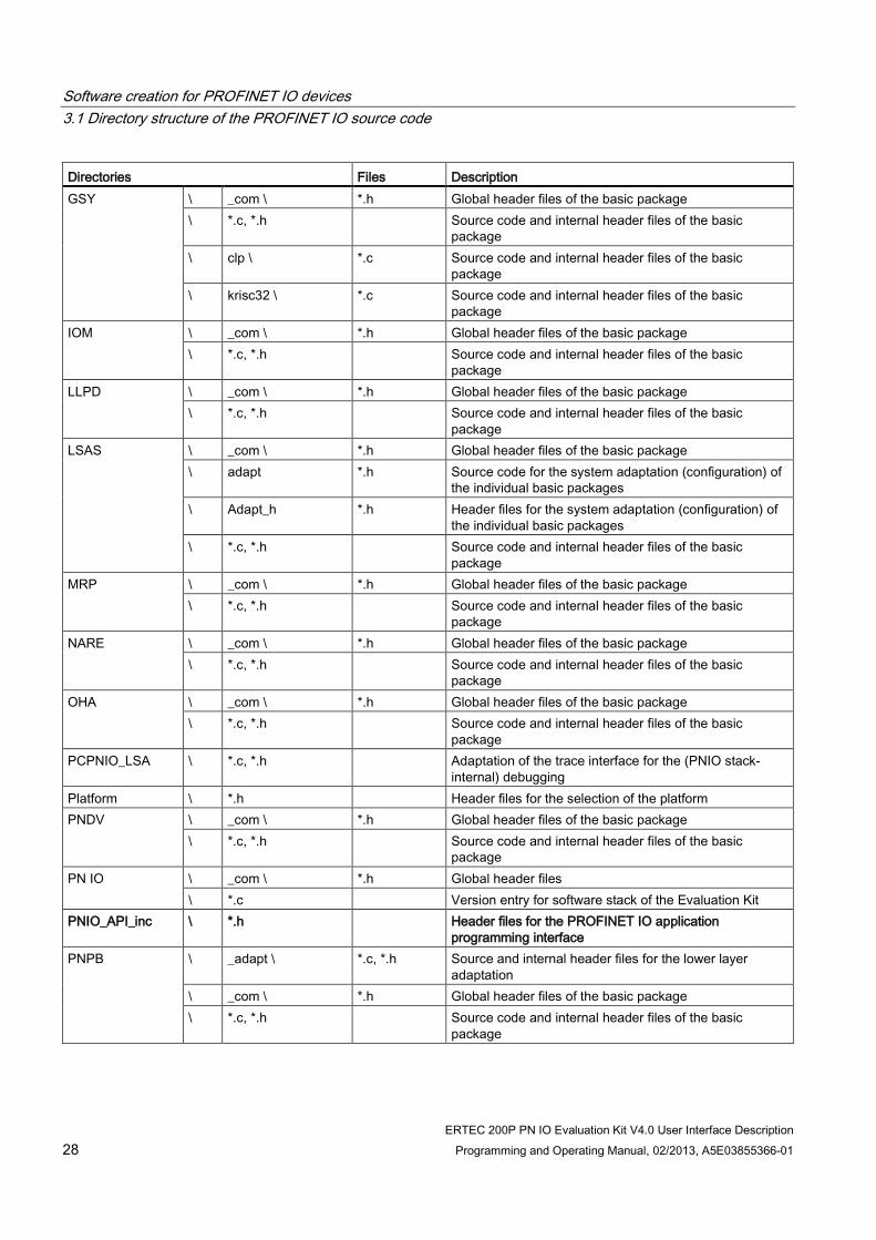
3.1 Directory structure of the PROFINET IO source code The allocation of the source code to various subdirectories is geared toward the software structure of the IO stack for PNIO devices. The following table provides an overview.
Table 3- 1 Structure and description of the directories
Directories Files Description Appl_startup \ main_xx.c Entry point into the PROFINET IO software. Start the IO
main task, mainAppl() Application \ App1_Standard *.c, *.h Standard application example for RT and IRT, uses the
standard interface (SI) for IO data access \ App2_DBAI *.c, *.h Direct buffer access (DBAI) application example for RT
and IRT \ App_Common *.c, *.h Common modules, used by the various application
examples. ACP \ _com \ *.h Global header files of the basic package
\ *.c, *.h Source code and internal header files of the basic package
CLRPC \ _com \ *.h Global header files of the basic package \ *.c, *.h Source code and internal header files of the basic
package CM \ _com \ *.h Global header files of the basic package
\ *.c, *.h Source code and internal header files of the basic package
DCP \ _com \ *.h Global header files of the basic package \ *.c, *.h Source code and internal header files of the basic
package EDDP (for ERTEC 200P platform only)
\ _com \ *.h Global header files of the basic package \ *.c, *.h Source code and internal header files of the basic
package \ xxx \ *.c Other internal subdirectories of the basic package, here
summarized as \xxx\ EVMA (for ERTEC 200P platform only)
\ _com \ *.h Global header files of the component \ *.c, *.h Source code and internal header files of the component
Software creation for PROFINET IO devices 3.1 Directory structure of the PROFINET IO source code
ERTEC 200P PN IO Evaluation Kit V4.0 User Interface Description 28 Programming and Operating Manual, 02/2013, A5E03855366-01
Directories Files Description GSY \ _com \ *.h Global header files of the basic package
\ *.c, *.h Source code and internal header files of the basic package
\ clp \ *.c Source code and internal header files of the basic package
\ krisc32 \ *.c Source code and internal header files of the basic package
IOM
\ _com \ *.h Global header files of the basic package \ *.c, *.h Source code and internal header files of the basic
package LLPD \ _com \ *.h Global header files of the basic package
\ *.c, *.h Source code and internal header files of the basic package
LSAS \ _com \ *.h Global header files of the basic package \ adapt *.h Source code for the system adaptation (configuration) of
the individual basic packages \ Adapt_h *.h Header files for the system adaptation (configuration) of
the individual basic packages \ *.c, *.h Source code and internal header files of the basic
package MRP \ _com \ *.h Global header files of the basic package
\ *.c, *.h Source code and internal header files of the basic package
NARE \ _com \ *.h Global header files of the basic package \ *.c, *.h Source code and internal header files of the basic
package OHA \ _com \ *.h Global header files of the basic package
\ *.c, *.h Source code and internal header files of the basic package
PCPNIO_LSA \ *.c, *.h Adaptation of the trace interface for the (PNIO stack-internal) debugging
Platform \ *.h Header files for the selection of the platform PNDV \ _com \ *.h Global header files of the basic package
\ *.c, *.h Source code and internal header files of the basic package
PN IO \ _com \ *.h Global header files \ *.c Version entry for software stack of the Evaluation Kit
PNIO_API_inc \ *.h Header files for the PROFINET IO application programming interface
PNPB \ _adapt \ *.c, *.h Source and internal header files for the lower layer adaptation
\ _com \ *.h Global header files of the basic package \ *.c, *.h Source code and internal header files of the basic
package

Software creation for PROFINET IO devices 3.1 Directory structure of the PROFINET IO source code
ERTEC 200P PN IO Evaluation Kit V4.0 User Interface Description Programming and Operating Manual, 02/2013, A5E03855366-01 29
Directories Files Description POF \ _com \ *.h Global header files of the basic package
\ dmi \ *.c Source code and internal header files of the basic package
\ edd \ *.c Source code and internal header files of the basic package
\ prm\ *.c Source code and internal header files of the basic package
\ *.c, *.h Source code and internal header files of the basic package
SOCK \ _com \ *.h Global header files of the basic package \ *.c, *.h Source code and internal header files of the basic
package SYS \ _cfg \ *.h Configuration files for ERTEC 200P, LSAS, PNDV,
TRACE \ _inc \ *.h Header files for the basic package \ *.c, *.h Source code and internal header files of the basic
package SysAdapt1 \ cfg \ *.c, *.h Modules to be adapted by the user
Platform independent example code for OS abstraction layer Upper and lower layer interface to the TCP/IP stack MIB2 adaptation BSP adaptation
\ inc \ *.h Global header files for the system adaptation \ src \ *.c Source code of the system adaptation that can generally
be used without modification TCPIP \ _com \ *.h Global header files of the basic package
\ Allports \ *.c, *.h Source code / header files of the package \ h \ *.c, *.h Internal header files of the basic package \ lp \ *.c, *.h Source code / header files of the IP protocol \ lpmc \ *.c, *.h Source code / header files of the IPMC protocol \ Misclib \ *.c, *.h Source code / header files for the checksum calculation \ Net \ *.c, *.h Source code / header files lower layer adaptation \ Snmp \ *.c, *.h Source code / header files of the SNMP protocol \ Snmpv1 \ *.c, *.h Source code / header files of the SNMP protocol \ tcp \ *.c, *.h Source code / header files of the TCP protocol \ *.c, *.h Source code and internal header files of the basic
package Trace_dk \ trace_dk.c
trace_dk.h Storage of error messages in a circular buffer or output to the TeraTerm console (connected via the RS232 interface) as a debugging aid
\ Traceout_con \ *.c, *.h Output of the messages to the TeraTerm console \ Traceout_mem \ *.c, *.h Outputs of the messages to a circular buffer and to the
TeraTerm console output (default)

Software creation for PROFINET IO devices 3.2 Files for the application examples
ERTEC 200P PN IO Evaluation Kit V4.0 User Interface Description 30 Programming and Operating Manual, 02/2013, A5E03855366-01
3.2 Files for the application examples
3.2.1 Files for App1_STANDARD Module Content Description usriod_main.c Main program for RT
and IRT Example
Standard application example, main program for RT and IRT Class 2, IRT Class 3. Startup of the IO stack, main loop with functions initiated by keyboard for an RT application
iodapi_event.c Signaling of events to the application
Event handlers for the application examples Standard RT, IRT Class 2, and IRT Class 3 Contains functions that the IO stack calls when events occur such as the establishment/termination of connections, reception of alarms, etc., and thereby notifies the application of their occurrence. Users must implement these functions according to their requirements.
PnUsr_Api.c Subroutines Subroutines for the user example. The functions contained can be used as a function library in the customer application, if needed.
3.2.2 Files for App2_DBAI Module Content Description usriod_main_dbai.c Main program for
the DBA example DBAI application example main program Start of the IO stack, main loop with functions initiated by keyboard for a DBA application (Direct Buffer Access)
usriod_main_dbai.h Header file Header file for usriod_main_dbai.c iodapi_event_dbai.c Signaling of events
to the application Event handler, only for the application example in usriod_main_dbai.c.
3.2.3 Files for App3_IsoApp Module Content Description usriod_main_isoapp.c Main program for
RT and IRT example
Standard user example, the main program for IRT Class 3 with isochronous IO submodules
iodapi_event_isoapp.c Signaling of events to the application
Event handler for user examples standard IRT C3 with isochronous IO submodules. Enables ERTEC comparators for handing T_Input and T_Output times based on the data in record index 0x8030. The required configurations of GPIOs (5, 7) are performed using the "PNIO_IsoActivateGpioObj()" function in this case. Note: Time-controlled interrupts can be enabled using "PNIO_IsoActivateIsrObj()". You can find an example for this in "usrio_main_isoapp.c", "W" or "w" key on the console.

Software creation for PROFINET IO devices 3.2 Files for the application examples
ERTEC 200P PN IO Evaluation Kit V4.0 User Interface Description Programming and Operating Manual, 02/2013, A5E03855366-01 31
3.2.4 Files for App_common
Table 3- 2 Files for the application example
Module Content Description iodapi_event.h Header file Header file for iodapi_event.c, may be adopted unchanged. iodapi_rema.c Retentive data Transfer of retentive data (PDEV records) from the PNIO stack to the
application for the purpose of storing them in non-volatile memory. iodapi_log.c Logging of debug and
error messages Central signaling of errors and notes to the application, logging for debug purposes or initiation of error handling routines. The functions are called by the stack and must be implemented by users according to their requirements. Empty functions can also be implemented.
Perform_measure.c Measuring the processor load
Optional performance measurement in the Idle Task (only intended for user example, not for a real device).
Perform_measure.h Measuring the processor load
Header file for perform_measure.h
Tcp_flash_fw.c FW download via TCP Main program for TCP-based services for transferring and flashing a new firmware.
TCP_IF.c FW download via TCP TCP-based services for the transfer of new firmware. Tcp_IF.h FW download via TCP Header file for tcp_if.c Tcp_Flash_fw.c FW flashing Transfer and flashing of new firmware via TCP/IP usriapp_cfg.h Selection of a user
example A define is used to select the corresponding user example (RT, IRT Class 3, DBA Interface).
usriod_cfg.h Configuration of the example
Defines for the configuration of the device
usriod_diag.c Application program for diagnostics
Example for the handling of standard channel diagnostics including diagnostic alarm.
usriod_diag.h Header file Header file for usriod_diag.c, contains data structure definitions for the standard channel diagnostics, among other things
usriod_PE.c PROFIenergy Application example for the handling of a PROFIenergy record usriod_PE.h PROFIenergy Header file for usrioed_PE.c usriod_utils.c Utilities Utilities to measure the system load for debugging purposes usriod_utils.h Header file Header file for usriod_utils.c

Software creation for PROFINET IO devices 3.2 Files for the application examples
ERTEC 200P PN IO Evaluation Kit V4.0 User Interface Description 32 Programming and Operating Manual, 02/2013, A5E03855366-01
3.2.5 Application interface The header files that define the application interface are stored in the "...\PNIO_API_inc" subdirectory. These files must not be changed.
Table 3- 3 Header files for the application interface
Module Content Description pniousrd.h Macros and definitions Contains global structures and definitions for the PROFINET IO application
programming interface. pniobase.h Macros and definitions Contains data types, constants and function declarations for the IO controller
functionality of the IO application programming interface. pnioerrx.h Macros and definitions Contains the error codes. Pnio_trace.h Macros and definitions Trace interface (redirection to the LSA trace). Iodapi_rema.h Macros and definitions Contains data types and constants of the REMA interface.
3.2.6 Operating system interface modules to be adapted
Table 3- 4 Files for the operating system abstraction interface
Module Content Description xxx_os.c OS services Abstraction interface for operating system service calls, where xx stands for
the platform (for example, ecos, etc.). The mapping of PNIO calls to platform-dependent operating system functions occurs here.
os_cfg.h OS configuration System configurations for PNIO: Definition of system resources for PNIO (e.g. Mutex).
os_taskprio.h OS configuration System configurations for PNIO: Setting of task priorities compiler.h Compiler-specific
definitions Definition of compiler-specific settings.
compiler_stdlibs.h Integration of standard header files
Definition of standard header files to be included
3.2.7 Socket interface modules to be adapted
Table 3- 5 Files for the socket abstraction interface
Module Content Description xx_ossock_iniche.c Socket adaptation Optional, only used for Logadapt. Changes are usually not necessary.

Software creation for PROFINET IO devices 3.3 Important constraints for integrating an application
ERTEC 200P PN IO Evaluation Kit V4.0 User Interface Description Programming and Operating Manual, 02/2013, A5E03855366-01 33
3.2.8 Modules of the BSP interface
Table 3- 6 Files for adaptation to the board support package
Module Content Description xx_BspAdapt_Ertec.c BSP adaptation Interface from the IO stack to the ERTEC
3.2.9 Storage of retentive data
Table 3- 7 Files for the adaptation to retentive data
Module Content Description xx_nv_data.c Storage of retentive
data Interface for the storage of non-volatile data. This interface is only used by the application example and not by the PNIO stack itself. It may therefore be changed as needed.
xx_flash.h Storage of retentive data
Header files with function declarations for handling of the flash. Changes are usually not necessary.
3.2.10 Other files for system adaptation
Table 3- 8 Other files for system adaptation
Module Content Description hamaport.c GPIO settings Functions for configuring the GPIOs. Changes are usually not
necessary. ecos_os_debug.c Optional tools Advanced information about the used resources of the operating system
(tasks, memory, etc.). Can only be used for the eCos platform. Os_utils.c, Os_utils.h Optional tools Optional tools to manage a circular buffer, which can be used for
debugging purposes.
Software creation for PROFINET IO devices 3.3 Important constraints for integrating an application
ERTEC 200P PN IO Evaluation Kit V4.0 User Interface Description 34 Programming and Operating Manual, 02/2013, A5E03855366-01
3.3 Important constraints for integrating an application When integrating the PROFINET IO stack into a customer application, the following constraints have to be observed:
1. In a "PNIO_cbf_xxxx()" callback function, the application code to be performed should be as short as possible, because all callback events arriving from the CM are sequenced in a message queue, and the application code is called in the context of a PNPB interface task. This means a callback function cannot be called until the preceding callback function is finished.
2. No "PNIO_xxx()" API functions should be called in a "PNIO_cbf_xxxx()" callback function. Permitted exceptions are "PNIO_rec_set_rsp_async()", "PNIO_get_last_error()", "PNIO_printf (debugging)" and plug/pull submodules in the context of the ownership indication.
3. Each user task from whose context PROFINET IO service functions "PNIO_xxxx()" are called, must be created with "OsCreateThread()" and be started with "OsStartThread()". A message queue is thereby automatically assigned to the thread, which is used for (and exclusively reserved for) communication with the IOD.
4. Task priorities of the PROFINET IO stack are specified in "os_taskprio.h". Platform-dependent changes are necessary here. However, the priority hierarchy among the PROFINET IO tasks may not be changed. Application tasks should be lower than the stack priorities, if possible. With higher priority application tasks, it must be noted that the runtime performance of the stack can be influenced negatively.

Software creation for PROFINET IO devices 3.4 Porting the PROFINET IO software to another platform
ERTEC 200P PN IO Evaluation Kit V4.0 User Interface Description Programming and Operating Manual, 02/2013, A5E03855366-01 35
3.4 Porting the PROFINET IO software to another platform For an ERTEC-based platform, porting to other operating systems is usually not necessary. We therefore recommend using the eCos operating system platform that is already adapted, if possible. Nevertheless, porting remains possible. The following section therefore deals with porting of PROFINET IO software to any platform. The application itself is not considered here, because it must be replaced in any case by a customer application (based on the application example). Depending on the component being replaced, different changes must be made in the software. Basically the following versions can be considered here:
● Replacement of the evaluation board with customer hardware based on the same microcontroller and the same operating system (simplest case)
● Use of other compilers
● Use of different microcontrollers (not for ERTEC platforms)
● Use of other operating systems
3.4.1 Porting to customer hardware with the same microcontroller and the same OS To port the software to your own hardware platform without changing the operating system, you must adapt the board support package to your hardware. Other changes in the operating system interface, BSP interface or application interface (see Figure 1 (Page 16)) are generally not necessary.
See also ERTEC 200P (Page 16)

Software creation for PROFINET IO devices 3.4 Porting the PROFINET IO software to another platform
ERTEC 200P PN IO Evaluation Kit V4.0 User Interface Description 36 Programming and Operating Manual, 02/2013, A5E03855366-01
3.4.2 Use of other compilers/linkers The configuration of the compiler is done in the "auto_platform_select.h" file. A separate copy of this file exists in the "(...)Pnio_src\Platform" subdirectory for each platform. Only one "auto_platform_select.h" is included at a time by selecting the Include path.
3.4.2.1 Tool chain selection One and only one of the following defines may be used (unneeded defines of "TOOL_CHAIN_xxxx" must be commented out).
#define TOOL_CHAIN_GNU_ECOS 1 // #define TOOL_CHAIN_GENERIC_32BIT 1
If you do not use the default tool chain, you can enter your own compiler-specific defines most easily under "TOOL_CHAIN_GENERIC_32BIT". Generally, you only have to make adjustments to the "compiler.h" file.
It is also possible in principle to define your own compiler switch in "compiler.h". In this case, additions must be made at several places in the code. Therefore, search for all locations in the source code where one of the defines listed above is used, and insert your own compiler-switch dependent code.
3.4.2.2 Big Endian or Little Endian #define PNIO_BIG_ENDIAN 0 // Little Endian, z. B. ERTEC platform #define PNIO_BIG_ENDIAN 1 // Big Endian
3.4.2.3 Data alignment requirements The definition of the data alignment is often handled differently in different compilers. Some compilers use a #pragmapack() or #pragma unpack() instruction, whereby all definitions between two instructions are packed accordingly.
Other compilers expect a corresponding definition for each data structure that is located before or after the actual definition (depending on the compiler once again). For all three cases mentioned, the following mechanisms have been implemented in the PN stack:
● #include "sys_pck.h", #include "sys_unpck.h"
● #define ATTR_PNIO_PACKED_PRE
● #define ATTR_PNIO_PACKED
Select just one of these options depending on the compiler. The other two should be implemented as an empty macro or empty header file. The ATTR_PNIO_PACKED or ATTR_PNIO_PACKED_PRE macros are implemented in the "pnio_src \ sysadapt1 \ cfg \ compiler.h" file; the #pragma pack/unpack instructions, on the other hand, are implemented in the "pnio_src\sysadapt1\inc\sys_pck.h" or "sys_unpck.h" file.

Software creation for PROFINET IO devices 3.4 Porting the PROFINET IO software to another platform
ERTEC 200P PN IO Evaluation Kit V4.0 User Interface Description Programming and Operating Manual, 02/2013, A5E03855366-01 37
3.4.2.4 Data processing capacity To date, the software has been ported exclusively to IO controllers with 32-bit data processing. All data and address pointers are also 32 bits in length.
3.4.2.5 Memory management For the IO stack, there are no particular specifications for memory management. This means the IO stack can be located as desired, taking into account the alignment and memory management requirements of the hardware. Because some LSA layers require an 8-byte alignment, an 8-byte alignment was implemented for "OsAllocX" and "OsFreeX" in the example system adaptation. This requirement is thereby met even for operating systems, which themselves do not support this requirement.
For dynamic memory management, various memory pools can in principle be defined in the system adaptation in "os.h"; these are referenced in the software when memory is allocated. This mechanism is currently not utilized; only the following pool is defined:
#define MEMPOOL_DEFAULT 0 // may be cached
3.4.3 Use of other operating systems The task priorities of the PROFINET IO tasks can be set in "os_taskprio.h". In so doing, the sequence of ascending priorities must not be changed. It must be noted that in some operating systems the lowest numeric value (priority = 0) represents the highest priority, while in others, the reverse applies.
The file "xx_OS.C" contains an operating system abstraction interface, which the user must adapt to the particular operating system. The functions of the operating system interface are described in detail in section Interface to the operating system (Page 96).

Software creation for PROFINET IO devices 3.5 Typical sequence of an IO device user program
ERTEC 200P PN IO Evaluation Kit V4.0 User Interface Description 38 Programming and Operating Manual, 02/2013, A5E03855366-01
3.5 Typical sequence of an IO device user program
Overview The typical sequence of an IO device user program is divided into 3 phases:
● Initialization phase
● Productive operation
● Completion phase
IO data access:
● Asynchronous IO data access with consistency mechanisms for RT and IRT (RT_CLASS3)
● Synchronous IO data access without consistency mechanisms, only for IRT (RT_CLASS3)
Refer to the detailed information below.

Software creation for PROFINET IO devices 3.5 Typical sequence of an IO device user program
ERTEC 200P PN IO Evaluation Kit V4.0 User Interface Description Programming and Operating Manual, 02/2013, A5E03855366-01 39
3.5.1 Initialization phase
Description The initialization phase is subdivided into several steps. Here, a distinction must be made between function calls that are made by the IO device user program and callback calls that are made by the IO interface.
Table 3- 9 API functions to be called during the startup phase
Step Action Objective System startup 0 System starts up and calls its main()
function
1 PNIO_init() "PNIO_init" initializes the OS interface, among other things, and must therefore be called once before all other PNIO functions.
2 OsCreateThread(MainAppl) OsCreateMsgQueue OsStartThread
With "OsCreateThread" the first PNIO user task, "MainAppl()", is started; it needs an OS message queue to communicate with the PNIO stack. All additional PNIO API calls must be made from "MainAppl()" or from another task that has also been created with "OsCreateThread()".
PROFINET stack startup 3 PNIO_setup() Startup of the PNIO stack, startup of all PNIO tasks and allocation
of resources Creating instances for devices, APIs, modules, submodules 4 PNIO_device_open() Creation of a device instance 5 PNIO_sub_plug() Inserts the PROFINET IO submodules of the IO device 6 PNIO_set_dev_state() Set device into OPERATE mode Wait for establishment of connection by the IO controller 7 Wait for a call of the PNIO_cbf_ar_
connect_ind() callback function. This callback is called by the IO interface as soon as an IO controller has established a connection to the IO device user program. When this callback is called, application relation global parameters are transferred to the IO device user program to be checked.
8 Wait for a call of the PNIO_cbf_ar_ ownership_ind() callback function.
The Ownership indication is called after the Connect indication disappears. Here, the application is passed a list of all submodules and their properties (slot, module/submodule ID, OwnerSessionKey, etc.). The OwnerSessionKey to is set to 0 in this callback function only if the application declines the ownership of a subslot, and thus does not want to process the submodule. Otherwise, the OwnerSessionKey remains unchanged. If an incorrect, incompatible submodule is plugged, the application must set the IsWrongSubmod parameter to PNIO_TRUE. Alternatively, the verification of the submodule ID can also be performed in the PN stack. Refer to the description of PNIO_cbf_ar_ownership_ind() function for details.

Software creation for PROFINET IO devices 3.5 Typical sequence of an IO device user program
ERTEC 200P PN IO Evaluation Kit V4.0 User Interface Description 40 Programming and Operating Manual, 02/2013, A5E03855366-01
Step Action Objective Parameter assignment of the submodules 9 React to a call of the
PNIO_cbf_rec_write() callback function. This callback is called by the IO interface in the event that an IO controller transfers a parameter assignment record for a submodule. When this callback is called, any parameter assignment data for each submodule is transferred to the IO device user program.
10 Wait for a call of the PNIO_cbf_param_ end_ind() callback function.
This callback is called by the IO interface of each configured submodule as soon as an IO controller signals the end of the parameter assignment phase. The application sends the return value, if the module is not working or not working correctly. Refer to the description of the PNIO_cbf_param_end_ind() function for details.
11 PNIO_initiate_data_write() With this call, the user program initiates a call of the "PNIO_CBF_DATA_WRITE()" callback so that the IO device user program can initialize the input data of the functional submodules and set the local status values to "GOOD". The local status values must be set to "BAD" for all non-functional submodules. Notice The PROFINET IO standard requires that the output data for all functional submodules are set to valid values, and that the local provider status for each one is set to "GOOD" before sending the ApplicationReady signal.
12 PNIO_initiate_data_ read() With this call, the user program initiates a call of the "PNIO_CBF_DATA_READ()" callback so it can set the local status values to "GOOD" for all output data of the functional submodules. The local status values must be set to "BAD" for all non-functional submodules. Notice The PROFINET IO standard requires that the local consumer status values be set to "GOOD" for all functional submodules before sending the ApplicationReady signal.
13 Wait for a call of the PNIO_cbf_ar_ indata_ind() callback function
This callback is called by the IO interface as soon as an IO controller has transferred IO data for the first time. Signaling the start of cyclic data exchange

Software creation for PROFINET IO devices 3.5 Typical sequence of an IO device user program
ERTEC 200P PN IO Evaluation Kit V4.0 User Interface Description Programming and Operating Manual, 02/2013, A5E03855366-01 41
3.5.2 Productive operation
Overview During productive operation, data is exchanged with the IO controller. This means:
● Reading/writing IO data
● Sending alarms and receiving their acknowledgements
● Reading/writing a record
Details of the data traffic are explained below.
Reading RT and IRT IO data IO data (output data from the perspective of the PNIO controller) are read in three steps when using the consistency control mechanisms of the ERTEC 200P:
Table 3- 10 API functions to be called for reading RT and IRT IO data
Step Action Objective 1 Wait for the
PNIO_CP_CBE_TRANS_END_IND event
With this event, the IO interface signals the device application program the end of sending input data on the bus. The associated callback function is registered once by the application by means of "PNIO_CP_cbf_register_Cbf".
2 PNIO_initiate_data_read() Signals read request to the IO interface. This causes the IO interface to perform Step 2. This call returns only after all submodules have been processed in Step 2.
3 PNIO_CBF_DATA_READ() The IO interface calls this callback for each submodule with output data and transfers information to the callback, including the pointer to a data buffer containing the output data received from the IO controller.
Writing RT and IRT IO data IO data (input data from the perspective of the PNIO controller) are written in three steps:
Table 3- 11 API functions to be called for writing RT and IRT IO data
Step Action Objective 1 Wait for the
PNIO_CP_CBE_TRANS_END_IND event
With this event, the IO interface signals the device application program the end of IO data transfer on the bus. The associated callback function is registered once by the application by means of "PNIO_CP_cbf_register_Cbf".
2 PNIO_initiate_data_write() Signals a write request to the IO interface. This causes the IO interface to perform Step 2. This call returns only after all submodules have been processed in Step 2.
3 PNIO_CBF_DATA_WRITE() The IO interface calls this callback for each submodule with input data and transfers information to the callback, including the pointer to a data buffer into which the input data that will sent to the IO controller are to be copied.

Software creation for PROFINET IO devices 3.5 Typical sequence of an IO device user program
ERTEC 200P PN IO Evaluation Kit V4.0 User Interface Description 42 Programming and Operating Manual, 02/2013, A5E03855366-01
Processing a read/write record request from the PNIO controller Processing a read record request As soon as the IO interface receives a read record request from the IO controller, it calls the callback function "PNIO_CBF_REC_READ()" that has been registered by the IO device user program. The application can provide the record data inside the callback function or can deliver it asynchronously at a later point in time.
● Synchronous reading of record data:
Table 3- 12 API functions to be called for synchronous reading of record data
Step Action Objective 1 PNIO_cbf_rec_read() Read record request to the application. The application provides
the data inside the callback function. After returning from the callback function, the request is completed from the application point of view.
● Asynchronous reading of record data:
Table 3- 13 API functions to be called for asynchronous reading of record data
Step Action Objective 1 PNIO_cbf_rec_read() Read record request from the stack to the application. The
application would like to provide the data asynchronously. 2 PNIO_rec_set_rsp_async() The application notifies the stack that the response will occur
asynchronously. "PNIO_rec_set_rsp_async" must be called inside the callback function.
3 PNIO_rec_read_rsp() The application asynchronously transfers the requested record data to the stack. "PNIO_rec_read_rsp" can be called from any user task.
Processing a write record request As soon as the IO interface receives a write record request from the IO controller, it calls the callback function "PNIO_CBF_REC_WRITE()". The application can signal the stack of the completion of the write process synchronously when exiting the callback function or asynchronously at a later time.
● Synchronous writing of record data:
Table 3- 14 API functions to be called for synchronous writing of record data
Step Action Objective 1 PNIO_cbf_rec_write() Write record request to the application. The application
processes the data inside the callback function. After returning from the callback function, the request is completed from the application point of view.

Software creation for PROFINET IO devices 3.5 Typical sequence of an IO device user program
ERTEC 200P PN IO Evaluation Kit V4.0 User Interface Description Programming and Operating Manual, 02/2013, A5E03855366-01 43
● Asynchronous writing of record data:
Table 3- 15 API functions to be called for asynchronous writing of record data
Step Action Objective 1 PNIO_cbf_rec_write() Write record request from the stack to the application. The application
would like to provide the response asynchronously. 2 PNIO_rec_set_rsp_async() The application notifies the stack that the response will occur
asynchronously. "PNIO_rec_set_rsp_async" must be called inside the callback function.
3 PNIO_rec_write_rsp() The application asynchronously signals the stack about the completion of the request and includes status information. "PNIO_rec_write_rsp" can be called from any user task.
Sending alarms and receiving their alarm acknowledgements Each time an alarm is sent, the IO device user program receives an alarm acknowledgement; this occurs when the IO interface calls the "PNIO_cbf_async_req_done()" function. The assignment of an acknowledgment to a given alarm is made with the type of alarm and the fault location "AR number/API/Slot/Subslot."
Note
Alarms may only be sent to the IO device user program when the PNIO_cbf_param_end() function is completed.
Callback events during the establishment/termination of connections at the IO device When an application relation is established, information is made available by the IO interface by means of a callback.
The table below lists the “flagged information” and the associated callback names.
Table 3- 16 API callback functions for establishing/terminating a connection
Callback name Flagged information PNIO_cbf_ar_connect_ind Connection request from the IO controller PNIO_cbf_ar_ownership_ind Specified configuration of the PNIO device, RT Class (RT Class 1/3) and other
submodule properties PNIO_cbf_rec_write_ind Write a parameter record for a subslot PNIO_cbf_param_end_ind End of parameter assignment by PNIO controller PNIO_cbf_indata_ind ApplicationRelation-InData – First valid data has been received by the PNIO
controller. PNIO_cbf_disconn_ind DisconnectEvent – Close connection

Software creation for PROFINET IO devices 3.6 Basic data traffic in the IO device user interface
ERTEC 200P PN IO Evaluation Kit V4.0 User Interface Description 44 Programming and Operating Manual, 02/2013, A5E03855366-01
Note
These services involve passive functionality. All of these callbacks are called by the PROFINET library, generally in response to PROFINET IO controller actions.
3.5.3 Completion phase (The completion phase of the IO device is currently not implemented.)
3.6 Basic data traffic in the IO device user interface
Description The IO device functions have two basic mechanisms for data traffic:
Cyclic IO data traffic:
● Writing IO data
● Reading IO data
The IO data traffic is also accompanied by status information. This particular feature is described in the following section.
Acyclic data traffic:
● Reading and writing records
● Sending alarms and receiving their acknowledgements
Additional information on this topic can be found in section Callback mechanism (Page 52).

Software creation for PROFINET IO devices 3.7 Cyclic IO data traffic of the IO device user interface
ERTEC 200P PN IO Evaluation Kit V4.0 User Interface Description Programming and Operating Manual, 02/2013, A5E03855366-01 45
3.7 Cyclic IO data traffic of the IO device user interface
Basic mode of operation When IO data are written or read by the IO device user program, only the local process image on the device is written or read; in doing so, no data are sent over the network.
Data traffic between the local process image and the IO controller is independently and cyclically processed by the underlying stack functions or the by the hardware. The details of this data traffic are specified in the configuration.
Note
The IO device user program is not required to read or write IO data in every bus cycle.
Note
The IO device user program is not required to access the process image more often than the configured cycle.
Note
The data of a submodule are always transferred consistently. According to the PROFINET IO standard, a PROFINET device (controller and device) must be able to consistently transfer at least 254 bytes. This should be taken into consideration in conjunction with a PROFINET IO controller.
IO data and data status The quality of the IO data is described by the data status, which can take the values "GOOD" or "BAD".
Two data states are exchanged with every read or write:
● Local status (status of your IO device user program)
● Remote status (status of the communication partner)

Software creation for PROFINET IO devices 3.7 Cyclic IO data traffic of the IO device user interface
ERTEC 200P PN IO Evaluation Kit V4.0 User Interface Description 46 Programming and Operating Manual, 02/2013, A5E03855366-01
3.7.1 Cyclic writing with status
Sequence of the write operation to the process image The IO device user program initiates the write operation by calling the "PNIO_initiate_data_write()" function. The IO interface then calls the "PNIO_cbf_data_write" callback for each submodule that has been placed in service by the IO controller. The input data and the associated local provider status of this data are written into the local process image in this function.
Local status Normally, the IO device user program sets the local provider status of the input data to "GOOD".
If the input data is corrupt or invalid, the IO device user program must set the local provider status to "BAD". The communication partner could then, for example, output configured substitute values.
Remote status of the communication partner The communication partner uses the "remote consumer status" to signal whether it was able to process the input data ("good"), or whether a fault is present in the communication partner.
When using the standard interface (IO data communication initiated by "PNIO_initiate_data_read" and "PNIO_initiate_data_write"), this information is not transmitted to the application because it is usually not needed there. The remote consumer status of the input data can be read from the IOCR data with the DBA interface.

Software creation for PROFINET IO devices 3.7 Cyclic IO data traffic of the IO device user interface
ERTEC 200P PN IO Evaluation Kit V4.0 User Interface Description Programming and Operating Manual, 02/2013, A5E03855366-01 47
3.7.2 Cyclic reading with status
Sequence of the "PNIO_cbf_data_read()" function The IO device user program initiates the read operation by calling the "PNIO_initiate_data_read()" function. Then the IO interface calls the "PNIO__cbf_data_read()" callback function for each submodule with output data that has been placed in service by the IO controller. With the call of the callback function, the output data and the associated remote provider status of the communication partner is read from the local process image (stack-internal) and transferred to the application. In addition, the communication partner writes the local consumer status for these output data to the local process image. Two states are thus involved in cyclic read operations:
Communication direction Values From the communication partner • Output data
• Remote provider status
To the communication partner Local consumer status
Remote status of the communication partner The communication partner uses the remote provider status to signal the quality of the output data ("GOOD" or "BAD").
If the communication partner reports the provider status "BAD", IO data in the IO device user program cannot be further processed; the IO device user program could then, for example, output substitute values.
Local status Normally, the IO device user program sets the local status to "GOOD".
However, if the IO device user program cannot continue processing the supplied output data, the local status should be set to "BAD" when a read request is issued. As soon as the communication partner receives this status, it can determine whether the output data it sent was able to be processed further.
3.7.3 Cyclic data communication using the optional DBA interface The IO data can also be exchanged by using an optional DBA (Direct Buffer Access) interface. The application gains direct access to the IOCR and can directly write/read IO data and the IOxS to/from the individual submodules. This functionality provides performance advantages when there are a large number of submodules, because it is not necessary to execute a callback for every submodule. For more information, refer to section Cyclic data exchange by means of the optional DBA interface (Page 79).
The DBA interface can be used in all RT classes (RT, IRT).

Software creation for PROFINET IO devices 3.8 IO data communication for IRT class 3 (ERTEC-based platforms)
ERTEC 200P PN IO Evaluation Kit V4.0 User Interface Description 48 Programming and Operating Manual, 02/2013, A5E03855366-01
3.8 IO data communication for IRT class 3 (ERTEC-based platforms) The user interface is the same for RT and IRT. In both cases, IO data communication can be triggered by the same callback function as that for the "TransmissionEnd" event.
3.9 Managing diagnostic data
Description Diagnostics can be reported in the following ways with PROFINET IO:
● Standard channel diagnostics
● Extended channel diagnostics
● Manufacturer-specific diagnostics
The PROFINET stack automatically sends an entry "Diagnostic alarm - incoming" to the PROFINET IO controller when a new diagnostic entry is received. When the diagnostic entry is cleared, the corresponding "Diagnostic alarm - outgoing" is sent.
3.9.1 Channel diagnostic data In PROFINET IO , a submodule can consist of several channels. Multiple “channel diagnostic data" can exist for each channel. The IO device user program can create them in the submodule using the "PNIO_diag_channel_add()" function.
If "channel diagnostic data" is no longer valid, the IO device user program must clear the diagnostic entry from the submodule using the "PNIO_diag_channel_remove()" function.
The following functions are available for managing diagnostic data:
Table 3- 17 API functions to be called for the creation of a diagnostic record
Function Objective PNIO_diag_channel_add() Stores the channel diagnostic data in the subslot PNIO_diag_channel_remove() Removes the channel diagnostic data from the subslot PNIO_ext_diag_channel_add() Stores the channel diagnostic data in the subslot PNIO_ext_diag_channel_remove() Clears the channel diagnostic data in the subslot

Software creation for PROFINET IO devices 3.9 Managing diagnostic data
ERTEC 200P PN IO Evaluation Kit V4.0 User Interface Description Programming and Operating Manual, 02/2013, A5E03855366-01 49
Setting channel diagnostic data Channel diagnostic data is set in two steps:
Table 3- 18 API functions to be called for the activation of a created diagnostic record
Step Action Objective 1 PNIO_diag_channel_add() Stores the channel diagnostic data in the subslot
The stack automatically generates a "Diagnostic alarm - incoming" for the IO controller.
2 PNIO_cbf_async_req_done() "Diagnostic alarm - incoming" - evaluate acknowledgment.
Clearing channel diagnostic data Channel diagnostic data is cleared in two steps:
Table 3- 19 API functions to be called for the removal of a diagnostic record
Step Action Objective 1 PNIO_diag_channel_remove() Clears the channel diagnostic data from the
submodule. The stack automatically generates a "Diagnostic alarm - outgoing" for the IO controller.
2 PNIO_cbf_async_req_done() "Diagnostic alarm - outgoing" - evaluate acknowledgment.

Software creation for PROFINET IO devices 3.9 Managing diagnostic data
ERTEC 200P PN IO Evaluation Kit V4.0 User Interface Description 50 Programming and Operating Manual, 02/2013, A5E03855366-01
3.9.2 Manufacturer-specified diagnostic data "Manufacturer-specific diagnostic data" offers the IO device user program the option of storing its own manufacturer-specific diagnostic data for a submodule. There is no structure definition within the "manufacturer-specific diagnostic data".
The channel properties must also be specified for manufacturer-specific diagnostic data. For details, see /1/.
The following functions are available for managing this diagnostic data:
Table 3- 20 API functions to be called for the creation a generic diagnostic record
Function Objective PNIO_diag_generic_add() Stores the manufacturer-specific diagnostic data in
the subslot. The stack automatically generates a "Generic alarm - incoming" for the IO controller.
PNIO_diag_generic_remove() Removes the manufacturer-specific diagnostic data from the subslot. The stack automatically generates a "Generic alarm - outgoing" for the IO controller.
Setting manufacturer-specific diagnostic data Manufacturer-specific diagnostic data is set in two steps:
Table 3- 21 API functions to be called for the activation a generic diagnostic record
Step Action Objective 1 PNIO_diag_generic_add() Stores the manufacturer-specific diagnostic data in
the subslot. The stack automatically generates a "Generic alarm - incoming" for the IO controller.
2 PNIO_cbf_ async_req_done() Generic alarm- incoming - evaluate acknowledgment.
Clearing manufacturer-specific diagnostic data Manufacturer-specific diagnostic data is cleared in two steps:
Table 3- 22 API functions to be called for the removal of a generic diagnostic record
Step Action Objective 1 PNIO_diag_generic_remove() Removes the manufacturer-specific diagnostic data
from the submodule. The stack automatically generates a "Generic alarm - outgoing" for the IO controller.
2 PNIO_cbf_ async_req_done() Generic alarm - outgoing - evaluate acknowledgment.

Software creation for PROFINET IO devices 3.10 Details when inserting and removing modules during productive operation
ERTEC 200P PN IO Evaluation Kit V4.0 User Interface Description Programming and Operating Manual, 02/2013, A5E03855366-01 51
3.10 Details when inserting and removing modules during productive operation
Alarm for pulling submodules The PROFINET stack generates a PROFINET IO pull alarm as soon as the IO device user program pulls a module or a submodule with the following functions:
● PNIO_sub_pull()
Alarm for plugging submodules The IO interface generates a PROFINET IO plug alarm as soon as the IO device user program plugs in a module or a submodule with the following functions:
● PNIO_sub_plug()
Note
Between the call of "PNIO_cbf_ar_ownership_ind" and the completion of the "PNIO_cbf_param_end_ind" function, modules may not be plugged or pulled.
Reassignment of parameters after plugging The IO controller reassigns parameters for the associated submodule after each "PNIO_sub_plug()". This means that the PNIO stack calls the "PNIO_cbf_rec_write()" function for each parameter assignment record transferred by the IO controller.
The IO interface signals the end of parameter assignment by calling the "PNIO_cbf_param_end()" function.
After parameter assignment, the IO device user program determines whether the inserted submodule is functional with the transferred parameter assignment.
● If "YES", the IO device user program must set the input data to be sent and the local status for the inputs and outputs of this submodule to "GOOD". After this, the IO device user program must close the "PNIO_cbf_param_end()" function with Return (PNIO_SUBMOD_STATE_RUN).
● If "NO", the IO device user program must set the local status for the inputs and outputs of this submodule to "BAD" and then close the "PNIO_cbf_param_end()" function with Return (PNIO_SUBMOD_STATE_STOP). If the module can provide valid data for the running AR at a later point, the status must be set to "GOOD" and a return-of-submodule alarm triggered (see next section).

Software creation for PROFINET IO devices 3.11 Callback mechanism
ERTEC 200P PN IO Evaluation Kit V4.0 User Interface Description 52 Programming and Operating Manual, 02/2013, A5E03855366-01
3.10.1 Special features with "Return of submodule"
Description When a fault occurs in an inserted submodule, the IO device user program must leave the local status for the inputs and outputs as "BAD". As a result, the input and output data are no longer valid for the user program on the assigned IO controller.
If the submodule is functional again, the IO device user program must set the local status for the inputs and outputs to "GOOD". Then the IO device user program must signal the transition from "BAD" to "GOOD" to the IO controller by calling the "PNIO_ret_of_sub_alarm_send()" function. The IO controller does not reassign parameters for the submodule due to the "Return of submodule" alarm.
The submodule is thus functional again.
3.11 Callback mechanism
Operating principle Callback functions are specified by the PNPB component of the PNIO stack.
A callback event is an asynchronous event that is started by the PNIO stack. It interrupts the flow of the user program, and starts the callback function in a separate thread. Synchronization techniques are therefore required.
Callback functions in the IO device The table below shows the callback events and callback event types in the IO device. It also shows how you can register a callback function and how a callback event is triggered.
Table 3- 23 Overview of the callback functions in the IO device
Callback event (asynchronous)
Callback event type Triggered by ...
Reading data PNIO_cbf_data_read User program by calling PNIO_initiate_data_read
Writing data PNIO_cbf_data_write User program by calling PNIO_initiate_data_write
Reading a record PNIO_cbf_rec_read IO controller Writing a record PNIO_cbf_rec_write IO controller Acknowledgement for an alarm send request
PNIO_cbf_async_req_done User program by calling: • PNIO_process_alarm_send • PNIO_diag_alarm_send • PNIO_ext_diag_alarm_send • PNIO_ret_of_sub_alarm_send • PNIO_upload_retrieval_alarm_send
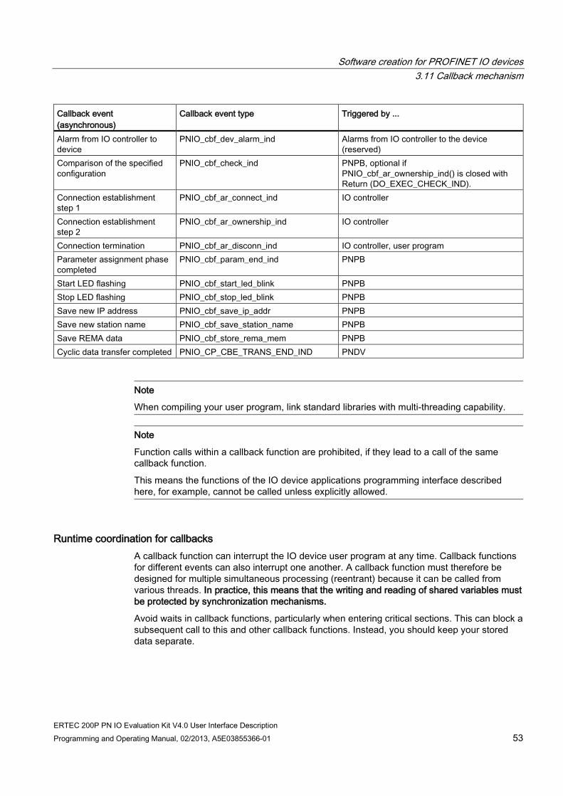
Software creation for PROFINET IO devices 3.11 Callback mechanism
ERTEC 200P PN IO Evaluation Kit V4.0 User Interface Description Programming and Operating Manual, 02/2013, A5E03855366-01 53
Callback event (asynchronous)
Callback event type Triggered by ...
Alarm from IO controller to device
PNIO_cbf_dev_alarm_ind Alarms from IO controller to the device (reserved)
Comparison of the specified configuration
PNIO_cbf_check_ind PNPB, optional if PNIO_cbf_ar_ownership_ind() is closed with Return (DO_EXEC_CHECK_IND).
Connection establishment step 1
PNIO_cbf_ar_connect_ind IO controller
Connection establishment step 2
PNIO_cbf_ar_ownership_ind IO controller
Connection termination PNIO_cbf_ar_disconn_ind IO controller, user program Parameter assignment phase completed
PNIO_cbf_param_end_ind PNPB
Start LED flashing PNIO_cbf_start_led_blink PNPB Stop LED flashing PNIO_cbf_stop_led_blink PNPB Save new IP address PNIO_cbf_save_ip_addr PNPB Save new station name PNIO_cbf_save_station_name PNPB Save REMA data PNIO_cbf_store_rema_mem PNPB Cyclic data transfer completed PNIO_CP_CBE_TRANS_END_IND PNDV
Note
When compiling your user program, link standard libraries with multi-threading capability.
Note
Function calls within a callback function are prohibited, if they lead to a call of the same callback function.
This means the functions of the IO device applications programming interface described here, for example, cannot be called unless explicitly allowed.
Runtime coordination for callbacks A callback function can interrupt the IO device user program at any time. Callback functions for different events can also interrupt one another. A callback function must therefore be designed for multiple simultaneous processing (reentrant) because it can be called from various threads. In practice, this means that the writing and reading of shared variables must be protected by synchronization mechanisms.
Avoid waits in callback functions, particularly when entering critical sections. This can block a subsequent call to this and other callback functions. Instead, you should keep your stored data separate.

Software creation for PROFINET IO devices 3.11 Callback mechanism
ERTEC 200P PN IO Evaluation Kit V4.0 User Interface Description 54 Programming and Operating Manual, 02/2013, A5E03855366-01
ERTEC 200P PN IO Evaluation Kit V4.0 User Interface Description Programming and Operating Manual, 02/2013, A5E03855366-01 55
Interface Description 4 4.1 Upper layer interface functions for the application
Functions to be implemented by the user All functions with the designation "Function call: IO Stack > Application" are not called by the application; instead they are called by the stack and must be implemented by the user. All of these functions have names starting with the prefix "PNIO_cbf_" because, logically speaking, a callback function is involved. For all of these functions, a simple example implementation is included which generally must be extended.
Synchronous and asynchronous functions In the case of a synchronous function, execution is already completed when the function returns.
In the case of asynchronous functions, however, completion of the execution is indicated by means of a callback function.
Whether a function operates synchronously or asynchronously is indicated in the description for the individual functions.

Interface Description 4.1 Upper layer interface functions for the application
ERTEC 200P PN IO Evaluation Kit V4.0 User Interface Description 56 Programming and Operating Manual, 02/2013, A5E03855366-01
4.1.1 Functions for system startup
4.1.1.1 PNIO_init PNIO_init() Function call: Application > IO Stack, synchronous This function initializes the adaptation interface from the PNIO stack to the operating system (OS) interface and the BSP interface. It must therefore be called first during startup once before any other PNIO function is called, for example, before the first PNIO task is created with "OsCreateThread()". Input - - Output - -
4.1.1.2 PNIO_setup PNIO_setup() Function call: Application > IO Stack, synchronous Starts the IO stack. This function is called once during startup from the PNIO task that had to be created with "OsCreateThread()". Station name, station type and IP suite (IP address, subnet mask, default router address) must be specified as transfer parameters. Input
PNIO_INT8* pStationName Pointer to the station name (may be a non-NULL-terminated string) PNIO_UINT32 StationNameLen Length of the station name string PNIO_INT8* pStationType Pointer to the station type (NULL-terminated string) PNIO_UINT32 IpAddr IP address of the device PNIO_UINT32 SubnetMask IP subnet mask PNIO_UINT32 DefRouterAddr IP default router
Output PNIO_UINT32 return Execution status: "PNIO_OK", "PNIO_NOT_OK"

Interface Description 4.1 Upper layer interface functions for the application
ERTEC 200P PN IO Evaluation Kit V4.0 User Interface Description Programming and Operating Manual, 02/2013, A5E03855366-01 57
4.1.1.3 PNIO_device_open PNIO_device_open() Function call: Application > IO Stack, synchronous Creates a device instance. The function is called once during startup (after "PNIO_setup()") for each device instance. The following parameters are transferred: device ID, vendor ID, instance ID, max. number of ARs, the device annotation and (optionally for reasons of interface compatibility to the EB 200P and CP1616, configurable using "#define" in compiler.h) a list of callback functions. The stack creates a handle for the device and writes it to the address specified by "pDevHndl". The device handle must be saved in the application and specified as a parameter for most of the "PNIO_" functions. Note: The multi-device functionality is currently not implemented; however the handle must still be specified correctly. Input
PNIO_UINT16 VendorId Vendor ID for the device; must be requested from the PROFIBUS user organization.
PNIO_UINT16 DeviceId Device ID; must be unique within a vendor's PNIO products. PNIO_UINT16 InstanceId Instance ID for the device (currently only InstanceId = 1 is
permitted) PNIO_ANNOTATION* pDevAnnotation Annotation structure; contains device type, order number,
product version, etc. PNIO_SNMP_LLDP* pSnmpPar Pointer of type "PNIO_SNMP_LLDP" to SNMP objects that are
registered in the LLDP MIB. PNIO_BOOL MrpCapabilityActive "PNIO_TRUE": MRP capability activated, "PNIO_FALSE": MRP
capability disabled. PNIO_UINT32* pDevHndl Pointer to address in which the IO stack returns the device
handle to the application. Output PNIO_UINT32 return Execution status: "PNIO_OK", "PNIO_NOT_OK"

Interface Description 4.1 Upper layer interface functions for the application
ERTEC 200P PN IO Evaluation Kit V4.0 User Interface Description 58 Programming and Operating Manual, 02/2013, A5E03855366-01
4.1.1.4 PNIO_async_appl_rdy PNIO_async_appl_rdy() Function call: Application > IO Stack, synchronous The "PNIO_async_appl_rdy()" function is only required if the ApplicationReady for a submodule should be delayed, because the parameter assignment for this submodule is not yet complete. Normally, the information regarding whether or not a submodule has started correctly after parameter assignment is already passed to the PNIO stack in the return value of the callback function "PNIO_cbf_param_end_ind()". For this, the application returns "PNIO_SUBMOD_STATE_RUN" (submodule OK) or "PNIO_SUBMOD_STATE_STOP" (submodule not OK) in the return value. The stack can then automatically generate an ApplicationReady frame for the PNIO controller and include it in the Moduldiffblock contained in the frame in the event of an error. However, if the parameter assignment of a submodule takes longer and the "PNIO_cbf_param_end_ind()" callback function should not be delayed, the ApplicationReady for this module can also be sent later. For this, "PNIO_cbf_param_end_ind()" first supplies the return value "PNIO_SUBMOD_STATE_APPL_RDY_FOLLOWS". Once the parameter assignment is complete, this information is "sent later" to the affected submodules using "PNIO_async_appl_rdy()". Input
PNIO_UINT32 DevHndl Device handle created by the stack using "PNIO_device_open()". PNIO_UINT16 ArNum Number of the affected AR PNIO_UINT32 Api API number PNIO_UINT16 SlotNum Slot number PNIO_UINT16 SubslotNum Subslot number PNIO_SUBMOD_STATE SubState Defines whether or not the module has started correctly. Possible
values are: • "PNIO_SUBMOD_STATE_RUN" • "PNIO_SUBMOD_STATE_STOP"
PNIO_BOOL MoreFollows • "PNIO_TRUE": The "PNIO_async_appl_rdy()" calls for additional submodules of this AR follow. The requests are only cached in the PNIO stack.
• "PNIO_FALSE": There are no further "PNIO_async_appl_rdy()" calls. All previous cached requests (MoreFollows = PNIO_TRUE) in the PNIO stack are processed, and the ApplicationReady frame for the PNIO controller is generated and sent.
Output PNIO_UINT32 return Execution status: "PNIO_OK", "PNIO_NOT_OK"
4.1.1.5 PNIO_device_close PNIO_device_close() Function call: Application > IO Stack, synchronous Not yet supported. Input PNIO_UINT32 DevHndl Device handle created by the stack using "PNIO_device_open()". Output PNIO_UINT32 Execution status: "PNIO_OK"

Interface Description 4.1 Upper layer interface functions for the application
ERTEC 200P PN IO Evaluation Kit V4.0 User Interface Description Programming and Operating Manual, 02/2013, A5E03855366-01 59
4.1.1.6 PNIO_CP_register_cbf PNIO_CP_register_cbf() Function call: Application > IO Stack, synchronous Callback functions can be registered for cyclic events in the PNIO stack with "PNIO_register_cbf()" to synchronize the application with the data transfer on the bus. Currently the event "PNIO_CP_CBE_TRANS_END_IND" is implemented. This function notifies the application that the data transfer for the current IO cycle has finished. The application can now access the IO data using "PNIO_initiate_data_read()" or "PNIO_initiate_data_write()". Input PNIO_CP_CBE_TYPE CbeType Specifies the event for which the callback is called. Currently the
event "PNIO_CP_CBE_TRANS_END_IND" is implemented. PNIO_CP_CBF pCbf Start address of the application function to be called by the PNIO
stack when the above-named event occurs. Output PNIO_UINT32 Execution status: "PNIO_OK"
4.1.2 Setting the device name and IP suite The Ethernet parameters (IP address, subnet mask, default router address) of the IO device can be set by a PROFINET IO controller via Ethernet. The station name of the device must have been set beforehand with the configuration tool.
For transferring this information to the application, functions which the user must implement are called by the IO stack. The application must store these data in non-volatile memory (NV RAM, Flash EPROM, etc.). The data is transferred again to the stack at the next system startup by means of the following function
● "PNIO_setup()"
To transfer the station name a function frame is placed in "iodapi_event.c" for the following function, which must be implemented by the user:
● "PNIO_cbf_save_station_name()"
Setting of the Ethernet parameters is basically performed in the same way by calling the function
● "PNIO_cbf_save_ip_addr()"
A blinking function can be started in the engineering tool. The addressed IO device is identified visually by a flashing LED. Activation of the LED is platform-dependent and, therefore, not contained directly in the IO stack. In this case, the IO stack calls the following functions, which the user must implement accordingly:
● "PNIO_cbf_start_led_blink" (flash frequency)
● "PNIO_cbf_stop_led_blink()"
With the following function, the factory settings must be restored:
● "PNIO_cbf_reset_factory_settings()"

Interface Description 4.1 Upper layer interface functions for the application
ERTEC 200P PN IO Evaluation Kit V4.0 User Interface Description 60 Programming and Operating Manual, 02/2013, A5E03855366-01
4.1.2.1 PNIO_cbf_save_station_name PNIO_cbf_save_station_name() Function call: IO stack > Application, synchronous If a new station name for the device is to be assigned for the device via Ethernet, the "PNIO_cbf_save_station_name()" function is called by the IO stack. The application must store the transferred station name in non-volatile memory, if the Retentive parameter is not equal to 0. The value is read by the application from the non-volatile memory at the next system startup and transferred to the stack again with the "PNIO_setup()" function. Input PNIO_INT8* pStationName Pointer to the string that contains the station name. (The station
name does not necessarily have to be null-terminated.) PNIO_UINT16 NameLength Length of the string in bytes PNIO_UINT8 Retentive <> 0: Data must be stored retentively
== 0: Value cannot be retentively saved and a name already stored must be deleted
Output PNIO_UINT32 return "PNIO_OK", "PNIO_NOT_OK"
4.1.2.2 PNIO_cbf_save_ip_addr PNIO_cbf_save_ip_addr() Function call: IO stack > Application, synchronous If a new IP address for the device is to be assigned for the device via Ethernet, the "PNIO_cbf_save_ip_addr()" function is called by the IO stack. The application must store the following parameters in non-volatile memory, if the "Retentive" parameter is not equal to zero: IP address, subnet mask, and default router. The value is read by the application from the non-volatile memory at the next system startup and transferred to the stack again with the "PNIO_set_eth_par()" function. Input PNIO_UINT32 NewIpAddr New IP address
PNIO_UINT32 SubnetMask New value for subnet mask PNIO_UINT32 DefRouterAddr New value for default router PNIO_UINT8 Retentive <> 0: Data must be stored retentively
== 0: Value cannot be retentively saved and values already stored must be deleted
Output PNIO_UINT32 return "PNIO_OK," "PNIO_NOT_OK"
4.1.2.3 PNIO_cbf_start_led_blink PNIO_cbf_start_led_blink() Function call: IO stack > BSP, synchronous If the flashing function is started in the engineering tool, the IO stack calls this function. The application can then put an LED (if present) into flashing mode at the specified frequency. The flashing process lasts about 3 seconds, and then the stack automatically calls "PNIO_cbf_stop_led_blink()" which ends the flashing process. Input PNIO_UINT32 DevHndl Device handle created by the stack using "PNIO_device_open()".
PNIO_UINT32 PortNum Port number (1 to n) PNIO_UINT32 Frequency Specified flashing frequency, in Hertz
Output PNIO_UINT32 return must be "PNIO_OK"

Interface Description 4.1 Upper layer interface functions for the application
ERTEC 200P PN IO Evaluation Kit V4.0 User Interface Description Programming and Operating Manual, 02/2013, A5E03855366-01 61
4.1.2.4 PNIO_cbf_stop_led_blink PNIO_cbf_stop_led_blink() Function call: IO stack > BSP, synchronous Turns the flashing mode of the LED off again. Input PNIO_UINT32 DevHndl Device handle created by the stack using "PNIO_device_open()". PNIO_UINT32 PortNum Port number (1 to n) Output PNIO_UINT32 return must be "PNIO_OK"
4.1.2.5 PNIO_cbf_reset_factory_settings PNIO_cbf_reset_factory_settings() Function call: IO stack > BSP, synchronous Reset to factory settings The application must reset all non volatile parameters (device name, IP suite, REMA data, etc.) to factory settings. After this the system must be restarted by the application so that the PNIO stack will reset its internal data. Input PNIO_UINT32 DevHndl Device handle created by the stack using
"PNIO_device_open()". Output PNIO_UINT32 return must be "PNIO_OK"
4.1.3 Storage of retentive data (REMA) In addition to the device name and IP suite, the records of the physical device (PDEV records) must be stored on the device in non-volatile memory. After the creation of the AR, the PDEV records are transferred from the PNIO controller to the device by means of "Record-Write" functions.
The records are temporarily stored by the PNIO stack and processed there. When all PDEV records have been received, they are recorded by the PNIO stack in a contiguous memory area and transferred to the application for persistent storage by means of a single call. The application therefore need not interpret the PDEV records, but only has to accept the entire data block and store it in non-volatile memory. The transfer of the PDEV data block from the PNIO stack is performed with the function
● "PNIO_cbf_store_rema_mem()".
A pointer to the data and the data length are passed as call parameters.
The next time the device starts up, the PNIO stack queries this information from the application. For this, the stack calls the function
● "PNIO_cbf_restore_rema_mem()"
The address of a pointer (**ppMem) is passed as a call parameter. The application enters the actual address of the REMA data there. A pointer to the data length is also passed, the application enters the actual data length there. It should be noted that the REMA data is not copied in this case and must therefore remain valid (static data) even after "PNIO_cbf_restore_rema_mem()" is completed.

Interface Description 4.1 Upper layer interface functions for the application
ERTEC 200P PN IO Evaluation Kit V4.0 User Interface Description 62 Programming and Operating Manual, 02/2013, A5E03855366-01
4.1.3.1 PNIO_cbf_store_rema_mem PNIO_cbf_store_rema_mem() Function call: IO stack > Application, synchronous Here all received PDEV records are transferred to the application in a contiguous data block for non-volatile storage. The application need only store the data block without change or interpretation in non-volatile memory and transfer it back to the stack at the next startup using "PNIO_restore_rema_mem()". Input PNIO_UINT32 MemSize Size of the data block in bytes
PNIO_UINT8* pMem Pointer to the data block Output PNIO_UINT32 return "PNIO_OK", "PNIO_NOT_OK"
4.1.3.2 PNIO_cbf_restore_rema_mem PNIO_cbf_restore_rema_mem() Function call: Application > IO Stack, synchronous With this function the application transfers the PDEV record data block, which has been stored in non volatile memory, back to the PNIO stack. This function must be called once during application startup, after the stack has started up, and the PDEV modules have been inserted. Input PNIO_UINT32* pMemSize Pointer to the data block size in bytes, the application must enter
the actual data length here. PNIO_UINT8** ppMem Address of the pointer to the data block. The application enters the
actual address of the REMA data here. The REMA data must be static, which means it must remain valid even after "PNIO_cbf_restore_rema_mem" is completed.
Output PNIO_UINT32 return "PNIO_OK", "PNIO_NOT_OK"

Interface Description 4.1 Upper layer interface functions for the application
ERTEC 200P PN IO Evaluation Kit V4.0 User Interface Description Programming and Operating Manual, 02/2013, A5E03855366-01 63
4.1.4 IO device configuration
4.1.4.1 PNIO_sub_plug PNIO_sub_plug() Function call: Application > IO Stack, synchronous Insertion of a new submodule into a subslot. The function is called during startup to specify the current configuration to the IO stack. It can also be called during operation in the event of changes to the current configuration, which means when a submodule that has failed or has been removed is once again functional. In this case, a plug alarm is automatically sent by the IO stack to the IO controller. A list of modules can be inserted by setting the parameter "MoreFollows" = "PNIO_TRUE". In this case, the modules can be stored temporarily in PNDV and passed later to the CM at the next insertion call with "MoreFollows PNIO_TRUE =". The feedback in "pError" is therefore only valid thereafter and can then be queried by the application. Note: During startup, the DAP and PDEV data "PNIO_sub_plug_list()" must be inserted first. Only then may additional modules be plugged in, either as additional entries in the "pIoSublist" submodule list or individually using the "PNIO_sub_plug()" function. Input PNIO_UINT32 DevHndl Device handle created by the stack using "PNIO_device_open()".
PNIO_UINT32 Api API number (default API is 0) PNIO_DEV_ADDR* pAddr Pointer to the insertion address (slot/subslot) of the submodule. Slot
numbers 1 to n are permitted; the maximum slot number was specified in "PNIO_setup()". "PNIO_ADDR_GEO" must be entered as the type.
PNIO_UINT32 ModIdent Module identifier (stored in the GSD file) PNIO_UINT32 SubIdent Submodule identifier (stored in the GSD file) PNIO_IM0_SUPP_ENUM Im0Support Specifies whether IM0 is supported and in which form, see enum
"PNIO_IM0_SUPP_ENUM" in the "pniousrd.h" file. IM0_DATA* plm0Dat If the module supports IM0 (Im0Support <> PNIO_IM0_NOTHING),
there is a pointer to the IM0 data here. Further handling of the IM0 data is perform internally in the stack.
PNIO_UINT8 IopsIniVal For submodules without IO data (e.g. PDEV submodules), the initial IOPS value for input modules is passed here (according to the PNIO standard, a submodule without data reacts like an input module with a data length of 0).
Output PNIO_UINT32 return Execution status: "PNIO_OK", "PNIO_NOT_OK"

Interface Description 4.1 Upper layer interface functions for the application
ERTEC 200P PN IO Evaluation Kit V4.0 User Interface Description 64 Programming and Operating Manual, 02/2013, A5E03855366-01
4.1.4.2 PNIO_sub_plug_list PNIO_sub_plug_list() Function call: Application > IO Stack, synchronous Insert a list of submodules in subslots. The function is called during startup to specify the current configuration to the IO stack. It can also be called during runtime in case the current configuration is changed. In this case, plug alarms are automatically sent by the IO stack to the IO controller. Note: During startup, the DAP and PDEV data must be inserted first with the "PNIO_sub_plug_list()". Only then may additional modules be plugged in, either as additional entries in the "pIoSublist" submodule list or individually using the "PNIO_sub_plug()" function. Either the DAP or the interface (subslot 0x8000) must serve as an IM0 proxy for the device, which means it must have its own IM0 data and the element "Im0Support" = (PNIO_IM0_SUBMODULE + PNIO_IM0_DEVICE) needs to be set in the submodule list. You can find a user example of this in file "usriod_main.c", structure "IoSubList []". Input
PNIO_UINT32 DevHndl Device handle created by the stack using "PNIO_device_open()".
PNIO_SUB_LIST_ENTRY*
pIoSubList List of submodules of the type "PNIO_SUB_LIST_ENTRY". It includes the slot number, module and submodule IDs, IM0 support yes/no.
PNIO_UINT32 NumOfSublistEntries Number of entries in the list of submodules PNIO_IM0_LIST_ENTRY* pIm0List List of IM0 data for those submodules that have their own
IM0 data PNIO_UINT32 NumOfIm0ListEntries Number of entries in the list of IM0 data PNIO_UINT32* pStatusList List of status feedback ("PNIO_OK", "PNIO_NOT_OK") for
each submodule in "pIoSubList". The status list therefore has the same number of entries as the submodule list.
Output PNIO_UINT32 return Group status: "PNIO_OK" if all individual feedback messages in "pStatusList" also contain "PNIO_OK"; otherwise "PNIO_NOT_OK" is reported back.
4.1.4.3 PNIO_sub_pull PNIO_sub_pull() Function call: Application > IO Stack, synchronous Removal of an inserted submodule. In this case, a pull alarm is automatically sent by the IO stack to the IO controller. Input PNIO_UINT32 DevHndl Device handle created by the stack using "PNIO_device_open()".
PNIO_UINT32 Api API number (default API is 0) PNIO_DEV_ADDR* pAddr Pointer to the insertion address (slot/subslot) of the submodule. Slot
numbers 1 to n are permitted; the maximum slot number was specified in "PNIO_setup()". "PNIO_ADDR_GEO" must be entered as the type.
Output PNIO_UINT32 return Execution status: "PNIO_OK", "PNIO_NOT_OK"

Interface Description 4.1 Upper layer interface functions for the application
ERTEC 200P PN IO Evaluation Kit V4.0 User Interface Description Programming and Operating Manual, 02/2013, A5E03855366-01 65
4.1.5 Storing diagnostic data in the subslot
4.1.5.1 PNIO_diag_channel_add PNIO_diag_channel_add() Function call: Application > IO Stack, synchronous Downloads a diagnostic record into a subslot. If the device is the owner of this subslot in an AR, a "Diagnostic alarm - incoming" is automatically sent to the IO controller. The diagnostic record can be removed with the "PNIO_diag_channel_remove()" function once the problem is rectified. Input
PNIO_UINT32 DevHndl Device handle created by the stack using "PNIO_device_open()".
PNIO_UINT32 Api API number (default API is 0) PNIO_DEV_ADDR* pAddr Pointer to the insertion address (slot/subslot) of the submodule.
"PNIO_ADDR_GEO" must be entered as the type. PNIO_UINT16 ChannelNum Channel number, content, and structure; see also
"ChannelNumber" in /1/ PNIO_UINT16 ErrorNum Error number, see also /1/ DIAG_CHANPROP_DIR ChainDir Data direction (IN/OUT/INOUT), see enum
"DIAG_CHANPROP_DIR" in the file "pniousrd.h" DIAG_CHANPROP_TYPE ChanType Data type (1-bit, 2-bit, ... BYTE, WORD, DWORD), see enum
"DIAG_CHANPROP_TYPE" in the file "pniousrd.h" PNIO_BOOL MaintenanceReq PNIO_TRUE: Maintenance required, else PNIO_FALSE PNIO_BOOL MaintenanceDem PNIO_TRUE: Maintenance demanded, else PNIO_FALSE
Output PNIO_UINT32 return Execution status: "PNIO_OK", "PNIO_NOT_OK"
4.1.5.2 PNIO_diag_channel_remove PNIO_diag_channel_remove() Function call: Application > IO Stack, synchronous Deletion of a diagnostic record that was downloaded with "PNIO_diag_channel_add()". The same values must be given for referencing as in the corresponding "PNIO_diag_channel_add" call. Input
PNIO_UINT32 DevHndl Device handle created by the stack using "PNIO_device_open()". PNIO_UINT32 Api API number (default API is 0) PNIO_DEV_ADDR* pAddr Pointer to the insertion address (slot/subslot) of the submodule.
"PNIO_ADDR_GEO" must be entered as the type. PNIO_UINT16 ChannelNum Channel number, content, and structure; see also
"ChannelNumber" in /1/ PNIO_UINT16 ErrorNum Error number, see also /1/ DIAG_CHANPROP_DIR ChanDir Data direction (IN/OUT/INOUT), see enum
"DIAG_CHANPROP_DIR" in the file "pniousrd.h" DIAG_CHANPROP_TYPE ChanTyp Data type (1-bit, 2-bit, ... BYTE, WORD, DWORD), see enum
"DIAG_CHANPROP_TYPE" in the file "pniousrd.h" Output PNIO_UINT32 return Execution status: "PNIO_OK", "PNIO_NOT_OK"

Interface Description 4.1 Upper layer interface functions for the application
ERTEC 200P PN IO Evaluation Kit V4.0 User Interface Description 66 Programming and Operating Manual, 02/2013, A5E03855366-01
4.1.5.3 PNIO_ext_diag_channel_add PNIO_ext_diag_channel_add() Function call: Application > IO Stack, synchronous Downloads an extended diagnostic record into a subslot. If the device is the owner of this subslot in an AR, an extended "Diagnostic alarm - incoming" is automatically sent to the IO controller. The diagnostic record can be removed with the "PNIO_ext_channel_remove()" function once the problem is rectified. Input
PNIO_UINT32 DevHndl Device handle created by the stack using "PNIO_device_open()".
PNIO_UINT32 Api API number (default API is 0) PNIO_DEV_ADDR* pAddr Pointer to the insertion address (slot/subslot) of the
submodule. "PNIO_ADDR_GEO" must be entered as the type.
PNIO_UINT16 ChanNum Channel number, content, and structure; see also "ChannelNumber" in /1/
PNIO_UINT16 ErrorNum Error number, see also /1/ DIAG_CHANPROP_DIR ChanDir Data direction (IN/OUT/INOUT), see enum
"DIAG_CHANPROP_DIR" in the file "pniousrd.h" DIAG_CHANPROP_TYPE ChanTyp Data type (1-bit, 2-bit, ... BYTE, WORD, DWORD), see
enum "DIAG_CHANPROP_TYPE" in the file "pniousrd.h" PNIO_UINT16 ExtChannelErrType Extended channel error type, content and structure; see
also "ExtChannelErrorType" in /1/ PNIO_UINT32 ExtChannelAddValue Additional value, content, and structure; see also
"ExtChannelAddValue" in /1/ PNIO_BOOL MaintenanceReg PNIO_TRUE: Maintenance required, else PNIO_FALSE PNIO_BOOL MaintenanceDem PNIO_TRUE: Maintenance demanded, else
PNIO_FALSE Output PNIO_UINT32 return Execution status: "PNIO_OK", "PNIO_NOT_OK"

Interface Description 4.1 Upper layer interface functions for the application
ERTEC 200P PN IO Evaluation Kit V4.0 User Interface Description Programming and Operating Manual, 02/2013, A5E03855366-01 67
4.1.5.4 PNIO_ext_diag_channel_remove PNIO_ext_diag_channel_remove() Function call: Application > IO Stack, synchronous Deletion of a diagnostic record that was downloaded with "PNIO_ext_diag_channel_add()". Input
PNIO_UINT32 DevHndl Device handle created by the stack using "PNIO_device_open()".
PNIO_UINT32 Api API number (default API is 0) PNIO_DEV_ADDR* pAddr Pointer to the insertion address (slot/subslot) of the
submodule. "PNIO_ADDR_GEO" must be entered as the type.
PNIO_UINT16 ChannelNum Channel number, content, and structure; see also "ChannelNumber" in /1/
PNIO_UINT16 ErrorNum Error number, see also /1/ DIAG_CHANPROP_DIR ChanDir Data direction (IN/OUT/INOUT), see enum
"DIAG_CHANPROP_DIR" in the file "pniousrd.h" DIAG_CHANPROP_TYPE ChanTyp Data type (1-bit, 2-bit, ... BYTE, WORD, DWORD), see
enum "DIAG_CHANPROP_TYPE" in the file "pniousrd.h" PNIO_UINT16 ExtChannelErrType Extended channel error type, content and structure; see
also "ExtChannelErrorType" in /1/ PNIO_UINT32 ExtChannelAddValue Additional value, content, and structure; see also
"ExtChannelAddValue" in /1/ Output PNIO_UINT32 return Execution status: "PNIO_OK", "PNIO_NOT_OK"

Interface Description 4.1 Upper layer interface functions for the application
ERTEC 200P PN IO Evaluation Kit V4.0 User Interface Description 68 Programming and Operating Manual, 02/2013, A5E03855366-01
4.1.5.5 PNIO_diag_generic_add PNIO_diag_generic_add() Function call: Application > IO Stack, synchronous Downloads a manufacturer-specific diagnostic record into a subslot. The diagnostic data can be read out by means of a special record call (see /1/), for example, by a diagnostic tool. Multiple diagnostic records that are referenced by a user-specifiable tag can be downloaded to a subslot. The diagnostic record can be removed with the "PNIO_diag_generic_remove()" function by means of this reference. Input
PNIO_UINT32 DevHndl Device handle created by the stack using "PNIO_device_open()".
PNIO_UINT32 Api API number (default API is 0) PNIO_DEV_ADDR* pAddr Pointer to the insertion address (slot/subslot) of the submodule.
"PNIO_ADDR_GEO" must be entered as the type. PNIO_UINT16 ChannelNum Channel number DIAG_CHANPROP_DIR ChanDir Data direction (IN/OUT/INOUT), see enum
"DIAG_CHANPROP_DIR" in the file "pniousrd.h" DIAG_CHANPROP_TYPE ChanTyp Data type (1-bit, 2-bit, ... BYTE, WORD, DWORD), see enum
"DIAG_CHANPROP_TYPE" in the file "pniousrd.h" PNIO_UINT16 DiagTag Unique reference to the record specified by the user PNIO_UINT16 UserStructIdent User structure identifier; see /1/:
0..7fff: Manufacturer-specific data in "pInfoData" PNIO_UINT8* pInfoData Pointer to the diagnostic data PNIO_UINT32 InfoDataLen Length of the diagnostic data in bytes PNIO_BOOL MaintenanceRe
q PNIO_TRUE: Maintenance required, else PNIO_FALSE
PNIO_BOOL MaintenanceDem
PNIO_TRUE: Maintenance demanded, else PNIO_FALSE
Output PNIO_UINT32 return Execution status: "PNIO_OK", "PNIO_NOT_OK"
4.1.5.6 PNIO_diag_generic_remove PNIO_diag_generic_remove() Function call: Application > IO Stack, synchronous Deletion of a diagnostic record that was downloaded with "PNIO_diag_generic_add()". Input
PNIO_UINT32 DevHndl Device handle created by the stack using "PNIO_device_open()". PNIO_UINT32 Api API number (default API is 0) PNIO_DEV_ADDR* pAddr Pointer to the insertion address (slot/subslot) of the submodule.
"PNIO_ADDR_GEO" must be entered as the type. PNIO_UINT16 ChanNum Channel number DIAG_CHANPROP_DIR ChanDir Data direction (IN/OUT/INOUT), see enum
"DIAG_CHANPROP_DIR" in the file "pniousrd.h" DIAG_CHANPROP_TYPE ChanTyp Data type (1-bit, 2-bit, ... BYTE, WORD, DWORD), see enum
"DIAG_CHANPROP_TYPE" in the file "pniousrd.h" PNIO_UINT16 DiagTag Unique reference to the record specified by the user PNIO_UINT16 UserStructIdent User structure identifier; see /1/:
0..7fff: Manufacturer-specific data in "pInfoData" Output PNIO_UINT32 return Execution status: "PNIO_OK", "PNIO_NOT_OK"

Interface Description 4.1 Upper layer interface functions for the application
ERTEC 200P PN IO Evaluation Kit V4.0 User Interface Description Programming and Operating Manual, 02/2013, A5E03855366-01 69
4.1.6 Sending and receiving alarms The following subslot-specific alarms can be triggered by means of the IOD API:
● Process alarms (optional)
● Diagnostic alarms (optional)
● "Return of submodule" alarms (mandatory)
Hardware and and diagnostic alarms can be triggered by the application if it has detected a relevant event. "Return of submodule" alarms must be triggered by the application if the user-data accompanying elements (IOPS, IOCS) change from "BAD" to "GOOD" during operation.
Implementation of the alarm functions is asynchronous, which means the function does not wait for the alarm to be acknowledged by the IO controller. Instead, after receipt of the alarm acknowledgement, the stack calls the "PNIO_cbf_async_req_done()" callback function which must be implemented by the user.
4.1.6.1 PNIO_process_alarm_send PNIO_process_alarm_send() Function call: Application > IO Stack, asynchronous Sends a (submodule-specific) process alarm to an IO controller. The accompanying data are contained in the alarm frame to the IO controller, but are not stored locally in the submodule. This means a remove function is not required. Input
PNIO_UINT32 DevHndl Device handle created by the stack using "PNIO_device_open()". PNIO_UINT32 Api API number (default API is 0) PNIO_DEV_ADDR*
pAddr Pointer to the insertion address (slot/subslot) of the submodule. "PNIO_ADDR_GEO" must be entered as the type.
PNIO_UINT8* pData Pointer to alarm data PNIO_UINT32 DataLen Length of alarm data, in bytes PNIO_UINT16 UserStructIdent User structure identifier; see /1/:
0..7fff: Manufacturer-specific data in "pData" PNIO_UINT32 UserHndl User-definable handle for differentiating several alarm send calls
running in parallel. The handle is transferred to the application as a transfer parameter of the "PNIO_cbf_async_req_done()" callback function after receipt of the alarm acknowledgement.
Output PNIO_UINT32 return Execution status: "PNIO_OK", "PNIO_NOT_OK"

Interface Description 4.1 Upper layer interface functions for the application
ERTEC 200P PN IO Evaluation Kit V4.0 User Interface Description 70 Programming and Operating Manual, 02/2013, A5E03855366-01
4.1.6.2 PNIO_upload_retrieval_alarm_send PNIO_upload_retrieval_alarm_send() Function call: Application > IO Stack, asynchronous With an upload/retrieval alarm, an event is sent to a central parameter server (iPar server). This event causes the iPar server to read a set of parameters from the device by means of a record read service or to transfer a set of parameters to the device by means of a record write service. A header that is part of the alarm data stores which record index is used and whether the data is to be read or written. You can find additional information on the function and handling of the upload/retrieval alarm in the document "45841087_FB24iParServ_DOKU_V10_en.pdf" in the subdirectory "\tools\TCI\iPar-Server" on the Product CD. Input
PNIO_UINT32 DevHndl Device handle created by the stack using "PNIO_device_open()". PNIO_UINT32 Api API number (default API is 0) PNIO_DEV_ADDR* *pAddr Pointer to the insertion address (slot/subslot) of the submodule.
"PNIO_ADDR_GEO" must be entered as the type. PNIO_UINT8* *pData Pointer to alarm data.
The data starts with a 24-byte long header. It determines the direction of transmission, the data length and the record index used. The structure of the header is defined in the PNIO specification. A user example is included in the application code, see "usriod_main.c" file, "UploadAlarmDate[]" and "RetrievalAlarmData[]" data structures.
PNIO_UINT32 DataLen Length of alarm data, in bytes. PNIO_UINT32 UserHndl User-definable handle for differentiating several alarm send calls
running in parallel. The handle is transferred to the application as a transfer parameter of the "PNIO_cbf_async_req_done()" callback function after receipt of the alarm acknowledgement.
Output PNIO_UINT32 return Execution status: "PNIO_OK", "PNIO_NOT_OK"
4.1.6.3 PNIO_ret_of_sub_alarm_send PNIO_ret_of_sub_alarm_send() Function call: Application > IO Stack, asynchronous Sends a "Return of submodule" alarm to the IO controller. The alarm must be issued by the device if the status of the user data-accompanying IOPS/IOCS changes from "BAD" to "GOOD" status. The response on the IO controller is similar to the response in the event of a plug alarm; however, the submodule does not have its parameters reassigned by the IO controller in the case of "PNIO_ret_of_sub_alarm_send()". Note: If, on the other hand, IOPS/IOCS changes from "GOOD" to "BAD", no alarm must be triggered. Input
PNIO_UINT32 DevHndl Device handle created by the stack using "PNIO_device_open()". PNIO_UINT32 Api API number (default API is 0) PNIO_DEV_ADDR* pAddr Pointer to the insertion address (slot/subslot) of the submodule.
"PNIO_ADDR_GEO" must be entered as the type. PNIO_UINT32 UserHndl User-definable handle for differentiating several alarm send calls
running in parallel. The handle is transferred to the application as a transfer parameter of the "PNIO_cbf_async_req_done()" callback function after receipt of the alarm acknowledgement.
Output PNIO_UINT32 return Execution status: "PNIO_OK", "PNIO_NOT_OK"
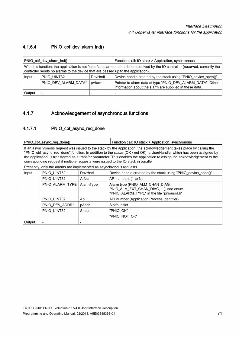
Interface Description 4.1 Upper layer interface functions for the application
ERTEC 200P PN IO Evaluation Kit V4.0 User Interface Description Programming and Operating Manual, 02/2013, A5E03855366-01 71
4.1.6.4 PNIO_cbf_dev_alarm_ind() PNIO_cbf_dev_alarm_ind() Function call: IO stack > Application, synchronous With this function, the application is notified of an alarm that has been received by the IO controller (reserved, currently the controller sends no alarms to the device that are passed up to the application). Input
PNIO_UINT32 DevHndl Device handle created by the stack using "PNIO_device_open()". PNIO_DEV_ALARM_DATA* pAlarm Pointer to alarm data of type "PNIO_DEV_ALARM_DATA". Other
information about the alarm are supplied in these data. Output - - -
4.1.7 Acknowledgement of asynchronous functions
4.1.7.1 PNIO_cbf_async_req_done PNIO_cbf_async_req_done() Function call: IO stack > Application, synchronous If an asynchronous request was issued to the stack by the application, the acknowledgement takes place by calling the "PNIO_cbf_async_req_done" function. In addition to the status (OK / not OK), a UserHandle, which has been assigned by the application, is transferred as a transfer parameter. This enables the application to assign the acknowledgement to the corresponding request if multiple requests were issued to the IO stack in parallel. Presently, only the alarms are implemented as asynchronous requests. Input
PNIO_UINT32 DevHndl Device handle created by the stack using "PNIO_device_open()". PNIO_UINT32 ArNum AR numbers (1 to N) PNIO_ALARM_TYPE AlarmType Alarm type (PNIO_ALM_CHAN_DIAG,
PNIO_ALM_EXT_CHAN_DIAG, ...), see enum "PNIO_ALARM_TYPE" in the file "pniousrd.h"
PNIO_UINT32 Api API number (Application Process Identifier) PNIO_DEV_ADDR* pAddr Slot/subslot PNIO_UINT32 Status "PNIO_OK"
"PNIO_NOT_OK" Output - -
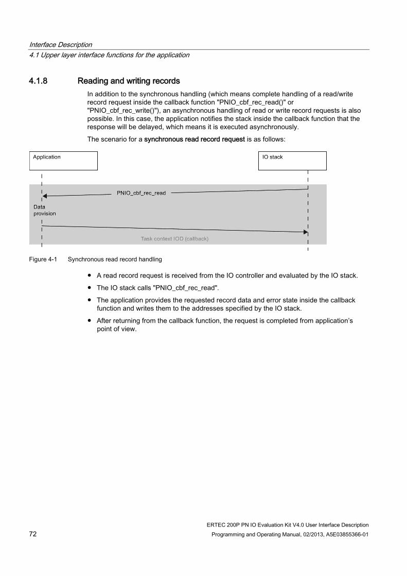
Interface Description 4.1 Upper layer interface functions for the application
ERTEC 200P PN IO Evaluation Kit V4.0 User Interface Description 72 Programming and Operating Manual, 02/2013, A5E03855366-01
4.1.8 Reading and writing records In addition to the synchronous handling (which means complete handling of a read/write record request inside the callback function "PNIO_cbf_rec_read()" or "PNIO_cbf_rec_write()"), an asynchronous handling of read or write record requests is also possible. In this case, the application notifies the stack inside the callback function that the response will be delayed, which means it is executed asynchronously.
The scenario for a synchronous read record request is as follows:
Figure 4-1 Synchronous read record handling
● A read record request is received from the IO controller and evaluated by the IO stack.
● The IO stack calls "PNIO_cbf_rec_read".
● The application provides the requested record data and error state inside the callback function and writes them to the addresses specified by the IO stack.
● After returning from the callback function, the request is completed from application’s point of view.
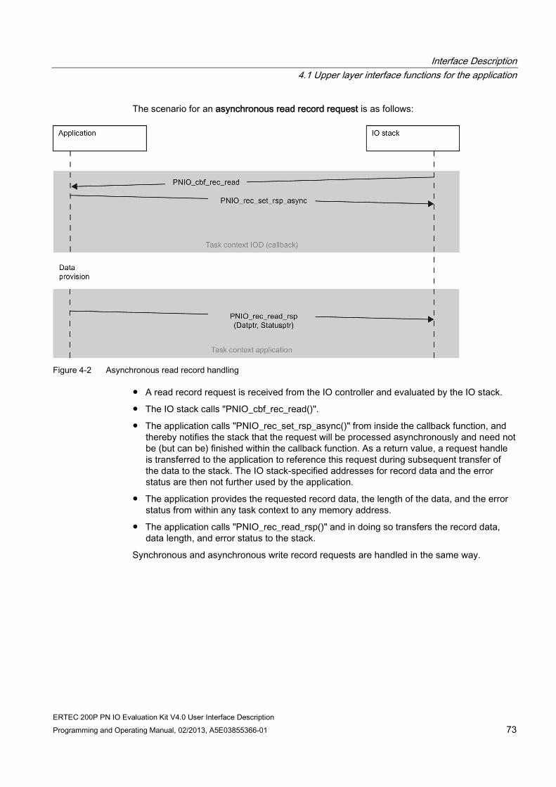
Interface Description 4.1 Upper layer interface functions for the application
ERTEC 200P PN IO Evaluation Kit V4.0 User Interface Description Programming and Operating Manual, 02/2013, A5E03855366-01 73
The scenario for an asynchronous read record request is as follows:
Figure 4-2 Asynchronous read record handling
● A read record request is received from the IO controller and evaluated by the IO stack.
● The IO stack calls "PNIO_cbf_rec_read()".
● The application calls "PNIO_rec_set_rsp_async()" from inside the callback function, and thereby notifies the stack that the request will be processed asynchronously and need not be (but can be) finished within the callback function. As a return value, a request handle is transferred to the application to reference this request during subsequent transfer of the data to the stack. The IO stack-specified addresses for record data and the error status are then not further used by the application.
● The application provides the requested record data, the length of the data, and the error status from within any task context to any memory address.
● The application calls "PNIO_rec_read_rsp()" and in doing so transfers the record data, data length, and error status to the stack.
Synchronous and asynchronous write record requests are handled in the same way.

Interface Description 4.1 Upper layer interface functions for the application
ERTEC 200P PN IO Evaluation Kit V4.0 User Interface Description 74 Programming and Operating Manual, 02/2013, A5E03855366-01
4.1.8.1 PNIO_cbf_rec_read PNIO_cbf_rec_read() Function call: IO stack > Application, synchronous This function is called by the IO stack if the IO controller has sent a read record data request to the device. A record is addressed by means of SlotNumber - SubslotNumber - Index. The application reads the requested data from the subslot and writes it to the address specified by "pBuf". The maximum permitted data length, in bytes, is transferred from the stack in "*pBufLen"; the actual transferred byte count is likewise reported back by the application in "*pBufLen". "PNIO_cbf_rec_read()" is called by the IO stack only for inserted submodules. Input
PNIO_UINT32 DevHndl Device handle created by the stack using "PNIO_device_open()". PNIO_UINT32 Api Application Process Identifier, specifies a profile PNIO_UINT16 ArNum AR number PNIO_UINT16 SessionKey Session Key PNIO_UINT32 SequenceNum Sequence number (gaps in the numbering are possible).
It can be used at the application level for handling multiple quasi-simultaneous requests.
PNIO_DEV_ADDR* pAddr Pointer to the insertion address (slot/subslot) of the submodule. "PNIO_ADDR_GEO" must be entered as the type.
PNIO_UINT32 RecordIndex Record index of the data to be read PNIO_UINT32* pBufLen (only for synchronous operation, has no use with asynchronous mode)
Pointer to the quantity of record data, in bytes. Here the stack transfers the maximum permitted record data length; the application returns the actual amount that was written. The maximum data length specified by the stack must not be exceeded under any circumstances.
PNIO_UINT8* pBuffer (only for synchronous operation, has no use with asynchronous mode) Pointer to where the application must copy the record data that has been read.
PNIO_ERR_STAT* pPnioState (only for synchronous operation, has no use with asynchronous mode) Pointer to 4-byte PNIO status, contains ErrCode, ErrDecode, ErrCode1, ErrCode2, AddValue 1, AddValue 2 per IEC 61158, see /2/
Output PNIO_UINT32 return Execution status: "PNIO_OK", "PNIO_NOT_OK"

Interface Description 4.1 Upper layer interface functions for the application
ERTEC 200P PN IO Evaluation Kit V4.0 User Interface Description Programming and Operating Manual, 02/2013, A5E03855366-01 75
4.1.8.2 PNIO_cbf_rec_write PNIO_cbf_rec_write() Function call: IO stack > Application, synchronous This function is called by the IO stack if the IO controller has sent a write record data request to the device. A record is addressed by means of SlotNumber - SubslotNumber - Index. The application accepts the record data starting from the address assigned with "pBuf". The data length in bytes is passed by the stack in "*pBufLen"; the actual transferred byte count is likewise reported back by the application in "*pBufLen". "PNIO_cbf_rec_write()" is called by the IO stack only for inserted submodules. Input
PNIO_UINT32 DevHndl Device handle created by the stack using "PNIO_device_open()". PNIO_UINT32 Api Application Process Identifier, specifies a profile PNIO_UINT16 ArNum AR number PNIO_UINT16 SessionKey Session Key PNIO_UINT32 SequenceNum Sequence number (gaps in the numbering are possible).
It can be used at the application level for handling multiple quasi-simultaneous requests.
PNIO_DEV_ADDR*
pAddr Pointer to the insertion address (slot/subslot) of the submodule. "PNIO_ADDR_GEO" must be entered as the type.
PNIO_UINT32 RecordIndex Record index of the data to be read PNIO_UINT32* pBufLen Pointer to the quantity of record data, in bytes. Here the stack transfers
the maximum permitted record data length. In synchronous mode the application returns the actual amount that was written. The maximum data length specified by the stack must not be exceeded under any circumstances.
PNIO_UINT8* pBuffer Pointer to the record data. PNIO_ERR_STAT* pPnioState (only for synchronous operation, don't care with asynchronous mode)
Pointer to 4-byte PNIO status, contains ErrCode, ErrDecode, ErrCode1, ErrCode2, AddValue 1, AddValue 2 per IEC 61158, see /2/
Output PNIO_UINT32 return Execution status: "PNIO_OK", "PNIO_NOT_OK"
4.1.8.3 PNIO_rec_set_rsp_async PNIO_rec_set_rsp_asnyc() Function call: Application > IO stack
(may be called only from "PNIO_cbf_rec_read" or "PNIO_cbf_rec_write") With this function, called from inside the callback functions "PNIO_cbf_rec_read()" or "PNIO_cbf_rec_write()", the application signals that the provision of the data will occur asynchronously. If "PNIO_rec_set_rsp_async()" is not called, the stack assumes synchronous processing; the interface is thus compatible with older versions of the development kit. Input - - Output PNIO_VOID* return Handle to reference the request later when data is transferred to the stack

Interface Description 4.1 Upper layer interface functions for the application
ERTEC 200P PN IO Evaluation Kit V4.0 User Interface Description 76 Programming and Operating Manual, 02/2013, A5E03855366-01
4.1.8.4 PNIO_rec_read_rsp PNIO_rec_read_rsp Function call: Application > IO stack In the case of asynchronous mode only, a read record request is completed using "PNIO_rec_read_rsp()". In doing so, the following is transferred to the stack: the data, the error state, and the length of the data actually read from the submodule. The function can be called from any user task. Input
PNIO_VOID* pRqHnd The handle for referencing the request was transferred to the application as a return value from the previous call of "PNIO_rec_set_rsp_async()".
PNIO_UINT8* pDat Pointer to the data provided by the application. In asynchronous mode the memory for the record data is provided by the application, and not (as in synchronous mode) by the IO stack.
PNIO_UINT32 NettoDatLength Length of the record data that was actually read from the submodule PNIO_ERR_STAT* pPnioState Pointer to the data provided; consists of 4-byte PNIO status (contains
ErrCode, ErrDecode, ErrCode1, ErrCode2) as well as 2 bytes each for AddValue 1 and AddValue 2 according to IEC 61158, see /2/. In asynchronous mode the memory for the error status data is provided by the application and not (as in synchronous mode) by the IO stack.
Output PNIO_UINT32 return Execution status: "PNIO_OK", "PNIO_NOT_OK"
4.1.8.5 PNIO_rec_write_rsp PNIO_rec_write_rsp Function call: Application > IO stack In the case of asynchronous mode, a write record request is completed using "PNIO_rec_write_rsp()". In doing so, the following is transferred to the stack: the error status and the length of the data actually written to the submodule. The function can be called from any user task. Input PNIO_VOID* pRqHnd The handle for referencing the request was transferred to the
application as a return value from the previous call of "PNIO_rec_set_rsp_async()".
PNIO_UINT32 NettoDatLength Length of the record data that was actually written to the submodule PNIO_ERR_STAT* pPnioState Pointer to the data provided; consists of 4-byte PNIO status (contains
ErrCode, ErrDecode, ErrCode1, ErrCode2) as well as 2 bytes each for AddValue 1 and AddValue 2 according to IEC 61158, see /2/. In asynchronous mode the memory for the error status data is provided by the application and not (as in synchronous mode) by the IO stack.
Output PNIO_UINT32 return Execution status: "PNIO_OK", "PNIO_NOT_OK"

Interface Description 4.1 Upper layer interface functions for the application
ERTEC 200P PN IO Evaluation Kit V4.0 User Interface Description Programming and Operating Manual, 02/2013, A5E03855366-01 77
4.1.9 Cyclic data exchange by means of the standard callback interface (SCI)
4.1.9.1 PNIO_initiate_data_read, PNIO_initiate_data_write PNIO_initiate_data_read() Function call: Application > IO Stack, synchronous This function performs one-time exchange of IO output data (data transfer direction: IO controller > device) between the IO stack and the application for all ARs (RT, IRT). The PN stack reserves a data buffer. The IO stack then calls the "PNIO_cbf_data_read()" function for all submodules with output data for which an active IO-AR to an IO controller exists. The application is therein requested to read the relevant IO output data from the IO stack and write it to the outputs of the submodule. The IO consumer status and IO provider status are also exchanged. "PNIO_initiate_data_read()" behaves synchronously, which means "PNIO_initiate_data_read()" does not return until after all "PNIO_cbf_data_read()" calls are called. The updated IO data are sent to the IO controller with the next transfer cycle. The user does not have to be concerned about buffer handling; the PN stack takes care of this. The user only has to implement the "PNIO_cbf_data_read()" function. A function body for this is located in the "iodapi_event.c" module.. Data consistency is ensured by locking mechanisms (max. 254 bytes consistent). Input PNIO_UINT32 DevHndl Device handle created by the stack using "PNIO_device_open()".
PNIO_UINT32* pApduStatus Pointer to 4-byte APDU status (see also PNIO specification /1b/). This contains: • Byte 0, 1: Cycle Counter (Big Endian format) • Byte 2: APDU status byte, see define
PNIO_APDU_STATUSBYTE_MASK • Byte 3: Transfer status
Output PNIO_UINT32 return Execution status: "PNIO_OK", "PNIO_NOT_OK"
PNIO_initiate_data_write() Function call: Application > IO Stack, synchronous This function performs one-time exchange of IO input data (data transfer direction: device > IO controller) between the IO stack and the application for all ARs (RT, IRT). The PN stack initially reserves a data buffer. The IO stack the calls the "PNIO_cbf_data_write()" function for all submodules with input data for which an active IO-AR to an IO controller exists. The application is therein requested to read the relevant IO input data from the submodule and write it to the buffer assigned by the IO stack. The IO consumer status and IO provider status are also exchanged. "PNIO_initiate_data_write()" behaves synchronously, which means "PNIO_initiate_data_write()" does not return until after all "PNIO_cbf_data_write()" calls are called. The user does not have to be concerned about buffer handling; the PN stack takes care of this. The user only has to implement the "PNIO_cbf_data_write()" function. A function body for this is located in the "iodapi_event.c" module. Data consistency is ensured by locking mechanisms (max. 254 bytes consistent). Input PNIO_UINT32 DevHndl Device handle created by the stack using "PNIO_device_open()". Output PNIO_UINT32 return Execution status: "PNIO_OK", "PNIO_NOT_OK"

Interface Description 4.1 Upper layer interface functions for the application
ERTEC 200P PN IO Evaluation Kit V4.0 User Interface Description 78 Programming and Operating Manual, 02/2013, A5E03855366-01
4.1.9.2 PNIO_cbf_data_write, PNIO_cbf_data_read PNIO_cbf_data_write() Function call: IO stack > Application, synchronous Reads in the physical input data from the submodule and writes it to the buffer specified by the IO stack. The function is called by the IO stack after the application has initiated a data communication with "PNIO_initiate_data_write()". The application must read the physical inputs of the submodule inserted in the slot/subslot and copy them to the buffer address specified by the stack. Caution: The length specified with "DataLen" must not be exceeded under any circumstances. The user is responsible for ensuring this. Input
PNIO_UINT32 DevHndl Device handle created by the stack using "PNIO_device_open()". PNIO_DEV_ADDR* pAddr Pointer to the insertion address (slot/subslot) of the submodule.
"PNIO_ADDR_GEO" must be entered as the type. PNIO_UINT32 BufLen Length of data, in bytes. PNIO_UINT8* pBuffer Pointer to data buffer to which the application must copy the IO input
data. The data length specified in "DataLen" must not be exceeded under any circumstances.
PNIO_IOXS Iocs Remote consumer status, was sent by the IO controller together with the output data. Currently defined in "iodapi.h": "PNIO_S_GOOD", "PNIO_S_BAD"; for more information see /1/ and /2/.
Output PNIO_IOXS Iops IO Provider Status. Currently defined in "iodapi.h": "PNIO_S_GOOD", "PNIO_S_BAD"; for more information see /1/ and /2/.
PNIO_cbf_data_read() Function call: IO stack > Application, synchronous Writes the IO output data to the physical outputs of the submodule. The function is called by the IO stack once the application has initiated a data communication with "PNIO_initiate_data_read()". The application must read the output data specified in "pData" and output it to the physical outputs of the specified submodule. The consumer status is reported back to the stack in the return value of the function. This consumer status is transmitted to the IO controller in the next cyclic RT message frame and can be evaluated there. Input
PNIO_UINT32 DevHndl Device handle created by the stack using "PNIO_device_open()". PNIO_DEV_ADDR* pAddr Pointer to the insertion address (slot/subslot) of the submodule.
"PNIO_ADDR_GEO" must be entered as the type. PNIO_UINT32 BufLen Length of data, in bytes. PNIO_UINT8* pBuffer Pointer to data buffer from which the application must read the IO
output data. PNIO_IOXS Iops Remote provider status, was sent by the IO controller together with
the output data. Currently defined in "iodapi.h": "PNIO_S_GOOD", "PNIO_S_BAD"; for more possible values see /1/ and /2/.
Output PNIO_IOXS Iocs IO Consumer Status. Currently defined in "iodapi.h": "PNIO_S_GOOD", "PNIO_S_BAD"; for more possible values see /1/ and /2/.

Interface Description 4.1 Upper layer interface functions for the application
ERTEC 200P PN IO Evaluation Kit V4.0 User Interface Description Programming and Operating Manual, 02/2013, A5E03855366-01 79
4.1.10 Cyclic data exchange by means of the optional DBA interface
4.1.10.1 Cyclic data exchange by means of the optional DBA interface Alternatively to the standard callback interface (SCI), IO data and provider/consumer status can also be exchanged via the Direct Buffer Access (DBA) interface. In this case, the complete IOCR data block, including IO data, IOPS and IOCS of the submodules, is provided to the application. The application extracts IO data, IOPS and IOCS for every submodule from this IOCR. An IOCR is either an input CR (device> IO controller) or output CR (IO controller > device).
The DBA interface includes the following functions:
PNIO_dbai_enter() Disables the call of PNIO_cbf functions and the write access to internal AR
management data, for example, when canceling AR PNIO_dbai_buf_lock() Requests an IOCR buffer (either input IOCR or output IOCR) PNIO_dbai_buf_unlock() Releases a previously allocated IOCR buffer after processing PNIO_dbai_exit() Releases the stack internal semaphore that was allocated with
"PNIO_dbai_enter()"
For calling "PNIO_dbai_buf_lock()" and for extraction of the IO data and IOPS/IOCS information from the IOCR, the application needs additional data that are transferred from the stack to the application in "PNIO_ar_info_ind()" and must be saved there. They are valid until the AR is terminated again.
The following data is transferred when "PNIO_dbai_buf_lock" is called:
● Pointer to the relevant IOCR (application may read from the IOCR pointer contained in "PNIO_cbf_ar_info_ind()", if it is protected with "PNIO_dbai_enter()"). Therefore, it need not retain a copy of this data.
● Transfer direction of the IOCR (input/output)
The following data is required to access the submodule-specific IO data and IOPS/IOCS of an input IOCR (data transfer direction device > IO controller):
● Slot number, subslot number of the configured input and output submodules
● IO data location (offset, length) of the configured input submodules
● Location (offset) of the (local) IOPS of the configured input modules
● Location (offset) of the (local) IOCS of the configured output modules
The following data is required to access the submodule-specific IO data and IOPS/IOCS of an output IOCR (data transfer direction IO controller > device):
● Slot number, subslot number of the configured input and output submodules
● IO data location (offset, length) of the configured output submodules
● Location (offset) of the (local) IOPS of the configured output modules
● Location (offset) of the (remote) IOCS of the configured input modules

Interface Description 4.1 Upper layer interface functions for the application
ERTEC 200P PN IO Evaluation Kit V4.0 User Interface Description 80 Programming and Operating Manual, 02/2013, A5E03855366-01
For a buffer access to an IOCR (input or output), the application must perform the following steps: PNIO_dbai_enter() Check whether the IOCR is still valid If valid PNIO_dbai_buf_lock() Process the buffer PNIO_dbai_buf_unlock() PNIO_dbai_exit()
4.1.10.2 PNIO_dbai_enter PNIO_dbai_enter() Function call: Application > IO Stack, synchronous This function must be called before "PNIO_dbai_buf_lock()", both to lock the calling of "PNIO_cbf_xxx" callback functions and to lock the modification of AR management data by the stack. This is necessary so that these data is not deleted due to a sudden termination of the AR while the application is still accessing them. By using this lock mechanism, the application can read directly from the pointers that are transferred with the AR Info indication which remain valid until the termination of the AR. Input - - - Output - - -
4.1.10.3 PNIO_dbai_exit PNIO_dbai_exit() Function call: Application > IO Stack, synchronous Releases the PNIO stack resources that were locked with "PNIO_dbai_enter()". This function must be called after the buffer has been released again with "dbai_buf_unlock()". Note: No "PNIO_cbf_xxx()" callback functions are called by the stack between "PNIO_dbai_enter" and "PNIO_dbai_exit". The buffer processing by the application should therefore be as brief as possible. Input - - - Output - - -

Interface Description 4.1 Upper layer interface functions for the application
ERTEC 200P PN IO Evaluation Kit V4.0 User Interface Description Programming and Operating Manual, 02/2013, A5E03855366-01 81
4.1.10.4 PNIO_dbai_buf_lock PNIO_dbai_buf_lock() Function call: Application > IO Stack, synchronous Requests an IOCR buffer from the PNIO stack. This buffer contains the current IO data, IOPS, and IOCS of the configured submodules. The data is transferred using a structure of type "PNIO_BUFFER_LOCK_TYPE". The application receives the input elements of this structure by means of "PNIO_cbf_ar_info_ind()". The pointer to the buffer and the cycle counter from the ADPU status are transferred as output parameters. This cycle counter can be used with IRT, for example, to determine the phase in which the IO data is actually transferred when the configured reduction ratio is greater than 1. Input PNIO_BUFFER_LOCK_TYPE* pLock Pointer to structure that contains:
• AR Handle • Session Key • Transfer direction ("PNIO_IOCR_TYPE_ENUM" IocrType) • Offset in the IOCR of the IO data to be locked (EB 200P only,
with length > 255 bytes, otherwise 0) • Length of the data to be locked (EB 200P: max. 254 bytes at a
time) • [out] pBuf pointer to the IOCR buffer • [out] APDU status, contains the cycle counter (bits 0 to 15)
Output PNIO_UINT32 return "PNIO_OK", "PNIO_NOT_OK"
4.1.10.5 PNIO_dbai_buf_unlock PNIO_dbai_buf_unlock() Function call: Application > IO Stack, synchronous With this function, a buffer that was requested with "PNIO_dbai_buf_lock()" is returned to the stack after processing by the application. Input PNIO_BUFFER_LOCK_TYPE* pLock Pointer to same data from "PNIO_dbai_buf_lock" Output PNIO_UINT32 return "PNIO_OK", "PNIO_NOT_OK"

Interface Description 4.1 Upper layer interface functions for the application
ERTEC 200P PN IO Evaluation Kit V4.0 User Interface Description 82 Programming and Operating Manual, 02/2013, A5E03855366-01
4.1.11 Receiving events and alarms
4.1.11.1 PNIO_cbf_ar_connect_ind PNIO_cbf_ar_connect_ind() Function call: IO stack > Application, synchronous The function signals the application that a new connection has been made to an IO controller. Input PNIO_UINT32 DevHndl Device handle created by the stack using "PNIO_device_open()".
PNIO_UINT32 HostIp IP address of the remote station (usually the IO controller) PNIO_UINT32 ArType See "cm_ar_type_enum" structure, possible values are:
• "CM_AR_TYPE_SINGLE" • "CM_AR_TYPE_SINGLE_RTC3" • "CM_AR_TYPE_SINGLE_SYSRED" (currently not implemented) • "CM_AR_TYPE_SUPERVISOR" (currently not implemented)
PNIO_UINT32 ArNum AR numbers (1 to N) Output - - -

Interface Description 4.1 Upper layer interface functions for the application
ERTEC 200P PN IO Evaluation Kit V4.0 User Interface Description Programming and Operating Manual, 02/2013, A5E03855366-01 83
4.1.11.2 PNIO_cbf_ar_ownership_ind PNIO_cbf_ar_ownership_ind() Function call: IO stack > Application, synchronous This function is used to inform the application of the specified configuration of the modules/submodules in the configuration. A data structure of type "PNIO_EXP" is passed for this. It contains a list of all configured submodules. The following is listed for each submodule: The slot (API/slot/subslot), the module and submodule ID, the IO properties (in, out, in-out) as well as the offsets for the input or output data of the submodule, and their provider and consumer states. Assumption of the ownership The submodules of the target configuration must be assigned before the data exchange with the AR, otherwise no valid data can be exchanged with this submodule via the AR. If the device application should NOT assume the AR ownership for a submodule (i.e. no valid IO data for this submodule should be exchanged), the OwnSessionKey element must be set to 0. Otherwise, which means when the application wants to exchange valid data for this submodule, OwnSessionKey must remain unchanged. Each subslot can be assigned a maximum of one AR, which means only one AR can assume ownership for a subslot when there are several ARs. For more ARs, this submodule is then marked as "superordinated locked". Verification of the target/actual configuration by application The application must also verify that the target configuration matches the actual configuration. If a wrong submodule is plugged into a slot/subslot (which means an incompatible submodule that therefore cannot be part of the data exchange), the element "IsWrongSubmod" = "PNIO_TRUE" must be set in the "PNIO_EXP_SUB" structure. If the correct submodule or a compatible replacement module has been plugged, however, the value of "IsWrongSubmod" remains unchanged (the default setting is "PNIO_FALSE"). Input PNIO_UINT32 DevHndl Device handle created by the stack using "PNIO_device_open()".
PNIO_UINT32 ArNum AR numbers (1 to N) PNIO_EXP* pOwnSub Pointer to data structure that contains a list of all configured
submodules and their properties (slot, data type, module/submodule ID, offsets of data and IOXS in the IOCR)
Output PNIO_VOID pOwnSub -> Sub[i]. OwnSessionKey
Session key unchanged: Ownership for submodule is assumed SessionKey = 0: Ownership declined
PNIO_VOID pOwnSub -> Sub[i]. IsWrongSubmod
= PNIO_TRUE when an incompatible submodule has been plugged, and therefore no data exchange is possible Leave unchanged (PNIO_FALSE) when the correct module (identical module/submodule ID) or a compatible replacement module has been plugged so that data exchange is possible.
4.1.11.3 PNIO_cbf_ar_indata_ind PNIO_cbf_ar_indata_ind() Function call: IO stack > Application, synchronous By means of an "AR-InData" indication, the stack notifies the application that the cyclic data communication was started, which means a first IO data frame was received from the IO controller after ApplicationReady. Input PNIO_UINT32 DevHndl Device handle created by the stack using "PNIO_device_open()".
PNIO_UINT16 ArNum Specifies the AR number; this number was transferred with "PNIO_cbf_ar_info_ind()" as an element of the "PNIO_AR_TYPE" structure.
PNIO_UINT16 SessionKey Session Key Output - - -

Interface Description 4.1 Upper layer interface functions for the application
ERTEC 200P PN IO Evaluation Kit V4.0 User Interface Description 84 Programming and Operating Manual, 02/2013, A5E03855366-01
4.1.11.4 PNIO_cbf_ar_disconn_ind PNIO_cbf_ar_disconn_ind() Function call: IO stack > Application, synchronous The stack notifies the application that a Disconnect event has occurred. An Disconnect event occurs if an existing connection is interrupted or explicitly terminated by the IO controller or device. Input
PNIO_UINT32 DevHndl Device handle created by the stack using "PNIO_device_open()". PNIO_UINT16 ArNum Specifies the AR number; this number was transferred with
"PNIO_cbf_ar_info_ind()" as an element of the "PNIO_AR_TYPE" structure.
PNIO_UINT16 SessionKey Session Key PNIO_AR_REASON ReasonCode Describes the reason for the termination of the application relation;
possible reason codes for a termination are located in the "iodapi.h" file, in the enum type definition "PNIO_AR_REASON{..}".
Output - - -
4.1.11.5 PNIO_cbf_param_end_ind PNIO_cbf_param_end_ind() Function call: IO stack > Application, synchronous The stack notifies the application that the parameter assignment of all modules has been completed. The application acknowledges this function by returning "PNIO_TRUE". This causes the "ApplicationReady" message to be automatically transmitted from the stack to the IO controller. In this case, "PNIO_async_appl_rdy()" may not be called by the application. However, if the application is not yet ready at this time, it can acknowledge with a return value of "PNIO_FALSE". It must then call the "PNIO_async_appl_rdy()" function itself at a later time. "PNIO_async_appl_rdy()" may and must only be called for the submodules for which the "PNIO_cbf_param_end_ind()" function has been completed with the return value "PNIO_SUBMOD_STATE_APPL_RDY_FOLLOWS". Input PNIO_UINT32 DevHndl Device handle created by the stack using "PNIO_device_open()".
PNIO_UINT16 ArNum Specifies the AR number; this number was transferred with "PNIO_cbf_ar_info_ind()" as an element of the "PNIO_AR_TYPE" structure.
PNIO_UINT16 SessionKey Session Key PNIO_UINT32 Api API number (only valid, when SubslotNum is not equal to 0) PNIO_UINT16 SlotNum Slot number (only valid, when SubslotNum is not equal to 0) PNIO_UINT16 SubslotNum • == 0: ParamEnd for all modules,
• <> 0: ParamEnd only for the specified module
PNIO_BOOL MoreFollows • "PNIO_TRUE": More "PNIO_cbf_param_end_ind()" calls for additional subslots follow
• "PNIO_FALSE": This is the last of all "PNIO_cbf_param_end_ind()" calls
Output PNIO_SUBMOD_STATE return • "PNIO_SUBMOD_STATE_RUN", if the submodule can supply valid data
• "PNIO_SUBMOD_STATE_STOP", if the submodule cannot supply valid data
• "PNIO_SUBMOD_STATE_APPL_RDY_FOLLOWS" if the submodule startup is not yet complete and this information is passed later to the stack by "PNIO_async_appl_rdy()".

Interface Description 4.1 Upper layer interface functions for the application
ERTEC 200P PN IO Evaluation Kit V4.0 User Interface Description Programming and Operating Manual, 02/2013, A5E03855366-01 85
4.1.12 Control functions
4.1.12.1 PNIO_set_dev_state PNIO_set_dev_state() Function call: Application > IO Stack, synchronous Sets the state of the device to "OPERATE/CLEAR". The function must be called once during startup to set the device to the "OPERATE" state. Input PNIO_UINT32 DevHndl Device handle created by the stack using "PNIO_device_open()".
PNIO_UINT32 DevState New status of the device. Possible values are • "PNIO_DEVSTAT_OPERATE" • "PNIO_DEVSTAT_CLEAR"
Output PNIO_UINT32 return • "PNIO_OK": Request was executed without problems
• "PNIO_NOT_OK": Error occurred during request execution

Interface Description 4.1 Upper layer interface functions for the application
ERTEC 200P PN IO Evaluation Kit V4.0 User Interface Description 86 Programming and Operating Manual, 02/2013, A5E03855366-01
4.1.13 Hardware comparators for isochronous mode
4.1.13.1 Hardware comparators for isochronous mode Functions have been implemented for isochronous mode (IRT), specifically for the handling of isochronous applications. These functions can control GPIO signals or call callback functions when events occur during the IO cycle.
Such events may include:
● A predetermined delay for the start of the cycle
● IO data transfer on the bus stopped (TRANS_END)
The configuration for this is stored in the so-called ISO objects. An ISO object contains the type of the event (time stamp/TRANS_END), the required parameters, such as delay time or callback function pointer, as well as ERTEC-internal resources required for the object (timers, multiplexers, ISRs, GPIOs).
A total of six different time marks and a TRANS_END event can be defined at a given time. Depending on the configuration of the times, ISRs and GPIOs, more than seven ISO objects can be activated in total by using multiple ERTEC-internal resources. The absolute number depends on the configuration.
Sequence context of the user callback function The callback functions of EVMA events are executed on the interrupt or system level of the operating system. They are set in the "ecos_bspadapt_ertec.c" file in the system adaptation. The functions "Bsp_EVMA_ISR()" and "Bsp_EVMA_DSR()" are implemented there for eCos. They have been installed as eCos ISR or DSR handlers for the corresponding EVMA events. When an EVMA interrupt event occurs, the operating system first calls the "Bsp_EVMA_ISR()" function. If the ISR is invoked with Return (CYC_ISR_HANDLED | CYG_ISR_CALL_DSR), "Bsp_EVMA_DSR()" is also executed. Otherwise, it is not.
The setting which determines whether the user callback function is executed in the ISR or DSR context, can be simply configured using
#define USER_CONTEXT_ISR 1 or #define USER_CONTEXT_ISR 0
Additional changes to "Bsp_EVMA_DSR" and "Bsp_EVMA_ISR" by the user are usually unnecessary.
Note
The callback functions should be as short as possible due to the high priority class. Keep in mind the permitted conditions of the operating system when running user code in the ISR or DSR state. In the DSR state, for example, no pending operating system service calls are permitted; in the ISR state absolutely no operating system service calls are permitted.
The EVMA functions are primarily intended for isochronous IRT functions, but they can also be used in RT mode if necessary.

Interface Description 4.1 Upper layer interface functions for the application
ERTEC 200P PN IO Evaluation Kit V4.0 User Interface Description Programming and Operating Manual, 02/2013, A5E03855366-01 87
4.1.13.2 PNIO_IsoActivateIsrObj PNIO_IsoActivateIsrObj() Function call: Application > IO Stack, synchronous Sets a comparator that invokes a callback function at a specified time. The point in time is a programmable delay time for the start of the cycle (NewCycle). Input PNIO_VOID
(PNIO_VOID*) pIsrCbf Callback function that is invoked at the time (NewCycle +
DelayTim_ns). The execution level (ISR or DSR) can be set in the system adaptation.
PNIO_UINT32 DelayTim_ns Specified delay time in ns for the start of the cycle (NewCycle). Permitted values are 0 ... send clock. A reduction ratio is ignored.
PNIO_ISO_OBJ_HNDL* pObjHnd The function returns a handle at the given address, which must be specified when deleting the object using "PNIO_IsoFreeObj()". If no ISO object can be created, "zero" is returned.
Output PNIO_UINT32 return • "PNIO_OK": Request was executed without problems
• "PNIO_NOT_OK": Error occurred during request execution
4.1.13.3 PNIO_IsoActivateGpioObj PNIO_IsoActivateGpioObj() Function call: Application > IO Stack, synchronous Sets a comparator, which outputs a pulse at a predetermined GPIO at a specified point in time. The point in time is a programmable delay time for the start of the cycle (NewCycle). The GPIO is set here to the data direction "output" in the function in addition to the corresponding alternate function (PNPLL_OUT). Input PNIO_UINT32 Gpio GPIO number on ERTEC.
GPIO 0 to 7 are permitted. PNIO_UINT32 DelayTim_ns Specified delay time in ns for the start of the cycle
(NewCycle). Permitted values are 0 ... send clock. Any configured reduction ratio is ignored.
PNIO_ISO_GPIO_LEVEL_TYPE GpioLevelType Specifies whether the output is high or low active. Permitted are "ISO_GPIO_LOW_ACTIVE", "ISO_GPIO_HIGH_ACTIVE".
PNIO_ISO_OBJ_HNDL* pObjHnd The function returns a handle at the given address, which must be specified when deleting the object using "PNIO_IsoFreeObj()". If no ISO object can be created, "zero" is returned.
Output PNIO_UINT32 return • "PNIO_OK": Request was executed without problems
• "PNIO_NOT_OK": Error occurred during request execution

Interface Description 4.1 Upper layer interface functions for the application
ERTEC 200P PN IO Evaluation Kit V4.0 User Interface Description 88 Programming and Operating Manual, 02/2013, A5E03855366-01
4.1.13.4 PNIO_IsoActivateTransEndObj PNIO_IsoActivateTransEndObj() Function call: Application > IO Stack, synchronous Sets a comparator that invokes a callback function after the transfer cycle has ended (TRANS_END event) on the bus. The point in time is a programmable delay time for the start of the cycle (NewCycle). Input PNIO_VOID
(PNIO_VOID*) pIsrCbf Callback function that is invoked at the time (NewCycle +
DelayTim_ns). The execution level (ISR or DSR) can be set in the system adaptation.
PNIO_ISO_OBJ_HNDL* pObjHnd The function returns a handle at the given address, which must be specified when deleting the object using "PNIO_IsoFreeObj()". If no ISO object can be created, "zero" is returned.
Output PNIO_UINT32 return • "PNIO_OK": Request was executed without problems
• "PNIO_NOT_OK": Error occurred during request execution
4.1.13.5 PNIO_IsoFreeObj PNIO_IsoFreeObj() Function call: Application > IO Stack, synchronous Delete a previously generated ISO object. Note: A GPIO configured with "PNIO_IsoActivateGpioObj()" is not reconfigured. If this GPIO is to be subsequently allocated to another function, (e.g. as GPIO input), the application must perform this switch itself using "Bsp_SetGpioMode". Input PNIO_ISO_OBJ_HNDL ObjHnd Object handle, which was previously created by
"PNIO_IsoActivatexxxxx()". Output PNIO_UINT32 return • "PNIO_OK":
Request was executed without problems • "PNIO_NOT_OK":
Error occurred during request execution

Interface Description 4.1 Upper layer interface functions for the application
ERTEC 200P PN IO Evaluation Kit V4.0 User Interface Description Programming and Operating Manual, 02/2013, A5E03855366-01 89
4.1.14 Error handling
4.1.14.1 PNIO_get_last_error PNIO_get_last_error() Function call: Application > IO Stack, synchronous Reads the last error that occurred when a "PNIO_xxxx()" function was called and that was signaled by CM in the response and makes it available to the application. Because most of the functions return only an aggregate error information (OK, NOT_OK), a detailed error information can be requested here, if required. If an error occurred, it is stored and kept until a new error occurs. A function call of "PNIO_xxxxx" that completed correctly and with "PNIO_OK" does not delete the stored error value, which means "PNIO_get_last_error" should only be called if the previous request was acknowledged with an error, that is a value other than PNIO_OK. Input - - - Output PNIO_ERR_ENUM return The possible values are stored in the enum type definition
"PNIO_ERR_ENUM" in the file "pnioerrx.h": • "PNIO_OK" • "PNIO_ERR_xxxxxx"
The definition "PNIO_ERR_ENUM" is located in the file "pnioerrx.h".

Interface Description 4.1 Upper layer interface functions for the application
ERTEC 200P PN IO Evaluation Kit V4.0 User Interface Description 90 Programming and Operating Manual, 02/2013, A5E03855366-01
4.1.14.2 PNIO_Log PNIO_Log() Function call: IO stack > Application, synchronous With this function, the stack notifies the application that an error or logging request has taken place. The error class (fatal error, error, logging, etc.) is communicated as well as a reference to the source file (Package ID, Module ID) and the line number in the code. The application can, for example, initiate error handling depending on the error class. Input PNIO_UINT32 DevHndl Device handle created by the stack using "PNIO_device_open()".
PNIO_UINT32 ErrLevel Designates the error class. The logging levels are subdivided into the following levels: • "PNIO_LOG_DEACTIVATED" • "PNIO_LOG_CHAT" • "PNIO_LOG_CHAT_HIGH" • "PNIO_LOG_NOTE" • "PNIO_LOG_NOTE_HIGH" • "PNIO_LOG_WARNING" • "PNIO_LOG_WARNING_HIGH" • "PNIO_LOG_ERROR" • "PNIO_LOG_ERROR_FATAL"
PNIO_UINT32 PackID Designates the packet in which the error occurred. Defined values are: • "PNIO_PACKID_ACP" • "PNIO_PACKID_BSPADAPT" • "PNIO_PACKID_CLRPC" • "PNIO_PACKID_CM" • "PNIO_PACKID_DCP" • "PNIO_PACKID_EDD" • "PNIO_PACKID_GSY" • "PNIO_PACKID_LLDP" • "PNIO_PACKID_LSAS" • "PNIO_PACKID_MRP" • "PNIO_PACKID_NARE" • "PNIO_PACKID_OHA" • "PNIO_PACKID_OS" • "PNIO_PACKID_PNPB" • "PNIO_PACKID_PNDV" • "PNIO_PACKID_POF" • "PNIO_PACKID_SOCK" • "PNIO_PACKID_TSKMA" • "PNIO_PACKID_OTHERS"
PNIO_UINT32 ModID Together with PackID, designates the module in which the error occurred. Module ID is unique within a packet.
PNIO_UINT32 LineNum Number of the line in which the error occurred. Output - - -

Interface Description 4.1 Upper layer interface functions for the application
ERTEC 200P PN IO Evaluation Kit V4.0 User Interface Description Programming and Operating Manual, 02/2013, A5E03855366-01 91
4.1.14.3 PNIO_set_iops PNIO_set_iops() Function call: Application > IO Stack, synchronous With this function, the application can optionally set the provider status (IOPS) for submodules that have no IO data and therefore for which an IOPS update as part of cyclic data exchange is not possible. This applies, for example, to the Ethernet interface and the Ethernet ports, which are modeled via subslot numbers >=0x8000. The set status is transferred to the controller with the next call of "PNIO_initiate_data_write" and is retained until it is overwritten by another call of "PNIO_set_iops". Input PNIO_UINT32 Api API number
PNIO_UINT32 SlotNum Slot number PNIO_UINT32 SubNum Subslot number PNIO_UINT8 lops IOPS value to be set ("PNIO_S_GOOD", "PNIO_S_BAD")
Output PNIO_UINT32 return "PNIO_OK," "PNIO_NOT_OK"
4.1.15 Other functions
4.1.15.1 PNIO_printf PNIO_printf() Function call: IO stack > Application, synchronous /
Application > Application, synchronous Central substitute for a "printf()" function. To allow forwarding of the variable parameters, they are converted into a format string and an argument list of type "va_list" and then passed to the lower-level and central output function "PNIO_print()". Input PNIO_INT8* fmt Format string, as in "printf"
... x, y, etc. Variable argument list as in "printf()" Output - - -
4.1.15.2 PNIO_TrcPrintf PNIO_TrcPrintf() Function call: IO stack > Application, synchronous /
Application > Application, synchronous Central output of messages to "PNIO_print()" or to a circular buffer for later analysis as ASCII characters. To allow them to be forwarded, variable parameters are converted into format string and an argument list of type "va_list" and then passed to the lower-level and central output function. The user can analyze the circular buffer in the debugger or can export it as desired using functions to be implemented by the user (e.g., via TCP/IP or similar). Input PNIO_INT8* fmt Format string, as in "printf"
... x, y, etc. Variable argument list as in "printf()" Output - - -

Interface Description 4.2 Lower layer interface functions for the Board Support Package
ERTEC 200P PN IO Evaluation Kit V4.0 User Interface Description 92 Programming and Operating Manual, 02/2013, A5E03855366-01
4.1.15.3 PNIO_get_version PNIO_get_version() Function call: Application > IO Stack, synchronous Read the version ID of the Development Package. Input PNIO_DK_VERSION* pVersion Pointer to a version ID of type "PNIO_VERSION". This function
copies the version to the specified address. Output PNIO_UINT32 return "PNIO_OK"
4.2 Lower layer interface functions for the Board Support Package
4.2.1 BSP functions for all platforms
4.2.1.1 Bsp_Init Bsp_Init() Function call: IO stack > BSP, synchronous "Init" function, called by the PNIO stack during startup before the tasks of the PNIO stack have started. The user may add any necessary initialization for the BSP adaptation interface here. Input - - - Output PNIO_UINT32 return "PNIO_OK"
4.2.1.2 Bsp_GetMacAddr Bsp_GetMacAddr() Function call: IO stack > BSP, synchronous Reads the local device MAC address of the IO controller Input PNIO_UINT8* pDevMacAddr Buffer for the MAC address with a length of 6 bytes. The function
subsequently writes the MAC address to the designated buffer. Output PNIO_UINT32 return "PNIO_OK", "PNIO_NOT_OK"
4.2.1.3 Bsp_GetPortMacAddr Bsp_GetPortMacAddr() Function call: IO stack > BSP, synchronous Reads the local port MAC address of the IO controller. In addition to the device MAC address, every port must have its own port MAC address in PROFINET. Input PNIO_UINT8* pPortMacAddr Buffer for the MAC address with a length of 6 bytes. The function
subsequently writes the MAC address to the designated buffer. PNIO_UINT32 PortNum Port number (1…N, N = number of ports) for which the port MAC
address should be read. Output PNIO_UINT32 return "PNIO_OK", "PNIO_NOT_OK"

Interface Description 4.2 Lower layer interface functions for the Board Support Package
ERTEC 200P PN IO Evaluation Kit V4.0 User Interface Description Programming and Operating Manual, 02/2013, A5E03855366-01 93
4.2.1.4 Bsp_EbSetLed (implementation optional) Bsp_EbSetLed() Function call: IO stack > BSP, synchronous Optional function for switching various LEDs on/off on the evaluation board. This function is not used in the PNIO stack, but only in the application example to indicate operational readiness and cyclic data communication. Input PNIO_LEDTYPE Led Specifies the LED number, see enum "PNIO_LEDTYPE" in the file
"bspadapt.h". PNIO_UINT32 Val 1: LED on, 0: LED off
Output PNIO_UINT32 return "PNIO_OK", "PNIO_NOT_OK"
4.2.2 Storage of non-volatile data The following data (non-volatile data types) must be stored on a PNIO device in non-volatile memory:
● Device name
● IP suite (IP address, subnet mask, default router address)
● Records of the physical device (PDEV) that have been transferred from the PNIO controller during the connection phase.
● I&M 1 to 4 (identification and maintenance data, see /1/)
These NV data types are read from non-volatile memory at the next startup and transferred to the PROFINET IO stack.
The following functions are available in the PROFINET user example for this:
Bsp_nv_data_clear() Resets all NV data types to factory setting Bsp_nv_data_store() Saves an NV data type to non-volatile memory Bsp_nv_data_restore() Reads an NV data type back from non-volatile memory Bsp_nv_data_memfree Releases the memory that was allocated by
Bsp_nv_data_restore
The functions named above are not used by the PROFINET stack itself, but only inside the application example for the handling of non-volatile data. Users can integrate the NV data interface into their own software as an example template and then redesign it in a completely different way.
4.2.2.1 Bsp_nv_data_clear Bsp_nv_data_clear() Function call: IO stack > BSP, synchronous This function is called from the customer application, if all non-volatile data types must be reset to the factory settings. This function may be directly called in the "PNIO_reset_factory_settings" function, for example, so that it is automatically executed when an engineering system requests a reset to factory settings. This function must be implemented by the user. Input - - - Output PNIO_UINT32 return "PNIO_OK", "PNIO_NOT_OK"
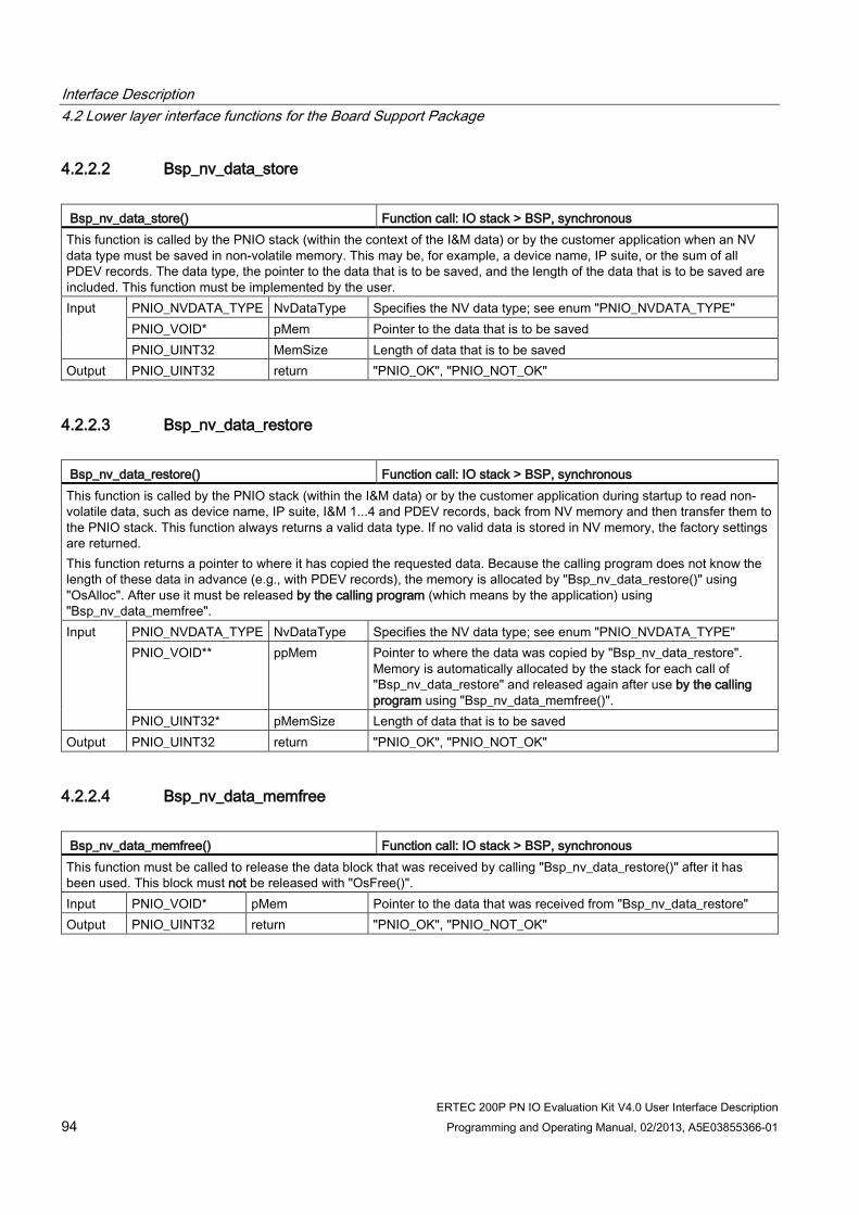
Interface Description 4.2 Lower layer interface functions for the Board Support Package
ERTEC 200P PN IO Evaluation Kit V4.0 User Interface Description 94 Programming and Operating Manual, 02/2013, A5E03855366-01
4.2.2.2 Bsp_nv_data_store Bsp_nv_data_store() Function call: IO stack > BSP, synchronous This function is called by the PNIO stack (within the context of the I&M data) or by the customer application when an NV data type must be saved in non-volatile memory. This may be, for example, a device name, IP suite, or the sum of all PDEV records. The data type, the pointer to the data that is to be saved, and the length of the data that is to be saved are included. This function must be implemented by the user. Input PNIO_NVDATA_TYPE NvDataType Specifies the NV data type; see enum "PNIO_NVDATA_TYPE"
PNIO_VOID* pMem Pointer to the data that is to be saved PNIO_UINT32 MemSize Length of data that is to be saved
Output PNIO_UINT32 return "PNIO_OK", "PNIO_NOT_OK"
4.2.2.3 Bsp_nv_data_restore Bsp_nv_data_restore() Function call: IO stack > BSP, synchronous This function is called by the PNIO stack (within the I&M data) or by the customer application during startup to read non-volatile data, such as device name, IP suite, I&M 1...4 and PDEV records, back from NV memory and then transfer them to the PNIO stack. This function always returns a valid data type. If no valid data is stored in NV memory, the factory settings are returned. This function returns a pointer to where it has copied the requested data. Because the calling program does not know the length of these data in advance (e.g., with PDEV records), the memory is allocated by "Bsp_nv_data_restore()" using "OsAlloc". After use it must be released by the calling program (which means by the application) using "Bsp_nv_data_memfree". Input PNIO_NVDATA_TYPE NvDataType Specifies the NV data type; see enum "PNIO_NVDATA_TYPE"
PNIO_VOID** ppMem Pointer to where the data was copied by "Bsp_nv_data_restore". Memory is automatically allocated by the stack for each call of "Bsp_nv_data_restore" and released again after use by the calling program using "Bsp_nv_data_memfree()".
PNIO_UINT32* pMemSize Length of data that is to be saved Output PNIO_UINT32 return "PNIO_OK", "PNIO_NOT_OK"
4.2.2.4 Bsp_nv_data_memfree Bsp_nv_data_memfree() Function call: IO stack > BSP, synchronous This function must be called to release the data block that was received by calling "Bsp_nv_data_restore()" after it has been used. This block must not be released with "OsFree()". Input PNIO_VOID* pMem Pointer to the data that was received from "Bsp_nv_data_restore" Output PNIO_UINT32 return "PNIO_OK", "PNIO_NOT_OK"
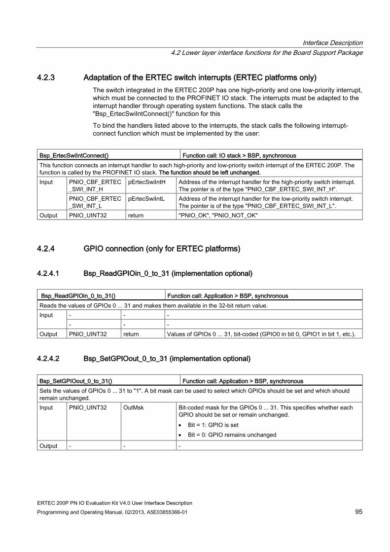
Interface Description 4.2 Lower layer interface functions for the Board Support Package
ERTEC 200P PN IO Evaluation Kit V4.0 User Interface Description Programming and Operating Manual, 02/2013, A5E03855366-01 95
4.2.3 Adaptation of the ERTEC switch interrupts (ERTEC platforms only) The switch integrated in the ERTEC 200P has one high-priority and one low-priority interrupt, which must be connected to the PROFINET IO stack. The interrupts must be adapted to the interrupt handler through operating system functions. The stack calls the "Bsp_ErtecSwiIntConnect()" function for this
To bind the handlers listed above to the interrupts, the stack calls the following interrupt-connect function which must be implemented by the user:
Bsp_ErtecSwiIntConnect() Function call: IO stack > BSP, synchronous This function connects an interrupt handler to each high-priority and low-priority switch interrupt of the ERTEC 200P. The function is called by the PROFINET IO stack. The function should be left unchanged. Input PNIO_CBF_ERTEC
_SWI_INT_H pErtecSwiIntH Address of the interrupt handler for the high-priority switch interrupt.
The pointer is of the type "PNIO_CBF_ERTEC_SWI_INT_H". PNIO_CBF_ERTEC_SWI_INT_L
pErtecSwiIntL Address of the interrupt handler for the low-priority switch interrupt. The pointer is of the type "PNIO_CBF_ERTEC_SWI_INT_L".
Output PNIO_UINT32 return "PNIO_OK", "PNIO_NOT_OK"
4.2.4 GPIO connection (only for ERTEC platforms)
4.2.4.1 Bsp_ReadGPIOin_0_to_31 (implementation optional) Bsp_ReadGPIOin_0_to_31() Function call: Application > BSP, synchronous Reads the values of GPIOs 0 ... 31 and makes them available in the 32-bit return value. Input - - -
- - - Output PNIO_UINT32 return Values of GPIOs 0 ... 31, bit-coded (GPIO0 in bit 0, GPIO1 in bit 1, etc.).
4.2.4.2 Bsp_SetGPIOout_0_to_31 (implementation optional) Bsp_SetGPIOout_0_to_31() Function call: Application > BSP, synchronous Sets the values of GPIOs 0 ... 31 to "1". A bit mask can be used to select which GPIOs should be set and which should remain unchanged. Input PNIO_UINT32 OutMsk Bit-coded mask for the GPIOs 0 ... 31. This specifies whether each
GPIO should be set or remain unchanged. • Bit = 1: GPIO is set • Bit = 0: GPIO remains unchanged
Output - - -
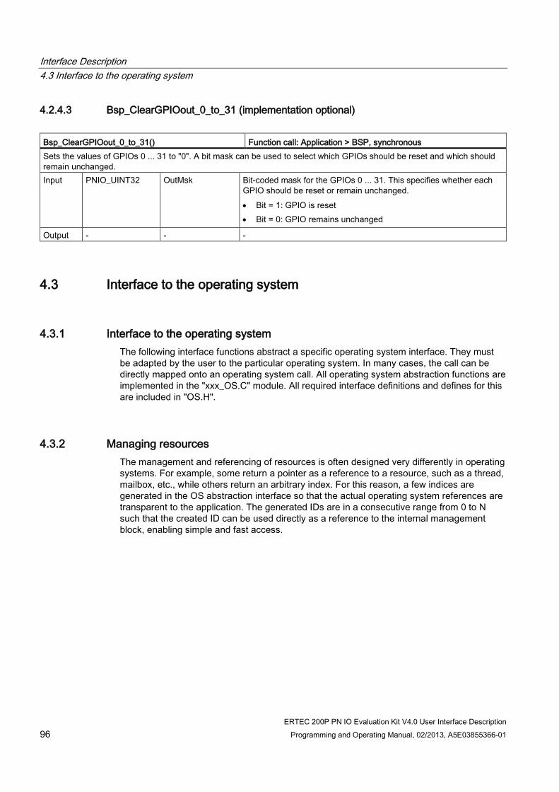
Interface Description 4.3 Interface to the operating system
ERTEC 200P PN IO Evaluation Kit V4.0 User Interface Description 96 Programming and Operating Manual, 02/2013, A5E03855366-01
4.2.4.3 Bsp_ClearGPIOout_0_to_31 (implementation optional) Bsp_ClearGPIOout_0_to_31() Function call: Application > BSP, synchronous Sets the values of GPIOs 0 ... 31 to "0". A bit mask can be used to select which GPIOs should be reset and which should remain unchanged. Input PNIO_UINT32 OutMsk Bit-coded mask for the GPIOs 0 ... 31. This specifies whether each
GPIO should be reset or remain unchanged. • Bit = 1: GPIO is reset • Bit = 0: GPIO remains unchanged
Output - - -
4.3 Interface to the operating system
4.3.1 Interface to the operating system The following interface functions abstract a specific operating system interface. They must be adapted by the user to the particular operating system. In many cases, the call can be directly mapped onto an operating system call. All operating system abstraction functions are implemented in the "xxx_OS.C" module. All required interface definitions and defines for this are included in "OS.H".
4.3.2 Managing resources The management and referencing of resources is often designed very differently in operating systems. For example, some return a pointer as a reference to a resource, such as a thread, mailbox, etc., while others return an arbitrary index. For this reason, a few indices are generated in the OS abstraction interface so that the actual operating system references are transparent to the application. The generated IDs are in a consecutive range from 0 to N such that the created ID can be used directly as a reference to the internal management block, enabling simple and fast access.

Interface Description 4.3 Interface to the operating system
ERTEC 200P PN IO Evaluation Kit V4.0 User Interface Description Programming and Operating Manual, 02/2013, A5E03855366-01 97
4.3.3 Description of the OS functions to be ported
4.3.3.1 OsInit() OsInit() Function call: IO stack > Operating system This function is called once during startup of the IO stack to initialize the operating system abstraction interface. "OsInit()" must finish before any of the other "Osxxx" functions are called. Input - - - Output PNIO_UINT32 return "PNIO_OK", "PNIO_NOT_OK"
4.3.3.2 OsAllocFX() OsAllocFX() Function call: IO stack > Operating system Allocation function for dynamic memory. The memory is not pre-assigned. Input PNIO_VOID** ppMem Pointer to which the address of the allocated memory is to be written
PNIO_UINT32 Length Length of the memory in bytes PNIO_UINT32 PoolID Various pools can be (optionally) specified for runtime optimization.
Possible defines are: • "MEMPOOL_DEFAULT" • "MEMPOOL_FAST" • "MEMPOOL_CACHED" • "MEMPOOL_UNCACHED" • "MEMPOOL_RX_TX_BUF" Note: All of the pools listed above may be cached in the system adaptation of the user example. "MEMPOOL_UNCACHED" and "MEMPOOL_RX_TX_BUF" are currently not used.
Output PNIO_UINT32 return "PNIO_OK", "PNIO_NOT_OK"
4.3.3.3 OsFreeX() OsFreeX() Function call: IO stack > Operating system Releases allocated memory. Here the same pool must be specified that was used for the allocation. Note: The "OsFree()" function is based on "OsFreeX()" and can be used without modification. Input PNIO_VOID* pMem Address of the allocated memory
PNIO_UINT32 PoolID Pool ID that was used during allocation Output PNIO_UINT32 return "LSA_OK", "LSA_NOT_OK"
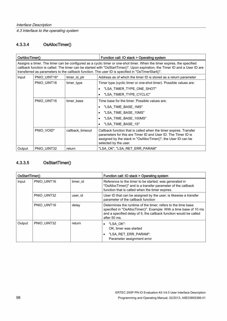
Interface Description 4.3 Interface to the operating system
ERTEC 200P PN IO Evaluation Kit V4.0 User Interface Description 98 Programming and Operating Manual, 02/2013, A5E03855366-01
4.3.3.4 OsAllocTimer() OsAllocTimer() Function call: IO stack > Operating system Assigns a timer. The timer can be configured as a cyclic timer or one-shot timer. When the timer expires, the specified callback function is called. The timer can be started with "OsStartTimer()". Upon expiration, the Timer ID and a User ID are transferred as parameters to the callback function. The user ID is specified in "OsTimerStart()". Input PNIO_UINT16* timer_id_ptr Address as of which the timer ID is stored as a return parameter
PNIO_UINT16 timer_type Timer type (cyclic timer or one-shot timer). Possible values are: • "LSA_TIMER_TYPE_ONE_SHOT" • "LSA_TIMER_TYPE_CYCLIC"
PNIO_UINT16 timer_base Time base for the timer. Possible values are: • "LSA_TIME_BASE_1MS" • "LSA_TIME_BASE_10MS" • "LSA_TIME_BASE_100MS" • "LSA_TIME_BASE_1S"
PNIO_VOID* callback_timeout Callback function that is called when the timer expires. Transfer parameters for this are Timer ID and User ID. The Timer ID is assigned by the stack in "OsAllocTimer()"; the User ID can be selected by the user.
Output PNIO_UINT32 return "LSA_OK", "LSA_RET_ERR_PARAM"
4.3.3.5 OsStartTimer() OsStartTimer() Function call: IO stack > Operating system Input PNIO_UINT16 timer_id Reference to the timer to be started; was generated in
"OsAllocTimer()" and is a transfer parameter of the callback function that is called when the timer expires.
PNIO_UINT32 user_id User ID that can be assigned by the user; is likewise a transfer parameter of the callback function
PNIO_UINT16 delay Determines the runtime of the timer; refers to the time base specified in "OsAllocTimer()". Example: With a time base of 10 ms and a specified delay of 5, the callback function would be called after 50 ms.
Output PNIO_UINT32 return • "LSA_OK": OK, timer was started
• "LSA_RET_ERR_PARAM": Parameter assignment error

Interface Description 4.3 Interface to the operating system
ERTEC 200P PN IO Evaluation Kit V4.0 User Interface Description Programming and Operating Manual, 02/2013, A5E03855366-01 99
4.3.3.6 OsStopTimer() OsStopTimer() Function call: IO stack > Operating system Stops a running timer. Input PNIO_UINT16 timer_id Reference to the timer Output PNIO_UINT32 return • "LSA_OK":
OK, timer was stopped • "LSA_RET_ERR_PARAM":
Parameter assignment error
4.3.3.7 OsFreeTimer() OsFreeTimer() Function call: IO stack > Operating system Releases a timer that was allocated with "OsAllocTimer". Input PNIO_UINT16 timer_id Reference to the timer Output PNIO_UINT32 return "LSA_OK", "LSA_RET_ERR_TIMER_IS_RUNNING"
4.3.3.8 OsEnterX() OsEnterX() Function call: IO stack > Operating system Assigns a mutex. A maximum of "MAXNUM_OF_NAMED_MUTEXES" can be assigned, which are managed by "xxx_os.c". Input PNIO_UINT32 MutexId Identifier for the mutex. Possible values are:
• 0…. (MAXNUM_OF_NAMED_MUTEXES - 1)
Output - -
4.3.3.9 OsExitX OsExit() Function call: IO stack > Operating system Releases an assigned mutex. Input PNIO_UINT32 MutexId Identifier for the mutex. Possible values are:
• 0…. (MAXNUM_OF_NAMED_MUTEXES - 1)
Output - - -

Interface Description 4.3 Interface to the operating system
ERTEC 200P PN IO Evaluation Kit V4.0 User Interface Description 100 Programming and Operating Manual, 02/2013, A5E03855366-01
4.3.3.10 OsEnterShort OsEnterShort() Function call: IO stack > Operating system Note: Not used on ERTEC platforms; only exists for Soft_EDD. Input - - - Output - - -
4.3.3.11 OsExitShort OsExitShort() Function call: IO stack > Operating system Note: Not used on ERTEC platforms; only exists for Soft_EDD. Input - - - Output - - -
4.3.3.12 OsAllocSemB OsAllocSemB() Function call: IO stack > Operating system Generates a binary semaphore. The semaphore must be empty in its initial state. Input PNIO_UINT32* pSemId Pointer as of which the semaphore ID is returned. Output PNIO_UINT32 return "PNIO_OK", "PNIO_NOT_OK"
4.3.3.13 OsFreeSemB OsFreeSemB() Function call: IO stack > Operating system Deletes a semaphore that was previously created with "OsAllocSemB()". Input PNIO_UINT32 SemId Semaphore ID that was created by "OsAllocSemB()". Output PNIO_UINT32 return "PNIO_OK", "PNIO_NOT_OK"
4.3.3.14 OsTakeSemB OsTakeSemB() Function call: IO stack > Operating system Occupies a binary semaphore. If the semaphore has already been occupied, the function is blocking. Input PNIO_UINT32 SemId Semaphore ID that was created by "OsAllocSemB()". Output PNIO_UINT32 return "PNIO_OK", "PNIO_NOT_OK"

Interface Description 4.3 Interface to the operating system
ERTEC 200P PN IO Evaluation Kit V4.0 User Interface Description Programming and Operating Manual, 02/2013, A5E03855366-01 101
4.3.3.15 OsGiveSemB OsGiveSemB() Function call: IO stack > Operating system Releases a semaphore that was occupied "OsTakeSemB()". Input PNIO_UINT32 SemId Semaphore ID that was created by "OsAllocSemB()". Output PNIO_UINT32 return "PNIO_OK", "PNIO_NOT_OK"
4.3.3.16 OsSetThreadPrio OsSetThreadPrio() Function call: IO stack > Operating system Note:Not used on ERTEC platforms; only exists for Soft_EDD. Changes the task priority. This causes the thread priority of the EDD low context thread to be temporarily increased in the IO stack to prevent it from being interrupted by the EDD high context thread. "OsSetThreadPrio" is used for this purpose in the output macros "EDD_ENTER_HIGH" and "EDD_EXIT_HIGH". The priority of the task is temporarily increased there to "TASK_PRIO_HIGHEST". Input PNIO_UINT32 ThreadId ID of the thread, the priority of which is to be changed.
PNIO_UINT32 NewThreadPrio New priority value to be set Output PNIO_UINT32 return "LSA_OK", "LSA_NOT_OK"
Note
Synchronization of the EDD high thread and EDD low thread is provided via "OsSetThreadPrio()" so that the EDD low context cannot be interrupted by the EDD high context. The high thread, on the other hand, cannot be interrupted by the low thread because of its higher start priority.
4.3.3.17 OsCreateThread OsCreateThread() Function call: IO stack > Operating system Creates a thread (task). All tasks run in the same address space. Input PNIO_VOID* pThreadEntry Entry address for the task.
PNIO_UINT8* pThreadName Specification of a name for the thread. This name is intended for debugging purposes only and can be omitted if the operating system does not support debugging.
PNIO_UINT32 ThreadPrio Priority of task. Note: The priorities of the tasks of the IO stack are set in the "os_cfg.h" file.
PNIO_UINT32* pThreadId The address of the returned thread ID is specified here. Output PNIO_UINT32 return "LSA_OK", "LSA_NOT_OK"

Interface Description 4.3 Interface to the operating system
ERTEC 200P PN IO Evaluation Kit V4.0 User Interface Description 102 Programming and Operating Manual, 02/2013, A5E03855366-01
4.3.3.18 OsStartThread OsStartThread() Function call: IO stack > Operating system Starts the thread created with "OsCreateThread()". Note: For some operating systems, the thread is automatically started with the Create call; in others, an additional start call is required. For standardization, the model used here provides an extra start call. If, for example, the operating system starts the task automatically, the task can be held in a waiting state using a Wait flag until "OsStartThread()" is executed. Input PNIO_UINT32 ThreadId Thread ID; was transferred as a return parameter in
"OsCreateThread()" Output PNIO_UINT32 return "LSA_OK", "LSA_NOT_OK"
4.3.3.19 OsWaitOnEnable() OsWaitOnEnable() Function call: IO stack > Operating system This function enables a created task to be kept in a waiting state until an "OsStartThread()" is executed. "OsWaitOnEnable()" should thus be executed as the first call in a created task. Input - - - Output PNIO_UINT32 return "LSA_OK", "LSA_NOT_OK"
4.3.3.20 OsGetThreadId() OsGetThreadId() Function call: IO stack > Operating system Reads the Thread ID for the current task. It does not directly return the Thread ID that was provided by the operating system, but rather a reference (table index) that is generated by the OS package. For tasks the are unknown to the OS, the value of "TskIdPost" is returned. Note: In the context of the LSA timer, "OsGetThreadId()" can also be called by system tasks or ISRs, depending on the implementation of the OS timer functions. In such cases, no thread ID would have been assigned by the OS, because system tasks or ISRs are certainly not created with "OsCreateThread". For users, this simply means that they have to return the thread ID of the post thread (TskIdPost) as a dummy thread ID. Input - - - Output PNIO_UINT32 return Thread ID of the current task. For unknown threads, which means
threads that were not created with "OsCreateThread()", the value of "TskIdPost" must be returned.

Interface Description 4.3 Interface to the operating system
ERTEC 200P PN IO Evaluation Kit V4.0 User Interface Description Programming and Operating Manual, 02/2013, A5E03855366-01 103
4.3.3.21 OsCreateMsgQueue() OsCreateMsgQueue() Function call: IO stack > Operating system Creates a message queue. Here a message queue is always permanently assigned to a thread. At most one message queue may be assigned to a thread. Each message contains 2 pointers as data. Thus, for a pointer width of 4 bytes, a message is 8 bytes in length. The reason for this is that the "OsCreateMsgQueue" function in the system adaptation of the IO stack is frequently used to call a function in a different thread context. Example: To call the "fx (pData)" function in the thread context "Thread_1", "OsSendMessageX (Thread_1, fx, pdata, OS_MBX_PRIO_NORM)" is called. Input PNIO_UINT32 ThreadId ID of the thread to which the message queue is to be assigned. Output PNIO_UINT32 return • "LSA_OK":
Message queue could be assigned • "LSA_NOT_OK":
Error occurred.
4.3.3.22 OsWait_ms() OsWait_ms() Function call: IO stack > Operating system Waits a specified time. Input PNIO_UINT32 PauseTime_ms Wait time in milliseconds. Output - - -
4.3.3.23 OsGetTime_us() OsGetTime_us() Function call: IO stack > Operating system Reads the current time, in microseconds, since the last system start. Input - - - Output PNIO_UINT32 return Current time in microseconds.
4.3.3.24 OsGetUnixTime() OsGetUnixTime() Function call: IO stack > Operating system Reads the current time, in seconds. The number of seconds since the system start are indicated here. Input - - - Output PNIO_UINT32 return Current time in seconds.

Interface Description 4.3 Interface to the operating system
ERTEC 200P PN IO Evaluation Kit V4.0 User Interface Description 104 Programming and Operating Manual, 02/2013, A5E03855366-01
4.3.3.25 OsReadMessageBlocked() OsReadMessageBlocked() Function call: IO stack > Operating system This function performs blocked reading of a 4-byte long message for the specified thread that was sent by "OsSendMessage()". The message contains one pointer. The thread ID is required as management information to optimize performance during operation. Thus, every thread should read its Thread ID once with "OsGetThreadId()" and remember it. Note: As of version 3.0.0 of the development kit, the time critical communication internal to the stack has been converted from 8-byte to 4-byte messages. This was also done to set up in a time-optimized manner on operating systems that only support 4-byte messages instead of 8-byte messages. Input PNIO_VOID** ppMessage PtrPtr to the message
PNIO_UINT32 ThreadId ID of the receiving thread (and thus this thread's own ID) Output PNIO_UINT32 return "LSA_OK", "LSA_NOT_OK"
4.3.3.26 OsReadMessageBlockedX() OsReadMessageBlockedX() Function call: IO stack > Operating system This function performs blocked reading of a 8-byte long message for the specified thread that was sent by "OsSendMessageX()". The message always contains 2 pointers. The thread ID is required as management information to optimize performance during operation. Thus, every thread should read its Thread ID once with "OsGetThreadId()" and remember it. Input PNIO_VOID** ppMessage1 PtrPtr to Message1
PNIO_VOID** ppMessage2 PtrPtr to Message2 PNIO_UINT32 ThreadId ID of the receiving thread (and thus this thread's own ID)
Output PNIO_UINT32 return "LSA_OK", "LSA_NOT_OK"
4.3.3.27 OsSendMessage() OsSendMessage() Function call: IO stack > Operating system This function sends a message with only one pointer (instead of two). On the receiving end, the message is received with "OsReadMessageBlocked()". Input PNIO_UINT32 ThreadId ID of the receiver thread
PNIO_VOID* pMessage Pointer to the actual message PNIO_UINT32 MsgPrio A priority can be assigned to the message. Within the system
implementation of the PNIO thread, all messages have the same priority. However, the parameter can be used in the context of adapting the IO stack to a specific platform if it is advantageous to do so.
Output PNIO_UINT32 return "LSA_OK", "LSA_NOT_OK"

Interface Description 4.3 Interface to the operating system
ERTEC 200P PN IO Evaluation Kit V4.0 User Interface Description Programming and Operating Manual, 02/2013, A5E03855366-01 105
4.3.3.28 OsSendMessageX() OsSendMessageX() Function call: IO stack > Operating system An extended "OsSendMessage" function: Sends a message with 2 pointers. On the receiving end, the message is received with "OsReadMessageBlockedX()". This enables 2 separate messages to be transmitted with a single "OsSendMessageX()" call. For the rationale, see the description of the "OsCreateMsgQueue()" function. Input PNIO_UINT32 ThreadId ID of the receiver thread
PNIO_VOID* pMessage1 Pointer to actual message 1 PNIO_VOID* pMessage2 Pointer to actual message 2 PNIO_UINT32 MsgPrio A priority can be assigned to the message. Within the system
implementation of the PNIO thread, all messages have the same priority. However, the parameter can be used in the context of adapting the IO stack to a specific platform if it is advantageous to do so.
Output PNIO_UINT32 return "LSA_OK", "LSA_NOT_OK"
4.3.3.29 __InterlockedDecrement() __InterlockedDecrement() Function call: IO stack > Operating system Decrement a long value under interrupt lock. Input PNIO_INT32 pVal Address of the value to decrement Output PNIO_INT32* pVal The value from the specified address is decremented.
PNIO_INT32 return In addition, the result ("*pVal") is also sent as a return value.
4.3.3.30 __InterlockedIncrement() __InterlockedIncrement() Function call: IO stack > Operating system Increment a long value under interrupt lock. Input PNIO_INT32 pVal Address of the value to increment Output PNIO_INT32* pVal The value from the specified address is incremented.
PNIO_INT32 return In addition, the result ("*pVal") is also sent as a return value.
4.3.3.31 OsIntDisable() OsIntDisable() Function call: IO stack > Operating system Locks the interrupts of the system. Input - - - Output - - -

Interface Description 4.3 Interface to the operating system
ERTEC 200P PN IO Evaluation Kit V4.0 User Interface Description 106 Programming and Operating Manual, 02/2013, A5E03855366-01
4.3.3.32 OsIntEnable() OsIntEnable() Function call: IO stack > Operating system Releases the interrupts of the system. Input - - - Output - - -
4.3.4 Encapsulation of standard library function calls In order to achieve the greatest possible degree of platform independence, no standard library functions are directly called in the PNIO stack. Instead, they are accessed via the OS abstraction interface. Consequently, the associated standard library header files should only be included in a few of the modules of the Development Package.
Calls of the abstraction interface are generally routed unchanged to the standard library so that a detailed description of these functions is not necessary.
The following functions of the OS interface were defined for this purpose:
● OsAtoi
● OsHtons, OsHtonl
● OsNtohs, OsNtohl
● OsMemCpy
● OsMemMove
● OsMemSet
● OsMemCmp
● OsStrCmp
● OsStrnCmp
● OsStrCpy
● OsStrnCpy
● OsStrChr
● OsStrLen
● OsRand
● OsSrand
The functions listed above can as a rule be used without modification, because they are supported in the same way by almost all platforms.
Additional functions not listed here, that are contained in "xx_OS.C", can likewise be used without modification because they do not directly access operating system functions. Thus, for example, "OsAlloc()" is redirected to "OsAllocX()" with "PoolId=DEFAULT" and does not have be adapted.

Interface Description 4.4 Important notes and limitations
ERTEC 200P PN IO Evaluation Kit V4.0 User Interface Description Programming and Operating Manual, 02/2013, A5E03855366-01 107
4.3.5 OS functions called by the application example In order to achieve the greatest possible degree of platform independence, platform-specific calls by the application example were also integrated into the OS abstraction layer "xx_os.c" ("xx" stands for the platform name).
The functions described in this section are not called by the PROFINET IO stack itself, but rather only by the application example.
● "OsGetChar" reads an ASCII character from the standard console
● "OsKeyScan32" reads a 32-bit numeric value from the standard console
● "OsReboot" performs a system restart
4.4 Important notes and limitations
4.4.1 Number of IO devices The present implementation of the system adaptation allows only one device instance. Multidevice functionality is not implemented in the system adaptation.
4.4.2 Number of modules and submodules The total number of modules and submodules and the maximum values for slot and subslot numbers are defined in the "iod_cfg2.h" file in the "sysadapt1\cfg" subdirectory.
Gaps are permitted in the sequence of slot numbers and subslot numbers. Thus, the full specification as defined in the value range of the PNIO slot and subslot numbers is usable whereas the maximum number of submodules is limited.
4.4.3 Maximum amount of user data for a device The maximum amount of process data is determined by the maximum frame size (1440 bytes net) and the number of physical subslots with input or output data (a parameter in the GSD file). The maximum data length in bytes is:
● Maximum number of input bytes = MaxInputLength - 4 - (number of input subslots) – (number of output subslots)
● Maximum number of output bytes = MaxOutputLength - 4 - (number of input subslots) – (number of output subslots)
A submodule containing both input and output data is therefore counted as both an input subslot as well as an output subslot.
"MaxInputLength" and "MaxOutputLength" are attributes in the GSD file. Both values should be set to 1440 bytes for ERTEC 200P.

Interface Description 4.4 Important notes and limitations
ERTEC 200P PN IO Evaluation Kit V4.0 User Interface Description 108 Programming and Operating Manual, 02/2013, A5E03855366-01
4.4.4 Functional limitations The following functions are not included in the current version or have not yet been tested:
● Takeover of modules by a supervisor
● Multicast communication
● RT over UDP
● Shared input

ERTEC 200P PN IO Evaluation Kit V4.0 User Interface Description Programming and Operating Manual, 02/2013, A5E03855366-01 109
Appendix A A.1 Abbreviations / Glossary of terms
ACP Acyclic Communication Protocol, refers to one of the basic software packages of
the IO stack API Application Process Identifier AR Application Relationship BSP Board Support Package CLRPC Connectionless Remote Procedure Call, refers to one of the basic software
packages of the IO stack CM Context Management, refers to one of the basic software packages of the IO
stack DAP Device Access Point, specific entry in the GSD file DBAI Direct Buffer Access Interface DCP Discovery and basic Configuration Protocol, refers to one of the basic software
packages of the IO stack DK_SW Development Kit Software (development kit for platforms based on standard
Ethernet controllers) EB 200P Evaluation Board for ERTEC 200P (component of the Evaluation Kit
ERTEC 200P) EDDI Ethernet Device Driver for IRTE switch in the ERTEC 200/400 (earlier versions:
EDD_ERTEC) EDDP Ethernet Device Driver for PN switch in the ERTEC 200P EDDS Ethernet Device Driver for Standard Ethernet controller (earlier versions:
EDD_soft) EDD Ethernet Device Driver, general term for EDDI, EDDP, EDDS ELOG Error Logging for debugging purposes (level 1 = only errors are output) GSD Generic Station Description GSDML GSD Markup Language GSY Generic Sync module, refers to one of the basic software packages of the IO
stack IOCR Input/Output Communication Relationship IOCS Input/Output Object Consumer Status IOPS Input/OutputObject Provider Status IRT Isochronous RealTime, Class 2 (IRT Class 2) or Class 3 (IRT Class 3) LLDP Link Layer Discovery Protocol (IEEE 802.1AB, allows stations to exchange
chassis and port information) LSA Layer Structure Architecture LW Drive

Appendix A.1 Abbreviations / Glossary of terms
ERTEC 200P PN IO Evaluation Kit V4.0 User Interface Description 110 Programming and Operating Manual, 02/2013, A5E03855366-01
MIB Management Information Base. Database for SNMP services MRP Media Redundancy Protocol NARE Name Address Resolution NRT Non Realtime is a generic term for all non-real-time frames (not type 0x8892) NV Non-volatile OHA Object Handler OS Operating System, refers here to the abstraction layer for any operating system
to which the IO stack is to be ported. PDEV Physical Device PNIO PROFINET IO PNO PROFIBUS Nutzer Organisation (user organization) PCF Polymeric Cladded Fiber (optical communication medium) POF Polymeric Optical Fiber (optical communication medium) RT Real Time is a generic term for acyclic and cyclic real-time RT Class RealTime class according to the PROFINET IO specification SI Standard Interface SNMP Simple Network Management Protocol SOCK UDP Socket Interface for PROFINET IO, refers to one of the basic software
packages of the IO stack TAP Test Access Port UDP User Datagram Protocol UUID Universal Unique Identifier

Appendix A.2 References
ERTEC 200P PN IO Evaluation Kit V4.0 User Interface Description Programming and Operating Manual, 02/2013, A5E03855366-01 111
A.2 References /1a/ PROFINET IO Specification IEC 61158 – part5
PROFINET IO Application Layer Service Specification
(Can be downloaded from the PNO website (http://www.profibus.com))
/1b/ PROFINET IO Specification IEC 61158 – part6
PROFINET IO Application Layer Protocol Specification
(Can be downloaded from the PNO website (http://www.profibus.com))
/2/ GSDML Specification for PROFINET IO
Version 2.3, Order No: 2.352
PROFIBUS User Organization e.V.
(Can be downloaded from the PNO website (http://www.profibus.com))
/3/ Industrial Communication with PROFINET
Manfred Popp
PROFIBUS User Organization e.V.
Order number 4.182
/4/ PROFINET Technology and Application
System Description
(Can be downloaded from the PNO website (http://www.profibus.com))

Appendix A.2 References
ERTEC 200P PN IO Evaluation Kit V4.0 User Interface Description 112 Programming and Operating Manual, 02/2013, A5E03855366-01


![INVITATION_TO_LOVE_2005 200p 21.1.2011[1]](https://img.pdfslide.net/doc/110x75/577d2ecb1a28ab4e1eb00199/invitationtolove2005-200p-21120111.jpg)