Embed Size (px)
Citation preview
ES 1050 – INTRODUCTORY DESIGN AND INNOVATION STUDIO MANUAL, PART 1, FALL SEMESTER, 2014
1
Western University Faculty of Engineering
Engineering Science 1050
Course Manual
Introductory Engineering Design and Innovation Studio
Part 1, Fall Semester, 2014
The contents of this document are subject to updates. All efforts have been made to ensure that this document is correct and in accord with the policies of the University of Western Ontario (UWO) and the UWO Faculty of Engineering. Any changes to this document will be posted on the ES 1050 course website (owl.uwo.ca). Students are responsible for checking the website; if there are any discrepancies the web site is considered correct
ES 1050 – INTRODUCTORY DESIGN AND INNOVATION STUDIO MANUAL, PART 1, FALL SEMESTER, 2014
2
Table of Contents
Chapter 1. Course objectives, knowledge and skills gained
1.1 Learning objectives
1.2 Knowledge and skills participants should gain
Chapter 2. Course key components
2.1 Main lecture topics
2.2 Studio Sections
2.3 The Design Notebook
2.4 Design Project I – Creativity
2.4.1 Goal of the Creativity project, deliverables and evaluation
2.4.2 Problem definition and concept list
2.4.3 Design sketch of a concept
2.4.4 Prototype and design presentation
2.4.5 Final design report
2.4.6 Design team grade distribution criteria
2.4.7 Grade distribution form for design team
2.5 Design Project II – Iteration
2.5.1 Goal of the project and constrains
2.5.2 Deliverables and evaluation
2.5.3 Critique form
2.5.4 Final design report
2.6 Interview assignment
2.7 Graphics Assignment
2.8 Mark Breakdown, Fall Semester 2014
Chapter 3. Examples
3.1 Design notebook
3.2 Interview assignment
3.3 Design Project I report
3.4 Design Project II report
3.5 Grade Distribution
Chapter 4. Course necessary tools
4.1 SolidWorks
4.2 Excel
4.3 Matlab
4.4 Manufacturing and Student Shop Resources
ES 1050 – INTRODUCTORY DESIGN AND INNOVATION STUDIO MANUAL, PART 1, FALL SEMESTER, 2014
3
Chapter 1
Course Objectives, Knowledge and Skills Gained
1.1 Course objectives.
This course is an introduction to the principles and practices of professional
engineering design. The ultimate goal of the ES 1050 course is to give students a
broad introduction to engineering and to educate them about the engineering
profession. The course exposes students to engineering disciplines and tools
through the design projects for the purpose of providing initial knowledge of the
engineering design process to assist participants in their choice of major. It is
designed for those with little or no previous exposure to the subject, to provide a
foundation for further and deeper study in engineering.
The design-studio approach fosters innovative thinking, improves problem solving,
and provides context. This course includes elements of need recognition,
conceptualization, engineering design and prototyping to satisfy commercial
specifications. Emphasis will be placed on creativity, innovation, teamwork, problem
solving, communication, engineering ethics, safety, reflection and the skills
necessary to practice engineering in any discipline.
1.2 Knowledge and skills participants should gain.
Engineering is a dynamic profession. It needs people who can work across
disciplines, can work effectively in a team environment and can continually adapt
their knowledge and technical skills to new challenges. There are many qualities
and skills one should gain to become an effective engineer and to have a successful
career. In preparation for a professional career engineering students should focus on
developing a variety of desirable characteristics and skills including a strong interest
in and ability to work with mathematics and science, curiosity about how and why
things work and an ability to think through a problem in a logical manner to come up
with the solution to the problem under consideration.
Regardless of the role and branch of engineering in which you will be working, there
is a common set of intangible skills that employers look for across all engineering
disciplines. This set includes technical competence, communications skills,
leadership, organizational skills and teamwork. By the end of the ES 1050 course,
each student should be able:
ES 1050 – INTRODUCTORY DESIGN AND INNOVATION STUDIO MANUAL, PART 1, FALL SEMESTER, 2014
4
• to use appropriate knowledge and skills to identify, formulate,
analyze, and solve complex engineering problems in order to reach substantiated
conclusions,
• to conduct investigations of complex problems by methods that include
appropriate experiments, analysis and interpretation of data, and synthesis of
information in order to reach valid conclusions,
• to design solutions for complex, open-ended engineering problems and to
design systems, components or processes that meet specified needs with
appropriate attention to health and safety risks, applicable standards, and
economic, environmental, cultural and societal considerations,
• to create, select, apply, adapt, and extend appropriate techniques, resources,
and modern engineering tools to a range of engineering activities, from simple to
complex,
• to work effectively as a member and leader in teams, preferably in a multi-
disciplinary setting,
• to communicate complex engineering concepts within the profession and with
society at large; such skills include reading, writing, speaking and listening, and
the ability to comprehend and write effective reports and design documentation,
and to give and effectively respond to clear instructions,
• to apply professional ethics, accountability, and equity,
• to appropriately incorporate economics and business practices including
project, risk, and change management into the practice of engineering and to
understand their limitations,
• to understand the roles and responsibilities of the professional engineer in
society, especially the primary role of protection of the public and the public
interest,
• to identify and to address their own educational needs in a changing world in
ways sufficient to maintain their competence and to allow them to contribute to the
advancement of knowledge.
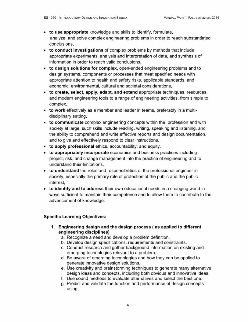
Specific Learning Objectives: 1. Engineering design and the design process ( as applied to different engineering disciplines)
a. Recognize a need and develop a problem definition. b. Develop design specifications, requirements and constraints. c. Conduct research and gather background information on existing and
emerging technologies relevant to a problem. d. Be aware of emerging technologies and how they can be applied to
generate innovative design solutions. e. Use creativity and brainstorming techniques to generate many alternative
design ideas and concepts, including both obvious and innovative ideas. f. Use sound methods to evaluate alternatives and select the best one. g. Predict and validate the function and performance of design concepts
using:
ES 1050 – INTRODUCTORY DESIGN AND INNOVATION STUDIO MANUAL, PART 1, FALL SEMESTER, 2014
5
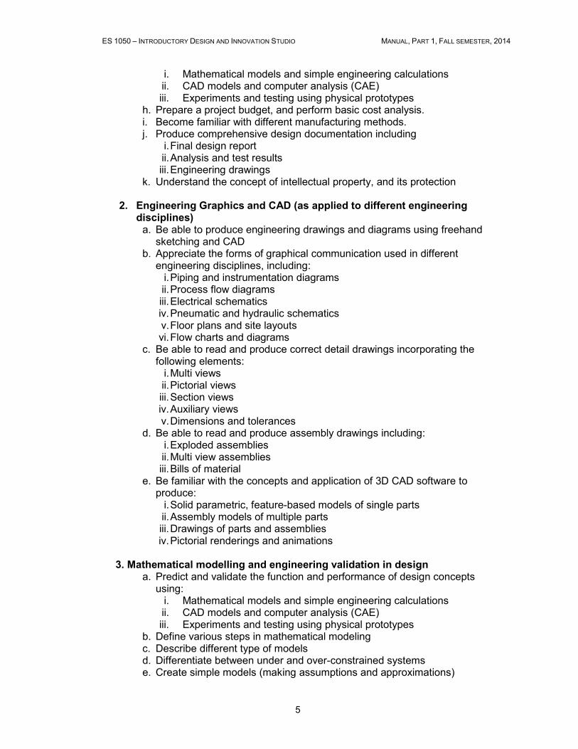
i. Mathematical models and simple engineering calculations ii. CAD models and computer analysis (CAE) iii. Experiments and testing using physical prototypes
h. Prepare a project budget, and perform basic cost analysis. i. Become familiar with different manufacturing methods. j. Produce comprehensive design documentation including
i. Final design report ii. Analysis and test results iii. Engineering drawings
k. Understand the concept of intellectual property, and its protection
2. Engineering Graphics and CAD (as applied to different engineering disciplines)
a. Be able to produce engineering drawings and diagrams using freehand sketching and CAD
b. Appreciate the forms of graphical communication used in different engineering disciplines, including:
i. Piping and instrumentation diagrams ii. Process flow diagrams iii. Electrical schematics iv. Pneumatic and hydraulic schematics v. Floor plans and site layouts vi. Flow charts and diagrams
c. Be able to read and produce correct detail drawings incorporating the following elements:
i. Multi views ii. Pictorial views iii. Section views iv. Auxiliary views v. Dimensions and tolerances
d. Be able to read and produce assembly drawings including: i. Exploded assemblies ii. Multi view assemblies iii. Bills of material
e. Be familiar with the concepts and application of 3D CAD software to produce:
i. Solid parametric, feature-based models of single parts ii. Assembly models of multiple parts iii. Drawings of parts and assemblies iv. Pictorial renderings and animations
3. Mathematical modelling and engineering validation in design
a. Predict and validate the function and performance of design concepts using:
i. Mathematical models and simple engineering calculations ii. CAD models and computer analysis (CAE) iii. Experiments and testing using physical prototypes
b. Define various steps in mathematical modeling c. Describe different type of models d. Differentiate between under and over-constrained systems e. Create simple models (making assumptions and approximations)
ES 1050 – INTRODUCTORY DESIGN AND INNOVATION STUDIO MANUAL, PART 1, FALL SEMESTER, 2014
6
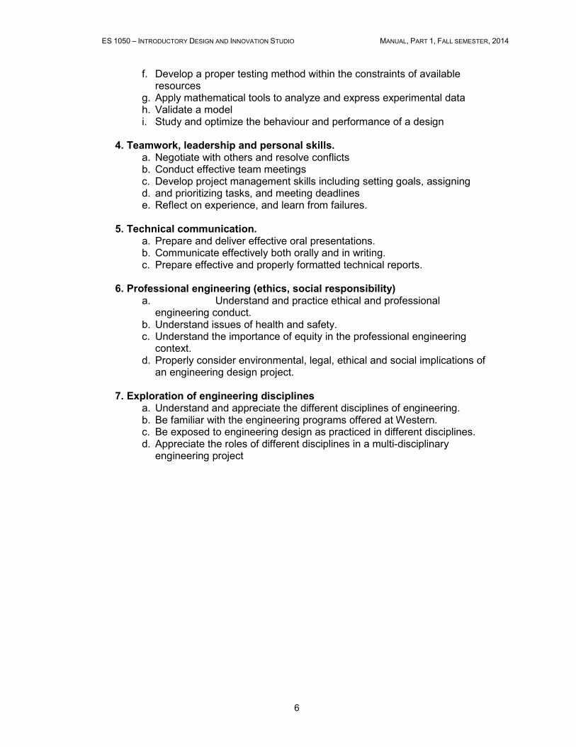
f. Develop a proper testing method within the constraints of available resources
g. Apply mathematical tools to analyze and express experimental data h. Validate a model i. Study and optimize the behaviour and performance of a design
4. Teamwork, leadership and personal skills.
a. Negotiate with others and resolve conflicts b. Conduct effective team meetings c. Develop project management skills including setting goals, assigning d. and prioritizing tasks, and meeting deadlines e. Reflect on experience, and learn from failures.
5. Technical communication. a. Prepare and deliver effective oral presentations. b. Communicate effectively both orally and in writing. c. Prepare effective and properly formatted technical reports.
6. Professional engineering (ethics, social responsibility)
a. Understand and practice ethical and professional engineering conduct.
b. Understand issues of health and safety. c. Understand the importance of equity in the professional engineering
context. d. Properly consider environmental, legal, ethical and social implications of
an engineering design project.
7. Exploration of engineering disciplines a. Understand and appreciate the different disciplines of engineering. b. Be familiar with the engineering programs offered at Western. c. Be exposed to engineering design as practiced in different disciplines. d. Appreciate the roles of different disciplines in a multi-disciplinary
engineering project
ES 1050 – INTRODUCTORY DESIGN AND INNOVATION STUDIO MANUAL, PART 1, FALL SEMESTER, 2014
7
Chapter 2
Course Key Components
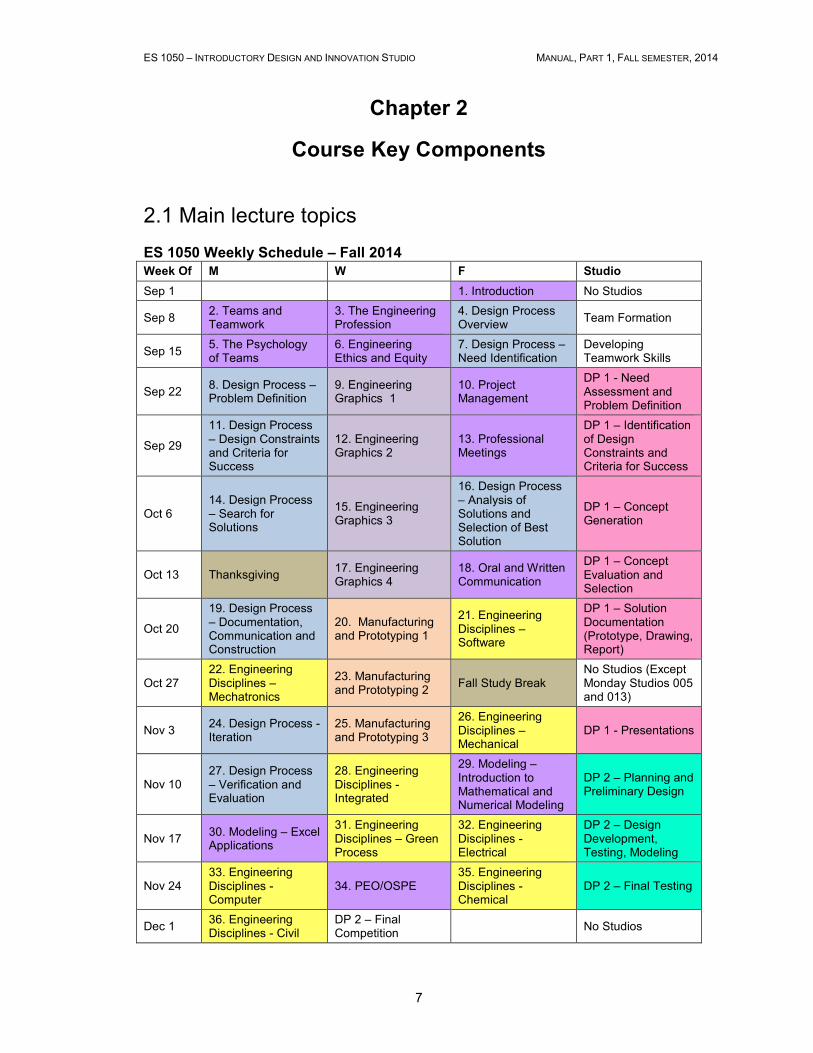
2.1 Main lecture topics ES 1050 Weekly Schedule – Fall 2014
Week Of M W F Studio
Sep 1 1. Introduction No Studios
Sep 8 2. Teams and Teamwork
3. The Engineering Profession
4. Design Process Overview
Team Formation
Sep 15 5. The Psychology of Teams
6. Engineering Ethics and Equity
7. Design Process – Need Identification
Developing Teamwork Skills
Sep 22 8. Design Process – Problem Definition
9. Engineering Graphics 1
10. Project Management
DP 1 - Need Assessment and Problem Definition
Sep 29
11. Design Process – Design Constraints and Criteria for Success
12. Engineering Graphics 2
13. Professional Meetings
DP 1 – Identification of Design Constraints and Criteria for Success
Oct 6 14. Design Process – Search for Solutions
15. Engineering Graphics 3
16. Design Process – Analysis of Solutions and Selection of Best Solution
DP 1 – Concept Generation
Oct 13 Thanksgiving 17. Engineering Graphics 4
18. Oral and Written Communication
DP 1 – Concept Evaluation and Selection
Oct 20
19. Design Process – Documentation, Communication and Construction
20. Manufacturing and Prototyping 1
21. Engineering Disciplines – Software
DP 1 – Solution Documentation (Prototype, Drawing, Report)
Oct 27 22. Engineering Disciplines – Mechatronics
23. Manufacturing and Prototyping 2
Fall Study Break No Studios (Except Monday Studios 005 and 013)
Nov 3 24. Design Process - Iteration
25. Manufacturing and Prototyping 3
26. Engineering Disciplines – Mechanical
DP 1 - Presentations
Nov 10 27. Design Process – Verification and Evaluation
28. Engineering Disciplines - Integrated
29. Modeling – Introduction to Mathematical and Numerical Modeling
DP 2 – Planning and Preliminary Design
Nov 17 30. Modeling – Excel Applications
31. Engineering Disciplines – Green Process
32. Engineering Disciplines - Electrical
DP 2 – Design Development, Testing, Modeling
Nov 24 33. Engineering Disciplines - Computer
34. PEO/OSPE 35. Engineering Disciplines - Chemical
DP 2 – Final Testing
Dec 1 36. Engineering Disciplines - Civil
DP 2 – Final Competition
No Studios
ES 1050 – INTRODUCTORY DESIGN AND INNOVATION STUDIO MANUAL, PART 1, FALL SEMESTER, 2014
8
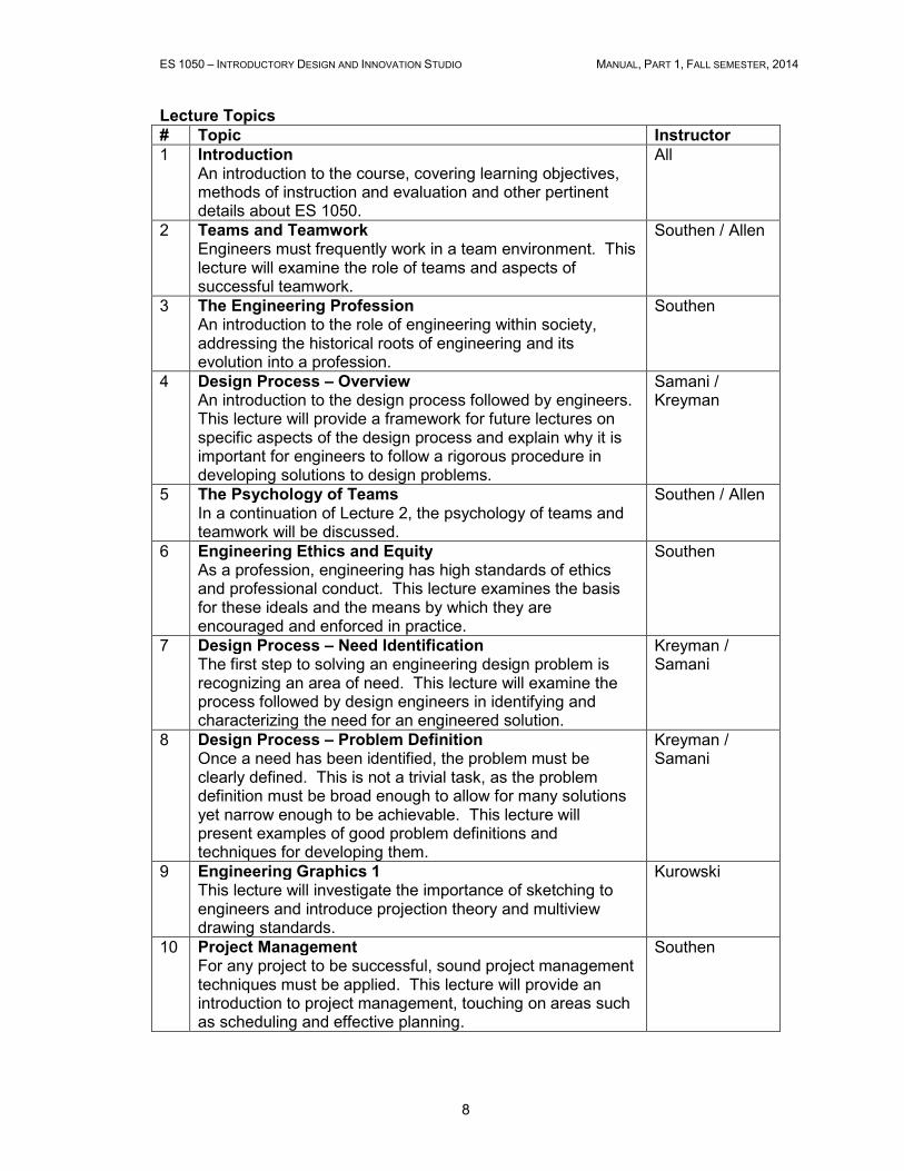
Lecture Topics
# Topic Instructor
1 Introduction An introduction to the course, covering learning objectives, methods of instruction and evaluation and other pertinent details about ES 1050.
All
2 Teams and Teamwork Engineers must frequently work in a team environment. This lecture will examine the role of teams and aspects of successful teamwork.
Southen / Allen
3 The Engineering Profession An introduction to the role of engineering within society, addressing the historical roots of engineering and its evolution into a profession.
Southen
4 Design Process – Overview An introduction to the design process followed by engineers. This lecture will provide a framework for future lectures on specific aspects of the design process and explain why it is important for engineers to follow a rigorous procedure in developing solutions to design problems.
Samani / Kreyman
5 The Psychology of Teams In a continuation of Lecture 2, the psychology of teams and teamwork will be discussed.
Southen / Allen
6 Engineering Ethics and Equity As a profession, engineering has high standards of ethics and professional conduct. This lecture examines the basis for these ideals and the means by which they are encouraged and enforced in practice.
Southen
7 Design Process – Need Identification The first step to solving an engineering design problem is recognizing an area of need. This lecture will examine the process followed by design engineers in identifying and characterizing the need for an engineered solution.
Kreyman / Samani
8 Design Process – Problem Definition Once a need has been identified, the problem must be clearly defined. This is not a trivial task, as the problem definition must be broad enough to allow for many solutions yet narrow enough to be achievable. This lecture will present examples of good problem definitions and techniques for developing them.
Kreyman / Samani
9 Engineering Graphics 1 This lecture will investigate the importance of sketching to engineers and introduce projection theory and multiview drawing standards.
Kurowski
10 Project Management For any project to be successful, sound project management techniques must be applied. This lecture will provide an introduction to project management, touching on areas such as scheduling and effective planning.
Southen
ES 1050 – INTRODUCTORY DESIGN AND INNOVATION STUDIO MANUAL, PART 1, FALL SEMESTER, 2014
9
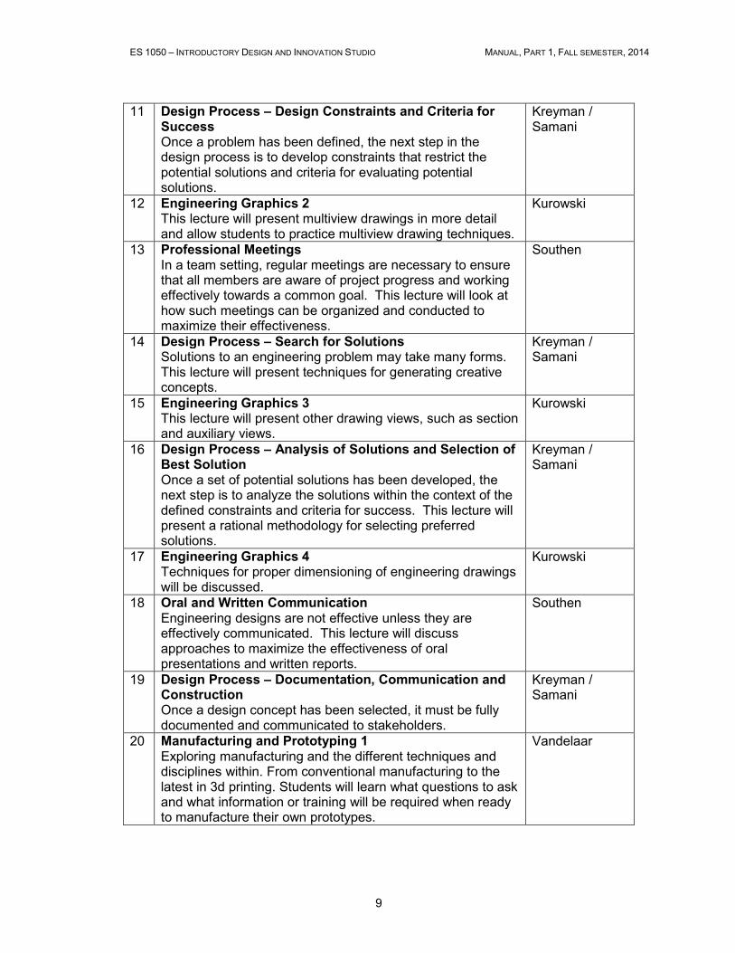
11 Design Process – Design Constraints and Criteria for Success Once a problem has been defined, the next step in the design process is to develop constraints that restrict the potential solutions and criteria for evaluating potential solutions.
Kreyman / Samani
12 Engineering Graphics 2 This lecture will present multiview drawings in more detail and allow students to practice multiview drawing techniques.
Kurowski
13 Professional Meetings In a team setting, regular meetings are necessary to ensure that all members are aware of project progress and working effectively towards a common goal. This lecture will look at how such meetings can be organized and conducted to maximize their effectiveness.
Southen
14 Design Process – Search for Solutions Solutions to an engineering problem may take many forms. This lecture will present techniques for generating creative concepts.
Kreyman / Samani
15 Engineering Graphics 3 This lecture will present other drawing views, such as section and auxiliary views.
Kurowski
16 Design Process – Analysis of Solutions and Selection of Best Solution Once a set of potential solutions has been developed, the next step is to analyze the solutions within the context of the defined constraints and criteria for success. This lecture will present a rational methodology for selecting preferred solutions.
Kreyman / Samani
17 Engineering Graphics 4 Techniques for proper dimensioning of engineering drawings will be discussed.
Kurowski
18 Oral and Written Communication Engineering designs are not effective unless they are effectively communicated. This lecture will discuss approaches to maximize the effectiveness of oral presentations and written reports.
Southen
19 Design Process – Documentation, Communication and Construction Once a design concept has been selected, it must be fully documented and communicated to stakeholders.
Kreyman / Samani
20 Manufacturing and Prototyping 1 Exploring manufacturing and the different techniques and disciplines within. From conventional manufacturing to the latest in 3d printing. Students will learn what questions to ask and what information or training will be required when ready to manufacture their own prototypes.
Vandelaar
ES 1050 – INTRODUCTORY DESIGN AND INNOVATION STUDIO MANUAL, PART 1, FALL SEMESTER, 2014
10
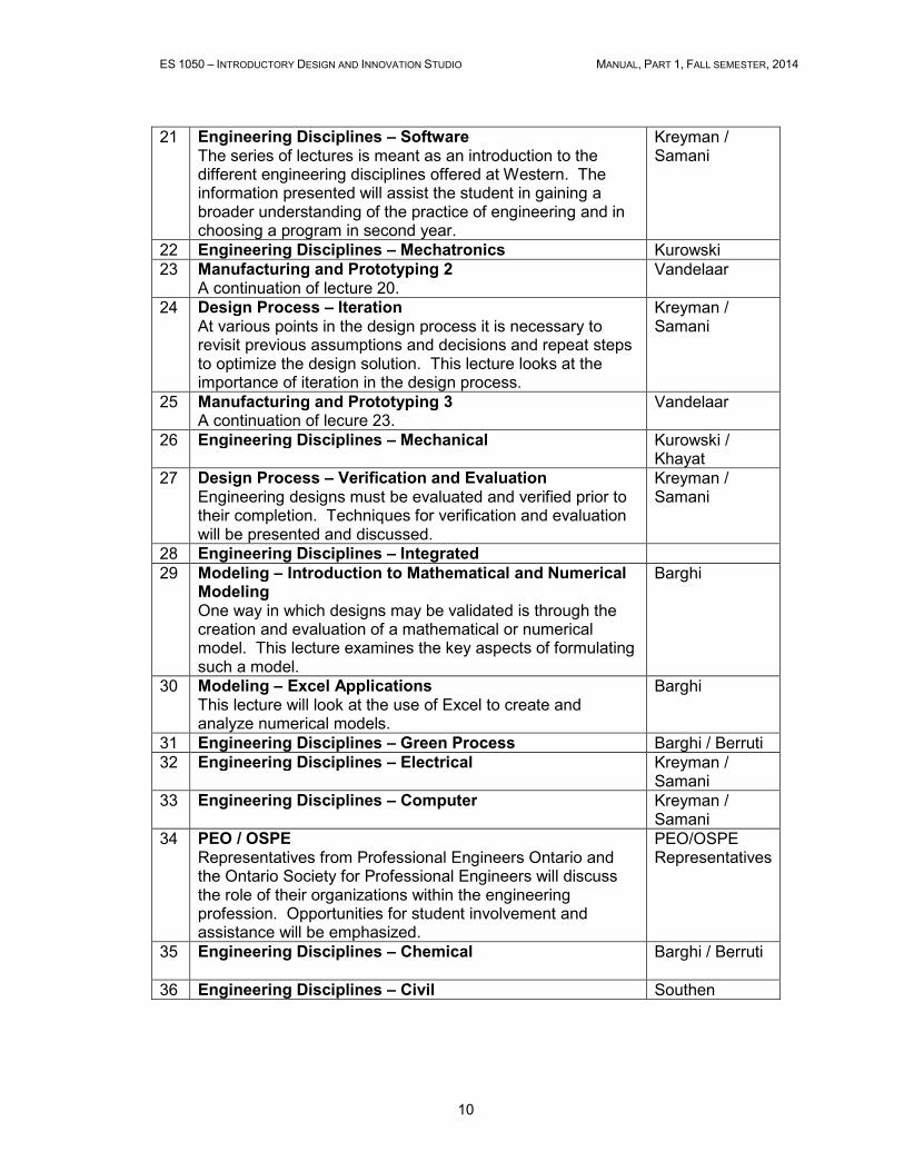
21 Engineering Disciplines – Software The series of lectures is meant as an introduction to the different engineering disciplines offered at Western. The information presented will assist the student in gaining a broader understanding of the practice of engineering and in choosing a program in second year.
Kreyman / Samani
22 Engineering Disciplines – Mechatronics Kurowski 23 Manufacturing and Prototyping 2
A continuation of lecture 20. Vandelaar
24 Design Process – Iteration At various points in the design process it is necessary to revisit previous assumptions and decisions and repeat steps to optimize the design solution. This lecture looks at the importance of iteration in the design process.
Kreyman / Samani
25 Manufacturing and Prototyping 3 A continuation of lecure 23.
Vandelaar
26 Engineering Disciplines – Mechanical Kurowski / Khayat
27 Design Process – Verification and Evaluation Engineering designs must be evaluated and verified prior to their completion. Techniques for verification and evaluation will be presented and discussed.
Kreyman / Samani
28 Engineering Disciplines – Integrated 29 Modeling – Introduction to Mathematical and Numerical
Modeling One way in which designs may be validated is through the creation and evaluation of a mathematical or numerical model. This lecture examines the key aspects of formulating such a model.
Barghi
30 Modeling – Excel Applications This lecture will look at the use of Excel to create and analyze numerical models.
Barghi
31 Engineering Disciplines – Green Process Barghi / Berruti 32 Engineering Disciplines – Electrical Kreyman /
Samani 33 Engineering Disciplines – Computer
Kreyman / Samani
34 PEO / OSPE Representatives from Professional Engineers Ontario and the Ontario Society for Professional Engineers will discuss the role of their organizations within the engineering profession. Opportunities for student involvement and assistance will be emphasized.
PEO/OSPE Representatives
35 Engineering Disciplines – Chemical
Barghi / Berruti
36 Engineering Disciplines – Civil Southen
ES 1050 – INTRODUCTORY DESIGN AND INNOVATION STUDIO MANUAL, PART 1, FALL SEMESTER, 2014
11
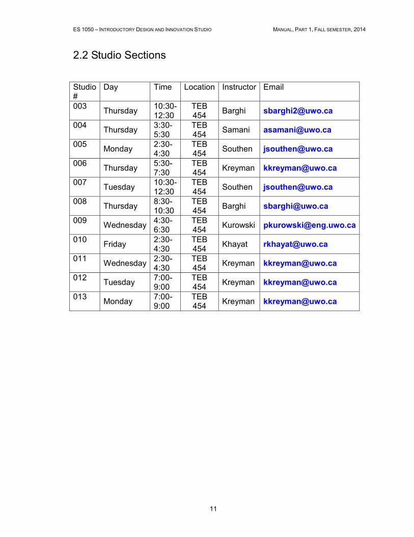
2.2 Studio Sections
Studio #
Day Time Location Instructor Email
003 Thursday
10:30-12:30
TEB 454
Barghi [email protected]
004 Thursday
3:30-5:30
TEB 454
Samani [email protected]
005 Monday
2:30-4:30
TEB 454
Southen [email protected]
006 Thursday
5:30-7:30
TEB 454
Kreyman [email protected]
007 Tuesday
10:30-12:30
TEB 454
Southen [email protected]
008 Thursday
8:30-10:30
TEB 454
Barghi [email protected]
009 Wednesday
4:30-6:30
TEB 454
Kurowski [email protected]
010 Friday
2:30-4:30
TEB 454
Khayat [email protected]
011 Wednesday
2:30-4:30
TEB 454
Kreyman [email protected]
012 Tuesday
7:00-9:00
TEB 454
Kreyman [email protected]
013 Monday
7:00-9:00
TEB 454
Kreyman [email protected]
ES 1050 – INTRODUCTORY DESIGN AND INNOVATION STUDIO MANUAL, PART 1, FALL SEMESTER, 2014
12
2.3 The Design Notebook Each student is to keep a hard-cover design notebook. At the beginning of each
design studio period, the prior week's entries in the design notebook will be
evaluated by the course instructor or teaching assistants.
The design notebook will be collected at the end of the term and assigned a grade
based on both the weekly assessments and the final number of “quality entries”
assessed using the given evaluation criteria. A quality entry is a significant sketch or
drawing of some aspect of the design; a listing of functions, ideas, or other features;
a table such as morphology or decision matrix; or a page of text.
The design notebook is the diary of a design process, from the identification of an
opportunity through to implementation, and so is an important tool in design
development. While portions present the ‘solution’, much of the notebook chronicles
the process and results of discovery including data, insights, goals, decisions,
formulae, experiments, and most importantly, the critical thinking of the designer and
the design team.
The main beneficiary of the design notebook is the designer: it is the
repository of knowledge concerning a problem or opportunity that documents
the designer’s contribution to the solution. Others also benefit: design team
members can review a teammate’s ideas and discoveries; supervisors can
verify an employee’s work to sign off on the validity of results; and legal
disputes over ownership of ideas can be resolved.
Why is a Design Notebook Needed?
A design notebook is the active diary of all design activity, where ideas are formed
and developed. Opening the notebook is one step in the creative process of
engineering design. Documentation occurs in real time rather than as a summary of
what has happened and so provides the skeleton that shapes the body of the design.
The reasons for maintaining the notebook include:
1. Writing things down expresses and records ideas so one can move on. The
designer may efficiently recover these alternatives later, and pursue them as
time permits. Writing or sketching brings closure and prevents forgetting an
idea or design concept while waiting for an opportunity to present it to others.
2. Permitting expression in free form, without devoting time to the structure of
the presentation, due to the informal notebook format. Information and data
can be recorded efficiently.
3. Writing and sketching in the notebook, following the guidelines contained in
this handout, help organize and structure problem solving.
4. Documenting the basis of a design decision allows backtracking to identify
the cause of an “incorrect” decision. This allows one to learn from mistakes,
ES 1050 – INTRODUCTORY DESIGN AND INNOVATION STUDIO MANUAL, PART 1, FALL SEMESTER, 2014
13
and to untangle the effect of the “incorrect” decision from subsequent
decisions.
5. Recording what was done, when it was done, and who did it can be a basis
for resolving “legal” (or grading) disputes.
6. Demonstrating the existence of a design quality control system. To be
certified, a firm must demonstrate its procedures to control the design activity
and must document design output to permit validation.
After-the-fact modifications destroy the credibility of a notebook, and so negatively
impact its usefulness as evidence in any dispute concerning design activities,
perhaps involving a patent (or a grade appeal). For a notebook to be credible when
reviewed by others, the following guidelines are essential:
1. Make all entries in ink to preclude erasure.
2. Leave no large blank spaces on any page. If a blank space is necessary,
draw a large X through the space before writing on the next page.
3. Line out mistakes, noting why the lined-out entry is incorrect.
4. Record information clearly, so that any third party could easily verify one’s
contributions.
5. Date each page and arrange pages in a section in the correct chronological
order.
What is Included in the Notebook?
The notebook should include all documentation written, drawn or copied from
properly cited external sources. It describes individual contributions, calculations,
justifies decisions or conclusions from the information or models applied, and
indicates how such information was used in the design. For example, a decision on
choice of materials for a component would require documented investigations of: the
conditions under which the material would be used; the alternative materials that
could be used; and the requirements and goals that influence choice of material.
Then the alternatives would be ranked in light of the service conditions and
requirements, and a final selection made. Documenting these steps in the notebook
therefore explains the why, what, and how of this design decision.
A simple rule aids deciding what should be included in the design notebook:
“Include everything related to the project, which can be marked on or attached
to a page,unless specifically excluded.”
This definition is all-inclusive, and so avoids endless arguments such as: “I really
would have put it in there, but I thought so-and-so said only such-and-such had to be
included”; or “if only I knew that... Kit would have clearly shown how I did all the
(good) work”. In general, exclusion is the exception rather than the rule. Should an
ES 1050 – INTRODUCTORY DESIGN AND INNOVATION STUDIO MANUAL, PART 1, FALL SEMESTER, 2014
14
idea occur or information be received when the notebook is not available, the idea or
information should be recorded as soon as possible
Is a summary of a conversation with the studio instructor in the hall where he or she
explained the possible implementation of a part of your designed included? Yes it is,
and so is a reference to the source. Is the assignment of tasks agreed upon at a
group meeting included? Yes it is. What about the little piece of scrap iron found
alongside the road that gave you an idea? Well, it can’t be stapled to a page, but a
sketch should be included. In short, if it isn’t documented in the notebook, then it
didn’t happen.
While the objective is to include everything, bulk for the sake of bulk is undesirable.
As a design resource, the notebook is more efficient when unnecessary items are
excluded. For example, instead of inserting the full catalog of a supplier, include only
the specification sheet of an ordered component and contact information for the
supplier (if it isn’t already on the specification sheet).
Required Sections and Format
For this first experience in design and the use of a design notebook, the structure
required for an ES 1050 notebook is defined and should be followed. Later as a
student or Professional Engineer, effective and user-friendly methods are refined for
recording the daily progress of intense design activity. The notebook should be
divided into five sections, each chronologically ordered, in the following sequence:
1. Face Page, Table of Contents (1 page)
2. Time Sheets (8 pages)
3. Schedule/Activities/Progress (8 pages)
4. Personal Notes and Design Development (about 100 pages)
5. Meeting Notes (about 30 pages)
Each page should be uniquely and consecutively numbered. Pages should be
bound and never removed: If someone needs information from a page, photocopy
the page without removing the original.
The date of every entry should be recorded, conventionally in the left margin. There
is no need to have a separate page for each date, and entries may carry from one
page to the next.
1. Face Page, Table of Contents
At the top of the Face (or first) Page, legibly record your name, section number, and
section instructor. To assist the person who might find a lost notebook, provide
contact information including a phone number and email address. In the middle of
the page, record contact information for your course instructors and design team
ES 1050 – INTRODUCTORY DESIGN AND INNOVATION STUDIO MANUAL, PART 1, FALL SEMESTER, 2014
15
members. At the bottom of the page, include a table of contents listing the page
numbers of the six main sections.
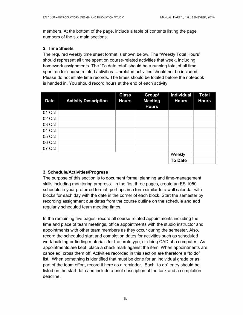
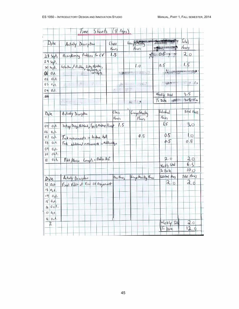
2. Time Sheets
The required weekly time sheet format is shown below. The “Weekly Total Hours”
should represent all time spent on course-related activities that week, including
homework assignments. The “To date total” should be a running total of all time
spent on for course related activities. Unrelated activities should not be included.
Please do not inflate time records. The times should be totaled before the notebook
is handed in. You should record hours at the end of each activity.
Date
Activity Description
Class
Hours
Group/
Meeting
Hours
Individual
Hours
Total
Hours
01 Oct
02 Oct
03 Oct
04 Oct
05 Oct
06 Oct
07 Oct
Weekly
To Date
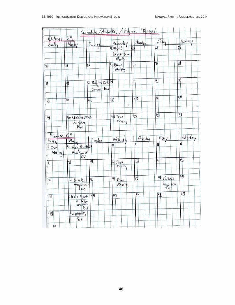
3. Schedule/Activities/Progress
The purpose of this section is to document formal planning and time-management
skills including monitoring progress. In the first three pages, create an ES 1050
schedule in your preferred format, perhaps in a form similar to a wall calendar with
blocks for each day with the date in the corner of each block. Start the semester by
recording assignment due dates from the course outline on the schedule and add
regularly scheduled team meeting times.
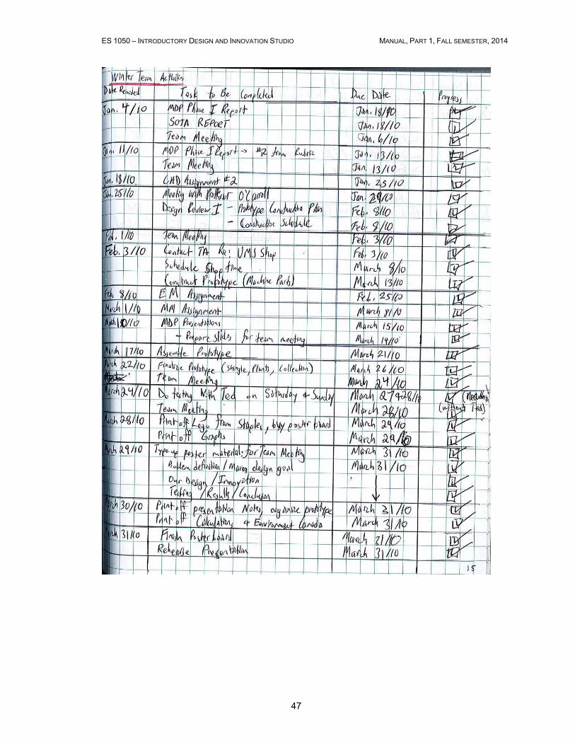
In the remaining five pages, record all course-related appointments including the
time and place of team meetings, office appointments with the studio instructor and
appointments with other team members as they occur during the semester. Also,
record the scheduled start and completion dates for activities such as scheduled
work building or finding materials for the prototype, or doing CAD at a computer. As
appointments are kept, place a check mark against the item. When appointments are
canceled, cross them off. Activities recorded in this section are therefore a “to do”
list. When something is identified that must be done for an individual grade or as
part of the team effort, record it here as a reminder. Each “to do” entry should be
listed on the start date and include a brief description of the task and a completion
deadline.
ES 1050 – INTRODUCTORY DESIGN AND INNOVATION STUDIO MANUAL, PART 1, FALL SEMESTER, 2014
16
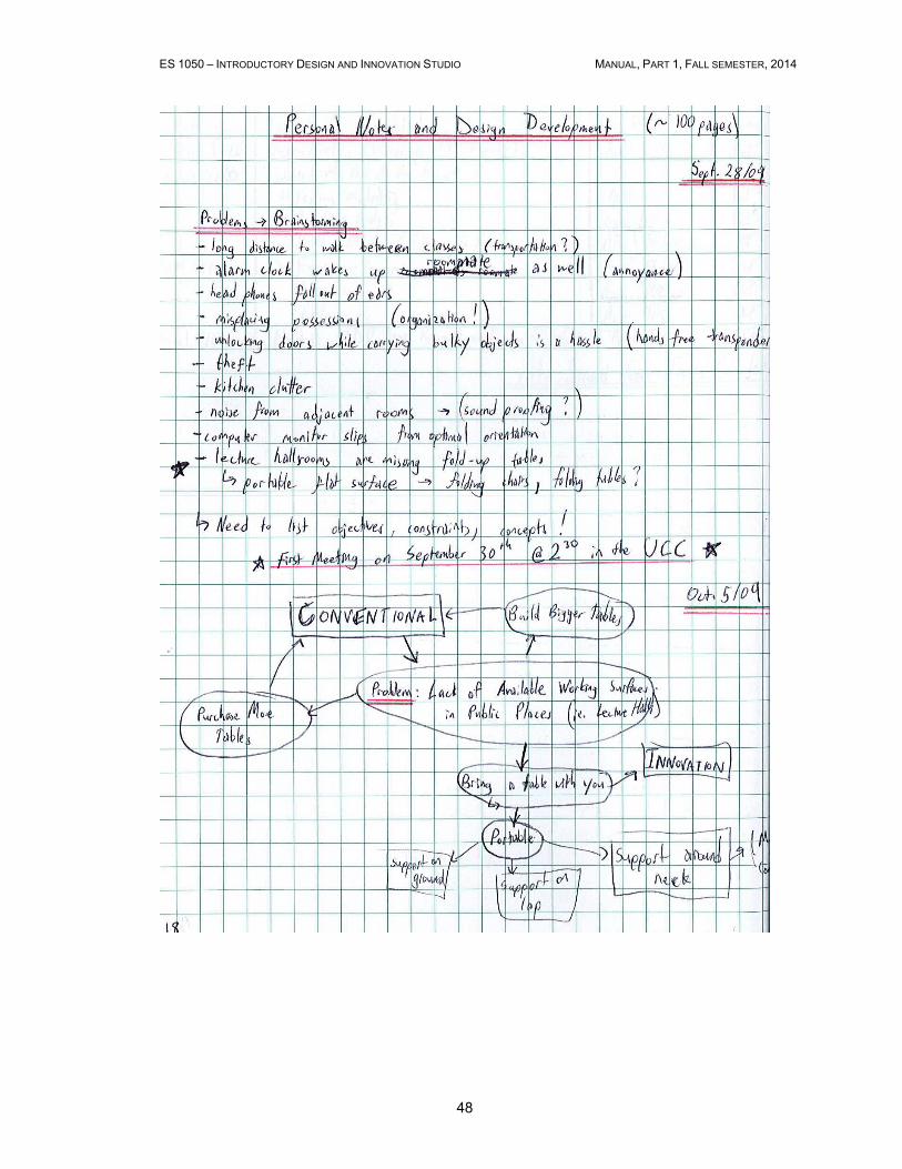
4. Personal Notes and Design Development
This section is where spontaneous thoughts or ideas related to the course and the
design are recorded for later reference. Use written text, a labeled small sketch, or a
combination, and date all entries. Mind maps would be developed in this section.
Also record details of the systematic design development process in this section.
Expand on initial concepts, developing them into workable and credible alternatives.
Record formulae, calculations, expanded sketches, and experimental data. Use a
two-page format throughout: begin at the top of the left page, work down the page
and when you reach the bottom carry the work over to the right page.
Three main design activities dominate this section of the notebook: idea
development, calculation, and experimental analysis. Guidance for documenting
these activities is provided below.
4.1 Idea Development
This activity gives substance and provides detail for ideas and thoughts. The
following four sections must be named and completed to fully record and develop an
idea:
1. Problem Definition (or Opportunity). Define the problem or opportunity that
the idea is supposed to solve: what is the objective?
2. Attributes and constraints. List the attributes that can be used to assess
the merit of an idea and any constraints of the problem that limit the solution.
3. Basic science. Describe the basic scientific principle(s) that are the
foundation of the idea or further define the problem and its solution.
4. Description. Describe the idea using a juxtaposition of words, sketches or
questions. Present and expand the idea methodically, starting with a general
description and adding detail in a step-by-step fashion in response to your
questions about the design. A reader should be able to interpret your idea
and to understand the reasoning behind the details.
While this serial ordering imposes a structure for recording your work, do not feel that
one section must be completed before starting the next or that you cannot backtrack.
Use the structure as a tool to assure completeness and to direct your thinking: it is
more than a simple list of steps that must be followed. This same structure can be
used to summarize a literature search.
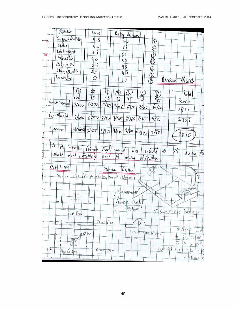
4.2 Calculation
In design, calculations are more than arithmetic operations between numbers – they
represent the application of a mathematical model to resolve all or part of a problem.
The following sections are necessary to document a design calculation:
1. Problem Definition. Define the problem in terms that suggest the use of a
mathematical model.
ES 1050 – INTRODUCTORY DESIGN AND INNOVATION STUDIO MANUAL, PART 1, FALL SEMESTER, 2014
17
2. Attributes and constraints. List the attributes and constraints of the problem
and solution.
3. Basic science/formulation/data. Present the mathematical model(s) and
data that will be used in the calculations. Explain notation and units.
4. References. List references for each mathematical models and data set
used, so others can independently verify the work.
5. Calculation. Show the calculation(s) or the results of calculation if a
computer is used. Often results are presented in tables or figures, using
sensitivity analyses involving multiple calculations to assess the impact of
varying specified parameters on the result.
6. Is it reasonable? The ability to answer this question explicitly yes or no is
arguably the most essential skill of an engineer. Does the order of magnitude
look correct? Check and confirm units and unit conversion factors in all
calculations. Does a simplified calculation give a similar answer?
7. Conclusions/Recommendations/Action. Based on the results and
considering the goals, present the result in terms of application to the design
problem under study.
Any calculation is done in the context of a particular design solution. Because
parameters of a design usually change as the design evolves, documentation must
allow any calculation to be easily revisited to rapidly obtain different numerical results
using new parameter values.
4.3 Experimental Analysis
Design often involves collection and analysis of experimental data. The guidelines for
presenting experiments are presented in the laboratory manual.
During the time of the prototype construction, the problems solved by the designer
may not fit cleanly into these templates. For example, if a bracket is needed, the
focus is on the shape and dimensions of the bracket rather than formulae and
calculation. Nevertheless, such design work should follow a methodological process
in the spirit of the guidelines. To document problems of dimensions and shape during
prototype construction, date the entries, describe the need as a Problem Definition,
and label sketches to explain the design. Good documentation of prototype
debugging activities provides insight into problem identification and can serve as a
starting point for system redesign. Document debugging activities by listing the
suspected causes, listing the debug test performed and recording the result of the
test.
4.4 Attachments and External References
Attachments, such as single pages of a research article referenced in other work,
should be cut to the page size or less and should be permanently attached, e.g. with
staples, glue or tape. Any such attachments that are not your own effort should be
completely referenced with all information needed to relocate the material if lost.
ES 1050 – INTRODUCTORY DESIGN AND INNOVATION STUDIO MANUAL, PART 1, FALL SEMESTER, 2014
18
5. Meeting Notes (or Minutes)
The following information should be included in your notes on any meeting:
1. The date, time, and location
2. Who attended and who advised beforehand that they would be unable to
attend.
3. Information that was exchanged – some document this in considerable detail,
others try to succinctly capture the highlights.
4. Action items: an unambiguous description of tasks to be performed, who will
carry them out, and when they will be completed.
5. Date, time, location, and possibly the main agenda items of the next meeting.
Summary
The design notebook is an essential communication tool in the design process. It
records research, thought process, and the development of a design. In short, it
justifies one’s design work to others on the team, including the supervisor. Poor
notebooks are highly correlated with poor designers.
ES 1050 – INTRODUCTORY DESIGN AND INNOVATION STUDIO MANUAL, PART 1, FALL SEMESTER, 2014
19
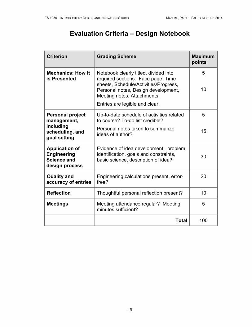
Evaluation Criteria – Design Notebook
Criterion Grading Scheme Maximum points
Mechanics: How it is Presented
Notebook clearly titled, divided into required sections: Face page, Time sheets, Schedule/Activities/Progress, Personal notes, Design development, Meeting notes, Attachments.
Entries are legible and clear.
5
10
Personal project management, including scheduling, and goal setting
Up-to-date schedule of activities related to course? To-do list credible?
Personal notes taken to summarize ideas of author?
5
15
Application of Engineering Science and design process
Evidence of idea development: problem identification, goals and constraints, basic science, description of idea?
30
Quality and accuracy of entries
Engineering calculations present, error-free?
20
Reflection Thoughtful personal reflection present? 10
Meetings Meeting attendance regular? Meeting minutes sufficient?
5
Total 100
ES 1050 – INTRODUCTORY DESIGN AND INNOVATION STUDIO MANUAL, PART 1, FALL SEMESTER, 2014
20
2.4 Design Project I – Creativity
2.4.1 Goal of the Creativity Project, Deliverables and Evaluation
This project is meant to be a “snapshot” of the Engineering Design Process. The
objectives of Design Project I are to practice and obtain feedback on the various
steps that make up the engineering design process, and to learn to utilize creativity
and innovation in engineering design. While the main focus in this project is creativity
and innovation, design validation using experimentation or mathematical modeling is
encouraged. This experience will provide you with practice and insights that will be
useful in subsequent course projects and throughout your engineering career.
Goal of the Creativity Project:
Your ES 1050 Design Team is hereby contracted to:
Design or modify the existing design of an everyday object to maximize the
safety of the object.
Your final design should use materials and parts that have a combined commercial
value less than $15 CDN excluding taxes and shipping.
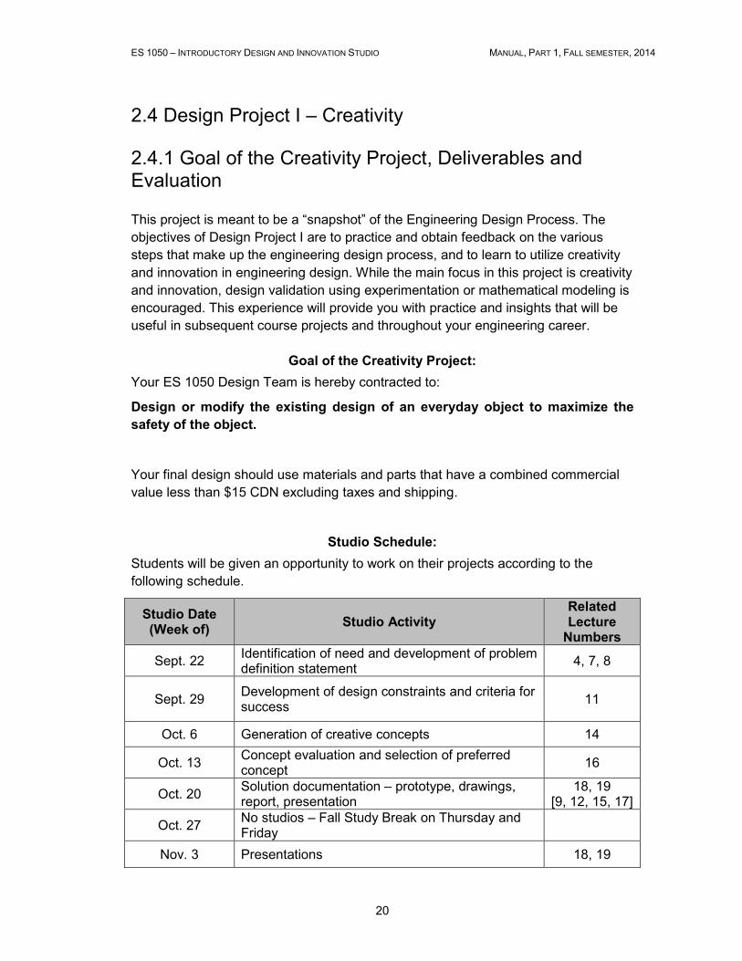
Studio Schedule:
Students will be given an opportunity to work on their projects according to the
following schedule.
Studio Date (Week of)
Studio Activity Related Lecture Numbers
Sept. 22 Identification of need and development of problem definition statement
4, 7, 8
Sept. 29 Development of design constraints and criteria for success
11
Oct. 6 Generation of creative concepts 14
Oct. 13 Concept evaluation and selection of preferred concept
16
Oct. 20 Solution documentation – prototype, drawings, report, presentation
18, 19 [9, 12, 15, 17]
Oct. 27 No studios – Fall Study Break on Thursday and Friday
Nov. 3 Presentations 18, 19
ES 1050 – INTRODUCTORY DESIGN AND INNOVATION STUDIO MANUAL, PART 1, FALL SEMESTER, 2014
21
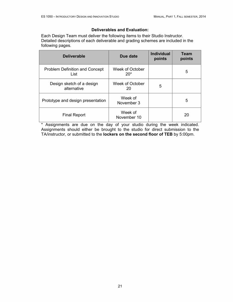
Deliverables and Evaluation:
Each Design Team must deliver the following items to their Studio Instructor. Detailed descriptions of each deliverable and grading schemes are included in the following pages.
Deliverable Due date Individual points
Team points
Problem Definition and Concept List
Week of October 20*
5
Design sketch of a design alternative
Week of October 20
5
Prototype and design presentation Week of
November 3 5
Final Report Week of
November 10 20
* Assignments are due on the day of your studio during the week indicated. Assignments should either be brought to the studio for direct submission to the TA/instructor, or submitted to the lockers on the second floor of TEB by 5:00pm.
ES 1050 – INTRODUCTORY DESIGN AND INNOVATION STUDIO MANUAL, PART 1, FALL SEMESTER, 2014
22
2.4.2 Problem Definition and Concept List
Requirements:
Your design team shall submit a brief report outlining the detailed problem definition that you have chosen, a set of objectives and constraints applicable to the solution of this problem, a list of concepts which represent potential solutions to this problem and a description of the innovations and creativity techniques embodied in your design. You should define the problem very specifically. For example, your team might define the problem as “design a better can opener”. However, this is a goal and not a problem definition. Before defining the problem, you must first establish whether there is a need for a better can opener. If there is a need, consider what is wrong with existing can openers. Are they too heavy? Do they not work properly (e.g. they bind, unsafe, or slip off the lid)? Are they too difficult to operate? Do you know what improvements have been made to can openers over the past years? Your team must thoroughly explore and continue to redefine the problem in order to develop a direction and purpose for your design. Once the problem is defined, you should try to identify design objectives and constraints. Objectives describe how your design will meet the overall goal in qualitative terms. Constraints describe quantitative limits that restrict your design. Sometimes the constraint is a quantitative description of an objective. For example, an objective might be to make the device as lightweight as possible (Note: that objective combined with other objectives could meet your overall goal: “a better can opener”). A constraint would be that the device must weigh less than 50 g. After defining the problem and identifying objectives and constraints, you should generate as many concepts or ideas as possible for how to achieve the design objectives. For example, to open cans, you might think of alternatives such as: electric can openers or laser cutters, or alternatively use thinking out-of- the-box approach to solve the problem of opening cans by designing containers that are easier to open. With the latter approach you might think of pop-top cans, alternative containers etc. The objective is to be creative at this stage: the alternatives can be compared and evaluated later. The emphasis will be on creative or innovative solutions and not a re-definition of an existing solution or approach. In terms of target customers, be careful to define the problem as broadly as possible. For example, if you define the problem above as “design a can opener for people with arthritis”, you eliminate a lot of possible solutions like redesigning the containers themselves so that they are easier to open. The latter solution represents a more creative approach that can lead to innovation.
ES 1050 – INTRODUCTORY DESIGN AND INNOVATION STUDIO MANUAL, PART 1, FALL SEMESTER, 2014
23
Evaluation Criteria:
Your submission is not to exceed 1500 words or 4 pages (not including appendices)
and should include the following sections:
1. Need Identification and Problem Definition: Provide a brief discussion of
the area of need identified by your team and a succinct summary of the
problem that you are trying to solve.
2. Design Constraints and Criteria for Success: List the detailed design
objectives and constraints that were developed to achieve the design goal.
3. Concept Generation: Describe at least three concepts you have generated
using creativity techniques. Small sketches may be helpful in communicating
these concepts.
4. Innovations and Creativity: Describe the innovations developed and
considered during the design process. Identify the creativity stimulation
techniques that your team used to develop the innovative and creative
alternatives. Include a one page appendix where you demonstrate your
effective use of creative thinking techniques (e.g. mind map).
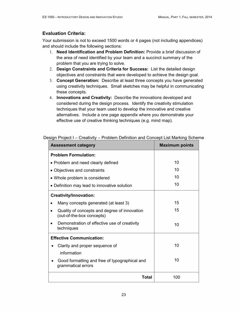
Design Project I – Creativity – Problem Definition and Concept List Marking Scheme
Assessment category Maximum points
Problem Formulation:
• Problem and need clearly defined
• Objectives and constraints
• Whole problem is considered
• Definition may lead to innovative solution
10
10
10
10
Creativity/Innovation:
• Many concepts generated (at least 3)
• Quality of concepts and degree of innovation (out-of-the-box concepts)
• Demonstration of effective use of creativity techniques
15
15
10
Effective Communication:
• Clarity and proper sequence of
information
• Good formatting and free of typographical and grammatical errors
10
10
Total 100
ES 1050 – INTRODUCTORY DESIGN AND INNOVATION STUDIO MANUAL, PART 1, FALL SEMESTER, 2014
24
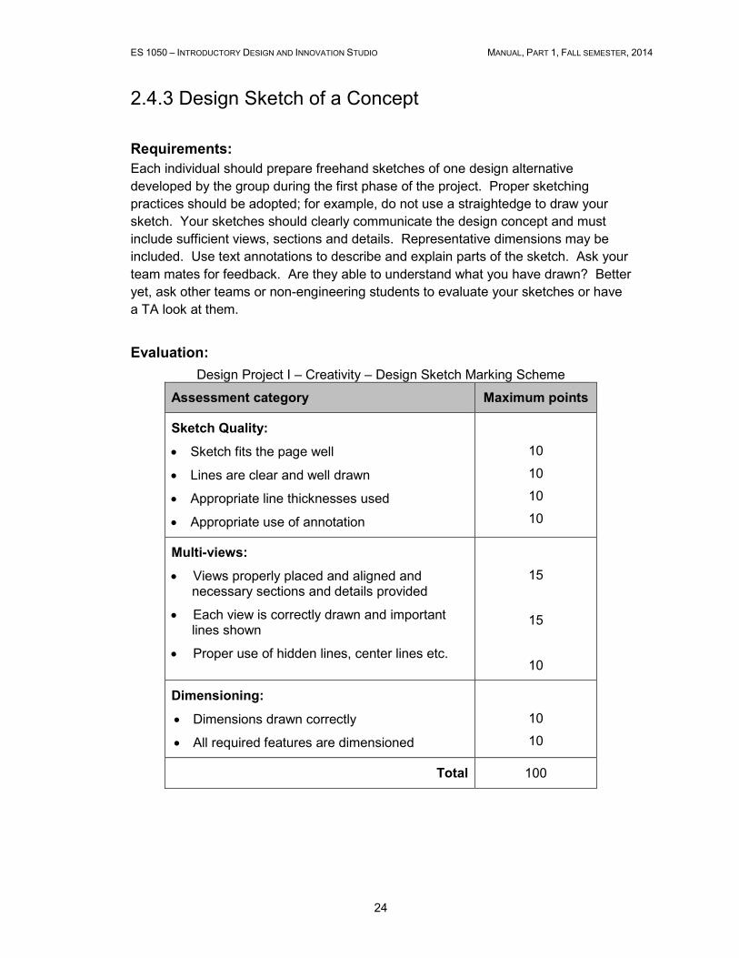
2.4.3 Design Sketch of a Concept
Requirements:
Each individual should prepare freehand sketches of one design alternative
developed by the group during the first phase of the project. Proper sketching
practices should be adopted; for example, do not use a straightedge to draw your
sketch. Your sketches should clearly communicate the design concept and must
include sufficient views, sections and details. Representative dimensions may be
included. Use text annotations to describe and explain parts of the sketch. Ask your
team mates for feedback. Are they able to understand what you have drawn? Better
yet, ask other teams or non-engineering students to evaluate your sketches or have
a TA look at them.
Evaluation:
Design Project I – Creativity – Design Sketch Marking Scheme
Assessment category Maximum points
Sketch Quality:
• Sketch fits the page well
• Lines are clear and well drawn
• Appropriate line thicknesses used
• Appropriate use of annotation
10
10
10
10
Multi-views:
• Views properly placed and aligned and necessary sections and details provided
• Each view is correctly drawn and important lines shown
• Proper use of hidden lines, center lines etc.
15
15
10
Dimensioning:
• Dimensions drawn correctly
• All required features are dimensioned
10
10
Total 100
ES 1050 – INTRODUCTORY DESIGN AND INNOVATION STUDIO MANUAL, PART 1, FALL SEMESTER, 2014
25
2.4.4 Prototype and Design Presentation
Requirements:
Each team will give a brief (7 minute) presentation of their design followed by 2
minutes for questions and answers. The presentation should provide at a minimum
the important information listed below:
• The need for the solutions and innovations communicated in your design.
• Justifications of innovations and novel aspects of your design.
• A graphical depiction of your design (layout or labeled figure with
dimensions)
• A prototype of your design (the prototype does not need to be fully
functional)
• A product specification handout (1 page) which “sells” your design
The goal of the Design Presentation is to both demonstrate and "sell" your design
ideas.
All team members must participate in all presentations.
PowerPoint, Prezi, and/or video presentations may be used. The presentation should
be well prepared and practiced. Avoid needless details since your team has only 7
minutes.
ES 1050 – INTRODUCTORY DESIGN AND INNOVATION STUDIO MANUAL, PART 1, FALL SEMESTER, 2014
26
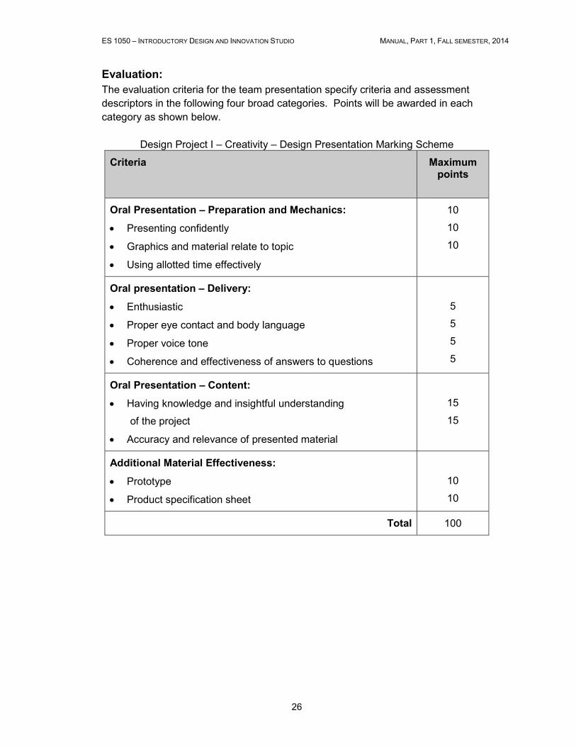
Evaluation:
The evaluation criteria for the team presentation specify criteria and assessment
descriptors in the following four broad categories. Points will be awarded in each
category as shown below.
Design Project I – Creativity – Design Presentation Marking Scheme
Criteria
Maximum points
Oral Presentation – Preparation and Mechanics:
• Presenting confidently
• Graphics and material relate to topic
• Using allotted time effectively
10
10
10
Oral presentation – Delivery:
• Enthusiastic
• Proper eye contact and body language
• Proper voice tone
• Coherence and effectiveness of answers to questions
5
5
5
5
Oral Presentation – Content:
• Having knowledge and insightful understanding
of the project
• Accuracy and relevance of presented material
15
15
Additional Material Effectiveness:
• Prototype
• Product specification sheet
10
10
Total 100
ES 1050 – INTRODUCTORY DESIGN AND INNOVATION STUDIO MANUAL, PART 1, FALL SEMESTER, 2014
27
2.4.5 Final Design Report
Your team must prepare a final report summarizing the process and outcome of
Design Project I. The report should follow conventions for proper technical writing as
discussed in the lectures. Your report will be evaluated by course instructors and/or
teaching assistants, so you may consider your audience to have a relatively high
degree of technical knowledge.
Requirements:
The design report submitted as part of the Project I shall be written using font size 11
points and 1.5 line spacing and shall include, at least, the following items (page
length is suggestive and not restrictive):
1. Title Page: containing project title, course name and number, studio section,
team number, names and student numbers of team members and date of
submission.
2. Executive Summary: A one-paragraph summary of the report, intended for
an executive audience. Should contain only the most important aspects of
the report, primarily focused on the final conclusions.
3. Table of Contents: Shows the contents and arrangement of the report.
Major headings of the report should be included. Include a list of figures, list
of tables and list of appendices if necessary.
4. Introduction: Identify the need and overall goals of the design, state why
your design is important and provide a brief description of the design and the
general content of the report. What will the reader find in the following
sections? Is there an interesting outcome of the design work? Convince the
reader to read on. (1 page).
5. Design Constraints and Criteria for Success: List the detailed design
objectives that were developed to achieve the design goal. Define all
constraints identified and applied during the design process. (1 page).
6. Innovations and Creativity: Describe the innovations developed and
considered during the design process. Identify the creativity techniques that
you used to develop the innovative and creative alternatives. (1 page)
7. Evaluation: Identify the criteria developed and used to select your final
design. Make the criteria as meaningful as possible by having preliminary
designs (sketches and details) for at least 3 concepts. Show the method
used to select the preferred alternative for detailed design and prototyping.
(1-2 pages).
8. Detailed Drawing: A graphical depiction of your design must be included.
This should comprise a detailed drawing or set of drawings which fully
describes your design. Label the drawing and include dimensions. Note that
ES 1050 – INTRODUCTORY DESIGN AND INNOVATION STUDIO MANUAL, PART 1, FALL SEMESTER, 2014
28
free-hand sketching is not intended in this part, and you may use a straight
edge for any hand drawings. CAD (SolidWorks, AutoCAD) drawings are also
acceptable, although not required. (1-2 pages).
9. Description of Prototype: Provide a meaningful and concise description of
your design prototype. Discuss how its development furthered the design
process and how it might be used should the design process continue. (1
page).
10. Conclusion: Describe the outcome of your design and the design process
your team went through including the iterations that were made during the
design process. Discuss the lessons learned during the prototyping activities
and during attempts to incorporate engineering science in the design process
and provide recommendations for future design improvement. (1-2 pages).
11. Appendices: Include in an appendix any supporting information which may
rightly belong in the report’s body but, if included, would disrupt and clutter
the major narrative. Examples of material that may be best included in an
appendix: product-specification handout, detailed drawings, installation and
operation instructions, testing data, etc. Include your team’s final Grade
Distribution Form (see below). This form shall be supported by description of
each team member contribution to justify each team member’s assigned
percentage of grade.
ES 1050 – INTRODUCTORY DESIGN AND INNOVATION STUDIO MANUAL, PART 1, FALL SEMESTER, 2014
29
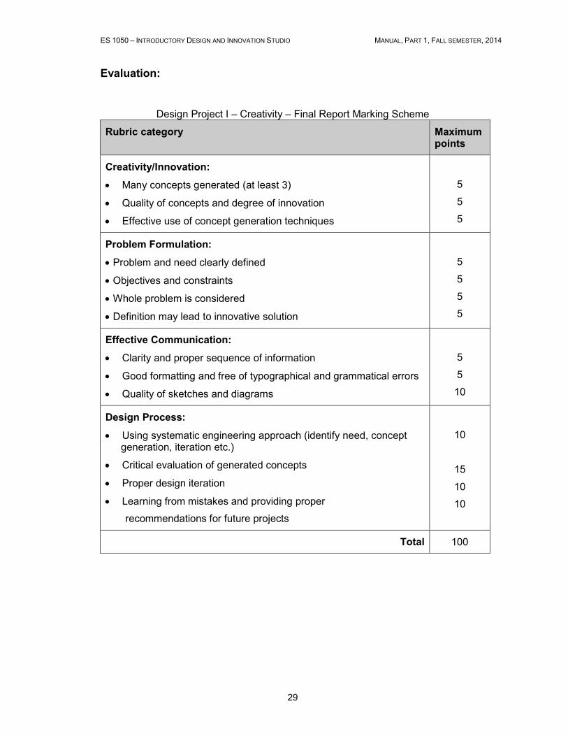
Evaluation:
Design Project I – Creativity – Final Report Marking Scheme
Rubric category Maximum points
Creativity/Innovation:
• Many concepts generated (at least 3)
• Quality of concepts and degree of innovation
• Effective use of concept generation techniques
5
5
5
Problem Formulation:
• Problem and need clearly defined
• Objectives and constraints
• Whole problem is considered
• Definition may lead to innovative solution
5
5
5
5
Effective Communication:
• Clarity and proper sequence of information
• Good formatting and free of typographical and grammatical errors
• Quality of sketches and diagrams
5
5
10
Design Process:
• Using systematic engineering approach (identify need, concept generation, iteration etc.)
• Critical evaluation of generated concepts
• Proper design iteration
• Learning from mistakes and providing proper
recommendations for future projects
10
15
10
10
Total 100
ES 1050 – INTRODUCTORY DESIGN AND INNOVATION STUDIO MANUAL, PART 1, FALL SEMESTER, 2014
30
2.4.6 Design Team Grade Distribution Criteria
The form on the following page shall be used to allocate grades to individuals for all
group submissions comprising Design Project 1. Submission of the form requires the
team to reflect on the contributions of individual team members, and provides the
Studio Instructor with an indication of the team’s progress. Team grades for these
deliverables will not be released by the Studio Instructor until this form has
been completed and signed by all team members.
Ideally, each team member will contribute equally to the overall work of the team. A
Team is most successful when individual members are responsible for aspects of the
work that they find particularly interesting or enjoyable. The team’s efforts should be
organized in a way that keeps all group members involved and on track, each
contributing roughly equal effort that results in roughly equal productivity.
Criteria often used to evaluate team performance include:
1. Decision-making: do all team members contribute to the decision-making process?
2. Social interaction: do team members respect and encourage the views of other team members?
3. Participation: do all members participate equally in a positive way? 4. On task: are team members consistently on task, or do they waste time on
irrelevant activities? 5. Group structure and function: are team members, under the guidance of
the lead engineer, able to break the project down into a series of tasks which are then distributed equally, and completed on time?
If team members cannot agree on the team grade distribution, they will arrange to
meet with their Studio Instructor who will mediate the dispute. If no consensus is
reached, the studio instructor shall review the supporting document (referred to in the
“Appendices” item of the “Design Report Requirements”) that describes individual
team member contribution, and shall assign a team grade distribution accordingly.
If any team member of a team of four is assigned a team grade percentage
greater than 35% or less than 15%, (s)he may be asked to meet with the Studio
Instructor to review the allocation.
Each student grade will be calculated according to the total mark of the report
and the assigned member grade percentage. For example a team of four who
receive a total mark of 80 out of 10 for their report agree on a grade
distribution of 25%, 25%, 30% and 20%. Member grades will be as follows:
4 ××××80××××0.25 = 80
4 ××××80××××0.25 = 80
4 ××××80××××0.30 = 96
4 ××××80××××0.20 = 64
ES 1050 – INTRODUCTORY DESIGN AND INNOVATION STUDIO MANUAL, PART 1, FALL SEMESTER, 2014
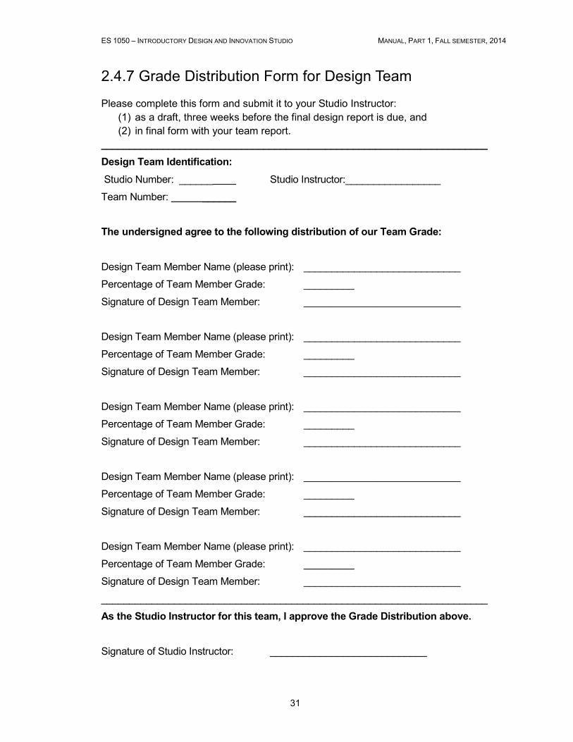
31
2.4.7 Grade Distribution Form for Design Team
Please complete this form and submit it to your Studio Instructor:
(1) as a draft, three weeks before the final design report is due, and
(2) in final form with your team report.
_____________________________________________________________________
Design Team Identification:
Studio Number: ______ Studio Instructor:_________________
Team Number: ______
The undersigned agree to the following distribution of our Team Grade:
Design Team Member Name (please print): ____________________________
Percentage of Team Member Grade: _________
Signature of Design Team Member: ____________________________
Design Team Member Name (please print): ____________________________
Percentage of Team Member Grade: _________
Signature of Design Team Member: ____________________________
Design Team Member Name (please print): ____________________________
Percentage of Team Member Grade: _________
Signature of Design Team Member: ____________________________
Design Team Member Name (please print): ____________________________
Percentage of Team Member Grade: _________
Signature of Design Team Member: ____________________________
Design Team Member Name (please print): ____________________________
Percentage of Team Member Grade: _________
Signature of Design Team Member: ____________________________
_____________________________________________________________________
As the Studio Instructor for this team, I approve the Grade Distribution above.
Signature of Studio Instructor: ____________________________
ES 1050 – INTRODUCTORY DESIGN AND INNOVATION STUDIO MANUAL, PART 1, FALL SEMESTER, 2014
32
2.5 Design Project II - Iteration
2.5.1 Goal of the project and constrains
Engineering designs are rarely optimized with one pass through the design process. In the first project, your team likely identified numerous areas in which your design could be improved with further testing, assessment and refinement, if you had the time. This second project will focus on this iterative nature of design. Your team will be given a power source, consisting of a standard mouse trap. It is your task to design an apparatus that will use this power source to launch a projectile with the objective of hitting a target located at an unknown distance 2-10 m away from the apparatus. Your design should thus be capable of achieving a range of different distances. You will have five studio sessions to design, construct, test analyze and redesign your apparatus. Additional details are indicated below.
Constraints:
• One mouse trap shall be the sole source of power for your apparatus. • Your team will be provided with two mouse traps (one primary and one spare)
at the start of the project. Only one approved mouse trap will be permitted for use in your apparatus. Should all of your mouse traps fail (break) during testing, you may obtain additional mouse traps from your studio instructor, although a penalty in the performance evaluation of your team will result.
• The apparatus may only be constructed of recycled and used materials which are approved by the studio instructor. No preassembled components may be included.
• The point of impact of your projectile will determine its accuracy, regardless of any subsequent movement.
• No hazardous materials are permitted.
ES 1050 – INTRODUCTORY DESIGN AND INNOVATION STUDIO MANUAL, PART 1, FALL SEMESTER, 2014
33
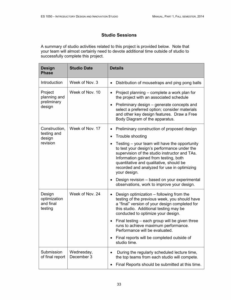
Studio Sessions
A summary of studio activities related to this project is provided below. Note that your team will almost certainly need to devote additional time outside of studio to successfully complete this project.
Design Phase
Studio Date Details
Introduction Week of Nov. 3 • Distribution of mousetraps and ping pong balls
Project planning and preliminary design
Week of Nov. 10 • Project planning – complete a work plan for the project with an associated schedule
• Preliminary design – generate concepts and select a preferred option; consider materials and other key design features. Draw a Free Body Diagram of the apparatus.
Construction, testing and design revision
Week of Nov. 17 • Preliminary construction of proposed design
• Trouble shooting
• Testing – your team will have the opportunity to test your design’s performance under the supervision of the studio instructor and TAs. Information gained from testing, both quantitative and qualitative, should be recorded and analyzed for use in optimizing your design.
• Design revision – based on your experimental observations, work to improve your design.
Design optimization and final testing
Week of Nov. 24 • Design optimization – following from the testing of the previous week, you should have a “final” version of your design completed for this studio. Additional testing may be conducted to optimize your design.
• Final testing – each group will be given three runs to achieve maximum performance. Performance will be evaluated.
• Final reports will be completed outside of studio time.
Submission of final report
Wednesday, December 3
• During the regularly scheduled lecture time, the top teams from each studio will compete.
• Final Reports should be submitted at this time.
ES 1050 – INTRODUCTORY DESIGN AND INNOVATION STUDIO MANUAL, PART 1, FALL SEMESTER, 2014
34
2.5.2 Deliverables and Evaluation
Your final grade for this project (out of 30) will be based on your teams’ performance in the following:
Performance (12)
Your team will receive a grade from the studio instructor and TAs based on the performance of your design during the final testing phase of the project. The mark will be based on performance (6), originality (2), compliance (2) and aesthetics (2).
Critique (3)
Your team will assess the performance of two other groups. A portion of your final mark will be based on these design critiques. A detailed description of the critique is included below.
Final Report (15)
Your team will prepare and submit a final report following the outline indicated below.

ES 1050 – INTRODUCTORY DESIGN AND INNOVATION STUDIO MANUAL, PART 1, FALL SEMESTER, 2014
35
2.5.3 Critique Form
Part of being a successful engineering designer is being able to recognize the strengths and weaknesses of others’ work, and providing constructive criticism. It is equally important to be able to reflect upon criticism and suggestions offered by others. The following form will be made available during the final testing phase of the project for your group to critique the performance of other groups in your studio. Evaluation will be based on:
Originality (5) - Designs which are innovative and creative should be rewarded Aesthetics (5) - The general appearance and build quality of the apparatus should be assessed Compliance with design constraints (5) – The design should fulfill all constraints Overall assessment (10) - An evaluation based on how well the design achieves the project goals, including the performance during the final testing phase. Remember that comments should be constructive!
Evaluating Group #:
Group # Originality Aesthetics Compliance Overall Total
Comments:
Comments:
ES 1050 – INTRODUCTORY DESIGN AND INNOVATION STUDIO MANUAL, PART 1, FALL SEMESTER, 2014
36
2.5.4 Final Design Report
Requirements:
The design report submitted shall be written using font size 11 points and 1.5 line spacing and shall include the following sections:
1. Title Page: containing project title, course name and number, studio section, team number, names and student numbers of team members and date of submission.
2. Executive Summary: A one-paragraph summary of the report, intended for an executive audience. Should contain only the most important aspects of the report, primarily focused on the final conclusions.
3. Table of Contents: Shows the contents and arrangement of the report. Major headings of the report should be included. Include a list of figures, list of tables and list of appendices if necessary.
4. Introduction: Identify the need and overall goals of the design, state why your design is important and provide a brief description of the design and the general content of the report. What will the reader find in the following sections? Is there an interesting outcome of the design work? Convince the reader to read on.
5. Objectives and Constraints: List the detailed design objectives that were developed to achieve the design goal. Define all constraints identified and applied during the design process.
6. Preliminary Design: Describe the preliminary design.
7. Testing: Describe the results of your first stage of testing. Include charts, graphs, pictures as necessary.
8. Analysis: Present the results of quantitative analysis of data set including the bivariate regression (between 2 variables x and y that you measured during the prototype testing) to establish a mathematical relationship between variables and correlation coefficient showing the strength of a relationship between them. Calculations have to be done using either EXCEL or MATLAB software. The results of calculations should be described, explained and applied to achieve the design objectives.
9. Iteration: Describe the changes made to your design as a result of the testing results described in the previous section.
10. Final Design: Provide a full description of the final design of your vehicle, including drawings, parts lists, cost breakdown etc.
11. Performance: Describe the performance of your vehicle during the final stage of testing.
12. Conclusion: Provide a summary of the outcome of your design and the design process your team went through including the iterations that were made during the design process. Discuss the lessons learned during the activities and provide recommendations for design improvement.
13. Appendices: Include supporting information which may rightly belong in the report’s body but, if included, would disrupt and clutter the major narrative, e.g. work plan and schedule, detail drawings, raw test data.
ES 1050 – INTRODUCTORY DESIGN AND INNOVATION STUDIO MANUAL, PART 1, FALL SEMESTER, 2014
37
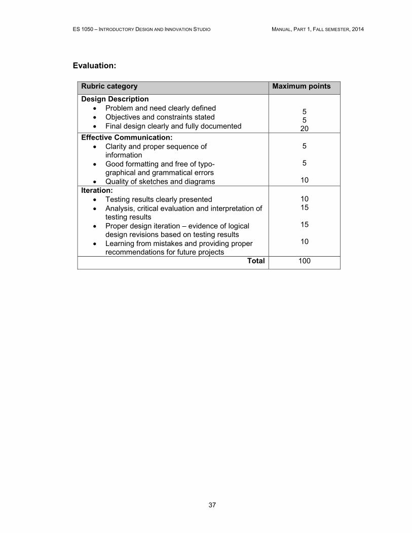
Evaluation:
Rubric category Maximum points
Design Description
• Problem and need clearly defined • Objectives and constraints stated • Final design clearly and fully documented
5 5 20
Effective Communication:
• Clarity and proper sequence of information
• Good formatting and free of typo- graphical and grammatical errors
• Quality of sketches and diagrams
5
5
10
Iteration:
• Testing results clearly presented • Analysis, critical evaluation and interpretation of
testing results • Proper design iteration – evidence of logical
design revisions based on testing results • Learning from mistakes and providing proper
recommendations for future projects
10 15
15
10
Total 100
ES 1050 – INTRODUCTORY DESIGN AND INNOVATION STUDIO MANUAL, PART 1, FALL SEMESTER, 2014
38
2.6 Interview Assignment
Requirements: The management of projects is a key component of the job of many practicing
Engineers. You are required to interview a practicing Engineer (may be an
EIT, but must have an engineering degree) who has worked in or is working
in the area of Project Management.
• The person cannot be a Professor or someone working at UWO (has to be
from outside).
• You can use phone, email or in-person approaches for the interview.
• The person can be working in any discipline in any field including industry,
government or non-profit organizations. They may be working anywhere in
the world.
• You can use your contacts (family, friends, Professors, others) to connect you
with this person or you can “cold-call”. The subject of your interview may be
a family member.
• The deliverable is a report based on the interview. The report should not be
merely a transcript of the interview, but should rather address the following
areas:
o The engineering background and field in which the person works
(provide contact information).
o The project management tools used (if any) and approaches used for
managing projects (by the person you talk to).
o The significance and importance of teams (if any). E.g. were projects
done in teams, what was the composition of the teams, how effective
were they?
o The way you went about setting up the interview and how you
prepared for it.
o The report should be typewritten using proper English grammar and
syntax, be free from errors and read well. The report should not
exceed 1500 words.
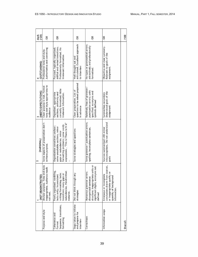
• The report will be marked using the rubric on the next page.
Due December 1, 2014
ES 1050 – INTRODUCTORY DESIGN AND INNOVATION STUDIO MANUAL, PART 1, FALL SEMESTER, 2014
39
ES 1050 – INTRODUCTORY DESIGN AND INNOVATION STUDIO MANUAL, PART 1, FALL SEMESTER, 2014
40
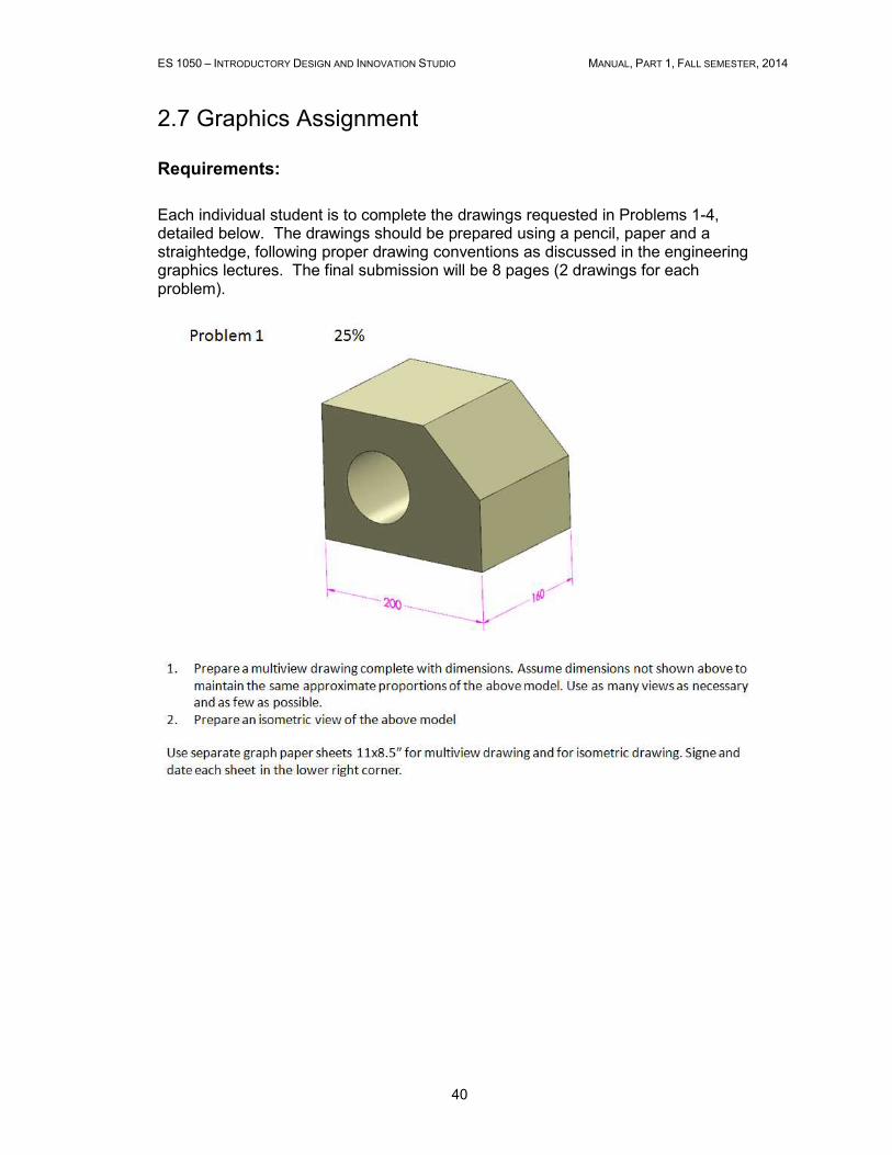
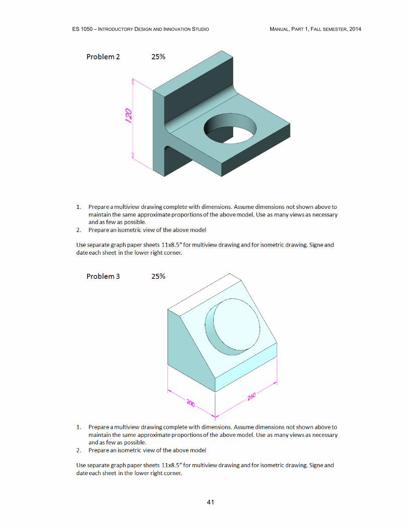
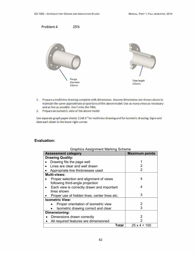
2.7 Graphics Assignment Requirements:
Each individual student is to complete the drawings requested in Problems 1-4, detailed below. The drawings should be prepared using a pencil, paper and a straightedge, following proper drawing conventions as discussed in the engineering graphics lectures. The final submission will be 8 pages (2 drawings for each problem).
ES 1050 – INTRODUCTORY DESIGN AND INNOVATION STUDIO MANUAL, PART 1, FALL SEMESTER, 2014
41
ES 1050 – INTRODUCTORY DESIGN AND INNOVATION STUDIO MANUAL, PART 1, FALL SEMESTER, 2014
42
Evaluation:
Graphics Assignment Marking Scheme Assessment category Maximum points
Drawing Quality:
• Drawing fits the page well • Lines are clear and well drawn • Appropriate line thicknesses used
1 2 2
Multi-views:
• Proper selection and alignment of views following third-angle projection
• Each view is correctly drawn and important lines shown
• Proper use of hidden lines, center lines etc.
4
4
3
Isometric View:
• Proper orientation of isometric view • Isometric drawing correct and clear
2 3
Dimensioning:
• Dimensions drawn correctly • All required features are dimensioned
2 2
Total 25 x 4 = 100
ES 1050 – INTRODUCTORY DESIGN AND INNOVATION STUDIO MANUAL, PART 1, FALL SEMESTER, 2014
43
2.8 Mark Breakdown, Fall Semester 2014
Design Project I Prob. Def and Concept List 5
Sketch 5
Final Report 20
Presentation 5 Total DP I 35
Design Project II
Performance 12
Critique 3
Report 15
Total DP II 30
Tests and Assignments
Graphics Assignment 10
Interview Assignment 10
Total T & A 20
Notebook (submitted end of fall term) 5
Total Fall Term 90

ES 1050 – INTRODUCTORY DESIGN AND INNOVATION STUDIO MANUAL, PART 1, FALL SEMESTER, 2014
44
Chapter 3
Examples
3.1 Design notebook
ES 1050 – INTRODUCTORY DESIGN AND INNOVATION STUDIO MANUAL, PART 1, FALL SEMESTER, 2014
45
ES 1050 – INTRODUCTORY DESIGN AND INNOVATION STUDIO MANUAL, PART 1, FALL SEMESTER, 2014
46
ES 1050 – INTRODUCTORY DESIGN AND INNOVATION STUDIO MANUAL, PART 1, FALL SEMESTER, 2014
47
ES 1050 – INTRODUCTORY DESIGN AND INNOVATION STUDIO MANUAL, PART 1, FALL SEMESTER, 2014
48
ES 1050 – INTRODUCTORY DESIGN AND INNOVATION STUDIO MANUAL, PART 1, FALL SEMESTER, 2014
49
ES 1050 – INTRODUCTORY DESIGN AND INNOVATION STUDIO MANUAL, PART 1, FALL SEMESTER, 2014
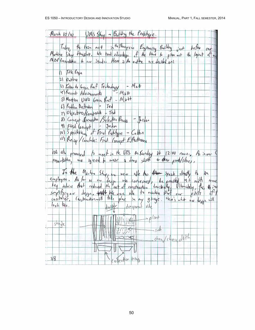
50

ES 1050 – INTRODUCTORY DESIGN AND INNOVATION STUDIO MANUAL, PART 1, FALL SEMESTER, 2014
51
3.2 Interview assignment
ES 1050 – INTRODUCTORY DESIGN AND INNOVATION STUDIO MANUAL, PART 1, FALL SEMESTER, 2014
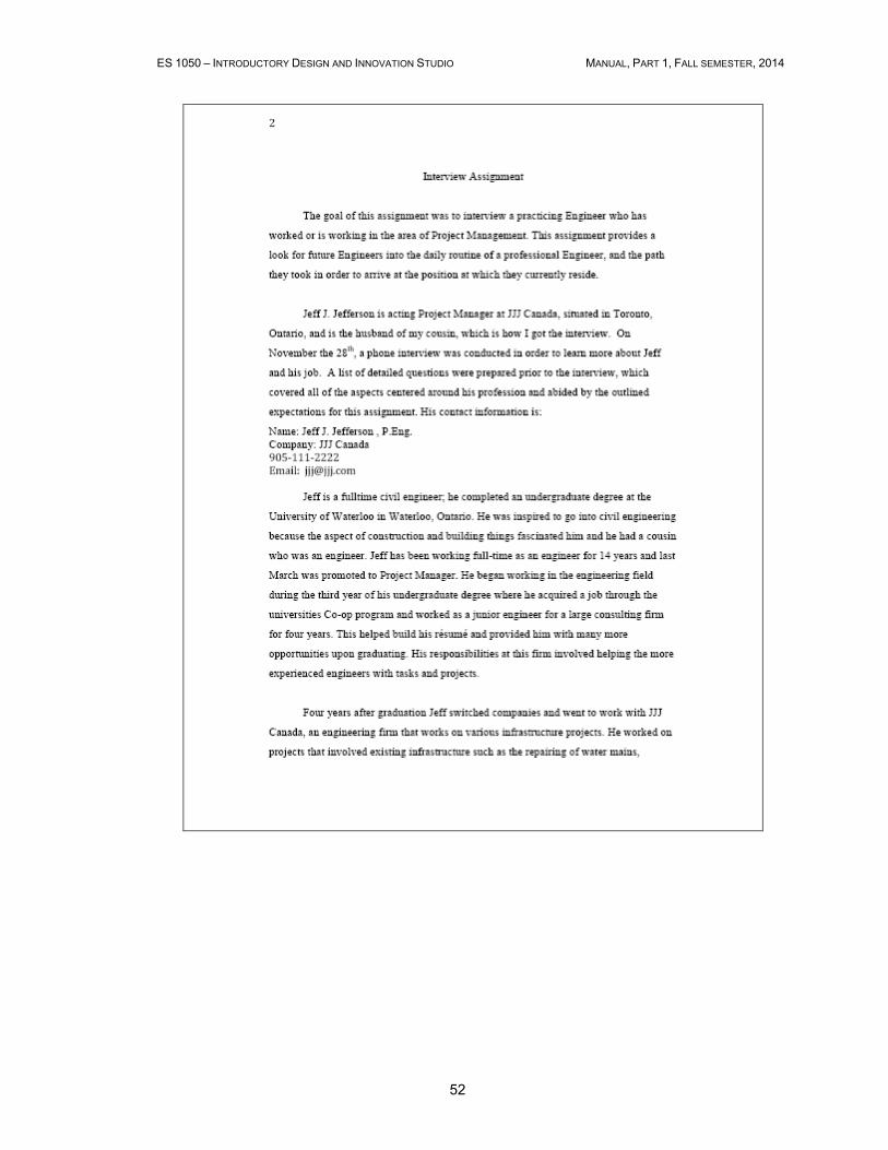
52
ES 1050 – INTRODUCTORY DESIGN AND INNOVATION STUDIO MANUAL, PART 1, FALL SEMESTER, 2014
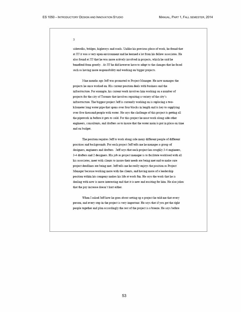
53
ES 1050 – INTRODUCTORY DESIGN AND INNOVATION STUDIO MANUAL, PART 1, FALL SEMESTER, 2014
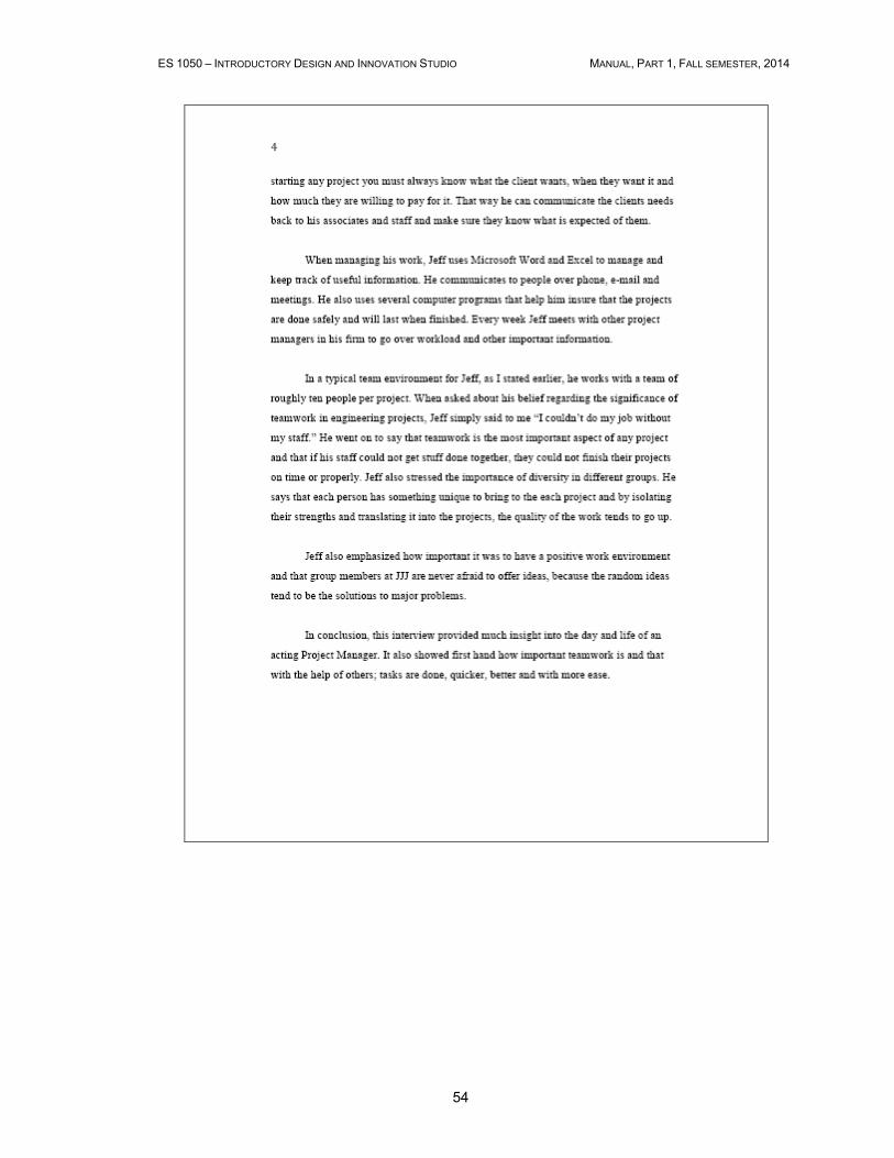
54
ES 1050 – INTRODUCTORY DESIGN AND INNOVATION STUDIO MANUAL, PART 1, FALL SEMESTER, 2014
55

ES 1050 – INTRODUCTORY DESIGN AND INNOVATION STUDIO MANUAL, PART 1, FALL SEMESTER, 2014
56
3.3 Design Project I report

ES 1050 – INTRODUCTORY DESIGN AND INNOVATION STUDIO MANUAL, PART 1, FALL SEMESTER, 2014
57

ES 1050 – INTRODUCTORY DESIGN AND INNOVATION STUDIO MANUAL, PART 1, FALL SEMESTER, 2014
58

ES 1050 – INTRODUCTORY DESIGN AND INNOVATION STUDIO MANUAL, PART 1, FALL SEMESTER, 2014
59

ES 1050 – INTRODUCTORY DESIGN AND INNOVATION STUDIO MANUAL, PART 1, FALL SEMESTER, 2014
60

ES 1050 – INTRODUCTORY DESIGN AND INNOVATION STUDIO MANUAL, PART 1, FALL SEMESTER, 2014
61
ES 1050 – INTRODUCTORY DESIGN AND INNOVATION STUDIO MANUAL, PART 1, FALL SEMESTER, 2014
62
ES 1050 – INTRODUCTORY DESIGN AND INNOVATION STUDIO MANUAL, PART 1, FALL SEMESTER, 2014
63

ES 1050 – INTRODUCTORY DESIGN AND INNOVATION STUDIO MANUAL, PART 1, FALL SEMESTER, 2014
64
ES 1050 – INTRODUCTORY DESIGN AND INNOVATION STUDIO MANUAL, PART 1, FALL SEMESTER, 2014
65
ES 1050 – INTRODUCTORY DESIGN AND INNOVATION STUDIO MANUAL, PART 1, FALL SEMESTER, 2014
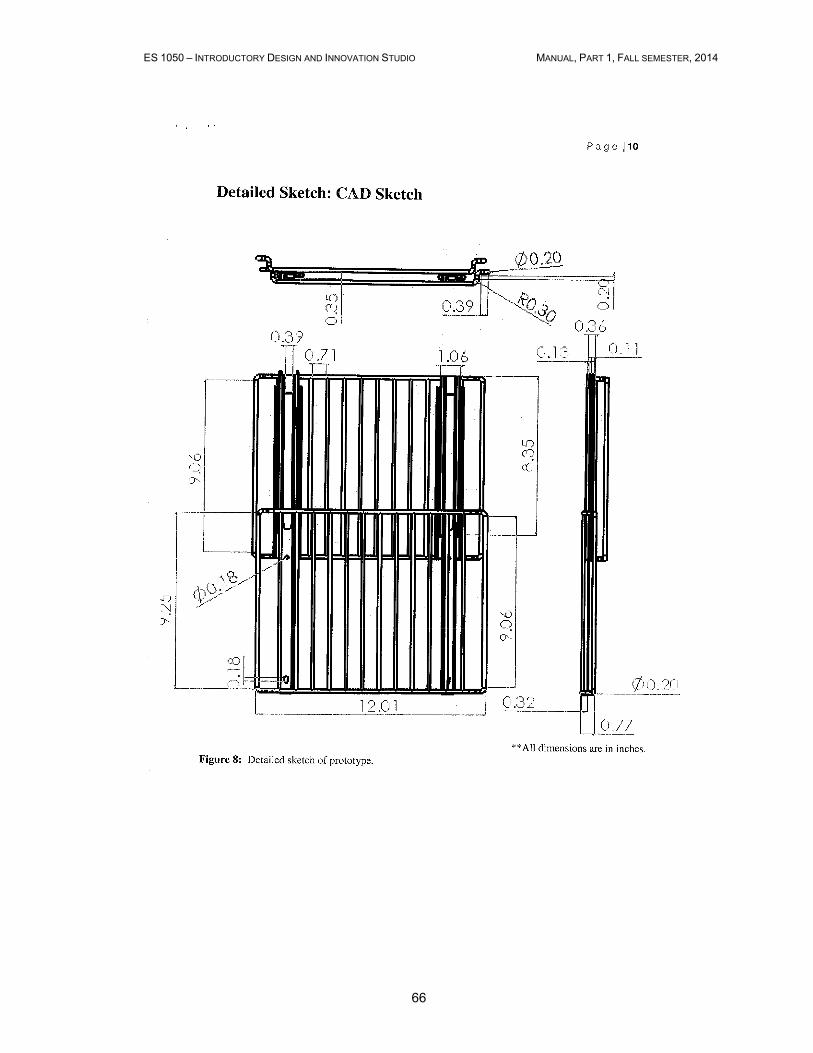
66
ES 1050 – INTRODUCTORY DESIGN AND INNOVATION STUDIO MANUAL, PART 1, FALL SEMESTER, 2014
67
ES 1050 – INTRODUCTORY DESIGN AND INNOVATION STUDIO MANUAL, PART 1, FALL SEMESTER, 2014
68

ES 1050 – INTRODUCTORY DESIGN AND INNOVATION STUDIO MANUAL, PART 1, FALL SEMESTER, 2014
69

ES 1050 – INTRODUCTORY DESIGN AND INNOVATION STUDIO MANUAL, PART 1, FALL SEMESTER, 2014
70

ES 1050 – INTRODUCTORY DESIGN AND INNOVATION STUDIO MANUAL, PART 1, FALL SEMESTER, 2014
71
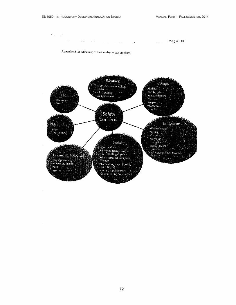
ES 1050 – INTRODUCTORY DESIGN AND INNOVATION STUDIO MANUAL, PART 1, FALL SEMESTER, 2014
72
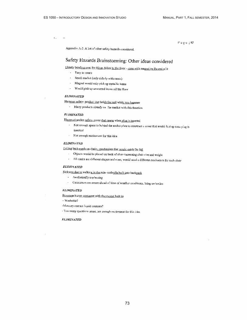
ES 1050 – INTRODUCTORY DESIGN AND INNOVATION STUDIO MANUAL, PART 1, FALL SEMESTER, 2014
73
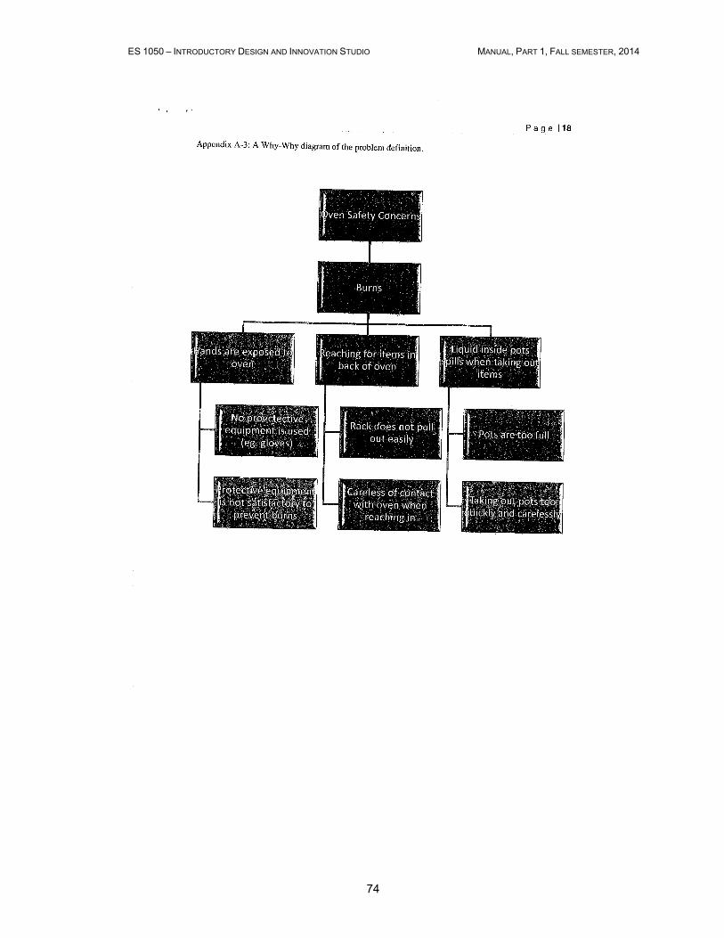
ES 1050 – INTRODUCTORY DESIGN AND INNOVATION STUDIO MANUAL, PART 1, FALL SEMESTER, 2014
74
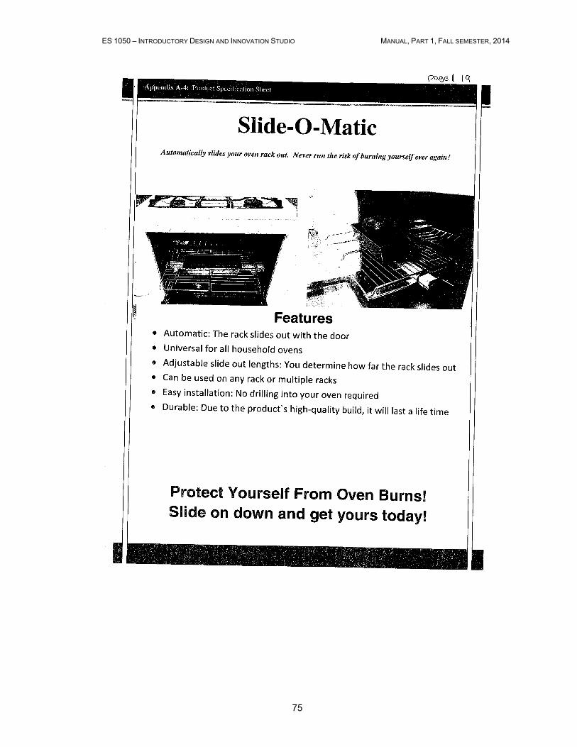
ES 1050 – INTRODUCTORY DESIGN AND INNOVATION STUDIO MANUAL, PART 1, FALL SEMESTER, 2014
75
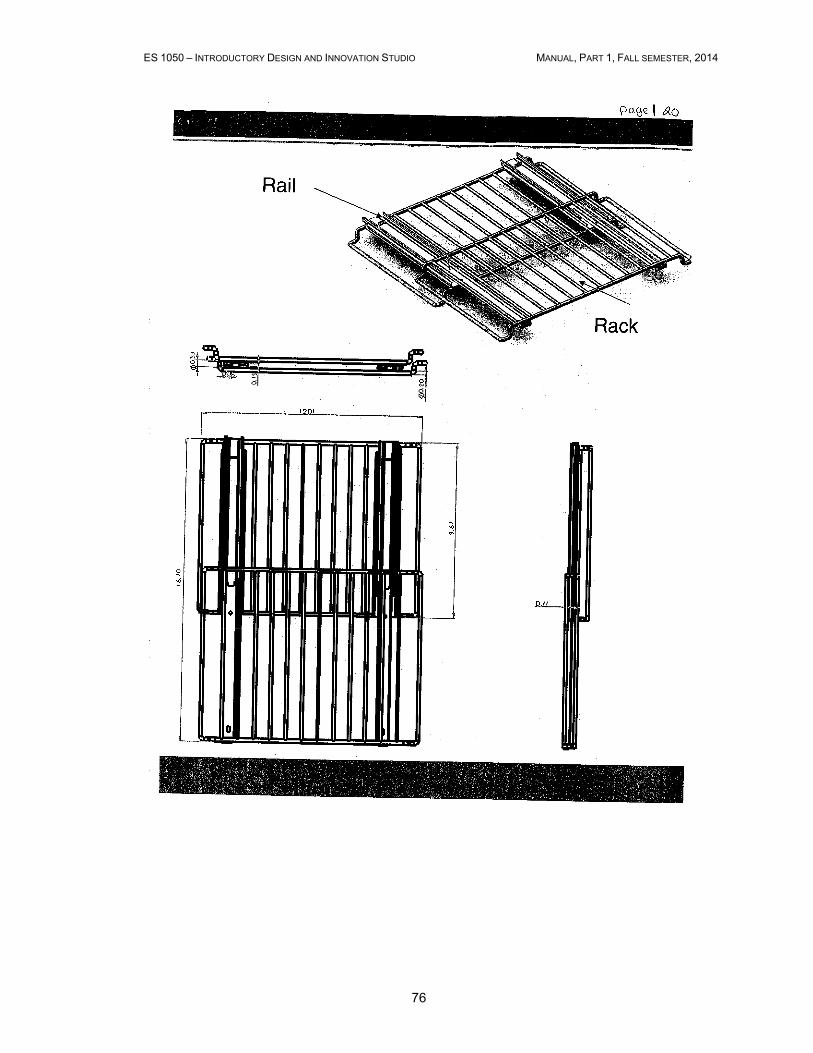
ES 1050 – INTRODUCTORY DESIGN AND INNOVATION STUDIO MANUAL, PART 1, FALL SEMESTER, 2014
76

ES 1050 – INTRODUCTORY DESIGN AND INNOVATION STUDIO MANUAL, PART 1, FALL SEMESTER, 2014
77
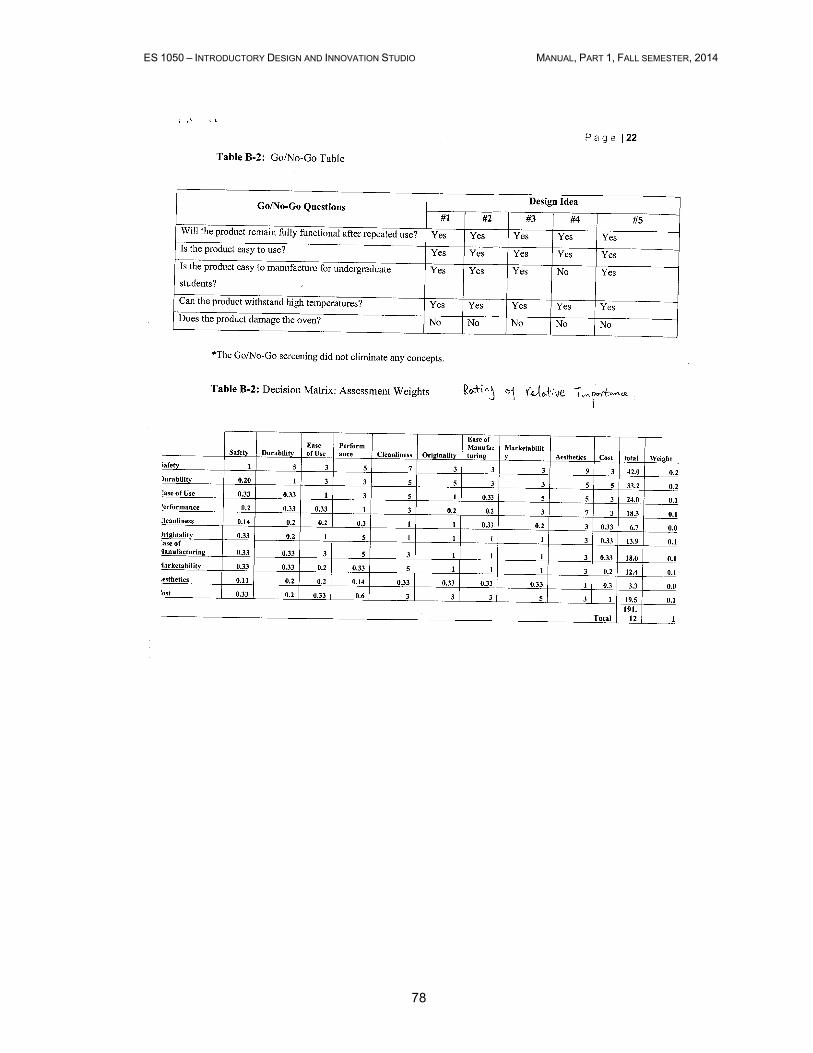
ES 1050 – INTRODUCTORY DESIGN AND INNOVATION STUDIO MANUAL, PART 1, FALL SEMESTER, 2014
78
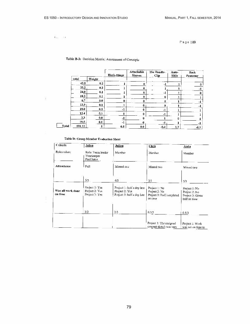
ES 1050 – INTRODUCTORY DESIGN AND INNOVATION STUDIO MANUAL, PART 1, FALL SEMESTER, 2014
79
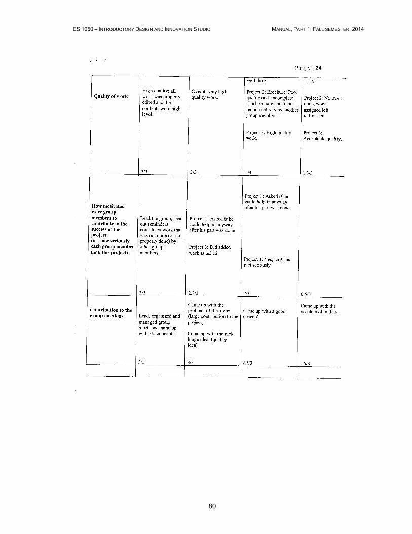
ES 1050 – INTRODUCTORY DESIGN AND INNOVATION STUDIO MANUAL, PART 1, FALL SEMESTER, 2014
80
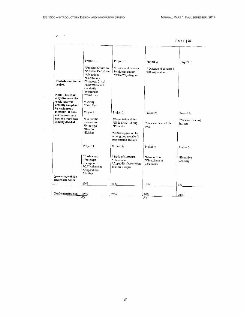
ES 1050 – INTRODUCTORY DESIGN AND INNOVATION STUDIO MANUAL, PART 1, FALL SEMESTER, 2014
81

ES 1050 – INTRODUCTORY DESIGN AND INNOVATION STUDIO MANUAL, PART 1, FALL SEMESTER, 2014
82
3.4 Design Project II report

ES 1050 – INTRODUCTORY DESIGN AND INNOVATION STUDIO MANUAL, PART 1, FALL SEMESTER, 2014
83
ES 1050 – INTRODUCTORY DESIGN AND INNOVATION STUDIO MANUAL, PART 1, FALL SEMESTER, 2014
84
ES 1050 – INTRODUCTORY DESIGN AND INNOVATION STUDIO MANUAL, PART 1, FALL SEMESTER, 2014
85
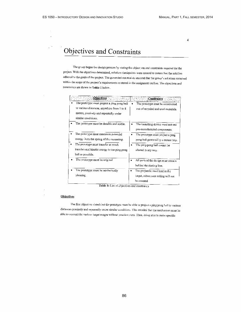
ES 1050 – INTRODUCTORY DESIGN AND INNOVATION STUDIO MANUAL, PART 1, FALL SEMESTER, 2014
86
ES 1050 – INTRODUCTORY DESIGN AND INNOVATION STUDIO MANUAL, PART 1, FALL SEMESTER, 2014
87

ES 1050 – INTRODUCTORY DESIGN AND INNOVATION STUDIO MANUAL, PART 1, FALL SEMESTER, 2014
88

ES 1050 – INTRODUCTORY DESIGN AND INNOVATION STUDIO MANUAL, PART 1, FALL SEMESTER, 2014
89

ES 1050 – INTRODUCTORY DESIGN AND INNOVATION STUDIO MANUAL, PART 1, FALL SEMESTER, 2014
90

ES 1050 – INTRODUCTORY DESIGN AND INNOVATION STUDIO MANUAL, PART 1, FALL SEMESTER, 2014
91

ES 1050 – INTRODUCTORY DESIGN AND INNOVATION STUDIO MANUAL, PART 1, FALL SEMESTER, 2014
92

ES 1050 – INTRODUCTORY DESIGN AND INNOVATION STUDIO MANUAL, PART 1, FALL SEMESTER, 2014
93

ES 1050 – INTRODUCTORY DESIGN AND INNOVATION STUDIO MANUAL, PART 1, FALL SEMESTER, 2014
94
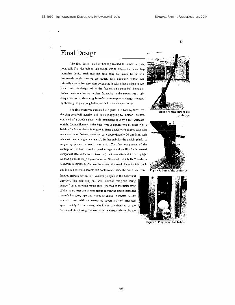
ES 1050 – INTRODUCTORY DESIGN AND INNOVATION STUDIO MANUAL, PART 1, FALL SEMESTER, 2014
95
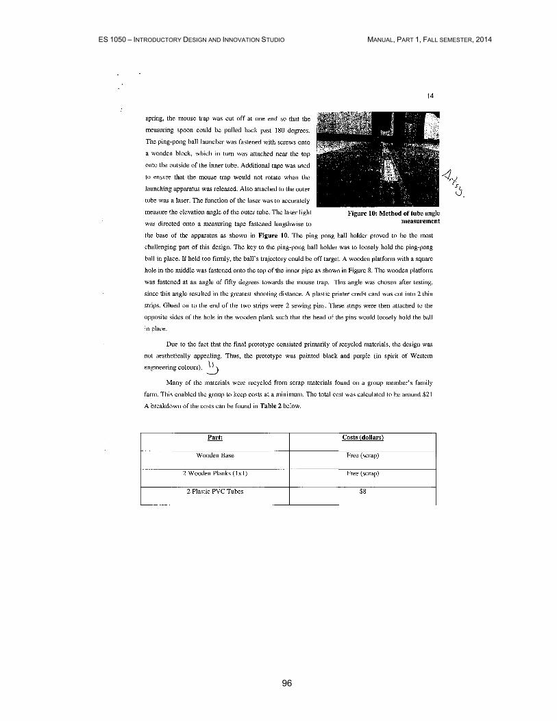
ES 1050 – INTRODUCTORY DESIGN AND INNOVATION STUDIO MANUAL, PART 1, FALL SEMESTER, 2014
96
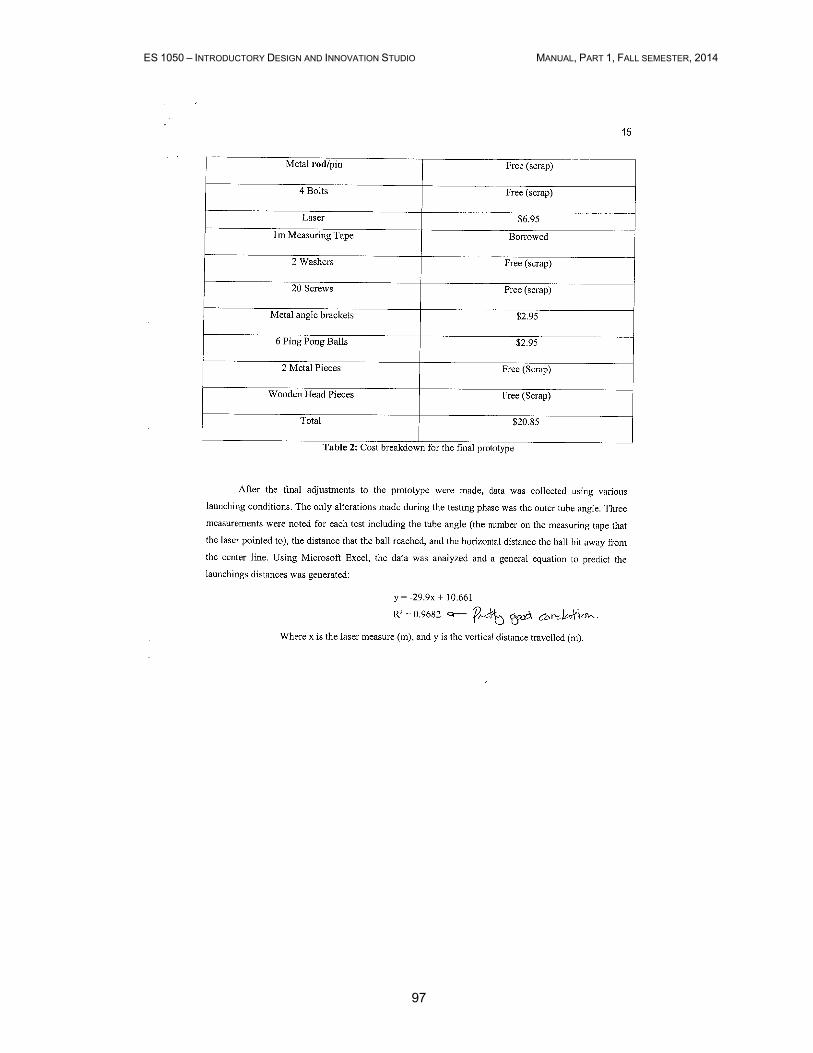
ES 1050 – INTRODUCTORY DESIGN AND INNOVATION STUDIO MANUAL, PART 1, FALL SEMESTER, 2014
97
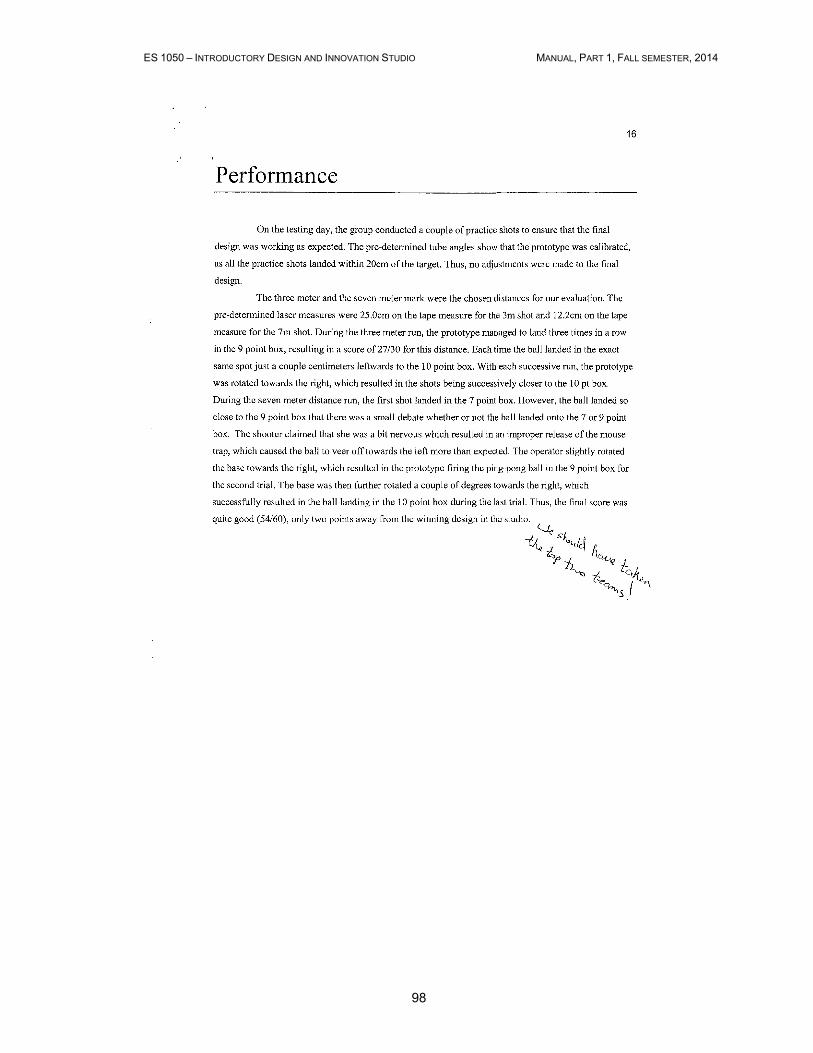
ES 1050 – INTRODUCTORY DESIGN AND INNOVATION STUDIO MANUAL, PART 1, FALL SEMESTER, 2014
98
ES 1050 – INTRODUCTORY DESIGN AND INNOVATION STUDIO MANUAL, PART 1, FALL SEMESTER, 2014
99

ES 1050 – INTRODUCTORY DESIGN AND INNOVATION STUDIO MANUAL, PART 1, FALL SEMESTER, 2014
100
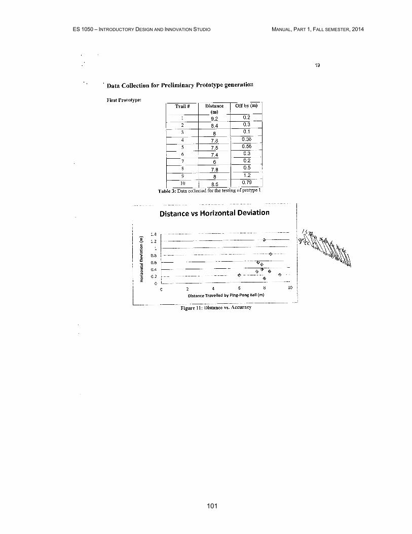
ES 1050 – INTRODUCTORY DESIGN AND INNOVATION STUDIO MANUAL, PART 1, FALL SEMESTER, 2014
101
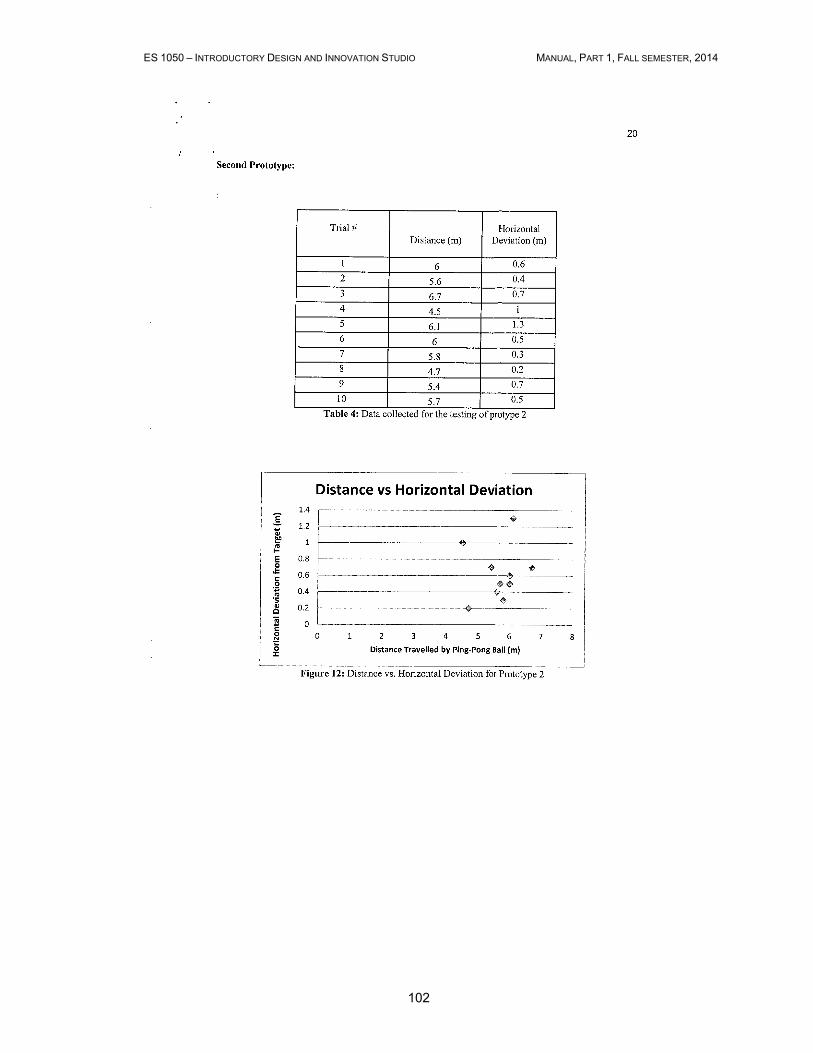
ES 1050 – INTRODUCTORY DESIGN AND INNOVATION STUDIO MANUAL, PART 1, FALL SEMESTER, 2014
102

ES 1050 – INTRODUCTORY DESIGN AND INNOVATION STUDIO MANUAL, PART 1, FALL SEMESTER, 2014
103

ES 1050 – INTRODUCTORY DESIGN AND INNOVATION STUDIO MANUAL, PART 1, FALL SEMESTER, 2014
104
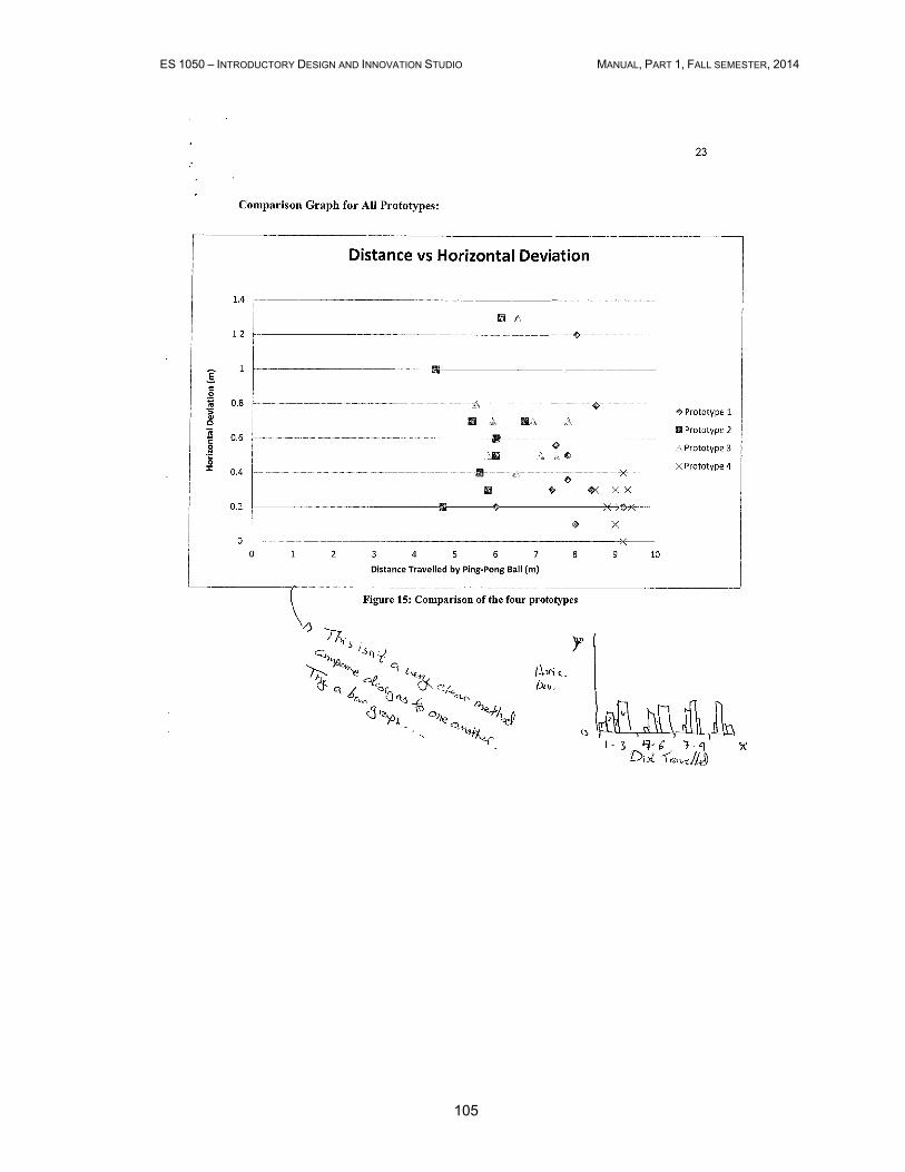
ES 1050 – INTRODUCTORY DESIGN AND INNOVATION STUDIO MANUAL, PART 1, FALL SEMESTER, 2014
105
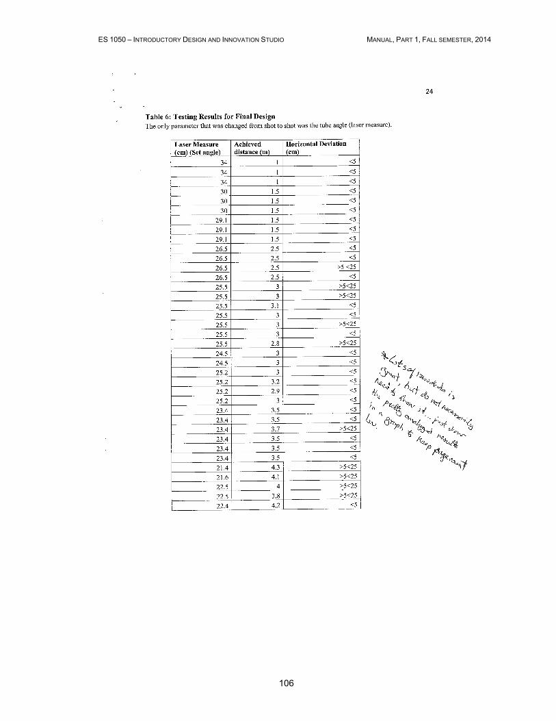
ES 1050 – INTRODUCTORY DESIGN AND INNOVATION STUDIO MANUAL, PART 1, FALL SEMESTER, 2014
106
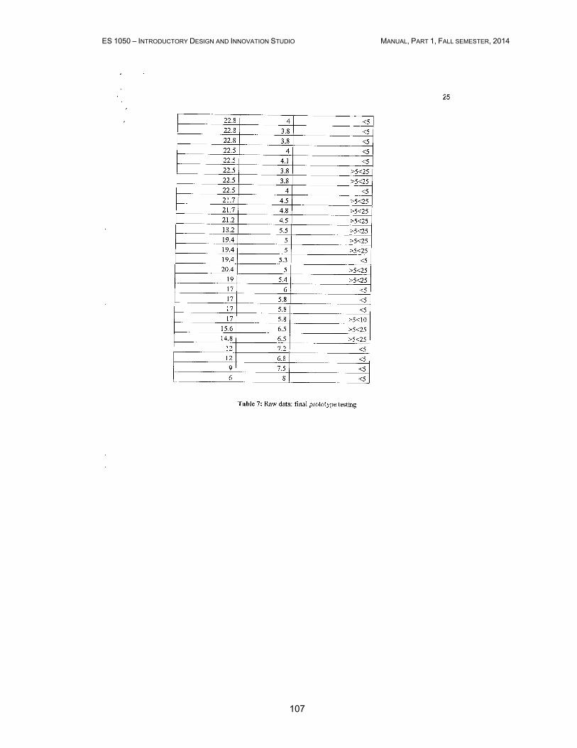
ES 1050 – INTRODUCTORY DESIGN AND INNOVATION STUDIO MANUAL, PART 1, FALL SEMESTER, 2014
107

ES 1050 – INTRODUCTORY DESIGN AND INNOVATION STUDIO MANUAL, PART 1, FALL SEMESTER, 2014
108
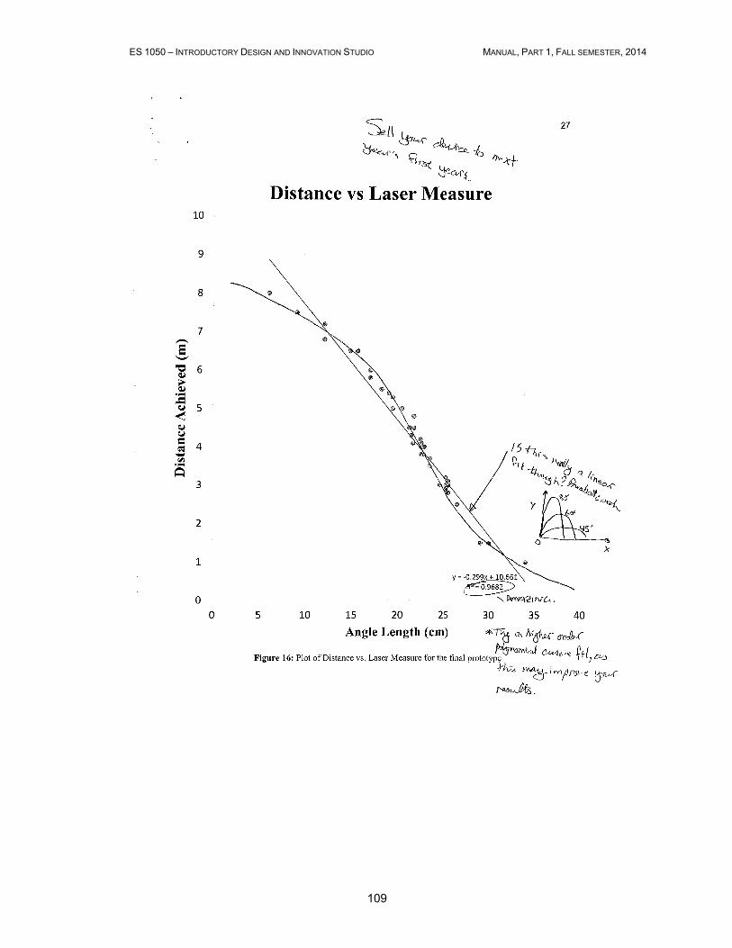
ES 1050 – INTRODUCTORY DESIGN AND INNOVATION STUDIO MANUAL, PART 1, FALL SEMESTER, 2014
109
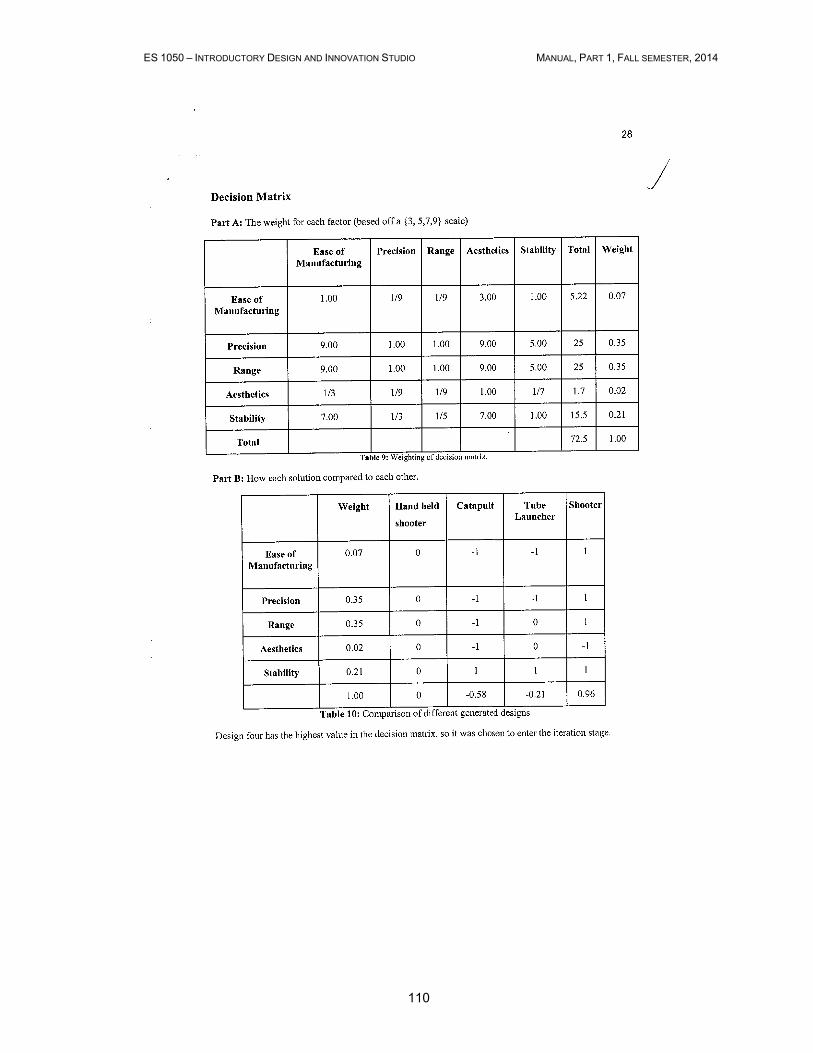
ES 1050 – INTRODUCTORY DESIGN AND INNOVATION STUDIO MANUAL, PART 1, FALL SEMESTER, 2014
110
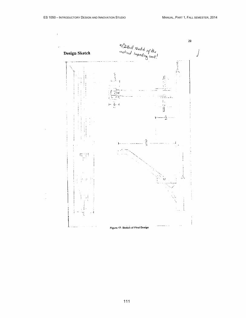
ES 1050 – INTRODUCTORY DESIGN AND INNOVATION STUDIO MANUAL, PART 1, FALL SEMESTER, 2014
111

ES 1050 – INTRODUCTORY DESIGN AND INNOVATION STUDIO MANUAL, PART 1, FALL SEMESTER, 2014
112

ES 1050 – INTRODUCTORY DESIGN AND INNOVATION STUDIO MANUAL, PART 1, FALL SEMESTER, 2014
113
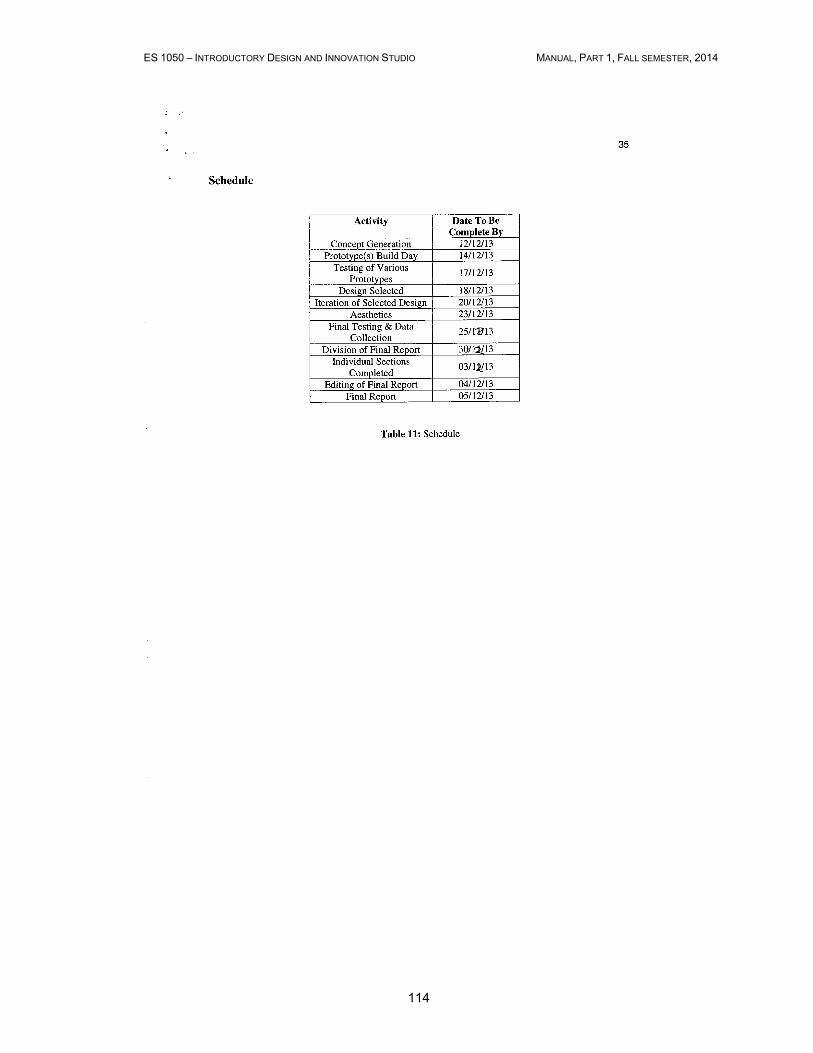
ES 1050 – INTRODUCTORY DESIGN AND INNOVATION STUDIO MANUAL, PART 1, FALL SEMESTER, 2014
114
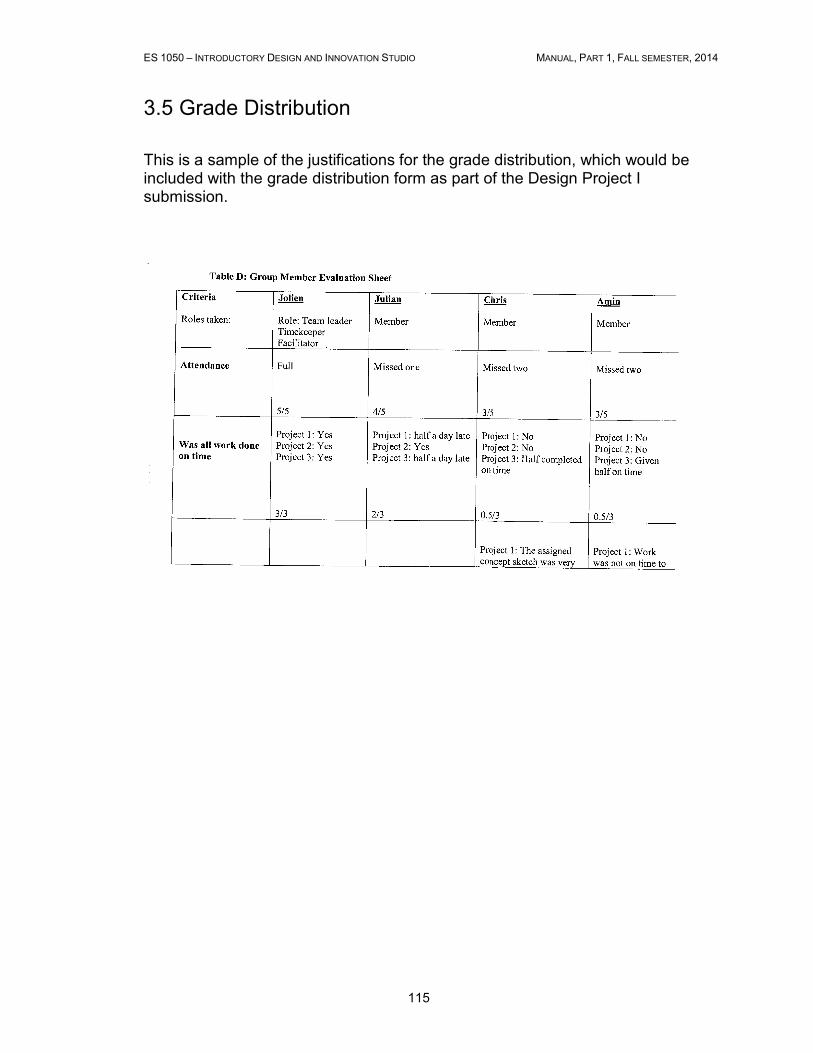
ES 1050 – INTRODUCTORY DESIGN AND INNOVATION STUDIO MANUAL, PART 1, FALL SEMESTER, 2014
115
3.5 Grade Distribution
This is a sample of the justifications for the grade distribution, which would be included with the grade distribution form as part of the Design Project I submission.
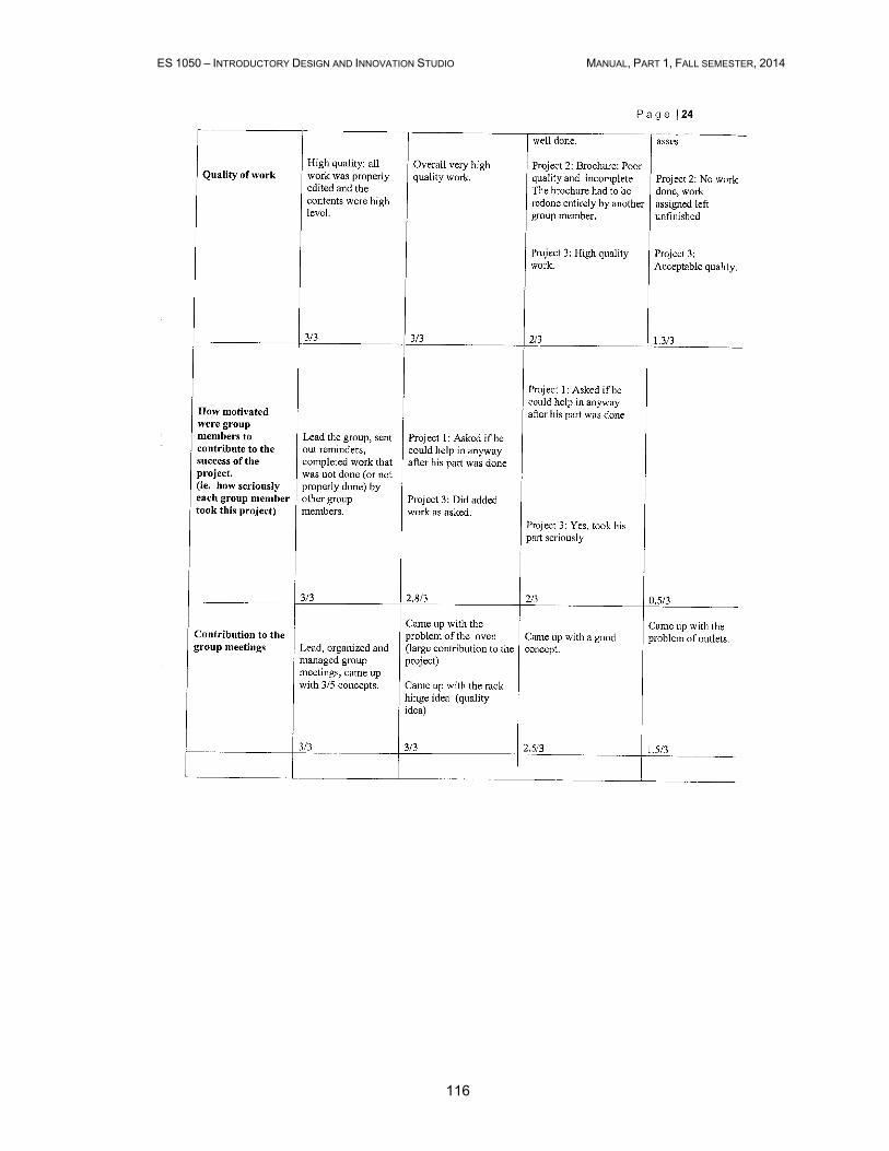
ES 1050 – INTRODUCTORY DESIGN AND INNOVATION STUDIO MANUAL, PART 1, FALL SEMESTER, 2014
116

ES 1050 – INTRODUCTORY DESIGN AND INNOVATION STUDIO MANUAL, PART 1, FALL SEMESTER, 2014
117
ES 1050 – INTRODUCTORY DESIGN AND INNOVATION STUDIO MANUAL, PART 1, FALL SEMESTER, 2014
118
Chapter 4
Course Necessary Tools
4.1 SolidWorks
SOLIDWORKS is solid modeling CAD (Computer Aided Design) software that runs
on Microsoft Windows and is produced by Dassault Systèmes SolidWorks Corp., a
subsidiary of Dassault Systèmes, S. A. SolidWorks is currently used by over 2 million
engineers and designers at more than 165,000 companies worldwide.
History briefly
SolidWorks Corporation was founded in December 1993 by Massachusetts Institute
of Technology graduate Jon Hirschtick. Hirschtick used $1 million he had made while
a member of the MIT Blackjack Team to set up the company. Initially based in
Waltham, Massachusetts, USA, Hirschtick recruited a team of engineers with the
goal of building 3D CAD software that was easy-to-use, affordable, and available on
the Windows desktop. Operating later from Concord, Massachusetts, SolidWorks
released its first product SolidWorks 95, in 1995. In 1997 Dassault, best known for its
CATIA CAD software, acquired SolidWorks for $310 million in stock.
Why engineers use SOLIDWORKS
SOLIDWORKS offers complete 3D software tools that let you create, simulate,
publish, and manage your data. SOLIDWORKS products are easy to learn and use;
they work together to help you design products better, faster, and more cost-
effectively. The SOLIDWORKS focus on ease-of-use allows more engineers,
designers and other technology professionals than ever before to take advantage of
3D in bringing their designs to life.
SOLIDWORKS in ES1050 Design Projects
SOLIDWORKS program is installed in all computer labs available to ES1050
students. SOLIDWORKS CAD software is not used in DPI and DPII; the use of
SOLIDWORKS in DPIII is optional. You are expected to learn this program on your
own. Consult with your studio instructor prior to implementing SOLIDWORKS as a
design tool in DPIII.
Use these links for more information about SOLIDWORKS:
http://en.wikipedia.org/wiki/SolidWorks
http://www.solidworks.com/sw/products/3d-cad/packages.htm
http://my.solidworks.com/
http://www.solidworks.com/sw/resources.htm
http://help.solidworks.com/HelpProducts.aspx
ES 1050 – INTRODUCTORY DESIGN AND INNOVATION STUDIO MANUAL, PART 1, FALL SEMESTER, 2014
119
4.2 Microsoft Excel
The spreadsheet program most widely used in engineering is Microsoft Excel. A spreadsheet is a rectangular grid composed of addressable units - cells. A cell is addressed by referencing its column and row numbers. Spreadsheet computer programs were initially designed to make simple operations on large amounts of data easy and to be used for financial planning, record keeping and calculations. History briefly Electronic spreadsheet software came to existence in 1978 when Harvard Business School student Dan Bricklin developed a program called VisiCalc. It was a relatively small program with a few basic capabilities. The program became fast and got better arithmetic. A million copies of the program were sold. In early 80s Microsoft jumped into the market of electronic spreadsheets with its product MultiPlan. In middle 80s Microsoft released another spreadsheet product: Excel. Why engineers use Excel Over time more functions/features have been added to spreadsheet application programs. Currently Excel includes variety of special features and tools that can be used to solve many of the problems that typically arise in engineering data processing and analysis. The ability to import, export, store, process and sort data, manipulate formulas, arrays and mathematical functions, to display data in various graphical formats and to test and refine potential solutions to a problem under consideration makes Excel one of the common, well-armed and valuable modern-day tools of practicing engineers. Excel in DP II ES 1050 students are expected to use MS Excel (or alternatively Matlab) to organize and analyze the results of prototype testing during the Design Project II. Many first year engineering students are familiar with spreadsheet computer programs and applied them to present data or make simple calculations. The 1050 Design Project II requires the quantitative analysis of data gained during the prototype testing for use in optimizing your design. Students are encouraged to present the results of quantitative analysis of data set including the bivariate regression (between 2 variables x and y that you measured during the prototype testing phase) to establish a mathematical relationship between variables and to calculate a correlation coefficient showing the strength of a relationship between them. For more information of Excel, you are encouraged to consult the Excel User’s guide, or on-line tutorials such as:
• http://www.gcflearnfree.org/office
• http://office.microsoft.com/en-001/excel-help/training-courses-for-excel-2013-HA104032083.aspx
• http://chandoo.org/wp/excel-tutorial/
• http://www.internet4classrooms.com/on-line_excel.htm
or text books describing its use, for example: Byron Gottfried, Spreadsheet Tools for Engineers using Excel (Mcgraw-Hill's Best--Basic Engineering Series and Tools), McGraw-Hill Science/Engineering/Math ©2005, ISBN:0072971843, Edition 3rd.
ES 1050 – INTRODUCTORY DESIGN AND INNOVATION STUDIO MANUAL, PART 1, FALL SEMESTER, 2014
120
4.3 Matlab
Matlab (Short for Matrix Laboratory) is a mathematical computation tool, which is
used extensively by engineers and researchers in solving technical problems. It is a
good choice for repetitive calculations and processing of large number of data.
Matlab is a preferred tool in calculations involved matrices. Data acquisition, signal
processing, statistics, optimization and image processing are main features of
Matlab.
Although Matlab was originally adopted by engineers in the field of signal processing
and electrical engineering, it had been through a number of modifications to extend
its application in a wide range of disciplines.
Matlab uses the standard algebraic rules for order of operations. Matlab has an
extensive library of built-in mathematical functions, some of which are:
• General mathematical functions such as exponential functions,
logarithmic functions etc.
• standard trigonometric functions, inverse trigonometric functions,
hyperbolic trigonometric functions, etc,
• Rounding functions
• Functions used in discrete mathematics such as factoring functions,
prime number functions etc.
• Data analysis functions
• Functions used with complex numbers
• Statistical analysis functions etc.
These functions can be easily recalled in programs used for specific engineering
problems. You can also create your own functions in Matlab.
Another important feature of Matlab is creation and labeling of two and three
dimensional plots.
Matlab is available in all computer labs located in the faculty of engineering at
Western.
Students can use Matlb for their assignments and data analysis for the second and
final design projects.

ES 1050 – INTRODUCTORY DESIGN AND INNOVATION STUDIO MANUAL, PART 1, FALL SEMESTER, 2014
121
4.4 Manufacturing and Student Shop Resources