Embed Size (px)
Citation preview

1. (d)
2. (b)
3. (c)
4. (b)
5. (b)
6. (c)
7. (c)
8. (b)
9. (b)
10. (b)
11. (c)
12. (d)
13. (c)
14. (d)
15. (a)
16. (c)
17. (c)
18. (a)
19. (c)
20. (b)
21. (d)
22. (c)
23. (a)
24. (b)
25. (a)
26. (a)
27. (b)
28. (a)
29. (d)
30. (a)
31. (c)
32. (b)
33. (c)
34. (b)
35. (a)
36. (d)
37. (c)
38. (b)
39. (c)
40. (b)
41. (d)
42. (c)
43. (b)
44. (a)
45. (b)
46. (d)
47. (d)
48. (c)
49. (d)
50. (b)
51. (d)
52. (a)
53. (b)
54. (a)
55. (b)
56. (c)
57. (c)
58. (a)
59. (a)
60. (a)
ESE-2018 PRELIMS TEST SERIESDate: 22 October, 2017
ANSWERS
61. (c)
62. (d)
63. (a)
64: (b)
65. (b)
66. (a)
67. (c)
68. (a)
69. (d)
70. (a)
71. (c)
72. (d)
73. (a)
74. (a)
75. (d)
76. (b)
77. (b)
78. (a)
79. (b)
80. (a)
81. (c)
82. (b)
83. (c)
84. (d)
85. (c)
86. (c)
87. (c)
88. (a)
89. (b)
90. (a)
91. (c)
92. (c)
93. (d)
94. (d)
95. (c)
96. (d)
97. (b)
98. (d)
99. (c)
100. (b)
101. (d)
102. (c)
103. (a)
104. (c)
105. (b)
106. (d)
107. (d)
108. (c)
109. (d)
110. (b)
111. (c)
112. (c)
113. (a)
114. (b)
115. (c)
116. (c)
117. (c)
118. (c)
119. (b)
120. (b)
121. (a)
122. (a)
123. (a)
124. (c)
125. (b)
126. (b)
127. (c)
128. (b)
129. (a)
130. (d)
131. (a)
132. (b)
133. (a)
134. (b)
135. (a)
136. (a)
137. (b)
138. (d)
139. (d)
140. (a)
141. (c)
142. (a)
143. (c)
144. (c)
145. (d)
146. (c)
147. (a)
148. (b)
149. (a)
150. (c)

1. (d)
tan =T
C
F 1000 1F 1732 3
=11 1, tan 30
3 3
2. (b)
Chip thickness ratio = depth of cut
chip thickness
If depth of cut is halved, then for chip thicknessratio to be same, the chip thickness should alsobe halved.
3. (c)4. (b)
Geneva mechanism translates a continuousrotation into an intermittent rotary motion. Therotating drive wheel has a pin that reaches into aslot of the driven wheel. The drive wheel also hasa raised circular blocked disc that locks the drivenwheel in position between steps. If driven wheelhas n slots, it advances by 360°/n per full rotationof the drive wheel. Intermitted linear motion fromrotary motion can also be obtained using generamechanism.
Thus, genera mechanisms may be used to driverotary indexing machine. It uses a continuouslyrotating driver to index the table through a partialrotation.
5. (b)6. (c)
2
sVtA
2
sVt kA
7. (c)When two streams of liquid metal do not fuseproperly then they form a defect known as coldshut.
8. (b)The extrusion is carried out in a high compressionenvironment in a fluid medium due to which crack
ESE-2018 PRELIMS TEST SERIES SolutionsDate: 22 October, 2017
formation is suppressed and leads to aphenomenon called pressure induced ductility
9. (b)
Power = I2R = V.I = 5×10⁴ W
Energy supplied = (5 × 104) × (10 × 10–3) = 500J
Energy required for fusion
= (3 × 10–8) × 6950 × 1050 × 103 = 218.9 J
melting = 218.9 100500
= 43.8%
10. (b)Trepanning can be used to make gun barrels.
11. (c)
Conditions for BUE formation -
(a) ductile material
(b) inadequate lubrication
(c) feed, velocity slightly low
12. (d)The effect of feed and depth of cut is less on toollife as compared to velocity. So n < 1.
13. (c)Material removal rate (MRR) = f × d × V
= 30.4 4 120 1060
= 3mm3200
sec.
Specific cutting energy = PowerMRR
Fc × V = 2 × 3200
Fc = 3200 N
14. (d)
VTn = C
nT2V16
= C

IES M
ASTER
(Test - 05)-22 October 2017 (3)
n 4n 1V T 2 = nVT
1 – 4n = 0
n = 14
15. (a)For maximum production rate -
T = c1 n T
n
n = 0.21
Tc = tool changing time = 90 seconds
T =1 0.21 90
0.21
= 338.6 seconds
16. (c)
0.009 mm0.004 mm
Upper deviation
= Max. size – Basic size
= – 0.04
Lower deviation = Min. size – basic size.
= –0.009
Fundamental deviation = min{Upper deviation,Lower deviation}
= –0.004mm
Tolerance = 0.009 – 0.004 = 0.005 mm
17. (c)
60º
Best size wire to measure dia, = p sec2 2
=0.5 sec 30º2
= 0.29 mm
18. (a)Angle turned when 1 pulse is sent = 5º.
360º angle turned (1 revolution) when 72 pulse issent.
72 pulse reslts into 30mm pitch
1 pulse results into 3072
= 0.42mm
BLU = 0.42 mm
19. (c)No. of revolution in 1 minute = 350 revolution
Feed in 1 revolution = 0.1 m
Feed =30.1 10 mm rev.
350
Feed per insert or tooth = 30.1 10 1 0.03mm
350 10
20. (b)(a) Thermit welding is carried by a mixture of
Aluminium and Fe3O4 is 8:3 ratio by volume.
(b) EBM is generally carried out in vaccumchamber.
21. (d)Merchant’s theory -
2 = 90º
= 90º + 10º – (2 × 20º) = 60º
22. (c)Heat generated = V × I = 20 × IHeat required = 10 × (Thickness × Width ×Welding speed)
= 10 × 8 × 4 × 10 = 3200 W
melting =Heat requiredHeat supplied
0.8 × 0.625 =320020 I
I = 320A
23. (a)S.F. = 0.87×10⁶ s/m2
Area of the sphere = 24 r ,
Volume = 34 r3

IES M
ASTER
(4) (Test - 05)-22 October 2017
Time =2
s
s
V KA
= 2D K
6
=23
6 250 100.87 106
= 1510.417
24. (b)To avoid aspiration effect of molten metal in thesprue, the profile must be parabolic i.e.
2
1
AA =
x ;h x
1A 2gx 600
x = 11.46 cm
2A4
=11.46 0.6989
12 11.46
A2 = 2.795 cm2
25. (a)26. (a)
Gas defects = Pin hole porosity, blow hole.
Cuts & washes = Due to improper ramming ofmoulds
Note: Gas defects can be removed by creatingvent holes.
27. (b)Phenol formaldehyde and dry silica sand mixtureis used for shell mould casting.
28. (a)Solidification time is higher in sphere and lesser
in cube because the value of VA
is minimum
for cube since for a given volume it has highestsurface area. Sphere has minimum surface area.
29. (d)Maximum interference
= Max. size of shaft – Min. size of hole
= 30.04 – 30.03
= 0.01 mm
30. (a)In ECM process, MRR is proportional to gramatomic weight of material, current density, thermalconductiv ity of electrolyte. It is inverselyproportional to distance between tool and work.
31. (c)Flexible Manufacturing system (FMS) is acomputer control system used for batchproduction. Random sequencing of part tomachines by FMS.
32. (b)
Punching force (P) = dt
= 10 3 420
= 39584.06 N
= 39.584 kN
33. (c)
Required Blank dia
(D) = 2d 4dh
D = 270 4 70 35
D = 121.24 mm
34. (b)35. (a)36. (d)
Independent variables are those aspect of aprocess over which the operator has direct controlEg: starting material (cast, annealed etc). Startinggeometry of workpiece (round, square Tool or diegeometry (Die angles etc).
Lubrication (Solid or liquid lubrication)
Starting temperature
Speed of operation
Amount of deformation
Dependent variably are those aspects whichdepends upon the selection of independentvariables.
e.g.,
– Force or power requirement
– Material properties (Softness increases whentemperature increases
IES M
ASTER
(Test - 05)-22 October 2017 (5)
– Exit or final temperature
– Nature of material flow
– Surface finish and precision
37. (c)
Sticking region
Sticking region
Force–x + x
Linear (sticking)
Exponential (sliding)
– Maximum forging force occurs at the centreof workpiece.
– Sticking region occurs near the central regionand its cross-section is circular in circularworkpiece and rectangular in rectangularworkpiece.
38. (b)Speed range of presses Speed (m/s)
Hydraulic press – 0.06 – 0.3
Screw press – 0.6 – 1.2
Mechanical press – 0.06 – 1.5
Gravity drop hammer – 3.6 – 4.8
Power drop hammer – 3 – 9
Counterblow hammer – 4.5 – 9
39. (c)Centre cracking occurs in following operation
• Wire or rod drawing
• Extrusions
• Tube extrusion
• Tube spinning
40. (b)Compound die: Different operation at singlestation in single stroke.
Progressive die: Different operation at differentstation in single stroke.
Transfer die: Different operation at different stationin different stroke.
41. (d)Forging – Compressive force
Wire drawing – Compressive and tensile force
Stretch forming – Tensile force
Bending – Spring back force
42. (c)43. (b)
n = x y x y
2 2
cos2
= 400 300 400 300
2 2
cos 2 × 45°
= 350 MPa
44. (a)Proof stress: Tensile test
Endurance limit: Fatigue test
Leaf spring: Beam of uniform strength
Modulus of rigidity: Torsion test
45. (b)
For a linearly elastic, isotropic and homogeneousmaterial, the number of elastic constants requiredto relate stress and strain is two i.e. two of thefour must be known.
E = 9KG2G 3K= =1 1 23K G
If the material is non-isotropic (anistropic) thenthe elastic modulii will vary with additional stressappearing since there is a coupling between shearstress and normal stress for an amisotropicmaterial.

IES M
ASTER
(6) (Test - 05)-22 October 2017
E, G, K and represent the elastic modulus,shear modulus, bulk modulus and poissons ratiorespectively of a linearly elastic, isotropic andhomogeneous material. To express the stress-strain relationship completely for this material; atleast two of the four must be known.
46. (d)
L
3L
3L
=L
=3
AB =23
LL / 2 3L2
47. (d)48. (c)49. (d)50. (b)
x =PE
y = zP
mE
r = x y zP 2PE mE
51. (d) V = decreasing
dMdx
= V = decreasing
52. (a)Bending moment at any transverse cross-sectionis the algebraic sum of the moment of all forceson either side of the section.
53. (b)MA = 0 = MD
MB =2
CwL M8
ME =2 2wL wL 0
8 8
EBA C D
2wL8
2wL8
Bending moment diagram
Maximum bending moment = 2wL
854. (a)55. (b)
w
x
Mx =2wx
2
Z =2bd
6
=MZ
=2
2
wxbd26
2bx d
3 = wx2
b =2
23w x
d
b x2
56. (c)
C = 310 1 10 3 1
3EI 3EI
= 403EI
57. (c)2ML
2EI =4wL
8EI
M =2wL
458. (a)
=p
TrI

IES M
ASTER
(Test - 05)-22 October 2017 (7)
T = pIr
For solid circular shaft
T = 4 3D 2 D
32 D 16
For hollow circular shaft
T =
4 4 2D d32 D
= 4 4D d
16D
solid
circular
TT
=4
4 4D
D d59. (a)
Bending stress at neutral axis = 0
Shear force at mid span = 0
hence state of stress will be
60. (a)
T
T
BB C C
45°
A D
F
=BB CCAB CD
Diagonal strain = FC CC cos45 CC cos45
CDAF ACcos45
= 2CCcos45CD
= 35 102 2
61. (c)
xyx
xyy
2
2
=3 3
3 3
4 10 3 103 10 6 10
62. (d)63. (a)
max cylindrical vessel =
Pd2t
max spherical vessel =
Pd4t
Ratio =
Pd2t 2Pd4t
64: (b)
1Rankine load
= 1 1
Euler load Crushing load
Rankine load = Euler load Crushing loadEuler load + Crushing load
= 1200 24001200 2400
= 1200 2400
3600
= 800 kN
65. (b)Axial compression = Bx
30 kN
10 m
60 kNAy
Ax
B
Bx
By
B y = 30 202 30 50kN
2 30
IES M
ASTER
(8) (Test - 05)-22 October 2017
tan =x
y
B34 B
34
= xB50
Bx =150 37.5kN
4
66. (a)Radius of curvature will be same for both thebars.
1
1
MI
= 1ER
& 2
2
MI
= 2ER
1
1
MEI
= 2
2
MEI
1
2
MM
= 1
2
II
1 2
2 1
M I1
M I …(i)
Now,
max top stressmax bottom stress
=
11
1 1
222
2
M ×yI
M yI
1
2
= 1 2 1
2 1 2
M I yM I y
Using (i) 1
2
= 1
2
yy
1
2
=
t 23t 2
1
2
=
13
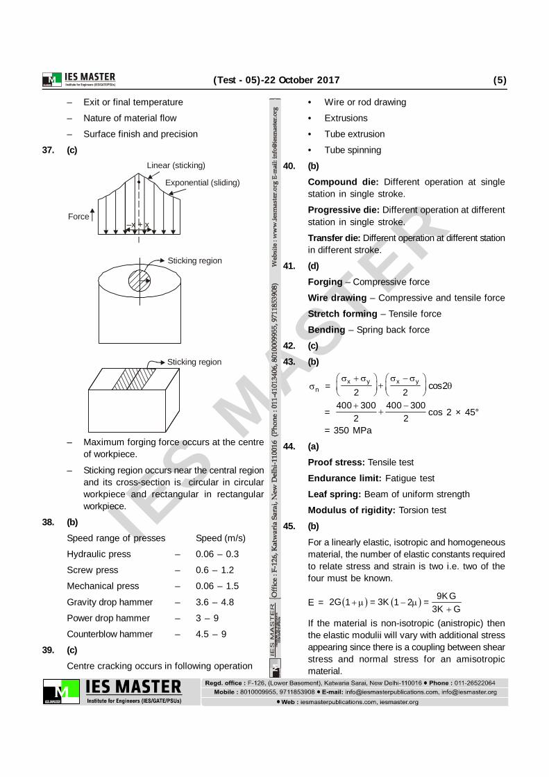
67. (c)P
L/3 2L/3
2P/3 P/3Maximum bending moment would be under theconcentrated load.
Mmax =P 2L3 3
Mmax =2PL
9
Maximum longitudinal/bending stress
= maxMZ
max = 2 22PL 6 4 PL
9 3bd bd
Maximum shear force would be under the supportnear to the concentrated load.
SFmax =2P3
Maximum shear stress
= 1.5 (average shear stress)
max = maxSF1.5
bd
max =3 2 P2 3 bd
max =Pbd
now, given that,
max = max
24 PL3 bd
=Pbd
L 3d 4
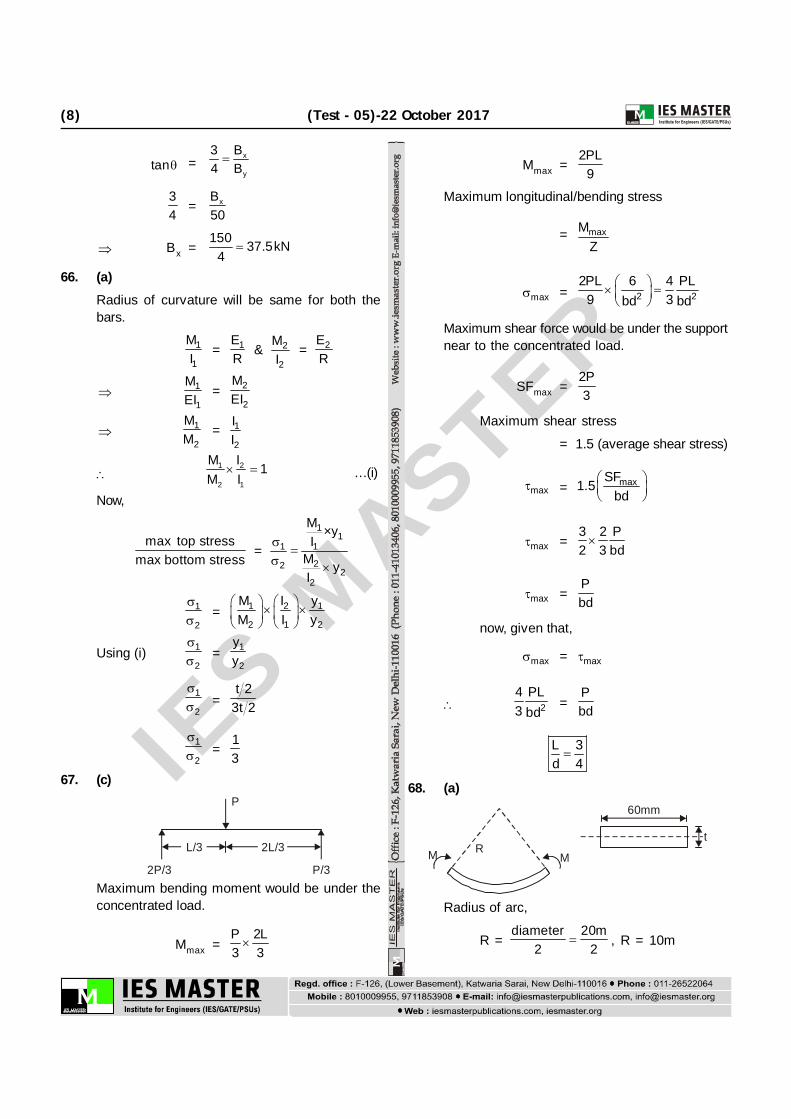
68. (a)60mm
tR
MM
Radius of arc,
R = diameter 20m
2 2 , R = 10m

IES M
ASTER
(Test - 05)-22 October 2017 (9)
Using, flexural formula
MI
=
Ey R
max is given 100 MPa, then
max
maxy
=ER
100t 2
=5
32 10
10 10
t = 10mm
andMI
= y
M =3100 60 10
10 2 12
M = 100 N-mA B C
50 kN 100 kN
300mm200mm69. (d)
When 100 kN acting alone:
UI =
22 3
5P 100 10 5002AE 2 250 2 10
l = 50000 Nmm
When 100 kN and 50 kN acting simultaneously:
50 kN 100 kN
300mm200mmUII = Ui + Uii
=
23
5150 10 2002 250 2 10
23
5100 10 3002 250 2 10
= 75000 Nm
Ratio = I
II
U 50000 0.67U 75000
70. (a)2P 2P
2PL
VCVA
l l2PL
A B C
Taking moment about (c)
AV 2 2P 2PL 2PL 0 l l
A2V 6PLl
AV 3P
cV P
71. (c)
n = x y x y cos22 2
= 4 6 4 6 cos60º
2 2
= – 1 + 2.5
= + 1.5 kN/m2
72. (d)Max shear stress induced
fs = 6
23 3
16T 16 4 10 94.31N mmd 60
Shear stress at a distance of 10mm from theaxis of the shaft
q = sr fR
q =10 94.3130
= 31.44 N/mm2
Ratio =94.31 2.99 331.44
73. (a)
As we know
T GJGst. Jst = GAl ·JAl
477 5032
= 4 4227 d 50
32

IES M
ASTER
(10) (Test - 05)-22 October 2017
d2 = 70.04 mm
74. (a)
d =TdxGJ
dx
x
0 T xo
d = oT x dxGJ
=L
o0
1 T x dxGJ
=2
oT L1GJ 2
= 2
oT L2GJ
75. (d)
T = I
1800 = 3000
= 21800 0.6 rad/s3000
Angular velocity after 10 s
= t= 0.6 × 10 = 6 rad/s
Kinetic energy = 21 I2
= 21 3000 62
= 3000 × 18
= 54 kJ
76. (b)Let the distance travelled by the ball before itstarts falling be x
Then, 0 = 302 – 2gx
x = 2 230 30 900 50m= = =2 g 2 9 2 9
Total height = 50 100m=x
Let velocity with which it strikes the ground = v
Then, v2 = 2g × 100 = 2 × 900
v = 2 30 42= m/s
77. (b)
mg sin
500 N
mg cos
30°
For equilibrium along the plane,
mgsin = mgcos 500
mg(sin cos ) = 500
mg =500
sin cos
=500 2500N=
1 3 32 5 2
78. (a)Considering the forces at point A, only verticalforce is 8t and there is no horizontal force at A.Hence, force in member AC = zero.
B
A C
8t
79. (b)Tilt factor for beam radiation is the ratio of beamradiation on surface under consideration and thebeam radiation on a horizontal surface.
80. (a)81. (c)

IES M
ASTER
(Test - 05)-22 October 2017 (11)
1360 W/m2
Solar insolation (Ion)
= sc
360nI 1 0.33cos365
= 1353 360n1 0.33cos365
For March 22,
Jan – 31
Feb – 28
Mar – 22
n = 81 days
Ion =
This is greater than 1
360 811353 1 0.033 cos365
So, Ion is greater than 1353
only option (c) must be correct.
82. (b)2 and 4
83. (c)
Fill factor = max
SC OC
PI V =
12 10025 0.6
= 80%
84. (d)
Wind has low carbon emissions and theresources is quite widespread and can helpwith energy security in those regions withgood wind.
While competitive with fossil fuels, generationin the best sites, it is generally moreexpensive.
The International Energy Agency (IEA) havepredicted that wind could provide even upto25–30% of global electricity demand by 2050which is greater than 12%.
85. (c)Solar panels are likely to be most economic awayfrom the electricity grid and for small powerapplications.
86. (c)Zero
When the external resistance is completelyshortened, the short-circuit current Isc is obtained.The terminal voltage for the short-circuit conditionis zero, so power produced is also zero.
87. (c)Approximately no dependence on D as spacingand swept area of turbine both proportional to D2.
88. (a)Wind available energy
P = 3s
1 A V2
sP
A = 3V
2
= 5
31.015 10 1.18 kg/m287 300
sP
A = 31 1.18 (12)2 = 1019.52 Watt/m2
Maximum power = 0.593 × Power available
= 0.593 × 1019.52
= 604.57 Watt/m2
89. (b)
90. (a)91. (c)
Wet cattle dung is the main source of biogas.92. (c)
Water supply for biomass can be a significantconcern and biocrops can be in competition withfood crops.
Biomass can be stored but it is not a carbon-neutral fuel as there are always some associatedemission associated with the clearance, cultivationand harvesting of the biomass.
93. (d)For maximum power extraction
a = 13
Cf = 1 1 84a 1 a 4 1 93 3
94. (d)95. (c)
IES M
ASTER
(12) (Test - 05)-22 October 2017
96. (d)97. (b)98. (d)99. (c)100. (b)
In computer operating system, a loader is acomponent that locates a given program in offlinestorage (such as hard disk), load it to mainstorage.
101. (d)102. (c)
Hall voltage, VH = HR BIb
RH = 7.4 × 10⁻¹¹ ; B = 2 Wb/m2 ; I = 120 A,b = 0.2 mm
VH =
11
3
7.4 10 2 1200.2 10
VH = 88.8 V 89 V
103. (a)1 only
104. (c)105. (b)
Parallel robot : A parallel manipulator is amechanical system that uses several computercontrolled chains to support a single platform.Several links are connected to platform so formsmany loops.
106. (d)The process of establishment of a relationshipbetween the input to the instrument and outputfrom the instrument is called as static callibration.It is also simply called as callibration.
107. (d)All the (1), (2), (3), (4), (5) and (6)
108. (c)Stroboscope is not a position sensor, it is aninstrument used to make cyclically moving objectappear to be slow moving, or stationary.
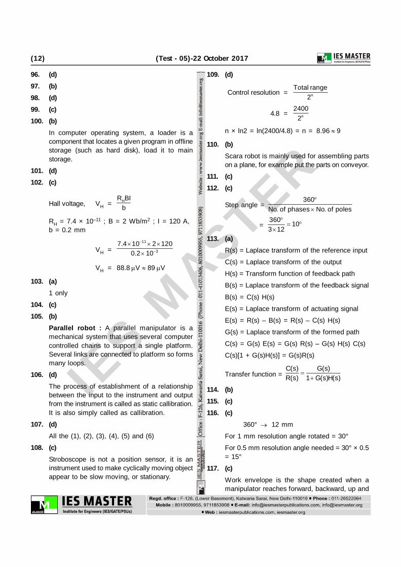
109. (d)
Control resolution = n
Total range2
4.8 = n
24002
n × ln2 = ln(2400/4.8) = n = 8.96 9
110. (b)Scara robot is mainly used for assembling partson a plane, for example put the parts on conveyor.
111. (c)112. (c)
Step angle = 360
No. of phases No. of poles
=
360 103 12
113. (a)R(s) = Laplace transform of the reference input
C(s) = Laplace transform of the output
H(s) = Transform function of feedback path
B(s) = Laplace transform of the feedback signal
B(s) = C(s) H(s)
E(s) = Laplace transform of actuating signal
E(s) = R(s) – B(s) = R(s) – C(s) H(s)
G(s) = Laplace transform of the formed path
C(s) = G(s) E(s) = G(s) R(s) – G(s) H(s) C(s)
C(s)[1 + G(s)H(s)] = G(s)R(s)
Transfer function = C(s) G(s)R(s) 1 G(s)H(s)
114. (b)115. (c)116. (c)
360° 12 mm
For 1 mm resolution angle rotated = 30°
For 0.5 mm resolution angle needed = 30° × 0.5= 15°
117. (c)Work envelope is the shape created when amanipulator reaches forward, backward, up and
IES M
ASTER
(Test - 05)-22 October 2017 (13)
down. A robot can only perform within the confinesof this work envelope.
118. (c)119. (b)
Span of thermometer = 250 – 100 = 150°C
Maximum static error =
0.2 100 0.135
150120. (b)
Speed of flywheel = 2800 700 rpm
4121. (a)
122. (a)A servomechanism, is an automatic device thatuses error sensing negative feedback to correctthe performance of a mechanism and is definedby its function and the servo robot is a closedloop system as it allows for a feedback.
123. (a)Valves is defined as any device by which the flowof liquid can be controlled by obstructing the flowof liquid and is all but impossible to design apractical fluid power system without some meansof controlling the volume and pressure of the fluid.
124. (c)Closed loop system has feedback to accountenvironmental changes and becomes stable.
125. (b)126. (b)
Vacuum is provided to avoid the dispersion ofelectron after magnetic lens in EBM. This vacuumis giving an addition function of providing efficientshield to the weld bead.
127. (c)Cold working increases the dislocation density.
128. (b)
129. (a)130. (d)
• For simple tubular products stationary ormoving mandrel may be utilized in extrusion.
• For products with complex cavities or multiple
cavities can be manufactured with the help ofspider, mandrel die or porthole die, bridge dieor topedo die.
131. (a)Clearance in cup drawing operation is generallylarger than clearance in punching or blankingoperation. Because it helps in bending theworkpiece on die radius otherwise chances oftearing or piercing will increase.
132. (b)133. (a)
Acetone is used to store acetylene in acetylenecylinder and it is in liquid state. If it is kept inhorizontal position then acetone can enter theblow pipe and may result in explosion.
134. (b)• Oxidizing f lame produces maximum
temperature because acetylene completelyburns.
• Oxidizing flame is used for welding Cu, Cu-Zn alloys, as it produces oxide layer on weldpool which prevents the escape of low meltingpoint material.
135. (a)
Short sprues are desirable because theyminimize the kinetic energy that the moltenmetal acquires during its fall.
Tapered sprues prevent vortex formation andavoids air aspiration effect.
136. (a)137. (b)
Flat ends have low resistance to pressure as itis an unsupported diaphragm while ahemispherical end shape causes all the forces toact as tension which thin metal sheets can resisteasily.
Axial stress in hemispherical ends is 1/2 of hoopstress and hence longitudinal joints are strongerthan transverse joints.
138. (d)For the given loading bending moment is notconstant throughout the length.

IES M
ASTER
(14) (Test - 05)-22 October 2017
139. (d)140. (a)141. (c)
Mohr’s circle represents the transformation ofsecond-order tensor.
142. (a)143. (c)
As long as load is in core circle of dia d4
, also
known as kern, the stresses will be compressivethroughout.
Statement (i) is correct.
Statement (ii) is wrong.
144. (c)
Assertion is correct.
The load required to produce a unit deflectionin a spring is called stiffness of spring.
4
3W GdStiffness, K
64R n
145. (d)The inclination of line joining the Mohr’s circleand origin O with X-axis equals the angle between
resultant stress and the normal of the plane forwhich P stand for , .
P
R
146. (c)Area under load deformation curve within elasticlimit is called resilence.
147. (a)148. (b)149. (a)
Horizontal axis wind machine has to be parallelto direction of wind stream.
150. (c)The pyroheliometer is a broadband instrument thatmeasures the direct (or beam) component of solarradiation at normal incidence. It does not measurediffuse radiation.
The diffuse radiation is measured by pyrometer.