Embed Size (px)
Citation preview
B. Buth, G. Rabe, T. Seyfarth (Eds.): SAFECOMP 2009, LNCS 5775, pp. 326–341, 2009. © Springer-Verlag Berlin Heidelberg 2009
Establishing a Framework for Dynamic Risk Management in ‘Intelligent’ Aero-Engine Control
Zeshan Kurd1, Tim Kelly1, John McDermid1, Radu Calinescu2, and Marta Kwiatkowska2
1 High Integrity Systems Engineering Group Department of Computer Science
University of York, York, YO10 5DD, UK {zeshan.kurd,tim.kelly,john.mcdermid}@cs.york.ac.uk
2 Computing Laboratory, University of Oxford, Wolfson Building, Parks Road, Oxford, OX1 3QD, UK
{radu.calinescu,marta.kwiatkowska}@comlab.ox.ac.uk
Abstract. The behaviour of control functions in safety critical software systems is typically bounded to prevent the occurrence of known system level hazards. These bounds are typically derived through safety analyses and can be imple-mented through the use of necessary design features. However, the unpredict-ability of real world problems can result in changes in the operating context that may invalidate the behavioural bounds themselves, for example, unexpected hazardous operating contexts as a result of failures or degradation. For highly complex problems it may be infeasible to determine the precise desired behav-ioural bounds of a function that addresses or minimises risk for hazardous op-eration cases prior to deployment. This paper presents an overview of the safety challenges associated with such a problem and how such problems might be addressed. A self-management framework is proposed that performs on-line risk management. The features of the framework are shown in context of em-ploying intelligent adaptive controllers operating within complex and highly dynamic problem domains such as Gas-Turbine Aero Engine control. Safety as-surance arguments enabled by the framework necessary for certification are also outlined.
1 Introduction
The use of Artificial Intelligence (AI) in highly critical roles has long been a subject of scepticism and controversy within the safety community. Although such technol-ogy is being increasingly acclaimed for its qualities and performance capabilities their inherent unpredictability has gained limited recognition within current safety devel-opment standards and guidelines [1]. At the macro level, AI paradigms such as Multi-Agent Systems may be employed in the complex simulation management and control of Systems of Systems [2]. At the micro-level, intelligent machine learning paradigms can be employed for control systems such as Artificial Neural Networks (ANNs) and Fuzzy Logic Systems (FLSs).
Establishing a Framework for Dynamic Risk Management in ‘Intelligent’ 327
There are many motivations for using AI paradigms - some of which include ad-dressing incomplete specifications, uncertainty, unexpected conditions, complexity and changing environments. Many of these AI paradigms fall into the category of self-* or autonomous systems. These are Self-Managed systems that are capable of self-configuration, self-adaptation, self-healing, self-monitoring and self-tuning [3].
The emergence of self-governing or autonomous solutions to address complex, highly dynamical and unpredictable real world problems has led to major challenges in achieving compelling and acceptable safety assurance necessary for certification. Previous work on the safety of Intelligent Adaptive Systems [4-6] has addressed these issues by employing design features and a set of behavioural (functional) safety bounds within which such paradigms are able to learn and adapt their behaviour once deployed. This can be achieved using self-* algorithms such as self-tuning and self-generation [5]. Although this may be sufficient for problems where the functional safety requirements are well defined in some other problems it may be necessary to change the defined safety bounds themselves post certification in the event of unex-pected failures or system degradation.
In section 2, the problem of managing unexpected operating conditions is high-lighted in context of the Gas Turbine Aero-Engine. Section 3 of the paper presents an argument about how such operating conditions can be addressed through adaptive systems. Section 4 presents a framework detailing key activities, how they contribute to safety assurance and major safety challenges in context of Gas Turbine Aero-Engine control.
2 Problem Definition: Managing Changing Requirements
Gas Turbine Engines (GTE) are a real world example of a complex and a highly dy-namical system that is comprised of many interconnected components. GTEs are
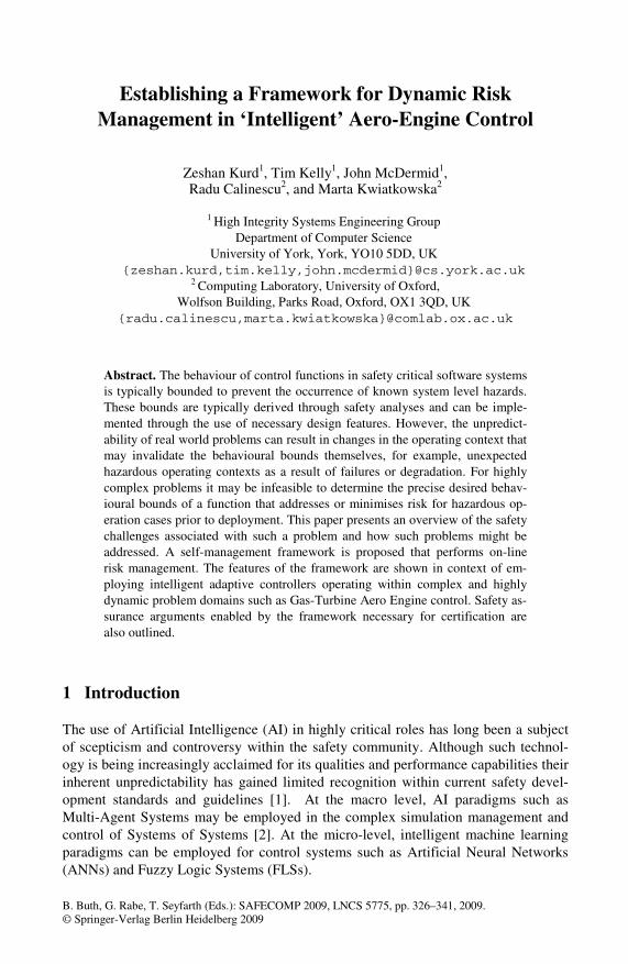
Fig. 1. Typical Mechanical Layout of a Twin-Spool Gas Turbine Aero-Engine
328 Z. Kurd et al.
internal combustion heat engines which convert heat energy into mechanical energy. There are three main elements within the GTE namely; compressor, combustion chamber and a turbine placed on a common shaft. The GTE illustrated in Figure 1 shows the typical mechanism for producing thrust and highlights the engine acro-nyms. The initial stage involves atmospheric air entering the engine body. Air that is drawn in then enters the compressor which is divided into the LP and HP (Low and High Pressure) compressor units (twin-spool). Air pressure is first raised by the LP Compressor unit and then further increased by the HP Compressor unit. The Inlet Guide Vane (IGV) is used to match the air from the fan to the HP compressor charac-teristics. Pressurised air then reaches the combustion chamber where engine fuel is mixed with the compressed air and ignited at constant pressure. This results in a rise in temperature and expansion of the gases. A percentage of the airflow is then mixed with the combusted gas from the turbine exit. This is then ejected through the jet pipe and variable nozzle area to produce a propulsive thrust.
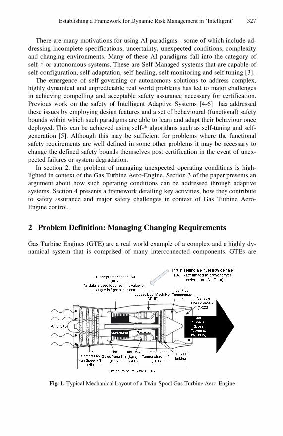
At the system-level, a major engine hazard is engine ‘surge’ which can lead to loss of thrust (XGN – ref. Figure 1) or engine destruction. Engine surge is caused by ex-cessive aerodynamic pulsations transmitted across the engine and is of particular concern during high thrust demand. For typical GTEs, there is a ‘surge line’ which is used as a measure of aerodynamic stability. As shown in Figure 2 the ‘surge line’ defines various surge points across the engine speed range. To provide safety assur-ance that the risk of engine surge is controlled a ‘working line’ is defined that speci-fies an extreme of allowable engine behaviour at the system level.
At the local level of the engine there are various controllers designed to fulfil en-gine design objectives and performance efficiency. An example of such objectives is shown in the “expected operating conditions” column in Table 1.
Fig. 2. Typical engine surge margins and working lines
Table 1. Operating Context Dependant Engine Safety Objectives
Objectives for Expected Operating Conditions Objectives for Collision Avoidance
,...
Establishing a Framework for Dynamic Risk Management in ‘Intelligent’ 329
LPSM and HPSM are Low and High Pressure Surge Margins that indicate how close the engine is to instability and the surge condition. To avoid control system design flaws in such complex systems, rigorous analytical techniques are needed to cope with various types of changes. Such changes include changing goals, user requirements and opera-tional and system conditions. Engine control is typically designed to accommodate for predicted changes such as expected engine degradation and wear between service inter-vals. Suitable AI controllers can be employed to address operating context changes given specified safety objectives. For example, previous work [7] has demonstrated the use of fuzzy logic systems for control of Inlet Guide Vanes, fuel flow (WFE), and en-gine nozzle (NOZZ) using Mamdani and Takagi-Sugeno [8] fuzzy rules. Such work has been shown to offer improved performance (such as thrust maximisation) over linear or non-linear polynomial schedulers [7].
In real world scenarios the engine may be expected to perform in the event of ‘un-expected’ changes such as unexpected and abrupt excessive turbine blade wear or excessive turbine blade over-heating (i.e. prolonged resulting in high risk of imminent blade failure). Such emergency scenarios may arise when the engine is on-line, in operation and where immediate maintenance is unavailable. For such cases, the assumed safety objectives may no longer be valid. For example, column “objectives of collision avoidance” in Table 1 defines appropriate safety objectives that enable maximum thrust to avoid imminent collision. These safety objectives are far more flexible than that defined for ‘normal’ expected operating contexts but are not suitable for ‘normal’ operating conditions. The implication of such changes in the objectives is that the intelligent controllers can adapt themselves to offer a suitable solution from a context-specific solution space. Forcing intelligent controllers to adapt according to a single fixed set of objectives could result in the inability of the adaptive system to find an appropriate solution to address the current operating conditions given engine capabilities and constraints. Such ‘intelligent’ solutions could contribute to exacerbating the risk of an accident when they are forcibly (an unavoidably) used out of context. Addressing unexpected engine changes through the use of intelligent self-* systems can greatly increase the probability of achieving system or mission goals when operating in stochastic environments.
As an example, our previous work employed the Safety Critical Artificial Neural Network [5] (SCANN) within the GTE. SCANN is a ‘hybrid’ nonlinear function approximator that exploits both fuzzy and neural network paradigms for mutual bene-fit and overcomes many problems traditionally associated with ANNs [9]. Through manual hazard analysis (prior to deployment) functional safety barriers (that only allow actions to be executed once defined preconditions are satisfied [10]) for the SCANN function are derived and guarante behaviour to lie within derived behav-ioural bounds and prevent the occurrence of identified failure modes [4]. However, during on-line learning and adaptation the behavioural bounds are always fixed thereby leading to possible adaptations within a single pre-defined operating context. This means that under unexpected conditions the behavioural bounds may instantly become invalid and safety assurance can no longer be provided that the risk of hazard occurrence or accident can be minimised. Furthermore, it is shown that such low-level behavioural bounds are impractical for safety engineers to determine for multiple-input controllers [4]. Further difficulties arise since each adaptive controller cannot be considered independently of other adaptive controllers. To address the problem of
330 Z. Kurd et al.
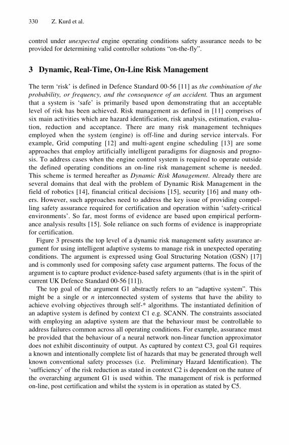
control under unexpected engine operating conditions safety assurance needs to be provided for determining valid controller solutions “on-the-fly”.
3 Dynamic, Real-Time, On-Line Risk Management
The term ‘risk’ is defined in Defence Standard 00-56 [11] as the combination of the probability, or frequency, and the consequence of an accident. Thus an argument that a system is ‘safe’ is primarily based upon demonstrating that an acceptable level of risk has been achieved. Risk management as defined in [11] comprises of six main activities which are hazard identification, risk analysis, estimation, evalua-tion, reduction and acceptance. There are many risk management techniques employed when the system (engine) is off-line and during service intervals. For example, Grid computing [12] and multi-agent engine scheduling [13] are some approaches that employ artificially intelligent paradigms for diagnosis and progno-sis. To address cases when the engine control system is required to operate outside the defined operating conditions an on-line risk management scheme is needed. This scheme is termed hereafter as Dynamic Risk Management. Already there are several domains that deal with the problem of Dynamic Risk Management in the field of robotics [14], financial critical decisions [15], security [16] and many oth-ers. However, such approaches need to address the key issue of providing compel-ling safety assurance required for certification and operation within ‘safety-critical environments’. So far, most forms of evidence are based upon empirical perform-ance analysis results [15]. Sole reliance on such forms of evidence is inappropriate for certification.
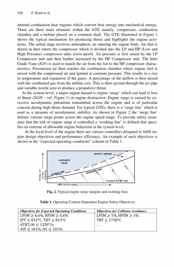
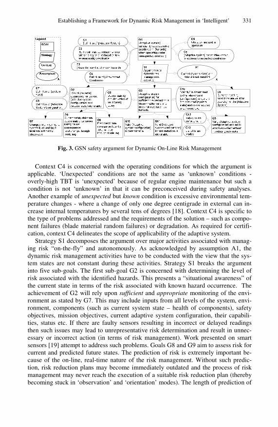
Figure 3 presents the top level of a dynamic risk management safety assurance ar-gument for using intelligent adaptive systems to manage risk in unexpected operating conditions. The argument is expressed using Goal Structuring Notation (GSN) [17] and is commonly used for composing safety case argument patterns. The focus of the argument is to capture product evidence-based safety arguments (that is in the spirit of current UK Defence Standard 00-56 [11]).
The top goal of the argument G1 abstractly refers to an “adaptive system”. This might be a single or n interconnected system of systems that have the ability to achieve evolving objectives through self-* algorithms. The instantiated definition of an adaptive system is defined by context C1 e.g. SCANN. The constraints associated with employing an adaptive system are that the behaviour must be controllable to address failures common across all operating conditions. For example, assurance must be provided that the behaviour of a neural network non-linear function approximator does not exhibit discontinuity of output. As captured by context C3, goal G1 requires a known and intentionally complete list of hazards that may be generated through well known conventional safety processes (i.e. Preliminary Hazard Identification). The ‘sufficiency’ of the risk reduction as stated in context C2 is dependent on the nature of the overarching argument G1 is used within. The management of risk is performed on-line, post certification and whilst the system is in operation as stated by C5.
Establishing a Framework for Dynamic Risk Management in ‘Intelligent’ 331
Fig. 3. GSN safety argument for Dynamic On-Line Risk Management
Context C4 is concerned with the operating conditions for which the argument is applicable. ‘Unexpected’ conditions are not the same as ‘unknown’ conditions - overly-high TBT is ‘unexpected’ because of regular engine maintenance but such a condition is not ‘unknown’ in that it can be preconceived during safety analyses. Another example of unexpected but known condition is excessive environmental tem-perature changes - where a change of only one degree centigrade in external can in-crease internal temperatures by several tens of degrees [18]. Context C4 is specific to the type of problems addressed and the requirements of the solution – such as compo-nent failures (blade material random failures) or degradation. As required for certifi-cation, context C4 delineates the scope of applicability of the adaptive system.
Strategy S1 decomposes the argument over major activities associated with manag-ing risk “on-the-fly” and autonomously. As acknowledged by assumption A1, the dynamic risk management activities have to be conducted with the view that the sys-tem states are not constant during these activities. Strategy S1 breaks the argument into five sub-goals. The first sub-goal G2 is concerned with determining the level of risk associated with the identified hazards. This presents a “situational awareness” of the current state in terms of the risk associated with known hazard occurrence. The achievement of G2 will rely upon sufficient and appropriate monitoring of the envi-ronment as stated by G7. This may include inputs from all levels of the system, envi-ronment, components (such as current system state – health of components), safety objectives, mission objectives, current adaptive system configuration, their capabili-ties, status etc. If there are faulty sensors resulting in incorrect or delayed readings then such issues may lead to unrepresentative risk determination and result in unnec-essary or incorrect action (in terms of risk management). Work presented on smart sensors [19] attempt to address such problems. Goals G8 and G9 aim to assess risk for current and predicted future states. The prediction of risk is extremely important be-cause of the on-line, real-time nature of the risk management. Without such predic-tion, risk reduction plans may become immediately outdated and the process of risk management may never reach the execution of a suitable risk reduction plan (thereby becoming stuck in ‘observation’ and ‘orientation’ modes). The length of prediction of
332 Z. Kurd et al.
future risks in the temporal sense can be used later to ‘life’ proposed solutions and provide valid stopping conditions. For example, when attempting to address the issue of excessive NH shaft speed, in the time taken to find a solution the system enters a condition where TBT is over the prescribed limits. As a result, non-functional tempo-ral issues will play an important role and must be addressed through prediction and ‘validity’ of plans based on non-functional temporal properties. Prediction will rely upon the provision of a suitable model that captures the cause-consequence relation-ship of relevant variables. Failures with the modelling and it’s output would result in ‘invalid’ risk reduction plans and could introduce new risks. The argument of high fidelity modelling and how associated failure modes are addressed will therefore involve decomposition of goal G9.
The next step for risk management is assuring that an adaptive system ‘configura-tion’ or ‘solution’ can indeed by determined and that such a solution does not result in introducing new and unnecessary safety risks (G3). For example, safety risks can be prioritised based on the system level effects – maximising thrust to avoid an accident is acceptable given that risks associated with over-TBT and shaft overspeed are of lower priority. Risks are therefore managed depending on the highest level of risk and the solution (which may be non-dominant). This gives rise to the notion of determinability of managing such risks through an adaptive system configuration as stated in G10. Ap-proaches to identify valid solutions can be used to further decompose goal G11.
The behaviour of the adaptive components must comply with the derived adaptive system configuration solution (G5). One safety concern is that the enforcement itself may introduce new risks and failures especially since it is performed in real-time and whilst the system is in operation. For example, defining new functional safety barriers for the SCANN may result in problems with the current operating control point – this may result in a control output spike (or high derivative changes) resulting in local-level failure modes.
Finally, G6 provides assurance that the applicability of the adaptive system for the context in which it has been defined is valid.
Due to space constraints a fully decomposed safety argument is not shown here. The following section shows how activities within a self-management framework can contribute to generating suitable forms of safety argument and assurance for Figure 3.
4 A ‘Safe’ Self-management Framework
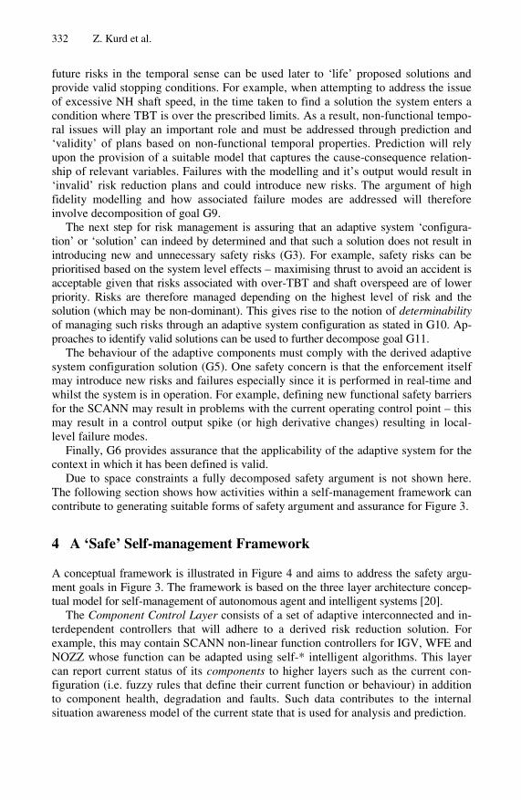
A conceptual framework is illustrated in Figure 4 and aims to address the safety argu-ment goals in Figure 3. The framework is based on the three layer architecture concep-tual model for self-management of autonomous agent and intelligent systems [20].
The Component Control Layer consists of a set of adaptive interconnected and in-terdependent controllers that will adhere to a derived risk reduction solution. For example, this may contain SCANN non-linear function controllers for IGV, WFE and NOZZ whose function can be adapted using self-* intelligent algorithms. This layer can report current status of its components to higher layers such as the current con-figuration (i.e. fuzzy rules that define their current function or behaviour) in addition to component health, degradation and faults. Such data contributes to the internal situation awareness model of the current state that is used for analysis and prediction.
Establishing a Framework for Dynamic Risk Management in ‘Intelligent’ 333
Fig. 4. Conceptual framework for unexpected operating conditions on-line
The Change Management Layer observes relevant environmental changes, main-tains plans and effects changes to the Component Control Layer. The Change Man-agement Layer responds to new states reported by the Component Layer and responds to new objectives required of the system introduced from the operating conditions and environment. This layer contains the “what” must be done, “why” it should be done and “how” in the form of a Safety Policy [21]. This layer also contains solutions gen-erated from self-* intelligent algorithms and manages changes upon the adaptive controller behaviour in on-line fashion without introducing new risks. Because of the on-line application of the framework and the dynamic nature of the problem this layer also manages the ‘life’ or the ‘validity’ of the plans and solutions generated and re-quests re-planning if the assumptions of the plans and solutions no longer hold for the current operating conditions.
The Goal Management Layer deals with dynamic risk reduction through generat-ing suitable planning and solutions using high-fidelity models for situation awareness and prediction. This layer takes as input the current states, safety goals, performance goals and constraints. A hierarchical relationship is formed from the opera-tional\mission (macro) level down to local (micro) levels. This layer produces a Safety Policy that expresses what current prioritised safety (risk related) objectives need to be achieved, why they need to be achieved and by whom (adaptive controllers that will fulfil the Policy). In addition, the layer also generates solutions based on the input of the Safety Policy. Multi-Objective intelligent algorithms are employed with a high-fidelity model of the system and prediction techniques. ‘Prediction’ of risk and future states has a major role in defining the ‘validity’ of the plans and solutions.
The entire framework operates on-line and continuously thereby becoming the main approach for adaption of the controllers. The framework operation has also been defined in the spirit of the Observe-Orient-Decide-Act (OODA) loop commonly employed for highly dynamic environments for safety-based risk management. To understand how the framework contributes to the safety assurance argument the fol-lowing section proposes possible solutions in context of the GTE.
334 Z. Kurd et al.
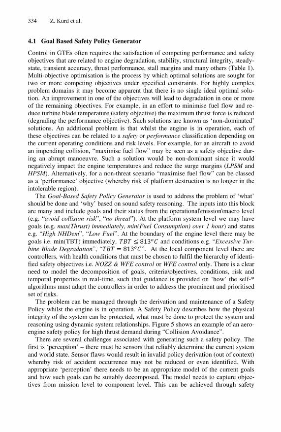
4.1 Goal Based Safety Policy Generator
Control in GTEs often requires the satisfaction of competing performance and safety objectives that are related to engine degradation, stability, structural integrity, steady-state, transient accuracy, thrust performance, stall margins and many others (Table 1). Multi-objective optimisation is the process by which optimal solutions are sought for two or more competing objectives under specified constraints. For highly complex problem domains it may become apparent that there is no single ideal optimal solu-tion. An improvement in one of the objectives will lead to degradation in one or more of the remaining objectives. For example, in an effort to minimise fuel flow and re-duce turbine blade temperature (safety objective) the maximum thrust force is reduced (degrading the performance objective). Such solutions are known as ‘non-dominated’ solutions. An additional problem is that whilst the engine is in operation, each of these objectives can be related to a safety or performance classification depending on the current operating conditions and risk levels. For example, for an aircraft to avoid an impending collision, “maximise fuel flow” may be seen as a safety objective dur-ing an abrupt manoeuvre. Such a solution would be non-dominant since it would negatively impact the engine temperatures and reduce the surge margins (LPSM and HPSM). Alternatively, for a non-threat scenario “maximise fuel flow” can be classed as a ‘performance’ objective (whereby risk of platform destruction is no longer in the intolerable region).
The Goal-Based Safety Policy Generator is used to address the problem of ‘what’ should be done and ‘why’ based on sound safety reasoning. The inputs into this block are many and include goals and their status from the operational\mission\macro level (e.g. “avoid collision risk”, “no threat”). At the platform system level we may have goals (e.g. max(Thrust) immediately, min(Fuel Consumption) over 1 hour) and status e.g. “High NHDem”, “Low Fuel”. At the boundary of the engine level there may be goals i.e. min(TBT) immediately, and conditions e.g. “Excessive Tur-bine Blade Degradation”, “ ”. At the local component level there are controllers, with health conditions that must be chosen to fulfil the hierarchy of identi-fied safety objectives i.e. NOZZ & WFE control or WFE control only. There is a clear need to model the decomposition of goals, criteria\objectives, conditions, risk and temporal properties in real-time, such that guidance is provided on ‘how’ the self-* algorithms must adapt the controllers in order to address the prominent and prioritised set of risks.
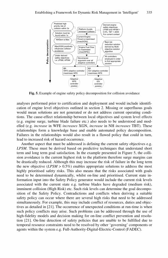
The problem can be managed through the derivation and maintenance of a Safety Policy whilst the engine is in operation. A Safety Policy describes how the physical integrity of the system can be protected, what must be done to protect the system and reasoning using dynamic system relationships. Figure 5 shows an example of an aero-engine safety policy for high thrust demand during “Collision Avoidance”.
There are several challenges associated with generating such a safety policy. The first is ‘perception’ – there must be sensors that reliably determine the current system and world state. Sensor flaws would result in invalid policy derivation (out of context) whereby risk of accident occurrence may not be reduced or even identified. With appropriate ‘perception’ there needs to be an appropriate model of the current goals and how such goals can be suitably decomposed. The model needs to capture objec-tives from mission level to component level. This can be achieved through safety
Establishing a Framework for Dynamic Risk Management in ‘Intelligent’ 335
Platform Avoids imminent Collision
Current Engine Thrust is maximised (max(XGN))
Predicted high priority risk of collision within 3s
NHDem is Max
Engine Fuel Flow is maximised (max(WFE))
Derived engine safety objectives LPSM and HPSM > 0.5%, TBT < 2000For current context
Decompose argument over all adaptive controllers
G1WFE adaptive controller maximises WFE
G1IGV adaptive controller maximises WFE
Adaptive WFE
controller solution
Under derived safety objectives i.e. LPSM, HPSM
Best risk reduction solution derived by Multi-objective solution algorithm
Adaptive IGV
controller solution
All controllers employed in order to find appropriate solution
Solution must be found within 1s
Max(XGN) positively influences collision avoidance
Fig. 5. Example of engine safety policy decomposition for collision avoidance
analyses performed prior to certification and deployment and would include identifi-cation of engine level objectives outlined in section 2. Missing or superfluous goals would mean solutions are not generated or do not address current operating condi-tions. The cause-effect relationship between local objectives and system level effects (e.g. engine surge, turbine blade failure etc.) also needs to be understood and mod-elled (e.g. increase in WFE increases XGN, increase in NH increases TBT). These relationships form a knowledge base and enable automated policy decomposition. Failures in the relationships would also result in a flawed policy that could in turn, lead to increased risk of hazard occurrence.
Another aspect that must be addressed is defining the current safety objectives e.g. LPSM. These must be derived based on predictive techniques that understand short term and long term goal satisfaction. In the example presented in Figure 5, the colli-sion avoidance is the current highest risk to the platform therefore surge margins can be drastically reduced. Although this may increase the risk of failure in the long term the new objective (LPSM > 0.5%) enables appropriate solutions to address the most highly prioritised safety risks. This also means that the risks associated with goals need to be determined dynamically, whilst on-line and prioritised. Current state in-formation input into the Safety Policy generator would include the current risk levels associated with the current state e.g. turbine blades have degraded (medium risk), imminent collision (High Risk) etc. Such risk levels can determine the goal decompo-sition of the Safety Policy. Contradictions and conflicts when deriving a suitable safety policy can occur where there are several high risks that need to be addressed simultaneously. For example, this may include conflict of resources, duties and objec-tives as detailed in [21]. The occurrence of unexpected conditions at run-time is when such policy conflicts may arise. Such problems can be addressed through the use of high-fidelity models and decision making for on-line conflict prevention and resolu-tion [21]. On-line detection of safety policies that are unable to be fulfilled due to temporal resource constraints need to be resolved by other ‘governing’ components or agents within the system e.g. Full-Authority-Digital-Electric-Control (FADEC).
336 Z. Kurd et al.
Non-functional temporal issues and prediction play an important role in generating the Safety Policy. Validity of the policy will be dependent on the current operating context. To reduce the probability of a generated safety policy requiring re-planning and drastic change, prediction techniques can be employed through the use of a suit-able high-fidelity model. The prediction would determine expected future states of the system e.g. TBT is near limits, engine is being used heavily therefore the predicted time before blade failure is t. Time t can then be used to provide a ‘life’ of validity of the Safety Policy and where risk management techniques need to accomplish their activities within the allocated predicted temporal resources. To complete the Safety Policy, low level controller solutions need to be generated that define how current safety risks are addressed.
The approach of using ‘intelligent’ solutions to solve multi-objective problems involving risk is not a new problem especially in the domain of finance [15] and secu-rity [16]. For Safety Policy decomposition we have identified the challenge of ad-dressing numerous risk-related objectives well above the level of adaptive controller solutions. Techniques in Operations Research such as Non-linear Programming (NLP) [22] can be used to address such problems through minimising weighted sum of deviations from goals. Other techniques such as lexicographic goal programming described in [22] categorises goals into levels such that a goal of a particular-level may be of greater priority than one assigned at a different level. For safety, this ap-proach is appealing because it enables the distinction between performance and safety related objectives and is particularly effective when there is a clear priority ordering amongst the goals to be achieved. This can be achieved by inputting risk associated with known hazards and relating the current and predicted states to determine prioriti-sation. The safety challenge is to generate Pareto-efficient solutions thereby resulting in the most effective risk reduction plan possible given the capabilities of the system. A sub-optimal plan could result in exacerbating existing risks. ‘Governor’ agents and multi-agent architectures [23] are seen as approaches to address such problems. In any case, safety assurance needs to be provided that the safety policy has been appropri-ately decomposed, and that the safety policy is ‘valid’ for the current and predicted future operating contexts.
4.2 Component (Controller) Solution Generator
The Component Solution Generator adopts a bottom-up approach to determine ‘how’ adaptive controllers will meet the defined safety policy which is provided as input. Existing approaches to address unexpected operating conditions using adaptive con-trollers include the Situational Controller Methodology (SCM) [18] which has been applied to GTE control. SCM uses neural network pattern recognition algorithms and predefined controller solutions to determine the ideal controller for the current operat-ing context. Such a solution is ‘rigid’ in that the actual scenario may not fall into any particular pre-defined situation and there is no opportunity for re-planning using exist-ing scenario-based solutions (interpolation problems). As highlighted in [18] this greatly limits the potential for acceptable risk reduction strategies by focussing on a limited and potentially inadequate solution space. Other work on the use of Evolu-tionary algorithms for devising optimal Engine schedulers include the Multi-Objective Genetic Algorithm (MOGA) [7]. As described in [7] MOGA has been
Establishing a Framework for Dynamic Risk Management in ‘Intelligent’ 337
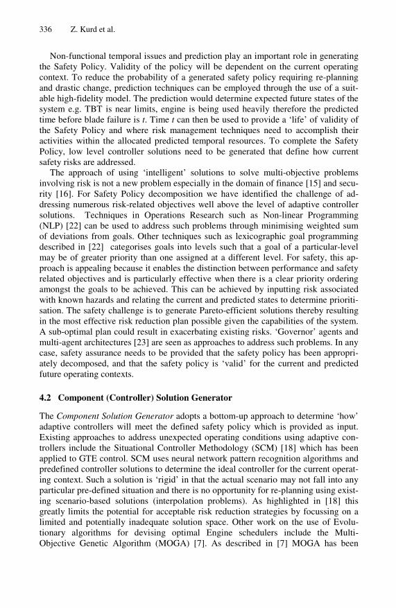
Fig. 6. Approach for ‘safe’ dynamic control of solution space
shown to be a competent algorithm for finding optimal fuzzy schedulers for GTE control. MOGA is composed of three levels and uses genetic algorithms to search for an optimal controller solution of fuzzy control rules. The first two levels generate and analyse the performance (using objectives in Table 1) of potential solutions at differ-ent engine operation points (such as 54, 65, 75, 85, 95% NH). The last level selects the best fuzzy solution (by making trade-offs between objectives). However, such a scheme is limited to off-line aero-engine design and there is little or no safety assur-ance that the behaviour of the scheduler will not lead to system-level hazards (such as discontinuity of function output). An alternative solution introduced here uses a com-bination of the above mentioned approaches (including the SCANN) for mutual bene-fit (in terms of safety assurance) and is illustrated in Figure 6.
As depicted in Figure 6, the Component Solution Generator works on the principle of using high-fidelity cause-effect models of the system to generate valid risk reduc-tion controller solutions. The first step is to input the safety policy which is generated in the previous phase of the framework and specifies safety objectives e.g. LPSM > 0.5%, safety goals e.g. max(XGN) and the proposed actions contracted out to IGV and WFE adaptive controllers. The adaptive controllers (whether they are fuzzy, neu-ral, reactive or deliberative agents) must address failure modes associated with their behaviour that are common to all possible configurations that may be applied (e.g. functional safety barriers). For example, failure modes such as ‘omission’ and ‘com-mission’ of output given an input are applicable to all potential desired controller functions. The safety argument must therefore assure that the adaptive controller addresses such failures through appropriate design features or otherwise as described previously with the SCANN [4]. Such a safety argument can contribute to the decom-position of goal G5 in Figure 3 whereby the adaptive controller will be able to adhere to proposed solutions without causing failures modes that are common to all potential system states.
In Figure 6, the main role of the scenario-scheduler knowledge base is to reduce the time taken for Multi-Objective intelligent algorithms to find a valid solution and contribute to goal G12. The knowledge base would consist of a catalogue of known (foreseeable but unexpected) and unknown (self-generated) operating conditions, respective safety policies and controller based solutions (e.g. Takagi-Sugeno fuzzy rules that define controller behaviour). Part of the catalogue can be preconceived through safety analyses and updated through during post-deployment use when valid solutions are found. Through the philosophy of ‘expect the unexpected’ the time taken to generate a valid solution and re-planning can contribute to achieving
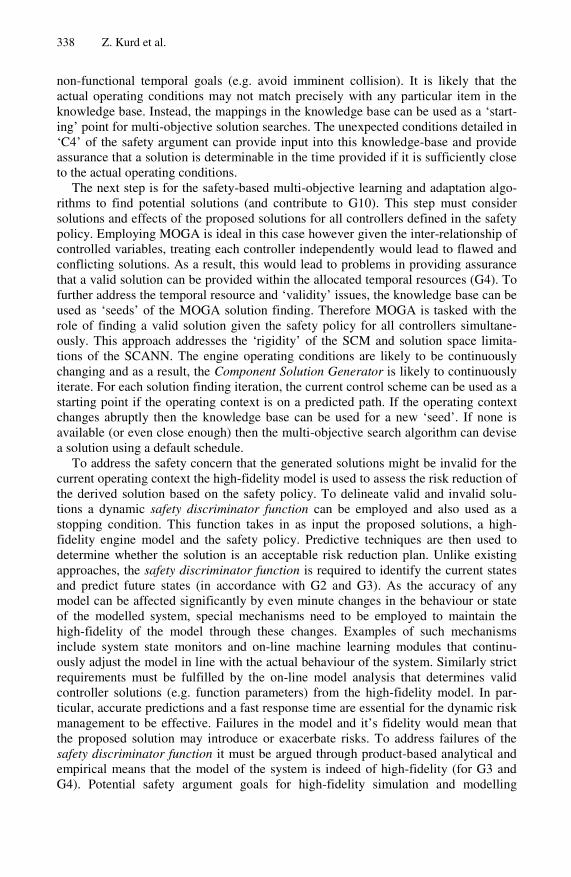
338 Z. Kurd et al.
non-functional temporal goals (e.g. avoid imminent collision). It is likely that the actual operating conditions may not match precisely with any particular item in the knowledge base. Instead, the mappings in the knowledge base can be used as a ‘start-ing’ point for multi-objective solution searches. The unexpected conditions detailed in ‘C4’ of the safety argument can provide input into this knowledge-base and provide assurance that a solution is determinable in the time provided if it is sufficiently close to the actual operating conditions.
The next step is for the safety-based multi-objective learning and adaptation algo-rithms to find potential solutions (and contribute to G10). This step must consider solutions and effects of the proposed solutions for all controllers defined in the safety policy. Employing MOGA is ideal in this case however given the inter-relationship of controlled variables, treating each controller independently would lead to flawed and conflicting solutions. As a result, this would lead to problems in providing assurance that a valid solution can be provided within the allocated temporal resources (G4). To further address the temporal resource and ‘validity’ issues, the knowledge base can be used as ‘seeds’ of the MOGA solution finding. Therefore MOGA is tasked with the role of finding a valid solution given the safety policy for all controllers simultane-ously. This approach addresses the ‘rigidity’ of the SCM and solution space limita-tions of the SCANN. The engine operating conditions are likely to be continuously changing and as a result, the Component Solution Generator is likely to continuously iterate. For each solution finding iteration, the current control scheme can be used as a starting point if the operating context is on a predicted path. If the operating context changes abruptly then the knowledge base can be used for a new ‘seed’. If none is available (or even close enough) then the multi-objective search algorithm can devise a solution using a default schedule.
To address the safety concern that the generated solutions might be invalid for the current operating context the high-fidelity model is used to assess the risk reduction of the derived solution based on the safety policy. To delineate valid and invalid solu-tions a dynamic safety discriminator function can be employed and also used as a stopping condition. This function takes in as input the proposed solutions, a high-fidelity engine model and the safety policy. Predictive techniques are then used to determine whether the solution is an acceptable risk reduction plan. Unlike existing approaches, the safety discriminator function is required to identify the current states and predict future states (in accordance with G2 and G3). As the accuracy of any model can be affected significantly by even minute changes in the behaviour or state of the modelled system, special mechanisms need to be employed to maintain the high-fidelity of the model through these changes. Examples of such mechanisms include system state monitors and on-line machine learning modules that continu-ously adjust the model in line with the actual behaviour of the system. Similarly strict requirements must be fulfilled by the on-line model analysis that determines valid controller solutions (e.g. function parameters) from the high-fidelity model. In par-ticular, accurate predictions and a fast response time are essential for the dynamic risk management to be effective. Failures in the model and it’s fidelity would mean that the proposed solution may introduce or exacerbate risks. To address failures of the safety discriminator function it must be argued through product-based analytical and empirical means that the model of the system is indeed of high-fidelity (for G3 and G4). Potential safety argument goals for high-fidelity simulation and modelling
Establishing a Framework for Dynamic Risk Management in ‘Intelligent’ 339
NHDem
WFE
Controller
IGV
Controller
NOZZ
Controller
DESIRED ACTUATOR
FAULT STATE
ACTUATOR FAULTS
SPEY ENGINE MODEL
DEGRADATION VARIABLES
ENGINE PARAMETERS
+ -
ENVIRONMENTAL VARIABLES
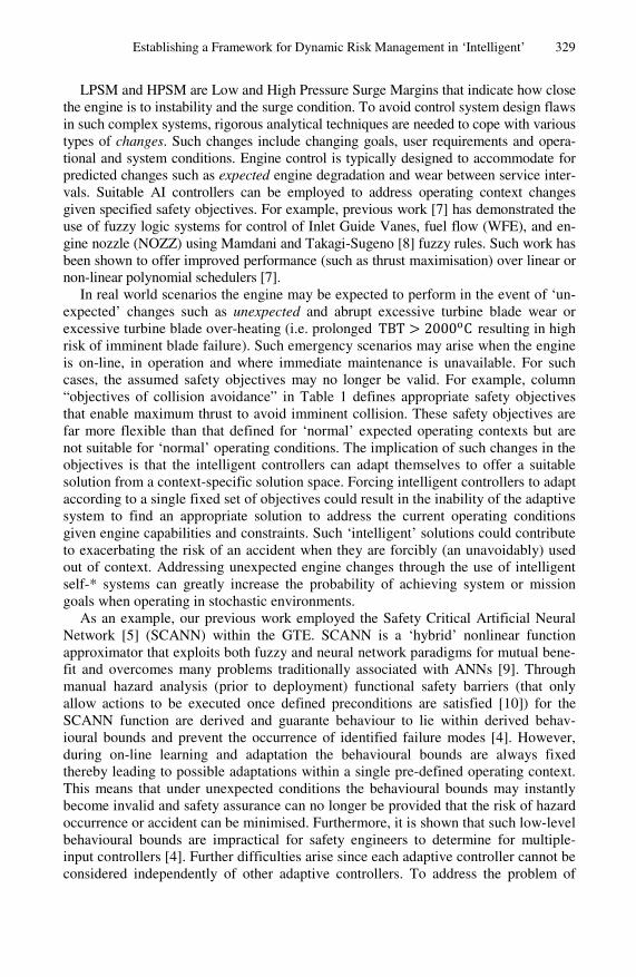
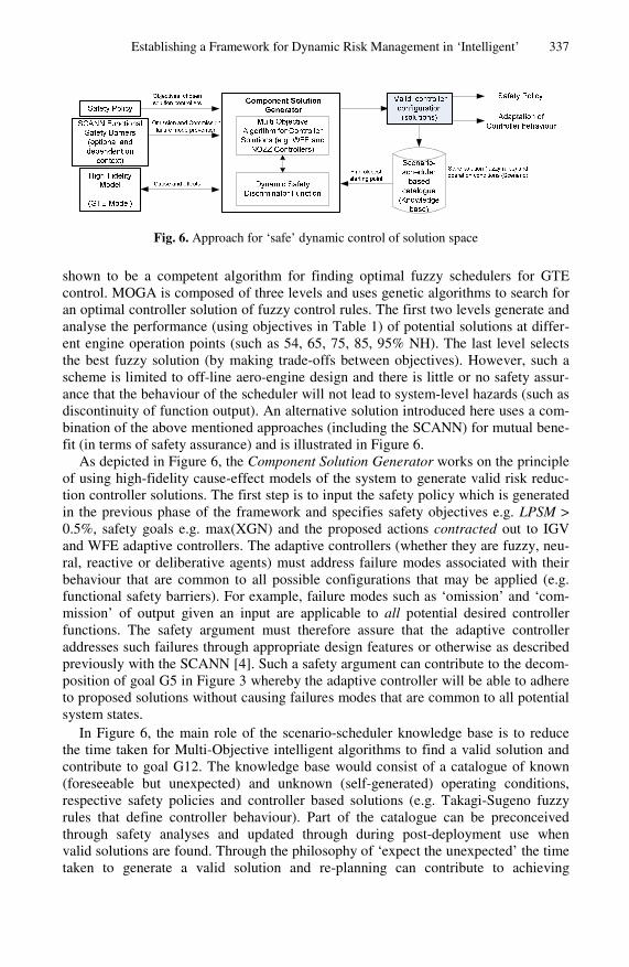
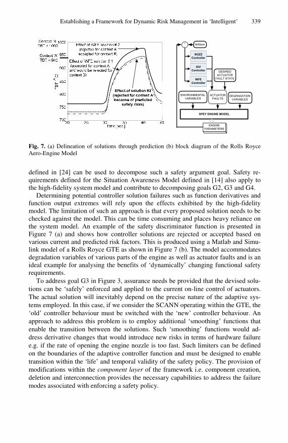
Fig. 7. (a) Delineation of solutions through prediction (b) block diagram of the Rolls Royce Aero-Engine Model
defined in [24] can be used to decompose such a safety argument goal. Safety re-quirements defined for the Situation Awareness Model defined in [14] also apply to the high-fidelity system model and contribute to decomposing goals G2, G3 and G4.
Determining potential controller solution failures such as function derivatives and function output extremes will rely upon the effects exhibited by the high-fidelity model. The limitation of such an approach is that every proposed solution needs to be checked against the model. This can be time consuming and places heavy reliance on the system model. An example of the safety discriminator function is presented in Figure 7 (a) and shows how controller solutions are rejected or accepted based on various current and predicted risk factors. This is produced using a Matlab and Simu-link model of a Rolls Royce GTE as shown in Figure 7 (b). The model accommodates degradation variables of various parts of the engine as well as actuator faults and is an ideal example for analysing the benefits of ‘dynamically’ changing functional safety requirements.
To address goal G3 in Figure 3, assurance needs be provided that the devised solu-tions can be ‘safely’ enforced and applied to the current on-line control of actuators. The actual solution will inevitably depend on the precise nature of the adaptive sys-tems employed. In this case, if we consider the SCANN operating within the GTE, the ‘old’ controller behaviour must be switched with the ‘new’ controller behaviour. An approach to address this problem is to employ additional ‘smoothing’ functions that enable the transition between the solutions. Such ‘smoothing’ functions would ad-dress derivative changes that would introduce new risks in terms of hardware failure e.g. if the rate of opening the engine nozzle is too fast. Such limiters can be defined on the boundaries of the adaptive controller function and must be designed to enable transition within the ‘life’ and temporal validity of the safety policy. The provision of modifications within the component layer of the framework i.e. component creation, deletion and interconnection provides the necessary capabilities to address the failure modes associated with enforcing a safety policy.
340 Z. Kurd et al.
5 Conclusions
This paper has shown the challenges of exposing ‘intelligent’ adaptive systems to unexpected operating conditions in the context of a highly dynamical and complex problem domain. The presented self-management framework identifies key activities and shows how they contribute to the dynamic risk management safety argument. The framework has shown how behaviour-based approaches for generating safety argu-ments are highly reliant on the provision of high-fidelity models. Through the frame-work, low level component solutions are shown to be highly dependent on the man-agement of a hierarchy of goals and constraints. Also outlined is how features of the framework enable controller solutions to be generated on-line and how prediction and historical knowledge base can contribute to addressing identified safety challenges such as validity and non-functional resources. Much work remains for a complete solution and the focus of remaining work includes the provision of safety assurance for automated safety policy generation, high-fidelity modelling and employing a multi-agent architecture for problem solving that would enable a highly scalable and modular solution.
Acknowledgements
The work described in this paper was funded by the EPSRC under the LSCITS (Large Scale Complex Information Technology Systems) programme. We are also grateful to Parta Dutta from SRC Rolls-Royce for providing useful domain knowledge.
References
1. IEC, 61508: Fundamental Safety of Electrical / Electronic / Programmable Electronic Safety Related Systems, International Electrotechnical Commission (1999)
2. Heo, J.S., Lee, K.Y.: A multi-agent system-based intelligent control system for a power plant. In: IEEE Power Engineering Society General Meeting, vol. 2, pp. 1050–1055 (2005)
3. Calinescu, R., Kwiatkowska, M.: Using quantitative analysis to implement autonomic IT systems. In: Proceedings of the 31st International Conference on Software Engineering (ICSE 2009), Vancouver, British Columbia, Canada (2009)
4. Kurd, Z.: Artificial Neural Networks in Safety Critical Applications, PhD Thesis, Depart-ment of Computer Science, University of York, York (2005)
5. Kurd, Z., Kelly, T.P.: Using Safety Critical Artificial Neural Networks in Gas Turbine Aero-Engine Control. In: Winther, R., Gran, B.A., Dahll, G. (eds.) SAFECOMP 2005. LNCS, vol. 3688, pp. 136–150. Springer, Heidelberg (2005)
6. Kurd, Z., Kelly, T.: Using Fuzzy Self-Organising Maps for Safety Critical Applications. Reliability Engineering & System Safety 92(11), 1563–1583 (2007)
7. Chipperfield, A.J., Bica, B., Fleming, P.J.: Fuzzy Scheduling Control of a Gas Turbine Aero-Engine: A Multiobjective Approach. IEEE Trans. on Indus. Elec. 49(3) (2002)
8. Sugeno, M., Takagi, H.: Derivation of Fuzzy Control Rules from Human Operator’s Con-trol Actions. In: Proc. of the IFAC Symp. on Fuzzy Information, Knowledge Representa-tion and Decision Analysis (1983)
Establishing a Framework for Dynamic Risk Management in ‘Intelligent’ 341
9. Kurd, Z., Kelly, T.P.: Safety Lifecycle for Developing Safety-critical Artificial Neural Networks. In: Anderson, S., Felici, M., Littlewood, B. (eds.) SAFECOMP 2003. LNCS, vol. 2788, pp. 77–91. Springer, Heidelberg (2003)
10. Hollnagel, E.: Accidents and Barriers. In: Proceedings of Lex Valenciennes, Presses Uni-versitaires de Valenciennes, pp. 175–182 (1999)
11. MoD, Defence Standard 00-56 Issue 3: Safety Management Requirements for Defence Systems, Issue 3, Part 2, UK Ministry of Defence (2004)
12. Austin, J.: A Grid Based Diagnostics and Prognosis System for Rolls Royce Aero Engines: The DAME Project. In: 2nd International Workshop on Challenges of Large Applications in Distributed Environments (CLADE 2004), Honolulu, Hawaii, USA. IEEE Computer Society, Los Alamitos (2004)
13. Stranjak, A., et al.: A multi-agent simulation system for prediction and scheduling of aero engine overhaul. In: Proceedings of the 7th international joint conference on Autonomous agents and multiagent systems, International Foundation for Autonomous Agents and Mul-tiagent Systems: Estoril, Portugal, pp. 81–88 (2008)
14. Wardzinski, A.: Safety Assurance Strategies for Autonomous Vehicle. In: Harrison, M.D., Sujan, M.-A. (eds.) SAFECOMP 2008. LNCS, vol. 5219, pp. 277–290. Springer, Heidel-berg (2008)
15. Subramanian, H., et al.: Designing safe, profitable automated stock trading agents using evolutionary algorithms. In: Proceedings of the 8th annual conference on Genetic and evo-lutionary computation, pp. 1777–1784. ACM, Seattle (2006)
16. Torrellas, G.A.S.: A Framework for Multi-Agent System Engineering using Ontology Domain Modelling for Security Architecture Risk Assessment in E-Commerce Security Services. In: Proceedings of 3rd IEEE International Symposium on Network Computing and Applications (NCA 2004), pp. 409–412. IEEE Computer Society, Cambridge (2004)
17. Kelly, T.P.: Arguing Safety – A Systematic Approach to Managing Safety Cases, Ph.D. Thesis, Department of Computer Science, University of York, York, UK (1998)
18. Andoga, R., Madarasz, L., Fozo, L.: Digital Electronic Control of a Small Turbojet Engine - MPM 20. In: Proceedings of International Conference on Intelligent Engineering Systems (INES 2008). IEEE, Miami (2008)
19. Bishop, P., et al.: Justification of smart sensors for nuclear applications. In: Winther, R., Gran, B.A., Dahll, G. (eds.) SAFECOMP 2005. LNCS, vol. 3688, pp. 194–207. Springer, Heidelberg (2005)
20. Magee, J., Kramer, J.: Self-Managed Systems: an Architectural Challenge. In: Interna-tional Conference on Software Engineering 2007 Future of Software Engineering, Wash-ington, DC, USA, pp. 259–268. IEEE Computer Society, Los Alamitos (2007)
21. Hall-May, M., Kelly, T.P.: Towards Conflict Detection and Resolution of Safety Policies. In: Proceedings of 24th International System Safety Conference, System Safety Society, Albuquerque, USA (2006)
22. Deb, K.: Non-linear Goal Programming Using Multi-Objective Genetic Algorithms, in Computational Intelligence, Universität Dortmund (2004)
23. Hall-May, M., Kelly, T.P.: Using Agent-based Modelling Approaches to Support the De-velopment of Safety Policy for Systems of Systems. In: Górski, J. (ed.) SAFECOMP 2006. LNCS, vol. 4166, pp. 330–343. Springer, Heidelberg (2006)
24. Alexander, R.: Using Simulation for Systems of Systems Hazard Analysis, PhD Thesis, Department of Computer Science, University of York, York (2007)