Embed Size (px)
Citation preview

ESA UNCLASSIFIED – For Official Use
estec European Space Research
and Technology Centre Keplerlaan 1
2201 AZ Noordwijk The Netherlands
T +31 (0)71 565 6565 F +31 (0)71 565 6040
www.esa.int
Vibration Induced Phenomena in Granular Materials (VIP-GRAN) for Parabolic Flight (PF) Experiment Scientific Requirements
Prepared by Olivier Minster Reference SCI-ESA-HSO-ESR-VIPGRAN-PF Issue 1 Revision 0 Date of Issue 31/01/2014 Status Under revision Document Type RQ Distribution HSO-US, HSO-UP

ESA UNCLASSIFIED – For Official Use
Title VIP-GRAN-PF Experiment Scientific Requirements
Issue 1 Revision 0
Author O. Minster Date 31/01/2014
Approved by Date
Science Team coordinators on behalf of the team members: Eric Falcon Nicolas Vandewalle Matthias Sperl
Physical Sciences Unit head: O. Minster
Page 2/37 VIP-GRAN-PF ESR Ref. SCI-ESA-HSO-ESR-VIPGRAN-PF Date 31/01/2014 Issue 1 Rev 0

ESA UNCLASSIFIED – For Official Use
Reason for change Issue Revision Date Original document 1 0 Issue for the UIB 2 0 11/01/2010 Issue further to the PDR 1 0 31/01/2014
Issue 1 Revision 0 Reason for change Date Pages Paragraph(s)
Applicable documents
AD 1 Human Spaceflight Data Policy, ESA/PB-HSR(2004)29, rev. 2, corr.1
Page 3/37 VIP-GRAN-PF ESR Ref. SCI-ESA-HSO-ESR-VIPGRAN-PF Date 31/01/2014 Issue 1 Rev 0

ESA UNCLASSIFIED – For Official Use
Table of Contents 1 INTRODUCTION ............................................................................................................................. 6 2 GENERAL DESCRIPTION ............................................................................................................... 7 2.1 Objectives ........................................................................................................................................................................... 7 2.2 Experiment Specific Objectives ......................................................................................................................................... 7 2.2.1 Principle of the experiment ............................................................................................................................................. 7 2.2.2 Granular gas (WP1).......................................................................................................................................................... 7 2.2.3 Cooling of granular gas (WP1).........................................................................................................................................8 2.2.4 Stress distribution in dense granular matter (WP2) ......................................................................................................8 2.2.5 Convection (WP3) ............................................................................................................................................................8 2.2.6 Segregation (WP4) ...........................................................................................................................................................8 2.2.7 Phase separation (Maxwell’s demon) (WP4)..................................................................................................................8 2.2.8 2D granular systems (WP1, WP2, WP4) .........................................................................................................................8 2.3 Experiment description ..................................................................................................................................................... 9 2.4 Justification of the need for space experiments ............................................................................................................... 9 2.5 Previous flight experiments (precursors)........................................................................................................................ 10 2.6 Reference publications ..................................................................................................................................................... 10 3 SCIENTIFIC REQUIREMENTS ON THE HARDWARE ..................................................................... 13 3.1 General concept ................................................................................................................................................................ 13 3.1.1 Concept for the cells ...................................................................................................................................................... 13 3.1.2 Characteristic dimensions of the cells .......................................................................................................................... 13 3.1.3 Observation requirements ............................................................................................................................................. 14 3.1.4 Excitation requirement .................................................................................................................................................. 14 3.2 Cell type “3D systems” characteristics ............................................................................................................................ 15 3.2.1 Dimensions .................................................................................................................................................................... 15 3.2.2 Piston roughness ............................................................................................................................................................ 15 3.2.3 Bead feeding device ....................................................................................................................................................... 15 3.2.4 Impact force sensors and accelerometers ..................................................................................................................... 15 3.3 Cell type “quasi-2D” characteristics ................................................................................................................................ 17 3.3.1 Dimensions .................................................................................................................................................................... 17 3.3.2 Bead feeding device ....................................................................................................................................................... 17 3.4 Cell type “3D systems with partition” characteristics ..................................................................................................... 18 3.4.1 Dimensions .................................................................................................................................................................... 18 3.4.2 Piston roughness ............................................................................................................................................................ 18 3.4.3 Freely mobile partition wall .......................................................................................................................................... 18 3.4.4 Bead feeding device ....................................................................................................................................................... 18 3.5 Cell type “Maxwell’s demon” characteristics ................................................................................................................. 20 3.6 Cell type “dense granular matter” characteristics .......................................................................................................... 21 3.6.1 Dimensions .................................................................................................................................................................... 21 3.6.2 Pressure .......................................................................................................................................................................... 21 3.6.3 Sound pulses generation and detection ........................................................................................................................ 21 3.6.4 Liquid tightness ............................................................................................................................................................. 22 3.6.5 Bead feeding device ....................................................................................................................................................... 22 3.7 Length of the active part of the cells ................................................................................................................................ 22 3.7.1 Length of the active part of the dry cells ....................................................................................................................... 22 3.7.2 Length of the active part of the wet cells ...................................................................................................................... 22 3.8 Bead feeding system ......................................................................................................................................................... 23 3.9 Requirements on the motion of the pistons .................................................................................................................... 23 3.9.1 Amplitude, frequency and acceleration of the pistons ................................................................................................. 23 3.9.2 Displacement accuracy .................................................................................................................................................. 24 3.9.3 Other shapes of oscillations ........................................................................................................................................... 24 3.10 Diagnostics requirements ................................................................................................................................................ 24 Page 4/37 VIP-GRAN-PF ESR Ref. SCI-ESA-HSO-ESR-VIPGRAN-PF Date 31/01/2014 Issue 1 Rev 0

ESA UNCLASSIFIED – For Official Use
3.10.1 Temperature measurements ......................................................................................................................................... 24 3.10.2 Zero-g plane acceleration measurements ..................................................................................................................... 24 3.10.3 Piston displacement measurements ............................................................................................................................. 24 3.10.4 Time synchronisation .................................................................................................................................................... 25 3.10.5 Impact force sensor ....................................................................................................................................................... 25 3.10.6 Accelerometers ............................................................................................................................................................... 26 3.11 Video requirements .......................................................................................................................................................... 26 3.11.1 Illumination level ........................................................................................................................................................... 26 3.11.2 Filming and lighting orientation ................................................................................................................................... 26 3.11.3 Depth of field ................................................................................................................................................................. 27 3.11.4 Field of view ................................................................................................................................................................... 27 3.11.5 Camera characteristics ................................................................................................................................................. 28 3.11.6 Image colour mode ....................................................................................................................................................... 28 3.11.7 Data acquisition ............................................................................................................................................................ 28 3.11.8 Real-time visualisation ................................................................................................................................................. 28 3.11.9 Image compression ....................................................................................................................................................... 28 3.11.10 Light polarisation .......................................................................................................................................................... 28 3.12 Fluids and materials......................................................................................................................................................... 29 3.12.1 Beads for dry cells .......................................................................................................................................................... 29 3.12.2 Beads and liquids for wet cells ...................................................................................................................................... 29 3.12.3 Cell and pistons materials ............................................................................................................................................ 30 4 SCIENTIFIC REQUIREMENTS ON OPERATIONS ........................................................................... 31 4.1 Experiment protocol ........................................................................................................................................................ 31 4.1.1 Protocol philosophy ....................................................................................................................................................... 31 4.1.2 Run Parameters ............................................................................................................................................................. 32 4.1.3 Cell fillings...................................................................................................................................................................... 32 4.1.4 Measurements ................................................................................................................................................................ 33 4.1.5 Protocol details .............................................................................................................................................................. 33 4.1.6 Ground reference experiment(s) ................................................................................................................................... 33 4.2 Science constraints during operational phases ............................................................................................................... 33 4.3 Communications requirements ....................................................................................................................................... 34 4.3.1 Requirements on commands ........................................................................................................................................ 34 4.3.2 Requirements on data downlink ................................................................................................................................... 34 4.3.3 Requirements on storage ............................................................................................................................................... 34 5 EXPERIMENT OUTPUTS .............................................................................................................. 35 6 ARRANGEMENTS ......................................................................................................................... 36 6.1 Deliverables ESA to science team .................................................................................................................................... 36 6.2 Deliverables science team to ESA .................................................................................................................................... 36 6.3 Publication and data sharing policy ................................................................................................................................ 36
Page 5/37 VIP-GRAN-PF ESR Ref. SCI-ESA-HSO-ESR-VIPGRAN-PF Date 31/01/2014 Issue 1 Rev 0

ESA UNCLASSIFIED – For Official Use
1 INTRODUCTION
Project ID: AO-2004-121 Title: Behaviour of Granular Dissipative Gas under Vibration and Cluster Formation (SPACEGRAINS) And ID: AO-2009-0943 Title: Compaction and Sound Transmission in Granular Matter (COMPGRAN) Acronym of the instrument: VIP-Gran-PF Team Members: Name Address email Eric Falcon Co-coordinator
CNRS-Université Paris Diderot Tel.: +33 1 57 27 62 19
Nicolas Vandewalle Co-coordinator
Dept Physique, University Liège, Belgium Tel.: +32 80 880 921
Matthias Sperl Co-coordinator
Institut für Materialphysik im Weltraum, DLR, Cologne Tel.: +49 (02203) 601-3434
Yves Garrabos CNRS-ICMCB, Pessac, France, Tel.: +33 5 40 00 63 37
Carole Lecoutre CNRS-ICMCB, CNRS Pessac, France [email protected]
Angel Garcimartín Montero
University Navarra, Pamplona, Spain Tel.: +34 948425600 ext. 6385
Diego Maza Ozcodi University Navarra, Pamplona, Spain [email protected] Meiying Hou IoP, CAS, Beijing [email protected] Pierre Evesque CNRS-Ecole Centrale Paris [email protected] Stephan Fauve Ecole Normale Supérieure [email protected] Sébastien Aumaitre CEA Saclay [email protected] Michaël Berhanu CNRS-Université Paris Diderot Michael.berhanu@univ-paris-
diderot.fr Robert Behringer Duke University [email protected] Eric Clement LMDH – PMMH [email protected] Stefan Luding Multi Scale Mechanics, Twente University [email protected] Matthias Schroeter Max Planck Institut für Dynamik und
Selbstorganisation [email protected]
Stefan Egelhaaf Univ. Düsseldorf [email protected] Axelle Amon Univ. Rennes [email protected] Jérôme Crassous Univ. Rennes [email protected] Douglas Durian Univ. Pennsylvannia [email protected] Xiaoping Jia LPMDI, Un. Marne la Vallée [email protected] Ralf Stannarius Otto van Guerike Univeristy Magdeburg [email protected] ESA project scientist: Olivier Minster, HSO-USP, [email protected] (+31-71 565 4764) ESA instrument project manager: Marco.Martella, HSO-UPM, [email protected] (+31-71 565 4846)
Page 6/37 VIP-GRAN-PF ESR Ref. SCI-ESA-HSO-ESR-VIPGRAN-PF Date 31/01/2014 Issue 1 Rev 0

ESA UNCLASSIFIED – For Official Use
2 GENERAL DESCRIPTION
2.1 Objectives The aim of SPACEGRAINS and COMPGRAN experiments is to study the dynamical and statistical properties of granular media in low-gravity environment, from dilute to dense regimes. It is of primary interest to better understand rheology, flow and dynamics of granular media subjected to vibrations. Beyond the spatial interest (management of a granular in space, of powder propellants of rockets, and better understanding of planetary ring dynamics), the motivation for low gravity is to achieve an experimental situation in which inelastic collisions between particles are the only interaction mechanism. The only time scale for such a granular system in low gravity is the period of vibrations that thus strongly simplifies the modelling of the system by using simple dimensional analysis. Long run experiments are also necessary since transient phenomena are of quite long duration for granular systems. The objective is to perform unique measurements on granular gas (clustering and phase transitions), convection, segregation and jamming in granular materials subjected to vibrations without the symmetry breaking influence of gravity.
2.2 Experiment Specific Objectives The specific objectives are to experimentally answer to basics questions: How a granular gas (which is intrinsically dissipative due to inelastic collisions) deviates from the elastic limit of usual gas when dissipation increases? What is the phase diagram of dynamical states of such an out-of-equilibrium dissipative gas? What is the spatial distribution of an applied mechanical stress or acoustic deformations within a granular without confinement pressure of grains due to their own weight? What is the large-scale dynamics of a dense granular medium mediated by a convection-like mechanism (when two walls vibrates with different velocities as a ‘‘thermal gradient’’-like forcing)? What is the segregation mechanism in a granular composed of two types of particle species in low gravity? For this purpose, systematic experiments have to be performed from dilute to dense regimes, as described below (see also http://spacegrains.org/ for recent updates).
2.2.1 Principle of the experiment The basic principle of the experiment consists in a 3D closed cell containing particles. Two opposite walls of the cell are pistons that vibrate in-phase or out-of-phase. Their opposite motion allows for injection of mechanical energy in the system. It is expected that the balance between this energy input and dissipative collisions of the particles will drive the system towards different stationary out-of-equilibrium regimes. Four different Working Packages (WP) have been selected. WP1: Dilute systems (granular gas), WP2: Dense systems, WP3: Convection, and WP4: Segregation and aspherical particles.
2.2.2 Granular gas (WP1) A dissipative granular gas differs from a usual gas due to the inelastic collisions between particles. Continuous injection of energy is thus necessary to sustain a stationary state in this dissipative out-of-equilibrium system. We will experimentally study how a granular gas deviates from the quasi-elastic limit (usual gas) when dissipation increases in the system. One way to do that is to increase the volume of the container at a constant particle density all things being equal. Another set
Page 7/37 VIP-GRAN-PF ESR Ref. SCI-ESA-HSO-ESR-VIPGRAN-PF Date 31/01/2014 Issue 1 Rev 0

ESA UNCLASSIFIED – For Official Use
of experiments will be devoted to quantify more precisely the clustering transition in order to establish the phase diagram between gas- and solid-like phases.
2.2.3 Cooling of granular gas (WP1) The study of the relaxation of a granular gas once the forcing is stopped will be also investigated. Such an experiment is hardly achievable on Earth due to the gravity restoring force, and need, in low-gravity, a very low level of g-jitter such as in ISS. Understanding of such a granular gas “cooling” is important for particle management in Space and to know how an out-of-equilibrium stationary system returns to equilibrium.
2.2.4 Stress distribution in dense granular matter (WP2) The behaviour of a granular material in dense regimes near the jamming transition is of particular interest at a fundamental and a more applied level. Without confinement pressure of grains due to their own weight, knowing the spatial distribution of stresses or acoustic deformations will be obtained by the use of stress-birefringent beads. In addition, sound (transmission and scattering) shall be measured both internally by stress-birefringence as well as by impact force sensors at the walls.
2.2.5 Convection (WP3) The large-scale dynamics of a dense granular medium mediated by a convection-like mechanism will be investigated. To mimic a “thermal gradient” forcing, two cell walls will vibrate with different velocities and phases. The corresponding “cold” and “hot” walls are expected to drive the system into a convective-like motion. The relevant parameter that controls convection is not yet established without confinement pressure of grains due to their own weight. Long runs are necessary since convective motions are quite slow.
2.2.6 Segregation (WP4) Another subject of interest is the segregation mechanism of binary mixtures (particle species of different sizes, shapes or densities). On Earth, segregation is frequently observed due to different mechanisms: convection by friction to boundaries, percolation of small particles under large ones known as “Brazil nuts” effect, etc. In absence of gravity, the segregation mechanism is unknown. Its knowledge will give new insights in the management of particles in weightlessness.
2.2.7 Phase separation (Maxwell’s demon) (WP4) In a dilute regime, the transfer of grains from a compartment to another connected by a slit shall be investigated. This experiment is also called a Maxwell’s demon experiment. This experiment shall study, in a dilute regime, how the transfer rate of grains varies with the volume fraction. With gravity, the phase separation is controlled by the ratio between the gravity potential energy at the altitude of the slit and the mean kinetic energy per particle. In absence of gravity, the mechanism of phase separation is an open problem.
2.2.8 2D granular systems (WP1, WP2, WP4) Similar experiments as in WP1, WP2 and WP4 will be performed in a quasi-2D cell. This cell enables much more simple tracking of each particle with one single camera than with respect to 3D cells.
Page 8/37 VIP-GRAN-PF ESR Ref. SCI-ESA-HSO-ESR-VIPGRAN-PF Date 31/01/2014 Issue 1 Rev 0

ESA UNCLASSIFIED – For Official Use
2.3 Experiment description As schematically shown in the figure below, the instrument consists of a 3D cell filled with particles where two opposite container walls act as vibrating pistons. Different cells will be used, split into different compartments or not, and will be interchangeable on the instrument. For instance, one cell is adjustable in length. Control parameters are the number of particles N, the cell length L, and the amplitude, a, and the frequency, f, of vibrations. Impact force sensors will be implemented to resolve collisions of particles on cell walls to notably deduce the experimental distributions of particle velocity, of time of flight between two successive collisions with a wall. Accelerometers screwed in the shaft of each vibrating piston will enable to infer mean injected power and the temporal fluctuation of injected power. Two cameras will enable to visualize the system, and perform quantitative measurements from particle tracking in dilute regime and correlations between particle displacements. Several experiments will be performed from dilute to dense fillings.
The typical protocol is as follows. At the beginning of a run, one shall “refresh” initial conditions by a slow (or rapid) motion of the pistons in some direction before starting vibrating at a definite amplitude and frequency. Then, different experiments are performed with various forcing parameters and filling (number of beads or type of bead).
2.4 Justification of the need for space experiments One of the most astonishing properties of granular matter under vibrations is its tendency to form clusters of particles. Although this has probably been known since the early observation of planetary rings, only few experiments have been performed which display cluster formation. Furthermore, ground based experiments are perturbed by gravity and by the coherent friction force which acts on all the particles and which is far from being negligible. Low-gravity environment is thus needed for dilute regimes of vibrated granular medium because it is the only way to achieve the experimental situation in which inelastic collisions are the only interaction mechanism. Low-gravity environment is also needed to better understand the rheology and the jamming transition of dense granular media without confinement pressure of grains due to their own weight. Weak mechanical or acoustic vibrations can be then applied to the granular medium to probe and control its rheology near the onset of jamming. The time scale for granular matter subject to vibrations to reach a steady state configuration or for mechanism such as segregation to be observed and the study of the transients to reach that configuration calls for long duration experiments in free-fall conditions. On top of acquiring statistically representative observations, the number of parameters that influence the state of granular matter requires to perform numerous consecutive experiments. The ISS is therefore the platform favoured for operating the VIP-Gran instrument. Preparatory work on the Parabolic Flights (PF) to test and
Impact force sensor
Piston 2 a2, f2
La
Accelerometer
Piston 1 a1, f1
High speed Camera 1
High speed Camera 2
Bronze or polyamide or glass beads
Page 9/37 VIP-GRAN-PF ESR Ref. SCI-ESA-HSO-ESR-VIPGRAN-PF Date 31/01/2014 Issue 1 Rev 0

ESA UNCLASSIFIED – For Official Use
validate the technical solutions for the complete system (instrument and cells) and get first sets of scientific results are however deemed to be extremely valuable.
2.5 Previous flight experiments (precursors) MiniTEXUS-5 This sounding rocket experiment was performed in 1998 in order to study granular media in low-gravity environment. It led to the first observation of clustering formation in a granular gas in low gravity due to the inelastic collisions between particles. Results were published in Physical Review Letters 83, 440 (1999) and were commented in the American scientific press (Science, Science News and Physics News in 1999) MAXUS-5 This follow-on experiment was carried out in 2003 to study the dilute regime of granular gases in low gravity. By means of 7 cells filled with different volume fractions, different phases of granular matter under vibration were observed such as gas-, liquid-, and solid-like phases. MAXUS-7 This sounding rocket mission took place in 2006. The cell was made of one 3D compartment (with visualization on two perpendicular directions), and of one 2D compartment. The goal was to confirm the formation of the 3D and 2D liquid-like clusters. REXUS-10 This sounding rocket was launched in 2011 to study a granular gas constituted of aspherical particles (rod-like). For such an anisotropic granular gas, the mean free path of particle is considerably reduced with respect to a granular gas of spherical particles at the same volume fraction. No clustering is observed and the principle of equipartition of kinetic energy between rotations and translations is violated. Results were published in Physical Review Letters 110, 144102 (2013). PARABOLIC FLIGHTS Parabolic flight experiments were performed by several of the members of the Science Team notably to prepare the above sounding rocket experiments. Some campaigns have shown the ability of impact force sensors to record the collision frequency and of the impulses on a container wall and to give access to several quantities of interest. For instance, contrary to usual gases, the mean collision frequency in a granular gas is found to not scale linearly with the number of particles in the container [see EPL 74, 830 (2006)]. This is due to the dissipative nature of the collisions and is also directly related to the non-extensive behaviour of the kinetic energy (the granular temperature is not intensive). In the parabolic flight campaign DLR-13 in 2009 (Sperl et al), the compaction was demonstrated for a dense stress-birefringent sample in three dimensions, cf. [P. Yu, A. Boerngen, S. Frank-Richter, and M. Sperl, Granular Matter, accepted for publication (2013)].
2.6 Reference publications E. Opsomer, M. Noirhomme, N. Vandewalle and F. Ludewig, Phys. Rev. E 88, 012202 (2013)
How dynamical clustering triggers Maxwell’s demon in microgravity
E. Falcon, J.-C. Bacri, and C. Laroche, EPL 103, 64004 (2013)
Equation of state of a granular gas homogeneously driven by particle rotations
K. Harth, U. Kornek, T. Trittel, U. Strachauer, S. Höme, K. Will, R. Stannarius, Phys. Rev. Lett. 110, 144102 (2013)
Granular gases of rod-shaped grains in microgravity
W. T. Kranz, M. Sperl, A. Zippelius, Phys. Rev. E 87, 022207 (2013),
The Glass Transition in Driven Granular Fluids: A Mode-Coupling Approach,
Page 10/37 VIP-GRAN-PF ESR Ref. SCI-ESA-HSO-ESR-VIPGRAN-PF Date 31/01/2014 Issue 1 Rev 0

ESA UNCLASSIFIED – For Official Use
M. Berhanu, A. Petroff, O. Devauchelle, A. Kudrolli, D.H. Rothman, Physical Review E 86 (2012)
Shape and dynamics of seepage erosion in a horizontal granular bed
T. Bertrand, C. Bonnoit, E. Clément, A. Lindner, Granular Matter 14, 169 (2012)
Dynamics of drop formation in granular suspensions: The role of volume fraction
G. A. Caballero-Robledo, C. Goldenberg, E. Clement, Granular Matter 14, 239 (2012)
Local dynamics and synchronization in a granular glass
A. Janda, I. Zuriguel and D. Maza, Phys. Rev. Lett. 108, 248001 (2012)
Flow Rate of Particles through Apertures Obtained from Self-Similar Density & Velocity Profiles
Y. Li, R. Liu, and M. Hou, Phys. Rev. Lett. 109, 198001 (2012)
Gluing bifurcation and noise-induced hopping in the oscillatory phenomena of compartmentalized bi-disperse granular
gases
Y. Li, R. Liu, M. Shinde, M. Hou, Granular Matter 14, 137 (2012)
Flux measurement in compartmentalized mono-disperse and bi-disperse granular gases
C. Lozano, A. Janda, A. Garcimartín, D. Maza and I. Zuriguel, Phys. Rev. E 86, 031306 (2012)
Flow and clogging in a silo with an obstacle above the orifice
C. Lozano, G. Lumay, I. Zuriguel, R.C. Hidalgo, A. Garcimartín, Phys. Rev. Lett. 109,068001 (2012)
Breaking Arches with Vibrations: The Role of Defects
E. Opsomer, F. Ludewig, and N. Vandewalle, EPL 99, 40001 (2012)
Dynamical clustering in driven granular gas
H. S. Sajjad, Y. Li, F. Cui, Q. Zhang, and M. Hou, Chin. Phys. B 21, No.1, P.014501 (2012)
Directed segregation in compartmentalized bi-disperse granular gas
H. S. Sajjad, Y. Li, F. Cui, Q. Zhang, and M. Hou, Chin. Phys. Lett. 29, No.3, P.034501 (2012) Irregular Oscillation of Bi-
disperse Granular Gas in Cyclic Three Compartments
M. Sperl, W.T. Kranz, A. Zippelius, EPL 98,28001 (2012)
Single-particle dynamics in dense granular fluids under driving
A. Tordesillas, D.M. Walker, G. Froyland, J. Zhang, R.P. Behringer, Phys. Rev. E 86, 011306 (2012) Transition dynamics
and magic-number-like behavior of frictional granular clusters
M.-J. Dalbe, D. Cosic, M. Berhanu, A. Kudrolli, Physical Review E 83, (2011)
Aggregation of frictional particles due to capillary attraction
C. Yanpei, P. Evesque, and M. Hou, Chin. Phys. Lett. 29, No.7, P.074501 (2012)
Breakdown of Energy Equipartition in Vibro-Fluidized Granular Media in Micro-Gravity
D. Bi, J. Zhang, B. Chakraborty, R.P. Behringer, Nature 480, 355 (2011)
Jamming by shear
A. Garcimartín, I. Zuriguel, A. Janda and D. Maza, Phys. Rev. E 84, 031309 (2011)
Fluctuations of grains inside a discharging two-dimensional silo
R. Harich, T. Darnige, E. Kolb, E. Clément, EPL 96, 54003 (2011)
Intruder mobility in a vibrated granular packing
T. Kanzaki, M. Acevedo, I. Zuriguel, I. Pagonabarraga, D. Maza, R.C. Hidalgo Eur. Phys. J. E 34, 133 (2011) Stress
distribution of faceted particles in a silo after its partial discharge
L. Kondic, X. Fang, W. Losert, C.S. O’Hern, R.P. Behringer, Phys. Rev. E 85, 011305 (2011) Microstructure evolution
during impact on granular matter
Page 11/37 VIP-GRAN-PF ESR Ref. SCI-ESA-HSO-ESR-VIPGRAN-PF Date 31/01/2014 Issue 1 Rev 0

ESA UNCLASSIFIED – For Official Use
Y. Li, M. Hou, and P. Evesque, J. Phys. Conf. Ser. 327, 01203 (2011)
Directed clustering in driven compartmentalized granular gas systems in zero gravity
V.B. Nguyen, T. Darnige, A. Bruand, E. Clement, Phys. Rev. Lett. 107, 138303 (2011)
Creep and fluidity of a real granular packing near jamming
E. Opsomer, F. Ludewig and N. Vandewalle, Phys. Rev. E. 84, 051306 (2011)
Phase transitions in vibrated granular systems in microgravity
E. Opsomer, F. Ludewig and N. Vandewalle, J. Phys.: Conf. Ser. 327, 012035 (2011)
Dynamical regimes of a granular gas in microgravity: a molecular dynamics study
L. A. Pugnaloni, José Damas, I. Zuriguel, D. Maza, Papers in Physics 3, 030004 (2011)
Master curves for the stress tensor invariants in stationary states of static granular beds. Implications for the
thermodynamic phase space
C. Yanpei, P. Evesque, M. Hou, C. Lecoutre, F. Palencia, Y. Garrabos, J. Phys. Conf. Ser 327, 012033 (2011)
Long range boundary effect of 2D intermediate number density vibro-fluidized granular media in micro-gravity
I. Zuriguel, A. Janda, A. Garcimartín, C. Lozano, R. Arévalo, D. Maza, Phys. Rev. Lett. 107, 278001 (2011) Silo Clogging Reduction by the Presence of an Obstacle
Page 12/37 VIP-GRAN-PF ESR Ref. SCI-ESA-HSO-ESR-VIPGRAN-PF Date 31/01/2014 Issue 1 Rev 0
ESA UNCLASSIFIED – For Official Use
3 SCIENTIFIC REQUIREMENTS ON THE HARDWARE
Each requirement has been prioritised as follows: Priority 1 is essential (unless otherwise specified, requirements are Priority 1) Priority 2 is optimal Priority 3 is nice to have
Justifications and/or comments are provided for explanation and information. List of parameters: Symbol Unit Denomination a mm amplitude of a stimulus d mm diameter of a bead D mm depth of the cell H mm height of the cell L mm total inner length of the cell hosting the experiment La mm length of the experimentally active part of the cell
(the one that contains the beads) Ra Hz frame rate of the camera f=w/2π Hz frequency of a stimulus θ rad phase of the oscillation
3.1 General concept The requirements for different cells are provided below. The cell geometry as well as the stimuli characteristics depend of the studied phenomena. The different configurations are then detailed.
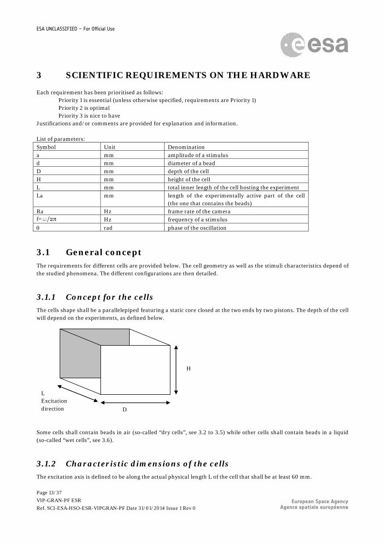
3.1.1 Concept for the cells The cells shape shall be a parallelepiped featuring a static core closed at the two ends by two pistons. The depth of the cell will depend on the experiments, as defined below.
Some cells shall contain beads in air (so-called “dry cells”, see 3.2 to 3.5) while other cells shall contain beads in a liquid (so-called “wet cells”, see 3.6).
3.1.2 Characteristic dimensions of the cells The excitation axis is defined to be along the actual physical length L of the cell that shall be at least 60 mm.
H
D
L Excitation direction
Page 13/37 VIP-GRAN-PF ESR Ref. SCI-ESA-HSO-ESR-VIPGRAN-PF Date 31/01/2014 Issue 1 Rev 0

ESA UNCLASSIFIED – For Official Use
The length La of the active part of the cell that actually confines the beads shall be selectable (see 3.7). The depth of each cell is specific for each cell and shall be fixed. The inner height of each cell shall be 30 mm.
3.1.3 Observation requirements The observation system shall enable the recording of video sequences with a field of view including the full active volume of the cell (that is the volume occupied by the beads including the walls that confine them).
3.1.4 Excitation requirement It shall be possible to activate the pistons at independent frequency and amplitude (see section 3.9.1). A controllable phase shift between the pistons is assumed. The shape of the stimuli shall be a modifiable parameter (see section 3.9.3). The surface roughness of the pistons shall be selectable (either smooth or roughened, see 3.2.2). Justification: The weight of the moving mass is strongly reduced with respect to moving the entire cell. Both pistons will be driven at different frequencies, or at the same frequency, either in phase (θ1=θ2) or out of phase (θ1≠0≠θ2), or in opposite phase (θ1-θ2=±π), with same or different amplitudes a1, a2 of vibration and frequencies f1=ω1/(2π), f2=ω2/(2π) of vibration. Comments: The case f1=f2, a1=a2 and θ1=θ2 is interesting since it limits the vibration transmitted to the ISS. Since θ can vary with time t, care has to be taken to impose enough space remaining in the cell for the granular matter all along during shaking. This can be ensured using a piezoelectric sensor which measures the force on each piston in order to detect a strong increase of force. The pistons could move at will according to, typically, a sinusoid with varying amplitude and frequency range within the limits defined in 3.9.1.
Piston 1 Frequency f1 Amplitude a1
Piston 2 Frequency f2 Amplitude a2
L
H
Page 14/37 VIP-GRAN-PF ESR Ref. SCI-ESA-HSO-ESR-VIPGRAN-PF Date 31/01/2014 Issue 1 Rev 0

ESA UNCLASSIFIED – For Official Use
3.2 Cell type “3D systems” characteristics
Schematic of cell type “3D systems” (dimensions in mm)
3.2.1 Dimensions Cell with a fixed square section (30mm x 30mm) The cell type “3D systems” shall have the following dimensions: H= 30 mm D= 30 mm L= 60 mm
3.2.2 Piston roughness The surface roughness of the piston shall be selectable (either smooth or with a roughness of the order of the grain size in both height and lateral extent). In a given cell, both pistons shall feature the same surface characteristics. The parameters describing the roughness are the following ones: TBD
3.2.3 Bead feeding device Up to two bead feeding device(s) (see 3.8) are required to add to a given volume fraction of monodisperse beads additional beads of different size or shape.
3.2.4 Impact force sensors and accelerometers Both pistons shall each be equipped with an impact force sensors on the piston wall (see 3.10.5) and an accelerometer on the shaft (see 3.10.6)
Page 15/37 VIP-GRAN-PF ESR Ref. SCI-ESA-HSO-ESR-VIPGRAN-PF Date 31/01/2014 Issue 1 Rev 0

ESA UNCLASSIFIED – For Official Use
Justification for this cell type: The aim is to study dynamical states of granular gases as well as segregation effects in a dilute regime (WP1 and WP4). In a dense regime, the cell can be used to study convection-like motions induced by vibration (WP3). Roughening the piston aims to deliver a more stochastic spatial forcing than smooth pistons do. Control parameters will be the number of beads, the amplitude and frequency of the forcing, and the cell length. By means of cameras, impact force sensors and accelerometers, particle tracking and correlations, local density, collision frequency, velocity distribution, mean injected power and its fluctuations will be inferred. Implementing two bead feeders enables the study of the competition of two different particle species. Clustering may occur for one species, the other one remaining in a gas state. The presence of a second species may therefore induce clustering, which is of high interest. Segregation is expected when both species form a cluster in the middle of the cell, which can be investigated by optical means. The accelerometers on the pistons’ shaft enable to measure the acceleration of each piston, and thereby its velocity by numerically integrating the signal. This will provide the mean power injected by the piston into the system as well as temporal fluctuations of injected power due to the bead collisions on the piston. Both quantities are of primary interest to describe systems driven far from equilibrium such as granular gases. Comments: When pistons apply a mean stress, one can also use the cell with a sound emitter at a piston and a sound detector on the other piston to study sound transmission through a dry granular medium (WP2). If this mean stress varies slowly with time oscillating around an average, one can study the effect of small variations on the speed of sound. The suitability of the piston driver and the impact force sensor to perform such measurements should be assessed.
H
Beads
Piston
Cell
Page 16/37 VIP-GRAN-PF ESR Ref. SCI-ESA-HSO-ESR-VIPGRAN-PF Date 31/01/2014 Issue 1 Rev 0

ESA UNCLASSIFIED – For Official Use
3.3 Cell type “quasi-2D” characteristics
Schematic of cell type “quasi-2D” (dimensions in mm)
3.3.1 Dimensions The cell type “quasi-2D” shall have the following dimensions: H= 30 mm D= 5 mm L= 60 mm
3.3.2 Bead feeding device A bead feeding device (see 3.8) is required (Priority 2) to add to a given volume fraction of mono-disperse beads additional beads of different size or shape (if compatible with the bead feeding device). Justification for this cell type: Similar experiments as in WP1, WP2 and WP4 will be performed in a “quasi-2D” cell. The “quasi-2D” cell enables much simpler tracking of each particle with one single camera than in the case of “3D systems” cells.
30
60
5
Excitation axis
D
Page 17/37 VIP-GRAN-PF ESR Ref. SCI-ESA-HSO-ESR-VIPGRAN-PF Date 31/01/2014 Issue 1 Rev 0

ESA UNCLASSIFIED – For Official Use
3.4 Cell type “3D systems with partition” characteristics All details pertaining to this cell type are applicable for the purpose of a design concept study only.
Schematic of cell type “3D systems with partition” (dimensions in mm)
3.4.1 Dimensions Cell with a square section (30mm x 30mm) The cell type “3D systems with partition” shall have the following dimensions: H= 30 mm D= 30 mm L= 60 mm
3.4.2 Piston roughness The surface roughness of the piston shall be selectable (either smooth or with a roughness of the order of the grain size in both height and lateral extent). In a given cell, both pistons shall feature the same surface characteristics. The parameters describing the roughness are the following ones: TBD
3.4.3 Freely mobile partition wall A partition parallel to the pistons but freely mobile shall be accommodated around the centre of the cell, with dimensions such that beads cannot cross over. It shall be possible to implement different partition inertia in the range TBD. The maximum friction (static, and dynamic) for its translational movements shall be TBD.
3.4.4 Bead feeding device A bead feeding device is required on each side of the mobile partition wall to locally change the bead volume fraction or to add beads of different size or shape (if compatible with the bead feeding device, see 3.8)
30
60
30
Excitation axis
30
Page 18/37 VIP-GRAN-PF ESR Ref. SCI-ESA-HSO-ESR-VIPGRAN-PF Date 31/01/2014 Issue 1 Rev 0

ESA UNCLASSIFIED – For Official Use
Justification for this cell type: To test the granular effective temperature on each side of the partition for cases where the number and type of grains are different on both sides of the partition. Since the number of grains is far smaller than the thermodynamic limit, the partition position will fluctuate. This will be measured and compared to the simple Gaussian expectation. The partition kinetic energy will be compared with the granular effective temperatures. Priority 2
Page 19/37 VIP-GRAN-PF ESR Ref. SCI-ESA-HSO-ESR-VIPGRAN-PF Date 31/01/2014 Issue 1 Rev 0

ESA UNCLASSIFIED – For Official Use
3.5 Cell type “Maxwell’s demon” characteristics Not applicable.
Page 20/37 VIP-GRAN-PF ESR Ref. SCI-ESA-HSO-ESR-VIPGRAN-PF Date 31/01/2014 Issue 1 Rev 0

ESA UNCLASSIFIED – For Official Use
3.6 Cell type “dense granular matter” characteristics This cell type is dedicated to the study of dense clouds of beads.
Schematic of the cell type “dense granular matter”
3.6.1 Dimensions The cell type “dense granular matter” shall have the following dimensions: H= 30 mm D= 30 mm L= 60 mm
3.6.2 Pressure The average pressure inside the cell can be the same as the ambient pressure. The design of the cell shall however limit the amplitude of pressure fluctuations in the liquid upon 10% compaction to less than 5% of the average pressure. This design requirement can be verified on the ground so that it is not required to monitor the cell pressure in space.
3.6.3 Sound pulses generation and detection A shock wave shall be generated at the location of one piston and shall be detected at the location of the other piston in order to measure the time of flight. The shock wave can be characterised as a single pulse corresponding to a one oscillation cycle with an acceleration of the piston of typically 4g for a duration of 20ms and return of the piston to the initial position with similar characteristics. Comment: The generation of sound pulses across the beads could make use of the piston position control capability (see 3.9.1). It should be verified if an impact force sensor (see 3.10.5) can suitably detect the transmitted sound pulse at the other piston. In a recent parabolic flight experiment, scientists at DLR made use of a pressure compensation device to limit pressure changes in the liquid upon compaction of the beads
H
Piston
Contained liquid
Piston
Page 21/37 VIP-GRAN-PF ESR Ref. SCI-ESA-HSO-ESR-VIPGRAN-PF Date 31/01/2014 Issue 1 Rev 0

ESA UNCLASSIFIED – For Official Use
3.6.4 Liquid tightness The cell shall provide for full containment of the liquid. The cell shall be filled without bubbles in the liquid.
3.6.5 Bead feeding device This cell does NOT require a bead feeding device Justification for this cell type: the birefringent beads are immersed in an index matching liquid and observed with linearly polarised light to reveal the distribution of stresses in the pack. Controlled compaction along with stimulation of the beads by sound pulses from one end of the cell and sound measurements at the other end will enable to study how sound waves propagate in the pack and how fast.
3.7 Length of the active part of the cells
3.7.1 Length of the active part of the dry cells The length of the active part, ‘La’, of the dry cells (cell types “3D systems”, “quasi-2D”, “3D systems with partition” and “Maxwell’s demon”) shall be adjustable at will by moving the mean position of each piston, such that:
• when the pistons are fully retracted, La ≥ 60mm, and • when the pistons are fully extended, La ≤ 5 mm.
For the cell type “Maxwell’s demon”, the piston shall not come any closer to the partition walls than 1.5 times the diameter of the biggest beads present in the cell. Justification: Changing the length of the active part of the cell enables to change the volume fraction of the beads without changing the number of beads. For the cell type Maxwell’s Demon, the distance between the piston and the partition walls is required to allow the exchange of beads between compartments. Resetting the experiment will be performed by applying a “thermal gradient” across the length of the cell (accumulation of the beads on the cold side).
3.7.2 Length of the active part of the wet cells The length of the active part, ‘La’, of the wet cells (cell type “dense granular matter”) shall be adjustable at will by moving the mean position of each piston, such that:
• when the pistons are fully retracted, La ≥ 50 mm, and • when the pistons are fully extended, La ≤ 30 mm.
The level of compaction of the beads will be controlled by controlling the positions of the pistons (see 3.10.3).
Page 22/37 VIP-GRAN-PF ESR Ref. SCI-ESA-HSO-ESR-VIPGRAN-PF Date 31/01/2014 Issue 1 Rev 0

ESA UNCLASSIFIED – For Official Use
3.8 Bead feeding system It shall be possible to increase, in a controlled manner1, the number of beads inside some cells (see characteristics of cell types above) in an incremental fashion. The numbers of beads to be added in a controlled manner shall be selectable between Nmini and Nmaxi beads at a time. The bead feeding system shall be able to inject spherical bronze and polyamide beads of Ø2mm (priority 1). This system shall also be tested with beads of Ø1mm (priority 2) A bead feeder shall enable to inject large numbers of beads, Nmini = 10 beads; Nmaxi = 250 beads of Ø2mm (priority 1) or 1000 beads of Ø1mm (priority 2). When adding any number of beads up to 100 beads, the tolerance shall be +/-2 beads. When adding any number of beads above 100 beads, the tolerance shall be +/-2% of the added number. A bead feeder of individual beads (Nmini = Nmaxi = 1 bead) is nice to have (priority 3). The maximum volume fraction of beads in a dry cell equipped with a bead feeding system will not exceed 50% (that means that when packed in FCC arrangement, the beads effectively occupy half of the maximum possible active volume of the cell). Objective: To study the effect of volume fraction in both dilute and dense systems. To study segregation effects between beads of different diameter by way of adding beads of a different diameter. To study segregation effects between beads by way of addition beads of a different diameter or different shape.
3.9 Requirements on the motion of the pistons
3.9.1 Amplitude, frequency and acceleration of the pistons
3.9.1.1 Amplitude The amplitude ‘a’ shall be selectable between 0.2 and 25 mm peak-to-peak. Comment: If it is possible to achieve amplitudes below 0.2 mm, the Science Team will make use of this capability within the limitations of the instrument.
3.9.1.2 Frequency The frequencies of vibration of the two moving/oscillating pistons shall be selectable between 1 and 50 Hz. It shall be possible to operate the pistons at different frequencies (asymmetric oscillations) within the microgravity perturbations limits allowed by the instrument and its accommodation constraints. Comment: In the great majority of experiments, the pistons will be driven at the same frequency and in phase shift of π.
1 i.e. selectable numbers of additional beads, at controlled times (while the pistons are not in motion) Page 23/37 VIP-GRAN-PF ESR Ref. SCI-ESA-HSO-ESR-VIPGRAN-PF Date 31/01/2014 Issue 1 Rev 0

ESA UNCLASSIFIED – For Official Use
3.9.1.3 Accelerations During an experiment run, the accelerations of the oscillating pistons shall range from 0 to 5g. This means that the relation between frequency and amplitude shall satisfy the condition: a.(2.π.f)2<5 g=50 m/s2. However it shall be possible to apply larger accelerations to the piston (up to 10 g) in order to destroy any structure of the beads in the cell and re-initialize the experiment (“refresh” run). In fact, the maximum acceleration of the pistons shall be determined such that the amplitude of each of them will depend on the acceleration and the frequency. The ability of the system to produce singular pulses should be determined, particularly for the generation of sound pulses in cell type “dense granular matter” (see 3.6.3).
3.9.2 Displacement accuracy For sinusoidal oscillations, the difference in position of any piston as measured by the observation system shall at no time deviate from an ideal sinusoidal displacement curve by more than ±0.2 mm, with the assumption that the origin of both curves is taken at the point of maximum speed of the piston (i.e. the zero displacement line of the theoretical curve).
3.9.3 Other shapes of oscillations Beyond sinusoidal oscillations at different amplitudes and frequencies per 3.9.1.3, the system shall also enable periodic non-sinusoidal oscillations as well as single pulses Comment: Ground tests should be performed to characterise the full capabilities of the system including the defining parameters (e.g. frequency, amplitude) for non-sinusoidal periodic oscillations and single pulses, with respect to the above-mentioned capabilities
3.10 Diagnostics requirements
3.10.1 Temperature measurements The cell temperature shall be known. The temperature shall be measured on the internal or external wall of the cell with an accuracy of less than 1 K.
3.10.2 Zero-g plane acceleration measurements A three-axis acceleration measurement located at a position close to the experiment cell shall be provided so as to measure the background acceleration of the zero-g plane when experiments are running in VIP-Gran-PF. The positioning of the accelerometer shall be such that there is no appreciable attenuation/amplification with respect to the experiment cell accelerations in the frequency range of interest. The frequency range for the acceleration measurement shall be between 1Hz and 1000Hz. The required resolution of the acceleration measurement is 10-6 g0.
3.10.3 Piston displacement measurements The position of the pistons shall be known to an accuracy better than 10-2 mm. The acquisition rate shall be above 1000Hz for each piston.
Page 24/37 VIP-GRAN-PF ESR Ref. SCI-ESA-HSO-ESR-VIPGRAN-PF Date 31/01/2014 Issue 1 Rev 0

ESA UNCLASSIFIED – For Official Use
Comments: This implies that the position of each piston is coded with 12 bits since 4096 is greater than 30 mm/0.01 mm.
3.10.4 Time synchronisation The time-tagging of data, such as acceleration data, piston force, impact force sensors, shall be synchronised with the image acquisition and the piston displacement with a resolution better than 10-4 sec.
3.10.5 Impact force sensor Two impact force sensors consisting of disk-shaped piezoelectric devices are required (one on each vibrating wall) for the cells of types “3D systems” and “3D systems with partition”. The sensing surface could be fixed behind each vibrating wall on the vibrating piston. The sensor axis being collinear with the vibration axis. The sensor shall be able to resolve the collision of one bead impacting on it lasting typically five microseconds. To accurately describe the peak duration and amplitude, at least 10 points shall be recorded for one collision, i.e. a minimum sampling rate of 2MHz is needed (10 / 5µs = 2MHz).
Schematic of the disposition of impact force sensors Objective: To resolve the collisions of beads on the vibrating walls of the cell. To count the amplitude and the number of impacts. To infer the distribution of particle velocity near a wall, and the distribution of time of flight between two successive collisions with a wall. Comment: The Science Team has experience with piezoelectric devices with a sensing surface diameter of 12.7 mm with a sensitivity better than 11V/kN (±15%). In order to strongly reduce the amount of relevant data to be downlinked or stored to typically 10 kHz, an analogic filtering of the sensor output may also be proposed in coordination with the Science Team. The filtering stages are made
Excitation axis
Piston
Impact force sensors
Page 25/37 VIP-GRAN-PF ESR Ref. SCI-ESA-HSO-ESR-VIPGRAN-PF Date 31/01/2014 Issue 1 Rev 0

ESA UNCLASSIFIED – For Official Use
of an offset cancelling (to remove the continuous component of the signal), a notch filter near the forcing frequency ± few Hz (to remove residual sensitivity of the sensor to vibrational acceleration), and a Hilbert filter (to detect the envelope of the signal of each impact).
3.10.6 Accelerometers Two accelerometers are required to be fixed on the shafts of the pistons for the dry cells “3D systems”, "quasi-2D" and “3D systems with partition” to measure the acceleration of each piston in the direction of vibration, and also its velocity (by numerically integrating the acceleration signal), and thus to infer the mean power injected by each piston in the system as well as temporal fluctuations of injected power due to the bead collisions on the piston. The accelerometer shall be able to resolve the collision acceleration of one bead impacting on the piston lasting typically five microseconds. To accurately describe the peak duration and amplitude, it shall be possible to record at least 10 points for one collision; i.e. a minimum sampling rate of 2MHz is required (10 / 5µs = 2MHz). It shall be possible for the scientists to select the frequency at which these data are actually recorded during the run (between 1 kHz and 2 MHz) as part of the parameters set for a run. Objective: to measure accelerations of both pistons, and to infer the mean injected power by each piston (<P>=<F(t)xV(t)> force applied to the piston times the piston velocity) as well as the temporal fluctuations of injected power. The Science Team has positive experience with accelerometers with a sensitivity of the sensors between 0.1 V/g and 1 V/g (±10%) and a frequency range between 0.1 and 8000 Hz.
3.11 Video requirements
3.11.1 Illumination level The illumination level shall be sufficient to resolve the beads in any location in the cell. Comment: Back illumination is a common way to measure local densities. Particle tracking may require front illumination. Often, electronic devices provoke slight oscillations of light sources. Such oscillations should be avoided. Laboratory experiments make use of LED illumination.
3.11.2 Filming and lighting orientation Observation shall be made in 2 perpendicular directions, themselves perpendicular to the vibration axis. The observation directions are represented by the blue arrows on the schematic below. The cell shall be illuminated from the back. Front illumination (where the fast camera sits) shall also be foreseen. The illumination is schematically shown below by the red arrows.
Page 26/37 VIP-GRAN-PF ESR Ref. SCI-ESA-HSO-ESR-VIPGRAN-PF Date 31/01/2014 Issue 1 Rev 0

ESA UNCLASSIFIED – For Official Use
The direct reflection of the light to the observation camera shall be avoided. Bright spots on particles shall be avoided. The angle between the observation axis and the back/front illumination axis shall be between 0 and 90 degrees. It shall be possible for the scientists to select (see 4.3.1 and 4.3.2):
• which illumination and which camera is activated (one of the two or both), and • the intensity of the illumination on the basis of actual images delivered by the instrument.
Schematic of the illumination and observation requirements Justification: Two cameras with a corresponding illumination are important to visualize particle dynamics, and perform quantitative measurements from particle tracking in dilute regime and correlations between particle displacements. Comment: For particle tracking, two back light illuminations by LED located on the same axis as the one of the camera should make particles better appearing in dark on white background and similar conditions on both cameras.
3.11.3 Depth of field The depth of field shall be such that the entire depth of the cell can be observed at the resolution defined below for both the primary and secondary observation paths. Comment: The camera resolution (see section 3.11.5) should be high enough for resolving particles on pictures with the entire cell depth.
3.11.4 Field of view The field of view shall cover the full window during vibrations.
Primary observation axis
Back illumination
Front illumination at e.g. 45° angle Secondary observation axis
Excitation axis
Page 27/37 VIP-GRAN-PF ESR Ref. SCI-ESA-HSO-ESR-VIPGRAN-PF Date 31/01/2014 Issue 1 Rev 0

ESA UNCLASSIFIED – For Official Use
For viewing particles close to the front window, it shall be possible to digitally focus on smaller regions of interest (Priority 3)
3.11.5 Camera characteristics The frame rate of the camera shall be selectable between 1 and 1000 frames/s. The resolution of the camera shall be at least 1024 x 1024 pixels (particle diameter corresponding to 20-30 pixels). The selected zone to be acquired shall be selectable.
3.11.6 Image colour mode The pixels’ grey levels shall be recorded at minimum 8 bit resolution.
3.11.7 Data acquisition Data acquisition shall allow 3 Gbytes video recording in one single shot. The possibility of extending the acquisition of 1000 frame/s at full resolution for the whole duration of each zero-g parabola shall be assessed. Comment: One shot of 3Gbytes means for example 3 seconds of video recording at 1000 frames/s with 1000 x 1000 pixels resolution, or 3000 seconds at 1 frame/s and 1000 x 1000 pixels resolution, or 12000 seconds at 2 frames/s and 250 x 500 pixels resolution.
3.11.8 Real-time visualisation It shall be possible to visualise the real-time output of both cameras on a control screen during the experimental runs.
3.11.9 Image compression If a compression algorithm turns out to be necessary for data downlinking or storage purposes, it shall maintain the clear visibility of the beads outlines on the compressed images or videos.
3.11.10 Light polarisation Birefringence phenomenon enables to see the stress field. The visualisation of the stress induced light refraction by beads of cell type “dense granular matter” requires linear+ ¼ λ polarisers located on both sides of the cell (right circular polariser at the entrance and left circular polariser at the exit) (see schematic below). These polarisers can be laminated directly onto the windows of the cell.
Page 28/37 VIP-GRAN-PF ESR Ref. SCI-ESA-HSO-ESR-VIPGRAN-PF Date 31/01/2014 Issue 1 Rev 0

ESA UNCLASSIFIED – For Official Use
3.12 Fluids and materials
3.12.1 Beads for dry cells For dry cells, the beads shall be made of bronze or polyamide or glass and shall be spherical with a diameter as detailed in the Table 1 below. Bead type Particle shape Size Material M Medium sphere Ø1mm Bronze L Large sphere Ø2mm Bronze D Deformable sphere Ø1mm Polyamide G Sphere Ø1mm Glass
Table 1: Particles denominations
The beads shall be procured, characterised and provided to the project team by the members of the Science Team.
Purpose: Two different sizes are considered in order to test finite-size effects (through the ratio bead radius / cell size) dissipative mechanisms, as well as segregation phenomena (for mixtures). Medium and Large particles are made of a conducting solid material (bronze) which prevents the accumulation of electrical charges in the cell. The Polyamide and bronze spheres have different restitution coefficients, leading to possibly different dissipative phenomena. Additional bead types Hollow (H), Anisotropic (A) will undoubtedly be proposed if compatible with the instrument design. Anisotropic particles could be dimers or trimers (glued spheres) made of the same bronze material. Glass spheres will be employed primarily for sound propagation measurements in dense dry granular materials.
3.12.2 Beads and liquids for wet cells For cell type “dense granular matter”, the beads shall be made of stress birefringent material such as PDMS or PL-3.
Page 29/37 VIP-GRAN-PF ESR Ref. SCI-ESA-HSO-ESR-VIPGRAN-PF Date 31/01/2014 Issue 1 Rev 0

ESA UNCLASSIFIED – For Official Use
Spherical beads shall have a diameter of optimally 0.5 mm, however beads of 1 mm are also acceptable. Other shapes might be considered with their smallest features larger than 0.5 mm. The corresponding liquids with (partial) index matching shall be selected amongst the following mixtures:
• water/glycerol mixtures • water/ethanol mixtures • silicon oil • cassia oil • water/DMSO
The beads shall be procured, characterised and provided to the project team by the members of the Science Team
3.12.3 Cell and pistons materials The materials of the dry cells (types “3D systems”, “3D systems with partition”, “Maxwell’s demon” and “quasi-2D”) and of the corresponding pistons shall not lead to electrostatic charging of the beads. The cells shall be mounted on a grounded surface or attached to a grounding point such that all surfaces impacted by the beads shall be at ground potential. The material employed for the pistons shall optimally be the same as the materials of the beads present in the cell. The structure of the piston shall aim to minimise its deformation and its intrinsic vibrations caused by bead impacts. Justification: To avoid electrostatics as much as possible and dust deposition on the windows. Comment: The Science Team proposes to coat the cell with FTO (tin oxide with fluorine), used in the laboratory of Liège: http://www.solaronix.com/products/tcolayers/tco308/ The ageing of this material with respect to numerous bead-wall collisions should be tested.
Page 30/37 VIP-GRAN-PF ESR Ref. SCI-ESA-HSO-ESR-VIPGRAN-PF Date 31/01/2014 Issue 1 Rev 0

ESA UNCLASSIFIED – For Official Use
4 SCIENTIFIC REQUIREMENTS ON OPERATIONS
Definitions: A RUN is an experiment with one set of parameters of stimuli: frequency and amplitude of oscillations. See section 4.1.5 An EXPERIMENT is a series of RUNs with one configuration [cell type / bead type /bead volume fraction]. See section 4.1.5 Assumptions: The protocol hereafter assumes that:
• The cell and pistons are compliant with the requirements listed in the Chapter 3 • The bead feeding system allows to increase the number of beads • An on-board computer allows data treatment and video compression • It will be possible to control during in-flight operation the acquisition time, frame rate, illumination intensity
and run parameters. • Each zero-g parabola will enable to perform one run.
4.1 Experiment protocol
4.1.1 Protocol philosophy The protocol depends on the density (number of beads) and the phenomena to be studied (impact, sound propagation…). The different kinds of run are listed in the section 4.1.5
• Step 1, Runs: Explore the vibration domain by varying the density, the number of beads, the frequency and the amplitude.
• Step 2, Data treatment and Replay of step 1 with different parameters. Some data shall be downlinked (see section 4.1.5). The Science Team shall assess the preliminary results before an injection of beads, because the increase of beads is irreversible.
Figure 1: Timeline of one experiment
To be downloaded on ground: All recorded data
Piston oscillation
Image acquisition
Experiment timeline
Empty the camera buffer on the HD
HD
Page 31/37 VIP-GRAN-PF ESR Ref. SCI-ESA-HSO-ESR-VIPGRAN-PF Date 31/01/2014 Issue 1 Rev 0

ESA UNCLASSIFIED – For Official Use
Figure 2: After each experiment the particles number/size and/or the cell geometry is changed.
4.1.2 Run Parameters Run parameters Forcing parameters see 3.9.1 Fillings or volume fractions see 4.1.3
Particle types see 3.12.1 and 3.12.2
Table 2: Run parameters
4.1.3 Cell fillings The feeding system is defined in the section 3.8. However, the bead volume fraction can also be varied by changing the average positions of the opposite moving walls. The volume of the active part of the cell is then defined by the average distance between the opposite moving walls. One layer at rest corresponds to the number of beads covering the piston surface. For a 30 mm x 30 mm piston area, one layer is 900 beads (Ø1mm) or 225 beads (Ø2mm). Filling range
Volume fraction range
Number of fillings
Maximum number of beads
Tracking Comments
A 0.01 to 2 layers
12 1800 (Ø1mm) 450 (Ø2mm)
YES Particle tracking is used for this density.
B 0.5 to 6 layers
5 5400 (Ø1mm) 1350 (Ø2mm)
YES Particle tracking is used for this density.
C 15% to 40% 5 - NO Length of the active part of the cell can be varied to change the volume fraction
D Around 50%
3 - NO Length of the active part of the cell can be varied to change the volume fraction
Table 3: Cell fillings (volume fraction means ratio between total solid and gas)
Run1 Run2 Run 3
Cell/ Particles change
Experiment 1 …
Run1 Run2 Run 3 Experiment 2 …
Run1 Run2 Run 3 Experiment 3 …
Cell/ Particles change
… Experiment 4
Cell/ Particles change
Page 32/37 VIP-GRAN-PF ESR Ref. SCI-ESA-HSO-ESR-VIPGRAN-PF Date 31/01/2014 Issue 1 Rev 0

ESA UNCLASSIFIED – For Official Use
4.1.4 Measurements Three measurement methods are used: cameras, impact force sensors and accelerometers.
Cell type Image analysis*
Impact force sensors Accelerometers
Correlations Particle tracking “3D systems” YES YES YES YES “Quasi-2D” YES YES (1 camera) NO YES “Dense granular matter” TBC TBC NO NO
* to be performed on ground by members of the Science Team
Table 4: Diagnostics used for each cell
4.1.4.1 Video sequences frame rate Not applicable.
4.1.4.2 Intermediate mode Not applicable.
4.1.4.3 Fast mode Not applicable.
4.1.5 Protocol details Not applicable.
4.1.6 Ground reference experiment(s) Ground tests shall be performed on the image and video compression with representative sample cell (size, beads and pistons oscillations), and with a vertical excitation direction. Objective: To adapt the protocol with the duration of compression and the duration of camera buffer transfer to the storage disk.
4.2 Science constraints during operational phases Not applicable.
Page 33/37 VIP-GRAN-PF ESR Ref. SCI-ESA-HSO-ESR-VIPGRAN-PF Date 31/01/2014 Issue 1 Rev 0

ESA UNCLASSIFIED – For Official Use
4.3 Communications requirements
4.3.1 Requirements on commands During in-flight operation, it shall be possible to control:
• Choice of illumination and corresponding intensity • Stimuli characteristics: Amplitudes, shape, phase and frequency of each stimuli for each piston • Acquisition time, frame rate
4.3.2 Requirements on data downlink Not applicable.
4.3.3 Requirements on storage The data listed below shall be stored:
• The images / video (section 3.11) • Impact force sensors (section 3.10.5) • Accelerometers data (section 3.10.6 • Microgravity measurements (section 3.10.2) • Time (section 3.10.4) • Piston position (section 3.10.3) • Temperature measurements (section 3.10.1)
Page 34/37 VIP-GRAN-PF ESR Ref. SCI-ESA-HSO-ESR-VIPGRAN-PF Date 31/01/2014 Issue 1 Rev 0

ESA UNCLASSIFIED – For Official Use
5 EXPERIMENT OUTPUTS
Not applicable.
Page 35/37 VIP-GRAN-PF ESR Ref. SCI-ESA-HSO-ESR-VIPGRAN-PF Date 31/01/2014 Issue 1 Rev 0

ESA UNCLASSIFIED – For Official Use
6 ARRANGEMENTS
6.1 Deliverables ESA to Science Team ESA shall procure and own the complete set-up ready to be operated on the parabolic flights. The set-up will be made available by ESA to the different labs in different European countries according to a plan of tests coordinated within the science team and agreed upon by ESA, in order to enable the smooth preparation and realisation of flight experiments by the team members on ESA provided parabolic flight campaigns. ESA will organise the re-certification of the set-up for re-flights as required.
6.2 Deliverables Science Team to ESA The science team is responsible for the timely availability of the samples for the preparation of the flight experiments and the timely readiness for each campaign. The science team members are in charge of the logistics aspects relating to the preparation of the experiments and the participation to the campaigns.
6.3 Data sharing policy and Publication
The data policy defined in the document: Human Spaceflight Data Policy, ESA/PB-HSR(2004)29, rev. 2, corr.1 applies to this project.
The raw data are owned by ESA and the science team has a one-year exclusive right of access to these data. Therefore, the raw data collected by the team members who ran experiments during a specific campaign should be delivered to ESA. In parallel they should be made available by the same team members to all of the other members of the science team. Various types of analyses of flight data leading to complementary results can be proposed by different members and should be coordinated within the team. The data analysis plan and results publication approach should be defined and agreed by all team members with as principle objective to produce a first coordinated joint publication of the results. Subsequent publications should be presented to all team members for review and possible comments prior to their submission to a Journal. The team members commit to duly including appropriate acknowledgement of the contribution of ESA in all publications reporting on the microgravity experiments and/or the instrument/facility and results analyses, as well as to providing all publications to the ESA project scientist in PDF format. The team members also commit to providing a one-page summary of the results of each campaign for inclusion in the web-based Erasmus Experiment Archive, and to maintaining this summary up-to-date (summary of results and references of publications) as work progresses.
Page 36/37 VIP-GRAN-PF ESR Ref. SCI-ESA-HSO-ESR-VIPGRAN-PF Date 31/01/2014 Issue 1 Rev 0

ESA UNCLASSIFIED – For Official Use
Abbreviations and Acronyms AD Applicable Document BDC Baseline Data Collection COMPGRAN Compaction and Sound Transmission in Granular Matter DMSO Dimethyl sulfoxide ESA European Space Agency ESR Experiment Scientific Requirements ESTEC European Space Research and Technology Centre FCC Face Centred Cubic HSO Human Spaceflight and Operations ISS International Space Station N/A Not Applicable NASA National Aeronautics and Space Administration PB-HSR Human Spaceflight, Research and Applications Programme Board PDF Portable Document Format PDMS Polydimethylsiloxane PDR Preliminary Design Review PF Parabolic Flight PFC Parabolic Flight Campaign PL-3 Material for the stress birefringent beads (property of Vishey company) RD Reference Document SPACEGRAINS Behaviour of Granular Dissipative Gas under Vibration and Cluster Formation SPOT Science Payload and Operations Team TBC To Be Confirmed TBD To Be Determined UIB Utilisation Implementation Board VIP-Gran Vibration Induced Phenomena in Granular Materials
Page 37/37 VIP-GRAN-PF ESR Ref. SCI-ESA-HSO-ESR-VIPGRAN-PF Date 31/01/2014 Issue 1 Rev 0


![ESTEC Contract No. xxxxxxxxxx with [Contractor ...otri.us.es/otri/documentacion/convocatorias-internacional/Modelo de... · ESTEC Contract No. xxxxxxxxxx . with [Contractor] ... The](https://img.pdfslide.net/doc/110x75/5a9e6e1c7f8b9a6c178b5b53/estec-contract-no-xxxxxxxxxx-with-contractor-otriusesotridocumentacionconvocatorias-internacionalmodelo.jpg)