Embed Size (px)
Citation preview


ETAP Enterprise Solution
ETAP is the most comprehensive analysis platform for the design, simulation, operation, control, optimization, and automation of generation, transmission, distribution, and industrial power systems.
ETAP offers a suite of fully integrated software solutions including arc flash, load flow, short circuit, relay coordination, cable ampacity, transient stability, optimal power flow, and more. Its modular functionality can be tailored to fit the needs of any company, from small to large power systems.
Quality Assurance CommitmentETAP is Verified and Validated (V&V) against field results, real system measurements, established programs, and hand calculations to ensure its technical accuracy. Each release of ETAP undergoes a complete V&V process using thousands of test cases for each and every calculation module.
One-Line Diagram ........................ 4
Arc Flash Analysis ........................ 8
Short Circuit Analysis................. 13
Star - Device Coordination ......... 14
Load Analyzer ............................. 18
Switching Management ............. 19
Transient Stability Analysis ....... 20
Harmonic Analysis ..................... 21
Libraries ..................................... 21
Data Exchange ............................ 22
SmartPlant Interface ................. 23
Real-Time Server ....................... 24
Advanced Monitoring ................. 25
Real-Time Simulation ................ 26
Automatic Generation Control ... 27
Energy Accounting ..................... 28
Load Forecasting ........................ 29
Intelligent Load Shedding .......... 30
ETAP Support ............................. 31
System Requirements ............... 31
ETAP Quality Assurance program is specifically dedicated to meeting the requirements of:
ISO 9001:2008 A3147 UL10 CFR 50 Appendix B
10 CFR 21ANSI/ASME N45.2
ASME NQA-1ANSI/IEEE 730.1
CAN/CSA-Q396.1.2ANSI N45.22
2

3
etap.cometap.com
What’s New in ETAP 7.0
Release 7.0 of the ETAP Enterprise Solution brings design and analysis innovation to a new level of advancement and provides the platform upon which future ETAP innovation will follow. This release adds new powerful analysis modules and time-saving capabilities to the ETAP suite. This brochure highlights key functionality in Release 7.0 of ETAP, which encompasses a broad and robust set of new features and enhancements.
Modules x Base Package
x Load Flow Analysis
x Arc Flash Analysis
x Transient Stability
x Harmonic Analysis
x Star Device Coordination / Selectivity
x Star Sequence-of-Operation
x Data Exchange
ETAP Real-Time x Real-Time Server
x Advanced Monitoring
x Real-Time Simulation
x Automatic Generation Control
x Energy Accounting
x Load Forecasting
x Intelligent Load Shedding
Templates
One-Line Diagram x Auto-Select
x Keyboard Shortcuts
x Symbol Library
Load Analyzer
Single-Phase Arc Flash
Arc Flash Analyzer
Switching Management
Libraries x Solid State Trip Devices
x Cable
x Transmission Line
x Relay
x Battery
Delivering Unmatched
Speed, Precision, & Reliability
ETAP Real-Time Brochure
View the brochure online at etap.com for details on all ETAP Real-Time modules.

Let ETAP Auto-SelectDo the Work for You
+ Click
One-Line Diagram
ETAP One-Line Diagram is a user-friendly interface for creating and managing the network database used for schematic network visualization. You can interactively model, monitor, and manage the electrical network as well as execute simulation scenarios and analyze their results in a simple and intuitive manner. This can be accomplished by using features such as the intelligent one-line diagram, multi-level nesting of sub-systems, multi-color symbols, interfaces for management of switching devices, and a unique multidimensional database.
ETAP 7.0 adds an extensive list of new features to the intelligent one-line diagram propelling day-to-day system modeling and design tasks to a new level of speed, ease, and accuracy more than ever before.
One of the new innovations to the one-line diagram is the inclusion of the Graphical Auto Selection tool. Graphical Auto Selection provides the capability to move the associated components with a simple mouse stroke (shortcut Alt+Click). For example, selecting a Motor Control Center (MCC) bus automatically selects the loads and protective devices connected to that bus. These related elements are intuitively grouped for quicker one-line layouts.
Features x Intelligent load & feeder selection designed for electrical systems
x Works with bus, branch, loads, & protective devices
x Auto-grouping & ungrouping
Auto-Select
4
ALT + Click
ALT + Click
ALT + Click
5
etap.cometap.com
CreatingOne-Lines Has
Never Been Easier
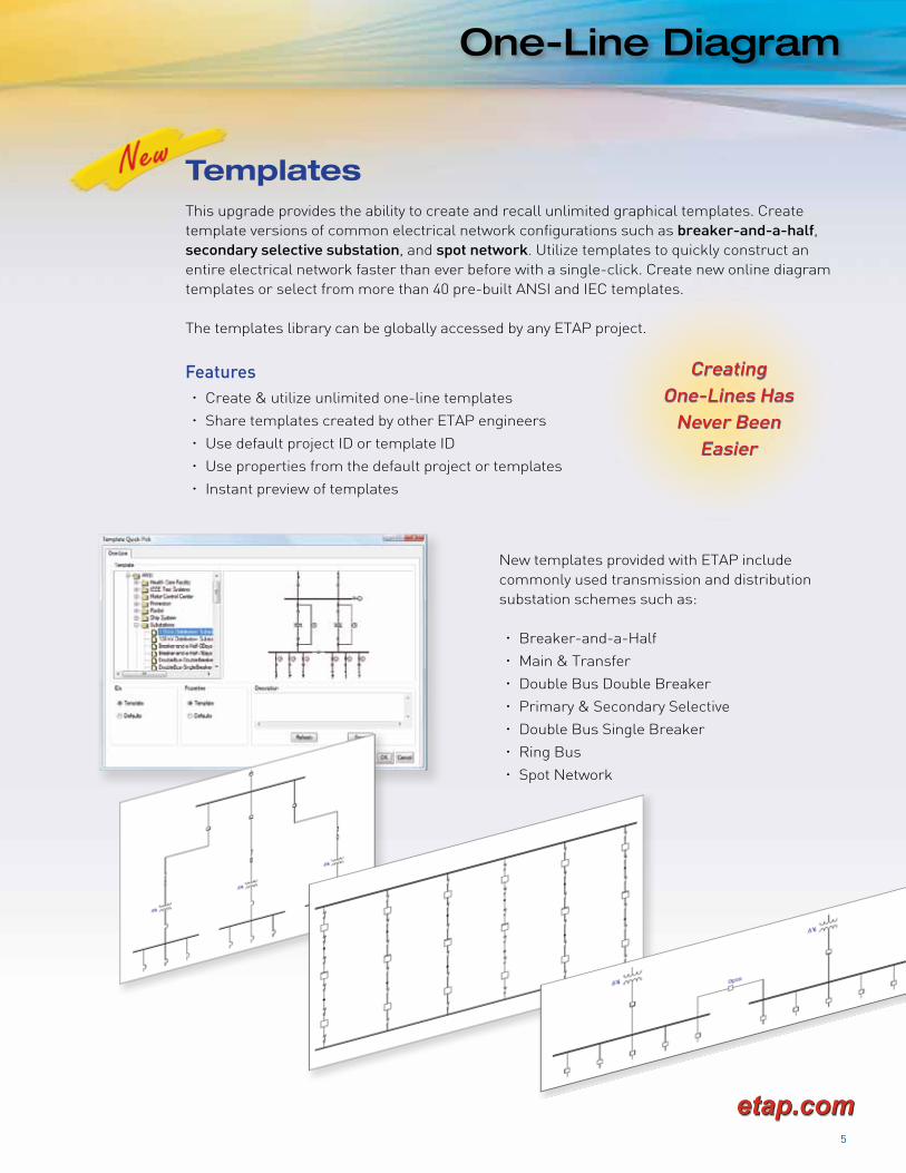
This upgrade provides the ability to create and recall unlimited graphical templates. Create template versions of common electrical network configurations such as breaker-and-a-half, secondary selective substation, and spot network. Utilize templates to quickly construct an entire electrical network faster than ever before with a single-click. Create new online diagram templates or select from more than 40 pre-built ANSI and IEC templates.
The templates library can be globally accessed by any ETAP project.
Features x Create & utilize unlimited one-line templates
x Share templates created by other ETAP engineers
x Use default project ID or template ID
x Use properties from the default project or templates
x Instant preview of templates
New templates provided with ETAP include commonly used transmission and distribution substation schemes such as:
x Breaker-and-a-Half
x Main & Transfer
x Double Bus Double Breaker
x Primary & Secondary Selective
x Double Bus Single Breaker
x Ring Bus
x Spot Network
One-Line Diagram
Templates

Keyboard Shortcuts
ETAP 7.0 includes a large array of keyboard shortcuts, which saves time and effort in creating and editing. Listed below are the most commonly used shortcuts:
Keyboard Shortcuts
Save Timewith
ETAPShortcuts
FilesNew Project ..................................^NOpen Project ................................. ^OSave ................................................^SSave As ....................................... ^ñSPrint Preview ............................. ^ñPPrint ................................................^PClose Project ................................ ^Q
ModeEdit Mode .......................................^EStudy Mode ...................................^M
Shortcut Key Symbols Legendñ ..........................................Shift Key^ ......................................Control Key
EditGraphical Undo .............................^ZGraphical Redo ..............................^YCopy ............................................... ^CCut ..................................................^XPaste ..............................................^VDelete (Dumpster) .................DeletePermanently Delete ............ñDeleteView
Find Tool ........................................^F Increase Symbol Size .....................+Decrease Symbol Size .................... -Fit in Window ................................ ^ØOptions/Preferences ................... ^KSwitch Windows ..........................^F6Previous Window ..................... ^ñF6Close Window ..............................^F4Pan .......................Space Bar + Drag
ZoomZoom In ..........................................^+Zoom Out ....................................... ^-Zoom In Center ...............^Scroll UpZoom Out Center ......^Scroll Down
Working with ElementsRotate 90° CW .............................. ^RRotate 90° CCW ..........................ñRMove in Large IncrementsLeft .................................................�Right ...............................................�Up .....................................................�Down ................................................�Move in Small IncrementsLeft ............................................... ^�Right ............................................. ^�Up ................................................... ^�Down .............................................. ^�Copy to Another Window .... ^ñDrag
DumpsterOpen .............................................. ^DRestore........................................^ñV
SelectSelect All ........................................^ADeselect All ............................... ^ñAGroup............................................. ^GUngroup ........................................ ^UAuto-Select .........................Alt+Click
6

7
etap.cometap.com
Symbol Library
Substitute default one-line diagram symbols with an alternative symbol set for individual device types. Need a SCADA look for your circuit breakers? Launch the symbol substitution tool and swap symbol sets with the press of a button. Symbol substitution allows you to store and recall the default symbols at any point in time.
Symbol Library

ETAP 7.0 brings you new and enhanced capabilities which allow for faster and easier performance of arc flash hazard analysis. Identify and analyze high risk arc flash areas in your electrical system with greater flexibility by simulating various incident energy mitigation methods.
Arc Flash is a completely integrated module that solves multiple scenarios to determine worst case incident energy levels and it also produces professional reports and high quality arc flash labels at a press of a button.
Features x Three-phase & single-phase systems
x Cubic box & open air calculations
x Integrated with ANSI & IEC Short Circuit
x Integrated with Star device coordination
Capabilities x Automatic consideration of generator AC decay &
decrement curve
x AC motor short circuit current decay handling
x Time varying fault clearing time calculation short circuit current decay
x Arc flash calculations for 3-phase & 1-phase panel / UPS systems
x Radial & multiple source system handling
x Extended search beyond the point of multiple upstream source
x Automatic or user-defined source protective device search algorithm option
x Modeling of differential relays, maintenance mode switches, & arc flash photo-sensors
x Zone Selective Interlock Protection (ZSIP) representation
x Generate IEEE 1584 & NFPA 70E look-up table results for different working distances & generate simple summary reports to communicate the results to personnel
x Alerts for PPE ATPV rating violations (maximum allowable PPE arc rating alerts)
x Comprehensive library of protective devices
Arc Flash Analysis
Most Capable & User-FriendlyArc Flash Hazard Assessment Solution
Arc Flash Analysis
8

9
etap.cometap.com
Arc Flash Analysis
In addition to 3-phase systems, ETAP 7.0 allows you to perform arc flash calculations for 1-phase panel / UPS systems.
ETAP gives the option of user-defined categories or to use categories defined by NFPA 70E-2000, 2004, or 2009 standard.
Reduce Risk Improve Safety Enforce Compliance
NFPA 2009 Standard
Single-Phase Arc Flash Calculations
Complies with Standards . . .
x IEEE 1584a 2004
x IEEE 1584 2002
x NEC 110.6
x NESC
x NFPA 70E 2009
x CSA Z462 2008
x OSHA 29 CFR 1910
x ASTM D 120-02a
Compliance with Latest Standards & Calculation Methods

The Arc Flash Result Analyzer is a time-saving tool that allows you to compare and analyze different reports coming from different projects, within the same directory, in a single display. You can compare the results of general information about the project or more specific information such as the results contained from buses, protective devices, or load terminals in an arc flash study.
Features x Sort results from different studies by multiple criteria
x Find the worst-case incident energy results
x Quickly isolate & identify arc flash mis-coordination
x Find which protective devices failed to operate
x Filter out & analyze only the higher hazard category results
x Filter out all equipment with % Ia variation problems
x Locate slow responding protective devices
x Export customized arc flash results to Excel reports
x Analyze the results in Metric or English units
x Color code & filter results by category
Arc Flash Analysis
Understand &Evaluate Results of
Multiple Studiesin One Glance
Arc Flash Result Analyzer
10

11
etap.cometap.com
Generate Energized Electrical Work Permits in Compliance
with Plant Safety Program
Arc Flash Analysis
Work Permits
Data Sheets
Calculate Arc Flash Energy & Generate Labels for 3-Phase & 1-Phase Panel / UPS Systems
Generate & Print LabelsETAP has a wide variety of professional quality arc flash labels in multiple languages including English, Spanish, French, and Portuguese. Automatically batch print arc flash labels based on highest incident energy from all operating modes.
According to NFPA 70E guidelines, permits are required when performing work on energized equipment. Work permits include shock hazard and arc flash analysis results. The work permit needs to be generated for individual bus arc flash results in addition to other pertinent information.
The data sheet is an enhanced version of the arc flash analysis report. It gives a detailed description of what selections were made in the short circuit study case and how the bus results were obtained.
Data sheets can be customized to communicate arc flash study parameters.
x Customize to fit the requirements of each project
x Customizable energized electrical work permits
x Find the safest mode of operation for maintenance work

Speed up data entry for your arc flash projects by globally applying arc flash analysis data based on equipment type and voltage rating.
x Global definition of arc flash analysis data eliminates the need to specify this information in each bus
x Global definition of working distance, bus gaps, approach boundaries, & voltage-rated glove classes
x Specify Arc Flash Analysis Data based on IEEE 1584 2002 or user-defined values
x Globally select Shock Hazard Analysis Data based on NFPA 70E 2004, 2009 or user-defined settings
x Globally change the class settings given by ASTM D 120-02a Standard for voltage-rated protective gloves
x Updates can be made globally without having to modify each bus editor individually
Arc Flash Analysis
Global Data Entry for Equipment
Motor Contributions & Low Voltage Equipment Handling
12
Global Data Based onIndustry Standards orUser-Defined Values
ETAP makes it easier to specify considerations that should be applied to low voltage equipment such as motors and transformers based on NFPA 70E 2009 & IEEE 1584.
x Consider motor fault current decay during the arc flash calculation
x Automatically exclude small motor contributions entirely from the simulation
x Automatically identify & exclude transformers with relatively low voltage & kVA
x Assign a hazard category to these types of equipments automatically based on fault current ranges

13
etap.cometap.com
Short Circuit Analysis
The ETAP Short Circuit module has enhanced duty calculations for generator circuit breakers per the latest version of IEEE Standard C37.013, “IEEE Standard for AC High-Voltage Generator Circuit Breakers Rated on a Symmetrical Current Basis”. The generators are modeled by the sub-transient dynamic model to represent AC and DC decay of short circuit contributions from the generator. It calculates both system-source and generator-source short circuit currents and considers no-load, lagging PF load, and leading PF load for pre-fault conditions.
Features x Generator sub-transient model to represent AC & DC decays
x Generator-source & system-source short circuit currents with no-load, leading PF, & lagging PF
x Symmetrical, asymmetrical, & peak kA at 1/2 cycle
x Symmetrical, asymmetrical, peak , & DC kA as well as degree of asymmetry at generator CB contact parting time
Generator Circuit Breaker IEEE Standard C37.013
ETAP provides several options for ANSI multiplication factor (MF) for high-voltage circuit breaker and bus momentary duty calculations. The options include MF calculated based on system X/R, fixed values at 1.6/2.6, or use of 1.6/2.6 as minimum values. These options allow the user to obtain accurate results as well as to ensure conservativeness in short circuit calculations.
HVCB & Bus Momentary Duty
Generator CB DutyBased on
Fault Current Decrement

ETAP 7.0 includes an extensive list of enhancements for the ETAP Star module. Using these newuser-oriented capabilities, the process of design and evaluation of protective device coordination is significantly faster and easier. Among them is the Star Sequence-of-Operation with new short circuit fault types: Line-to-Line, Line-to-Line-to-Ground in addition to 3-phase and Line-to-Ground.
Star - Device Coordination
The Most Comprehensive & User-Friendly Protective
Device Coordination & Selectivity Analysis Solution
ETAP Star
Enhancements x Sequence-of-Operation
x Device Settings Report
x Panel System Protective Device
x Relay Current Summation
x Relay Test Interface
14

15
etap.cometap.com
Star - Device Coordination
Star Sequence-of-Operation evaluates, verifies, and confirms the operation and selectivity of the protective devices for various types of faults for any location directly from the one-line diagram and via normalized TCC curve views.
Sequence-of-Operation provides a system wide solution for an accurate and realistic operating time and state of protective devices, such as relay, fuse, circuit breaker, trip devices, contactor, etc. The operation time is calculated for each protective device based on its settings, time current characteristic, and interlocks for a specified fault location and type.
ETAP 7.0 enhances this invaluable tool by including Line-to-Line and Line-to-Line-to-Ground Drag-and-Drop Faults in addition to 3-phase and Line-to-Ground Faults.
Sequence-of-Operation

Star - Device Coordination
Star Device Coordination Report Manager provides comprehensive and customizable device settings reports. The manager allows you to preview and print the protective device settings data using Crystal Reports format or Microsoft® Excel format.
Device Settings Report
ETAP 7.0 provides the capability to plot the time current characteristic curves for the main disconnect circuit breaker and fuse as well as the branch circuit protective device curves.
Panel System Protective Device
16
New ExcelReports
Include PanelProtective Devices
in Star Views

17
etap.cometap.com
Star - Device Coordination
Relay element includes a new feature for summing flows through current transformers that can be utilized in arc flash evaluation and sequence-of-operation analysis.
Similar to the differential relay, the summation function sums up the short circuit contribution vectors through the connected CTs according to the CT’s polarity and the direction of current flow.
In addition to ARTTS-6 relay hardware test set interface, ETAP Star now provides an interface to Megger® MPRT Protective Relay Test System via AVTS software.
Additional Enhancements x Partial differential relay modeling
x Ring bus protection
x Multiple source systems protection
Relay Current Summation
Relay Test Set Interface
New Interfacewith Megger MPRT
Summation of CTsBased on Polarity &
Flow Direction
New ExcelReports

Load Analyzer
18
The Load Analyzer module is designed as a generalized load list to report load schedules for power system components such as switchgear, MCC, transformers, cables, lines, panels, etc. Different reports provide informative data regarding all loads connected downstream to equipment.
Load Analyzer is an invaluable tool during the design / planning phase as well as analyzing existing electrical systems because running system studies like load flow analysis may not be possible due to incomplete one-line diagram or data.
Load Analyzer
Reports include the following user options:
x Base or Revision Data
x Configuration
x Loading Category
x Connected / Operating Loads
x Continuous / Intermittent / Spare Loads
x Continuous / Non-Continuous Loads
x Demand Factors
x Diversity (Deviation) Factors
Load Analyzer Reports
x Bus Feeder Loading
x Bus Loading Summary
x Equipment Loading
x Equipment Load List
x Loading Schedule
x Cable Schedule
x Transformer Schedule

19
etap.cometap.com
Switching Management
Switching Management allows the dispatcher to build a complete switching program using a graphical user interface and execute the switching plan all in one step.
Switching Management
Validate & ExecuteSwitching Plans
in One Step
Switching Sequence BuilderThe switching sequence builder contains a list of switching devices and time of execution for circuit breakers, load disconnects, and ground disconnects. The switching builder allows the operator / engineer to specify interdependencies and also rearrange switching order.
Breaker InterlocksA switching sequence simulation can be conducted in Auto Mode and Step Mode using interlock logic entered in the circuit breaker editor. In each switching step, load flow calculations are executed to verify operating conditions and check interlock logic preconditions as well as post conditions.
Execution & Verification of Switching PlansVerify whether the sequence is compliant with safety switching procedures. Confirmations are required for each step before proceeding in order to avoid inadvertent switching.

Transient Stability
The latest edition of ETAP provides the following new capabilities to transient stability, making it the most powerful transient stability program in the industry hands-down.
Transient Stability
20
Features x State-of-the art Governor-Turbine models used in the majority of large industrial power systems
x Isochronous / Droop switching capability for Gas Governor-Turbine with GE Mark IV, V & VI model (GGOV3)
x Solar Gas Governor-Turbine with DLN combustion system model (SGOV1)
x Westinghouse Gas Governor-Turbine with jump rate limiter model (WGOV1)
x Ability to simulate the new Governor-Turbine dynamics including manufacturer unpublished details
x Governor-Turbine models are fully verified and validated by field measurements / benchmark tests
x Higher order integration solution method for synchronous machine swing equation
x Synchronous machine typical data
New State-of-the-ArtGovernor-Turbine Modules
Fully Verified &Validated by
Field Measurements

21
etap.cometap.com
Harmonics / Libraries
The Newton-Raphson method for initial load flow provides an improved convergence for larger systems with small impedances.
Harmonic Analysis
LibrariesETAP 7.0 engineering libraries include many new devices based on user feedback and popularity. ETAP libraries provide complete verified and validated data based on equipment manufacturer’s published data.
Enhanced Libraries
x Solid State Trip Devices
x Cable
x Transmission Line
x Relay
x Battery

Data Exchange
22
ETAP Data Exchange (DataX) is used to import, export, and synchronize data between external data sources and ETAP. DataX provides many utilities including:
x Legacy data transformation into ETAP
x Interface with external architecture databases
x Customizable data mapping
x Intelligent error checking
x Automatic one-line diagram generation
DataX includes several new conversion programs that allow for conversion of third party electrical power system databases to ETAP. The conversion program will automatically generate a multi-layered graphical one-line diagram. A list of available conversion programs are available upon request.
x Import from an Excel spreadsheet with any input data, layout, format, & field names
- Sync Motor
- Induction Motor
- Lumped Load
- Static Load
- 2-Winding Transformer
- Cable
- Bus
x Intelligent equipment mapping
- Recognize the type of equipment up front
- Map equipment as new or existing
x Customizable equipment mapping
- Change the default mapping for equipment already mapped
- Skip importing selective equipment in the user-interface
x Customizable data mapping
- Change the equipment data mapping in the mapping table
x Customizable logic for data dictionary
- Recognize input data based on the default logic provided in XML file
- Add customized logic to the default logic in the XML file for more import flexibility
x Add customized captions & headers to the spreadsheet
DXF
Metafile
XML
IEEE Format
RAW Format
MS Access
MS Excel
e-DPP
SmartPlant Electrical
Third Party Programs
DataX
Open-Format Excel DataX

23
etap.cometap.com
The ETAP-SPEL Data Exchange Interface provides data synchronization between ETAP and Intergraph’s SmartPlant Electrical (SPEL). This bidirectional interface allows joint users to utilize ETAP for design, analysis and automation, and then integrate that data into SPEL to increase electrical efficiency for the construction, operation, and maintenance for the life cycle of the plant.
x Import data from a SPEL-published XML file
x Export data into an XML file for importing into SPEL
x Import cable library data from a SPEL-exported Microsoft database
x Export cable library data to a Microsoft database for importing into SPEL
x Data mapping between SPEL equipment and ETAP elements
x Synchronization of the ETAP cable library with the SPEL cable reference
The SPEL XML file contains the electrical data for equipment and connectivity information in the SPEL project. The ETAP data exchange interface uses information available in SPEL to add, modify, and delete elements. The interface not only auto creates one-line diagrams, it also facilitates multiple data transfers (synchronization) between ETAP and SPEL. As a result, data in ETAP and SPEL are kept consistent without going through the time-consuming manual process of recording additions and modifications in both systems.
The ETAP-SPEL cable library data synchronization is bridged by a Microsoft Access database. Users can import or export ETAP project cable library data into or from the Microsoft Access database using the ETAP Lib Utility. Through the SPEL Lib Utility, users can also export or import cable library data into or from the Microsoft Access database.
SmartPlant® Electrical Interface
SmartPlant Electrical Interface
Bidirectional DataSynchronization

Real-Time Server
24
Server RedundancySystem availability is crucial to the reliable operation of a power management system. In addition to hardware redundancy and failsafe software features, ETAP Real-Time offers redundant client-server setup. Two levels of system redundancy are offered:
x Centralized Redundancy
x Distributed Redundancy
Initialization & Setup Configuration WizardsThe system Initialization Wizard is intended to simplify the steps for connecting the consoles to the real-time system. User-friendly status and progress indication are added for operator convenience and simplicity. The Setup Configuration Wizard is a powerful tool that allows the system integrator administrator to configure the system for commissioning maintenance.
Composite TagsComposite tags provide the system integrator with the ability to write simple and complex mathematical expressions. Commonly used functions are provided as part of the expression builder function library.
Server Status / Health MonitorServer Monitor is a tool that monitors the health, availability, and hierarchy of ETAP Real-Time Servers in a communication complex. Continuous logging provides historical record of server status changes.
ETAP Real-Time is a true client-server configuration designed for Microsoft Windows platforms. The ETAP Real-Time server is the central processing unit that manages the communication between the system, consoles, and controllers.
Real-Time Server
Reliable SystemOperation

25
etap.cometap.com
Advanced Monitoring
Trend ViewsTrending is a user-friendly and flexible application that supports unlimited real-time as well as archived data trending.
State Estimation ComparatorRaw Data Checking (RDC) algorithms have been enhanced for improved error checking in the system model and issues with metering devices such as incorrect polarity, units, etc.
Display OptionsReal-time data display options have been enhanced to show ground switch status as well as individually show / hide the units / values for real-time measurements.
Operator Launch PadOperator Launch Pad provides quick access to all essential views such as annunciation, automatic generation control, energy accounting, etc. from one convenient location on any console.
Ground Switch ElementGround switch is a new element that provides a visual status of the grounding condition on the one-line diagram.
Theme ManagerTheme Manager has been enhanced to include color coding based on area classification on the one-line diagram.
Represent Composite Networks Using ImagesComposite networks can be represented with graphic files (EMF, WMF) in order to easily identify the location or function of the sub-network.
Region Classification & Graphical Assignment of Area, Zone, & RegionAssign region classification for buses in addition to area and zones. ETAP propagates the appropriate area, zone, and region information to all connected equipment. Graphically assign area, zone, and / or region classification using the one-line diagram.
Provides intuitive and integrated real-time monitoring via an intelligent graphical user interface. Monitoring functions include checking the condition of the network, estimating missing system states, detecting network abnormalities, and annunciating alarms based on operating conditions and status changes.
Advanced Monitoring

Real-Time Simulation
26
Event Based Auto-RunIn simulation mode Load Flow Auto-Run is triggered whenever a proposed action is taken on the system (i.e., change in breaker status) providing a step-by-step picture of how the system will react to each change.
Alerts ClassificationFor large systems, a number of critical and marginal alerts may be generated after a real-time simulation study. Filtering based on area, zone and region is included in order for the operator to quickly pinpoint the location of the problem or investigate potential alerts in key locations.
Display OptionsETAP display options allow you to customize the one-line presentation in multiple ways. The most commonly used display options are provided as a quick-pick menu for easy customization of one-line presentations.
A key factor to the successful operation of a power system is the operator’s ability to handle scheduled as well as unforeseen changes in the system condition. With the ETAP Real-Time Simulator, the operator gains knowledge about the electrical system and anticipates the system response before taking an action such as closing / opening a circuit breaker or starting a large motor.
Real-Time Simulation

27
etap.cometap.com
Automatic Generation Control
Load Frequency ControlUtilizes system frequency and interchange flows to determine the dispatch from each of the generating units under load frequency control (LFC).
Economic DispatchEconomic Dispatch allows generation facilities to produce energy at the lowest cost to reliably serve consumers while recognizing any operational limits of generation and transmission facilities.
Interchange Transaction ScheduleInterchange Transaction Scheduling (ITS) provides the capability to schedule energy transfer from one control area to another while considering wheeling, scheduling ancillary services, and financial tracking of energy transactions.
AGC ViewThe AGC view is a user-friendly operator / dispatcher tool for displaying operating values and calculated generator set points.
Generator ControllerManually control generators to start, stop, change set points, as well as switch between various generator operating modes.
The objective of the Automatic Generation Control (AGC) is to maintain the frequency of a Power Distribution System and to keep tie-line power close to the scheduled values. AGC also calculates the required parameters to optimize the operation of the generation units under the AGC action based on economic dispatch and interchange commitments.
Automatic Generation Control
Energy Accounting
28
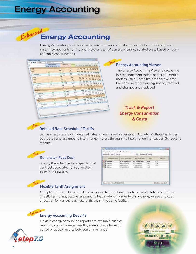
Detailed Rate Schedule / TariffsDefine energy tariffs with detailed rates for each season demand, TOU, etc. Multiple tariffs can be created and assigned to interchange meters through the Interchange Transaction Scheduling module.
Generator Fuel CostSpecify the schedule for a specific fuel contract associated to a generation point in the system.
Flexible Tariff AssignmentMultiple tariffs can be created and assigned to interchange meters to calculate cost for buy or sell. Tariffs may also be assigned to load meters in order to track energy usage and cost allocation for various business units within the same facility.
Energy Accounting ViewerThe Energy Accounting Viewer displays the interchange, generation, and consumption meters listed under their respective area. For each meter the energy usage, demand, and charges are displayed.
Energy Accounting ReportsFlexible energy accounting reports are available such as reporting current viewer results, energy usage for each period or usage reports between a time range.
Energy Accounting provides energy consumption and cost information for individual power system components for the entire system. ETAP can track energy related costs based on user-definable cost functions.
Energy Accounting
Track & ReportEnergy Consumption
& Costs

29
etap.cometap.com
Load Forecasting
Pattern LibraryGraphically define unlimited patterns such as MW and Mvar loading, temperature, and humidity. The Pattern Library is useful for load forecasting in the event sufficient historical data is not available to train the forecast model.
Load Sector LibraryThe Profile Library connects to the Pattern Library and allows the user to select patterns and build a yearly profile. The yearly profile can be compromised of many individual 24-hour pattern shapes for loading, temperature, as well as humidity with special considerations for holidays.
Weekly Forecast & Revised ForecastSelect individual or group of locations for which a forecast is required. ETAP generates a continuous load forecast up to a week ahead. The weekly forecast is revised on an hourly basis based on present operating conditions.
Load Forecasting ViewerDisplays the load forecast up to one week ahead, as well as the revised forecast calculated each hour. The viewer also allows you to superimpose week-ahead forecast and revised forecast with actual demand, thereby giving the system operator / engineer a metric as to the quality of the forecast. Appropriate offsets may be utilized for future forecasts or measures may be taken to improve the accuracy of the forecast.
Short-Term Load Forecasting (STLF) is a tool to reliably and accurately forecast future short term loading in the system. STLF can be used to generate a forecasting model for various loads or interchange lines. STLF is set up to allow the user to train and forecast multi-meters on a continuous basis on hourly increments for a span of one week ahead.
Load Forecasting
Accurate &Reliable
Forecasting
Intelligent Load Shedding
30
Load Shedding Logic EditorThe Load Shedding Logic Editor allows the system integrator to start from ETAP predefined event handling logic and customize it for each individual project. This time based logic can be based on equipment properties and settings, real-time measurements, alarms, and status. Post event logic can also be considered.
Equipment Overload HandlingImplements optimized load shedding techniques to eliminate overloads on equipments such as generators, transformers, lines, etc. It monitors equipment capabilities such as Max MVA, Line Ampacities, etc. and determines the loads to shed to bring the power flows to safe operating conditions. Users can define the maximum duration time of overloads before executing actions.
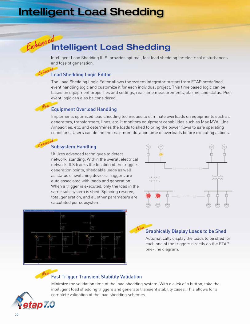
Subsystem HandlingUtilizes advanced techniques to detect network islanding. Within the overall electrical network, ILS tracks the location of the triggers, generation points, sheddable loads as well as status of switching devices. Triggers are auto associated with loads and generation. When a trigger is executed, only the load in the same sub-system is shed. Spinning reserve, total generation, and all other parameters are calculated per subsystem.
Graphically Display Loads to be ShedAutomatically display the loads to be shed for each one of the triggers directly on the ETAP one-line diagram.
Fast Trigger Transient Stability ValidationMinimize the validation time of the load shedding system. With a click of a button, take the intelligent load shedding triggers and generate transient stability cases. This allows for a complete validation of the load shedding schemes.
Intelligent Load SheddingIntelligent Load Shedding (ILS) provides optimal, fast load shedding for electrical disturbances and loss of generation.

31
etap.cometap.com
ETAP 7.0 System Requirements
Operating System (32-bit or 64-bit)
x Microsoft® Windows Vista®
(Home Premium, Business, Enterprise)
x Microsoft® Windows® XP (SP3)
(Professional or Home Edition)
x Microsoft® Server 2008
x Microsoft® Server 2003 R2 (SP2)
x Microsoft® Server 2003 (SP2)
Other Software Requirements x Microsoft® Internet Explorer® 5.01 or
higher (or minimum version level as
specified by the operating system in use)
x Microsoft® .NET Framework v1.1 (SP1)
x Microsoft® .NET Framework v2.0 (SP1)
Hardware Requirements x USB port (for stand-alone license)
x Ethernet port with network access
(for network license)
x DVD drive
x 5 to 80 GB hard disk space (based on
project size, number of buses)
x 19” monitors recommended (dual
monitors highly recommended)
x Minimum display resolution - 1024x768
Recommended Hardware100 Bus Projects:
x Intel® dual/quad core - 2.0 GHz
(or equivalent)
x 2 GB RAM
500 Bus Projects:
x Intel® dual/quad core - 2.0 GHz
(or equivalent)
x 4 GB RAM
1,000 Bus Projects:
x Intel® dual/quad core - 3.0 GHz with
hyper-threading with high speed bus
(or equivalent)
x 8 GB RAM (high speed)
x 64-bit operating system
10,000 Bus Projects and Higher:
x Intel® dual/quad core - 3.0 GHz with
hyper-threading with high speed bus
(or equivalent)
x 12 GB RAM (high speed)
x 64-bit operating system
Keep Up-to-Date with ETAP ProductsImproving and expanding our products is a continual process for the ETAP development team. These ongoing product updates ensure that ETAP continues to not only meet, but exceed our customer requirements.
ETAP Upgrade & User-Support Maintenance Contract (UUC)The ETAP Upgrade and User-Support Contract (UUC) is the most cost-effective way to protect your ETAP investment by providing product upgrades and technical support for your ETAP software. Extending your maintenance support agreement will allow you the opportunity to apply ETAP’s unique features and sophisticated analysis techniques to all your power system analysis projects. With a valid UUC maintenance support agreement, you receive:
x Free version upgrades including automatic shipment of new releases
x Unlimited access to user / technical support
x Latest device libraries updates
x Full access to ETAP User FTP and download sites
x Access to prerelease and beta versions of new products and upgrades
Contact [email protected] or (949) 900-1000 today to receive more information and a quote to receive all these great benefits offered in the ETAP Upgrade and User-Support Contract.
FeedbackOperation Technology, Inc. is dedicated to providing our customers with a superior product experience, and user feedback is one of the central elements of this commitment. In fact, ETAP is designed based on 95% of user suggestions and requests! Tell us how we are doing by:
x Filling out a short survey at etap.com (click on User Feedback Form)
x E-mailing ETAP Technical Support at [email protected]
x Sharing your comments with your local ETAP Authorized Representative
Visit ETAP.comThe ETAP web site is your best resource for up-to-the minute information about ETAP products and services. The site includes the latest product update announcements, a worldwide training calendar, video tutorials, frequently asked questions, archived webinars, ETAP downloads, white papers and articles, information about ETAP User Groups, and much more. Click on the “Request ETAP News” link to receive periodic e-mails informing you of what’s new in ETAP.
© 2009 Operation Technology, Inc. All rights reserved. Certain names and/or logos used in this document may constitute trademarks, service marks, or trade names of Operation Technology, Inc. Other brand and product names are trademarks of their respective holders.
ETAP Support
31
etap.cometap.com

OperatiOn technOlOgy, inc.17 Goodyear, Suite 100 | Irvine, CA 92618
T 800.477.ETAP | T 949.900.1000 | F 949.462.0200
etap.cometap.com