Embed Size (px)
Citation preview
© 2013 ETAP
Electrical Transient Analysis Program
Victor Andrade
Senior Power Engineer
SmartPlant Electrical

© 2013 ETAP
ETAP Overview
• World leader in Electrical Analysis Software
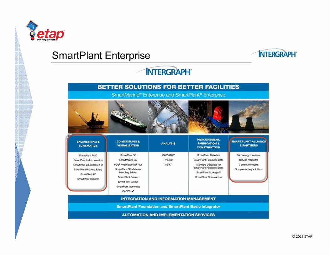
• SmartPlant Alliance & Partner
• Complement SmartPlant
© 2013 ETAP
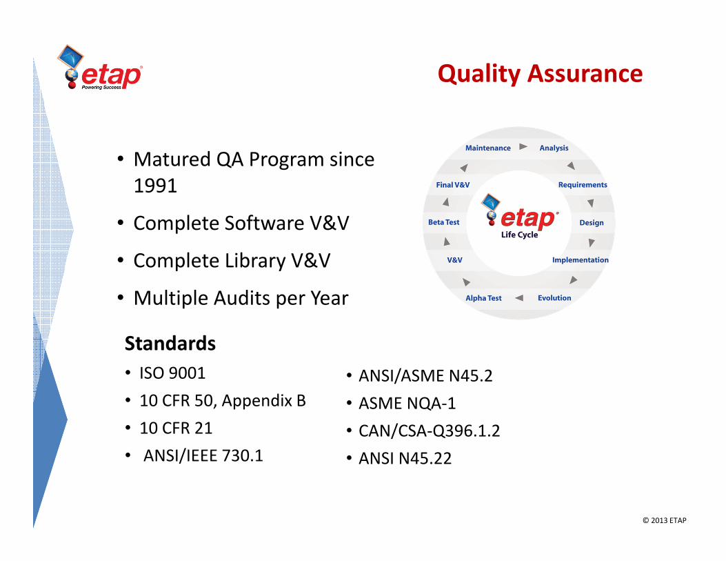
• Matured QA Program since
1991
• Complete Software V&V
• Complete Library V&V
• Multiple Audits per Year
Standards
• ISO 9001
• 10 CFR 50, Appendix B
• 10 CFR 21
• ANSI/IEEE 730.1
• ANSI/ASME N45.2
• ASME NQA-1
• CAN/CSA-Q396.1.2
• ANSI N45.22
Quality Assurance

© 2013 ETAP
Nuclear High Impact Software
• International Nuclear Users
• Brazil, Canada, China, Finland, France, Germany,
India, Japan, South Korea, Spain, USA
• USA Nuclear Generation Plants
• 60 out of 64 Standardized on ETAP (94%)

© 2013 ETAP
• Consulting Firms
• Distribution Systems
• Transmission Systems
• Generation Plants
• Oil & Gas Facilities
• Commercial Buildings
• Hospitals
• Mission Critical Facilities
• Data Centers
• Manufacturing Plants
• Government Facilities
• Metals & Mining Plants
• Transportation Systems
• Universities & Education
5,000 Customers Worldwide

© 2013 ETAP
Consulting FirmsIndustry Standard

© 2013 ETAP
SmartPlant & ETAP
• Validating the Design using SPEL Basic and ETAP
• Making engineering design more efficient
• Bidirectional interface between SmartPlant electrical
and ETAP
• Detailed Electrical design tasks
© 2013 ETAP

© 2013 ETAP
SPEL – ETAP Interface

© 2013 ETAP
Validating the design
• Intelligent solution for making the right decision
• Validate before commissioning a project to eliminate
expensive mistakes
© 2013 ETAP
Terminology
Power Systems Model
A software representation of a one-line diagram, in which all components in
the electrical system – circuit breakers, transformers, capacitors, bus bars,
and conductors, as well as large equipment like generators, motors, and
UPS’s – are depicted as mathematical representations. By running
simulations of the model to test for specific problems, e.g. short circuit
analysis, engineers are able to isolate potential issues in the system, until all
have been effectively removed.
Single Line Diagram (SLD)An electrical schematic in which all electrical elements such as circuit
breakers, transformers, capacitors, bus bars, conductors, etc. are shown by
standardized schematic symbols. Instead of representing each of three
phases with a separate line, only one conductor is represented to depict all
three phases. Also called a “one-line” for short.

© 2013 ETAP
Software Version
SmartPlant 2009 (SP 5 HF13) ETAP 12.5
© 2013 ETAP
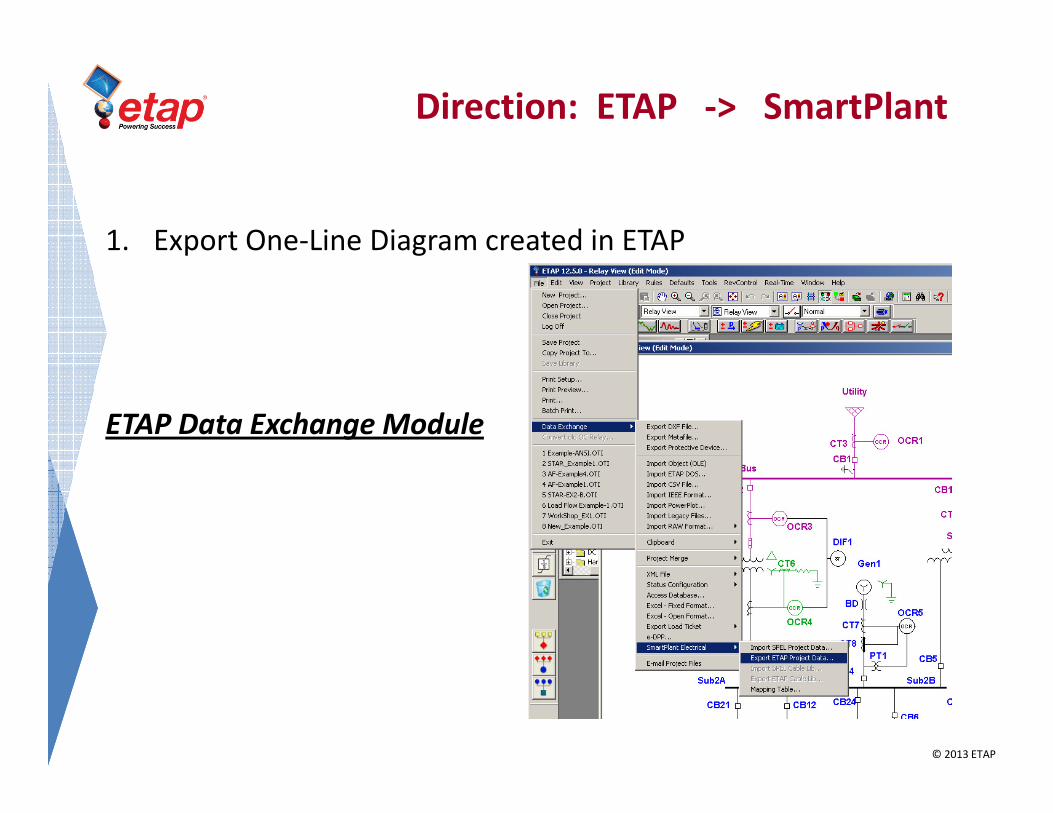
Direction: ETAP -> SmartPlant
1. Export One-Line Diagram created in ETAP
ETAP Data Exchange Module
© 2013 ETAP
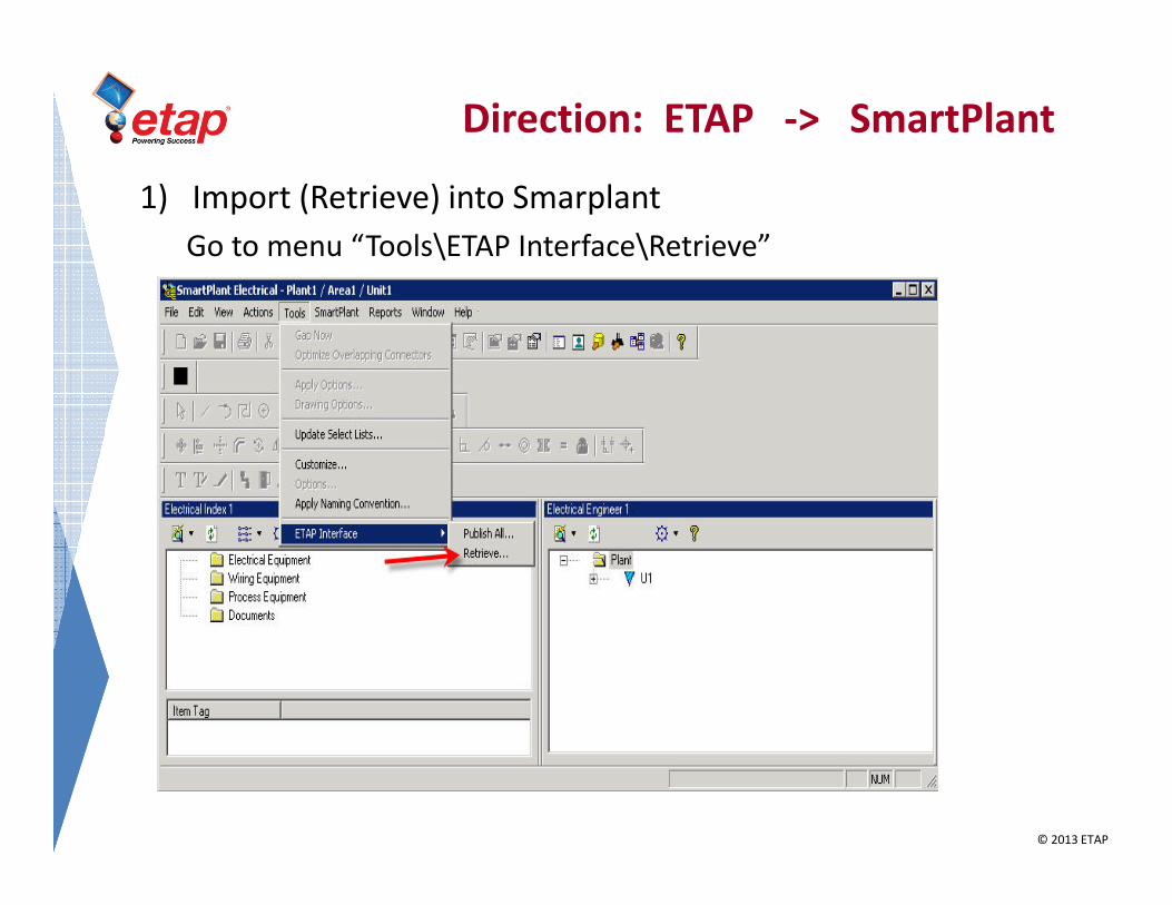
Direction: ETAP -> SmartPlant
1) Import (Retrieve) into Smarplant
Go to menu “Tools\ETAP Interface\Retrieve”

© 2013 ETAP
Direction: ETAP -> SmartPlant
2) Go to menu “SmartPlant\To Do List”.
© 2013 ETAP
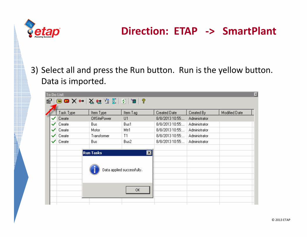
Direction: ETAP -> SmartPlant
3) Select all and press the Run button. Run is the yellow button.
Data is imported.

© 2013 ETAP
Direction: ETAP -> SmartPlant
4) Elements are display in “Electrical Index” and “Electrical
Engineer”.

© 2013 ETAP
Single-Line Diagram
Elements & Database
• Deliver more than just a Single Line Diagram
• Deliver an intelligent and validated Single Line Diagram
© 2013 ETAP
Direction: SmartPlant ���� ETAP
1. System for Design in SmartPlant Electrical
2. Enter Electrical Equipment and Properties into SPEL
3. Generate SLD in SmartPlant Electrical
4. Publish Data into XML
5. Import XML into ETAP for Study Verification

© 2013 ETAP
System for Design in SPEL

© 2013 ETAP
Direction: SmartPlant ���� ETAP
1. System for Design in SmartPlant Electrical
2. Enter Electrical Equipment and Properties into SPEL
3. Generate SLD in SmartPlant Electrical
4. Publish Data into XML
5. Import XML into ETAP for Study Verification
© 2013 ETAP
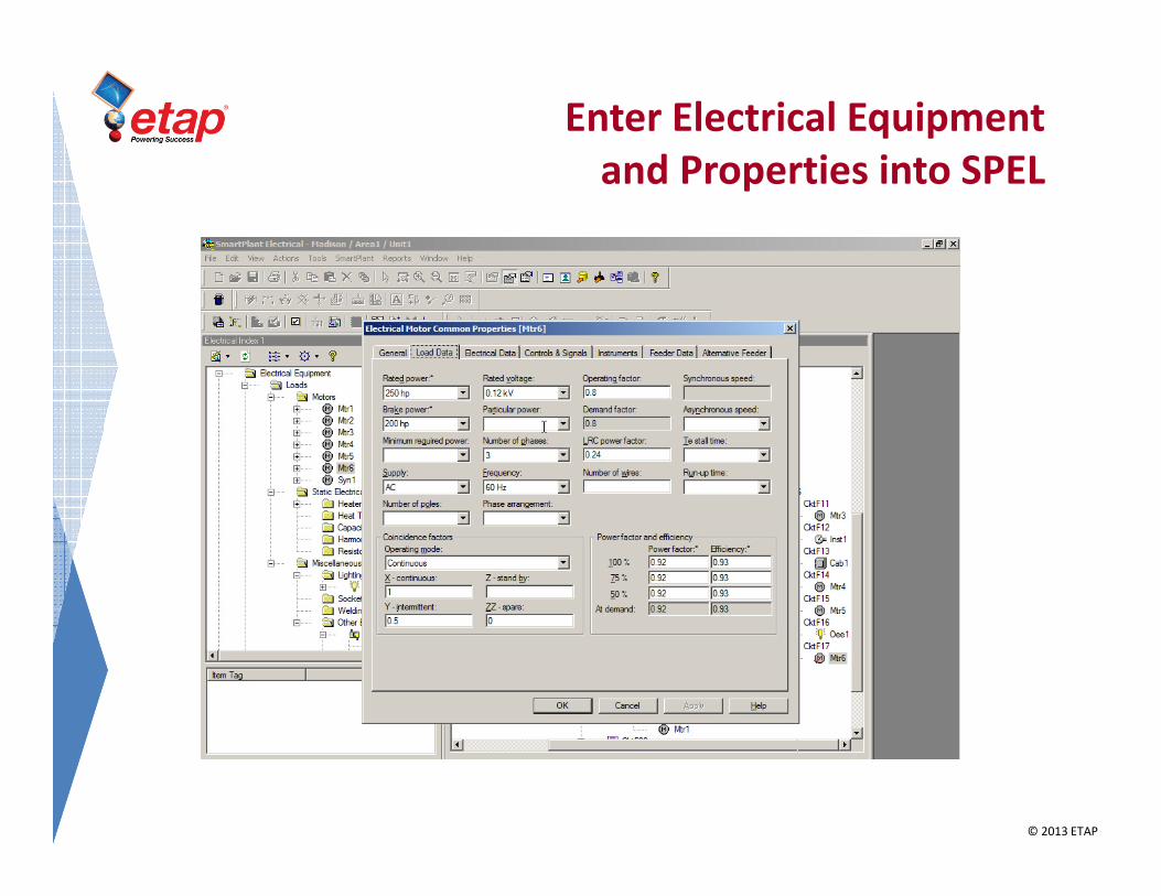
Enter Electrical Equipment
and Properties into SPEL

© 2013 ETAP
Direction: SmartPlant ���� ETAP
1. System for Design in SmartPlant Electrical
2. Enter Electrical Equipment and Properties into SPEL
3. Generate SLD in SmartPlant Electrical
4. Publish Data into XML
5. Import XML into ETAP for Study Verification
© 2013 ETAP
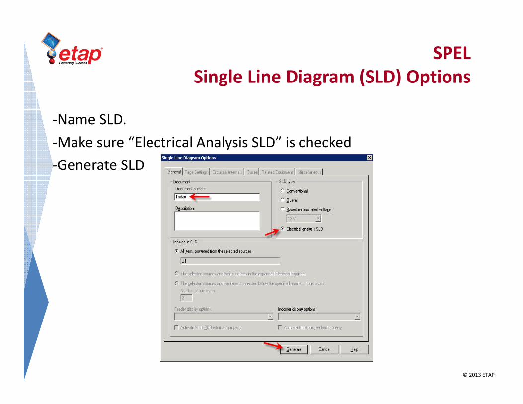
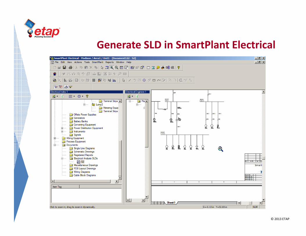
SPEL
Single Line Diagram (SLD) Options
-Name SLD.
-Make sure “Electrical Analysis SLD” is checked
-Generate SLD
© 2013 ETAP
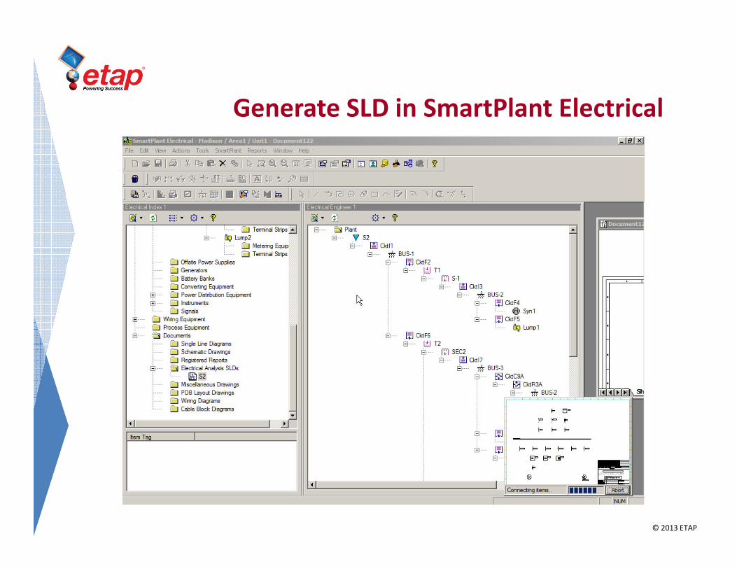
Generate SLD in SmartPlant Electrical
© 2013 ETAP
Generate SLD in SmartPlant Electrical

© 2013 ETAP
Direction: SmartPlant ���� ETAP
1. System for Design in SmartPlant Electrical
2. Enter Electrical Equipment and Properties into SPEL
3. Generate SLD in SmartPlant Electrical
4. Publish Data into XML
5. Import XML into ETAP for Study Verification

© 2013 ETAP
Direction: SmartPlant ���� ETAP
Right click on SLD. Select “Publish to External Analyzing Tool..”
and save XML file

© 2013 ETAP
Direction: SmartPlant ���� ETAP
1. System for Design in SmartPlant Electrical
2. Enter Electrical Equipment and Properties into SPEL
3. Generate SLD in SmartPlant Electrical
4. Publish Data into XML
5. Import XML into ETAP for Study Verification

© 2013 ETAP
Import XML into ETAP for Study Verification
ETAP Data Exchange Module

© 2013 ETAP
SPEL (SLD) and ETAP (Analysis)
1. Import XML generated in SPEL into ETAP
– Advantages:
• No need to recreate the SLD or re-enter data
• Electrical properties for components is imported
• Perform Analysis (Calculations) such as :
– Load Flow
– Voltage Drop
– Short Circuit
© 2013 ETAP
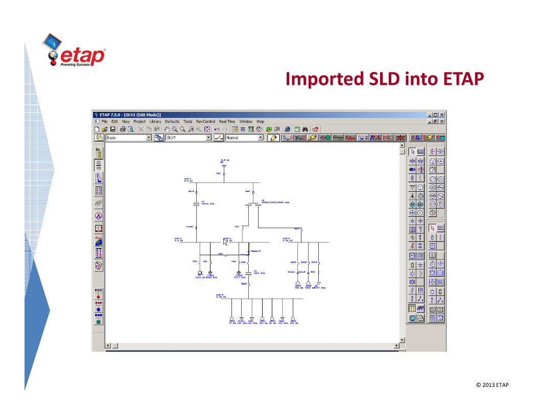
Imported SLD into ETAP

© 2013 ETAP
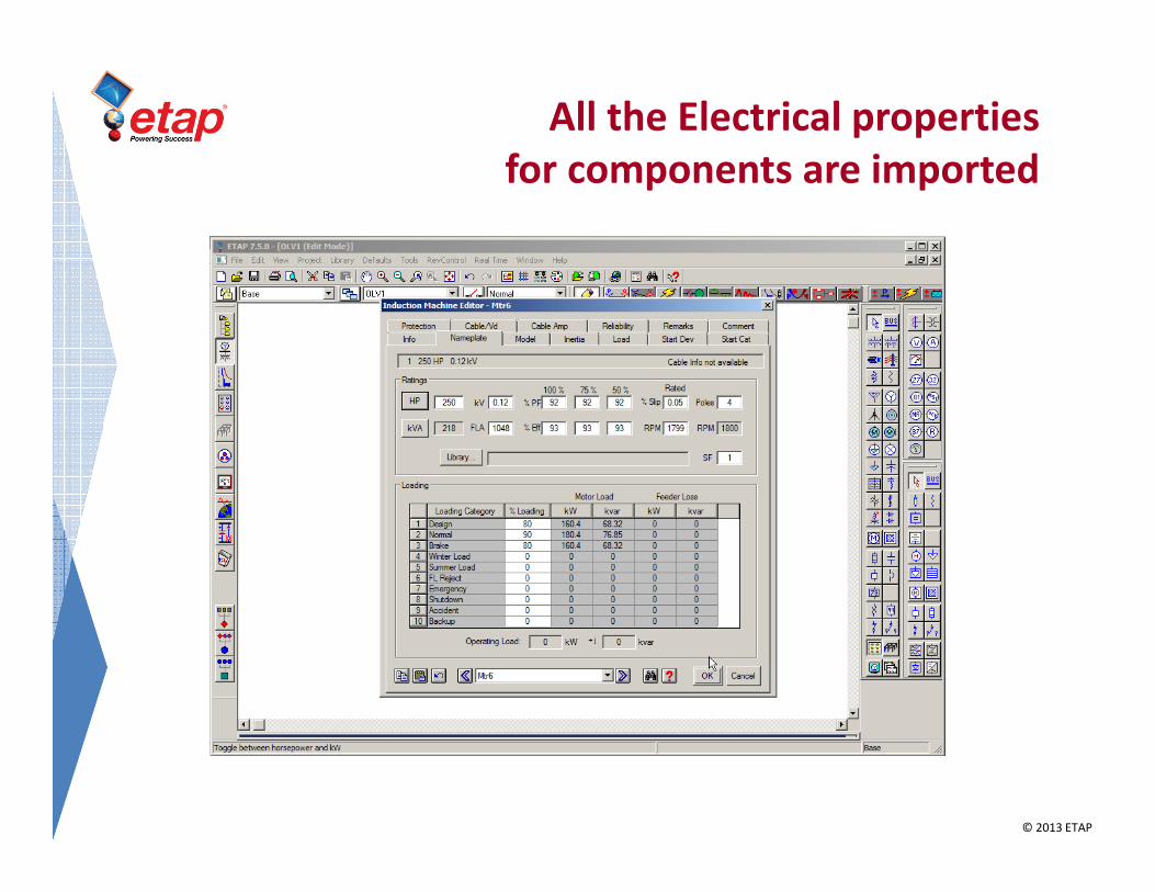
SPEL (SLD) and ETAP (Analysis)
1. Import XML generated in SPEL into ETAP
– Advantages:
• No need to recreate the SLD or re-enter data
• Electrical properties for components is imported
• Perform Analysis (Calculations) such as :
– Load Flow
– Voltage Drop
– Short Circuit
© 2013 ETAP
All the Electrical properties
for components are imported

© 2013 ETAP
Capability of Performing Analysis
ETAP’s Analysis Modules
© 2013 ETAP
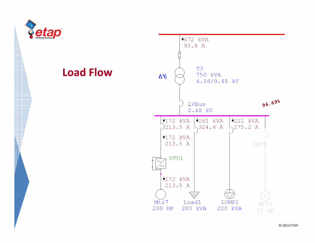
Load Flow
© 2013 ETAP
Terminology
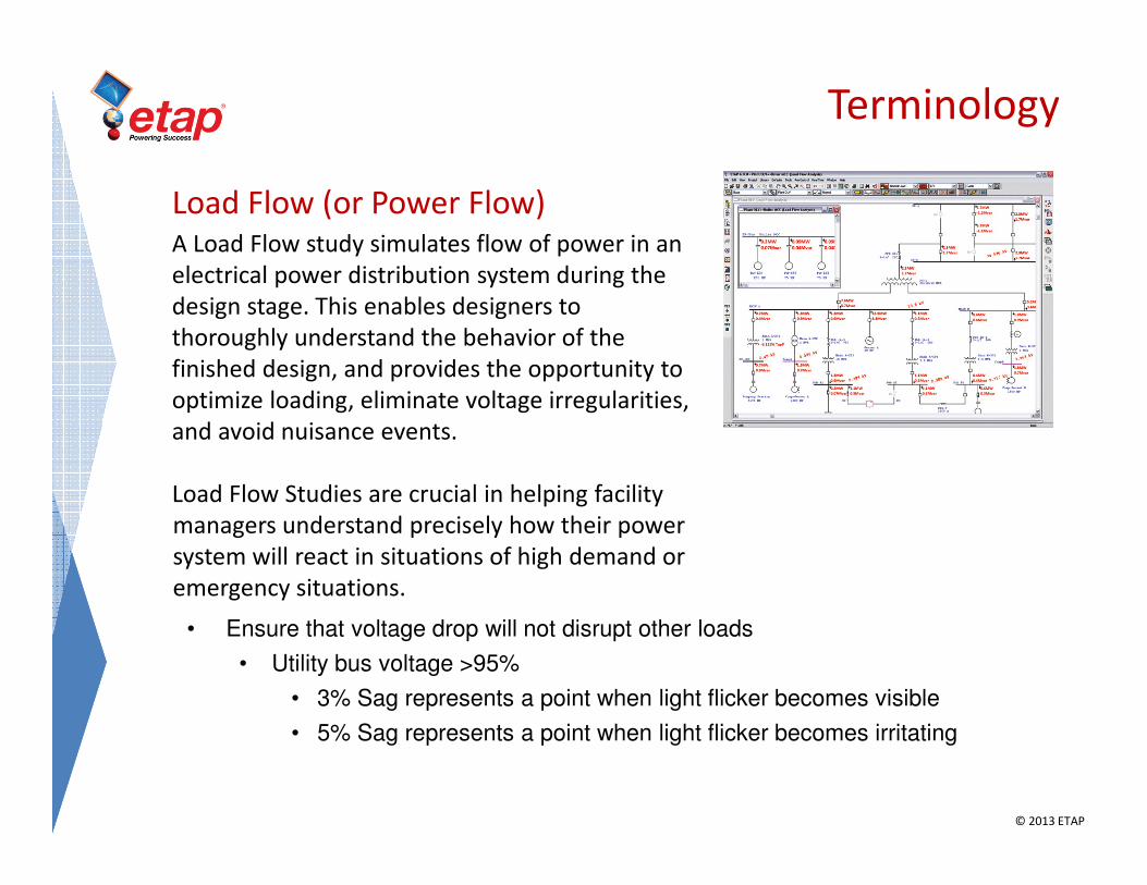
Load Flow (or Power Flow)A Load Flow study simulates flow of power in an
electrical power distribution system during the
design stage. This enables designers to
thoroughly understand the behavior of the
finished design, and provides the opportunity to
optimize loading, eliminate voltage irregularities,
and avoid nuisance events.
Load Flow Studies are crucial in helping facility
managers understand precisely how their power
system will react in situations of high demand or
emergency situations.
• Ensure that voltage drop will not disrupt other loads
• Utility bus voltage >95%
• 3% Sag represents a point when light flicker becomes visible
• 5% Sag represents a point when light flicker becomes irritating

© 2013 ETAP
If the Auto Display
feature is active, the
Alert View Window will
appear as soon as the
Load Flow calculation
has finished.
© 1996-2009 Operation Technology, Inc. – Workshop Notes: Load Flow Analysis Slide 38

© 2013 ETAP
SPEL – ETAP bidirectional interface
© 2013 ETAP
Terminology
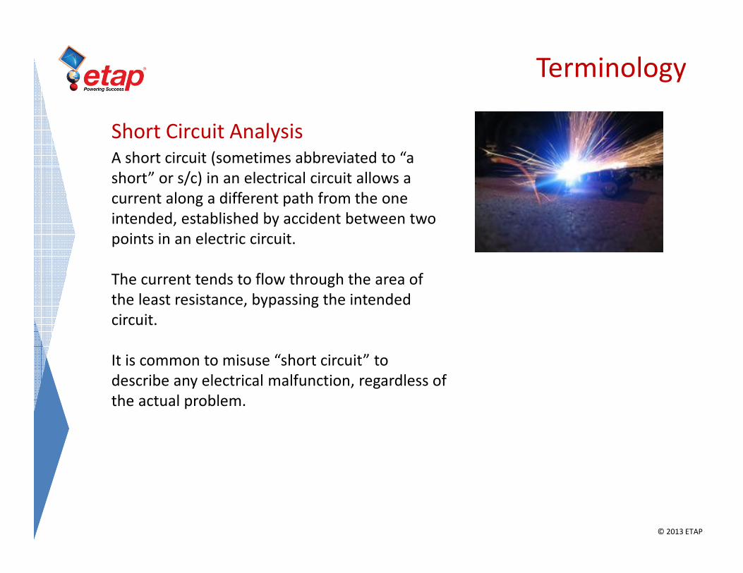
Short Circuit AnalysisA short circuit (sometimes abbreviated to “a
short” or s/c) in an electrical circuit allows a
current along a different path from the one
intended, established by accident between two
points in an electric circuit.
The current tends to flow through the area of
the least resistance, bypassing the intended
circuit.
It is common to misuse “short circuit” to
describe any electrical malfunction, regardless of
the actual problem.

© 2013 ETAP
Run a 3-phase Duty SC calculation for a
fault on Bus4. The display shows the
Initial Symmetrical Short-Circuit Current.
3-Phase Duty SC Results
© 2011 Operation Technology, Inc. PROPRIETARY & CONFIDENTIAL Slide 41

© 2013 ETAP
Supported elements between ETAP and SPEL

© 2013 ETAP
Supported elements between ETAP and SPEL

© 2013 ETAP
Mapping Element Properties
© 2013 ETAP
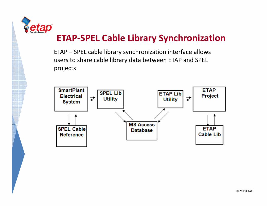
ETAP-SPEL Cable Library Synchronization
ETAP – SPEL cable library synchronization interface allows
users to share cable library data between ETAP and SPEL
projects