Embed Size (px)
Citation preview

Ethernet as a Channel for Protective Relaying
by John Benckenstein

14 Years ago I presented: “System Reliability Improvements
through use of Fiber Optics”
• I predicted multiplexed communications would take the lead over:– Pilot Wire– Direct Fiber– Audio Tones– Power-Line Carrier
• I was right!• Single fiber solution still viable• Multiplexed channels with self-healing routes are preferred• “Nothing will ever come along to replace this”.
Something New is Here Now
• I was wrong, this new Ethernet is worth a good look• It is ready today to handle all of your substation
communications requirements, including Protective Relaying• How did this happen?
– Bandwidth Requirements have Grown by an Order of Magnitude– Pursuit of the Mythical Smart Grid– Up to you Relay Engineers how fast this technology is adopted
• Most of us here are “Techies” to a degree– At office we are conservative and resist change– At home, we jump on any new technology

Ethernet is High Tech “Under the Covers”
• It has the features you want, without the complexity• Over the past 35 years a lot of really smart people took their time to
create this new Ethernet just for you.• Don’t let the acronyms scare you - RMON, SNMP, Telnet, VLANs (Port-based
and Tag-based), GVRP, Port-mirroring, CLI, Port Security, SNTP, BootP, DHCP, IGMP Snooping, 802.1p, or QoS,
• Remember STP, VLAN, QoS– Spanning Tree Protocol– Virtual Local Network– Quality of Service
• Your Smart Grid needs more bandwidth• Can Ethernet provide you with the same level of comfort,
flexibility, capacity and performance as SONET?

Ethernet Timeline and Future
• Communications Infrastructure changes every 5 to 10 years in IT departments.
• As these systems are being replaced today, they are finding less SONET and more Ethernet systems to choose from.
• Your relays last 15 to 20 years.

What is a Relay Engineer to Do?
• Fortunately there are a few companies specializing in relay communications using packet technology.
• Your traditional channel types can be interfaced with new packet over Ethernet multiplexers.– Audio tone– ANSI C37.94– RS422, G703.2– Direct Contacts– RS232 (Mirrored bits)– HCB-1 pilot wire
• These broadband multiplexers meet IEEE1613

Basics of Ethernet
• To transfer ANY type of channel over a digital medium (like TDM or Ethernet) the data must be sampled at precise 125 uSec intervals producing a series of 8-bit bytes representing those sample points.
• The difference with Ethernet starts AFTER the byte is created.• In TDM this byte becomes a DS0 channel, which may be 1 of
24 in a T1 system, or 1 of 2016 in an OC-3 system.• In a packet system this byte is put into a packet with
selectable bandwidth through the Ethernet. (Can put several bytes into one packet.)

Layer 2 Packet (Frame) Format
Payload is 46 to 1500 bytes
This part is used by the multiplexer
Determines protocol used in payload
VLAN/QoS (optional)
CRC/Frame Check Sequence
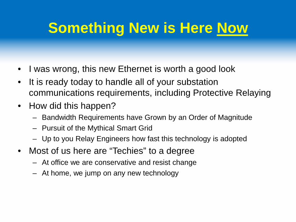
Typical Layer 2/3 Switch
Eight 10/100 portsMix of Optic and Electrical
Two SFP Optical GigE ports
GigE SFP (Small Form-factor Pluggable)

Mapping Channels in TDM
TO 383
TO 007
1-1 2-1 1-1 2-1 1-1 2-1 1-1 2-1EAST NORTH EAST NORTH EAST NORTH EAST NORTH
1 ---PLOW--- ---PLOW--- ---PLOW--- ---PLOW--- ---PLOW--- ---PLOW--- ---PLOW--- ---PLOW---2 PRI(1a)--- ------------ ------------ ---PRI(3a) PRI(1a)--- ---PRI(1a)3 PRI(3a)--- ---PRI(3a) PRI(5a)--- ---PRI(5a)45 ---232(5a) 232(3a)---6 232(5b)--- ---232(7a) 232(7a)--- ---232(3b)7 232(8a)--- ---232(8a)8 232(8b)--- ---232(4b)9 232(8a)- --------------- ---------------- ---------------- ---------------- -232(8b)101112131415..24/30
(M) (B)
SUB 2
Timeslots
SUB 1007 1006
SUB 3836 383
SUB 4

Mapping Channels in Ethernet
GBE
GBE
GBE Ethernet Switch
2
Ethernet Switch 3
Ethernet Switch1
Ethernet Switch4
“Connect 232 from slot 2 in chassis 1 to 232 in slot 2 in chassis 4,”

Mapping in TDM vs. Packets
TDM Mapping• Hardware
– System Control Module– Framers– Time Slot Aligners– DACS– Optic al Drivers
• Software– Learn physical network configuration– Map Origin Timeslot to port– Map Destination Time slot to Port– Map all pass-through time slots– Apply channel application settings
Packet Connection• Hardware
• System Control Module• DACS• Switch
• Software• Connect source to
Destination• Set control settings per
channel• Apply channel
application settings

Mapping Channels in Ethernet
GBE
GBE
GBE Ethernet Switch
2
Ethernet Switch 3
Ethernet Switch1
Ethernet Switch4
“Connect 232 from slot 2 in chassis 1 to 232 in slot 2 in chassis 4,”

Administrative Settings
• Password control• Network Aware• Channel-specific application settings• SOE: Sequence of Events, Alarm Status• Ethernet and TDM performance monitor• Network and TDM Clock sources
– IRIG or NTP for real-time clock, BITS for network
• Settings that control how data is passed through network– Source and Destination Mapping (TDM and Packet)– VLAN: Virtual Local Are Network– QoS: Quality of Service– Bandwidth Economy– Jitter Buffer

Effect of Jitter on Received Data
local
remote
Constant Sample clock
Local error
Remote data has jitter

How Context is Inserted into Frame
Context
…1
332 --
3 21
30 57
“Real time Protocol”
…1
332
463
21 CRC
Ethernet
Channel card cage
Packet Formatter and CRC generator
data
DEST SRC ID QOS
DACSContext
• Samples per packet• Chassis slot position• QoS• VLAN• Jitter Buffer
Context is set up via Admin Channel
Context is then part of data packet

Proper Clock Recover with Zero Jitter
local
localerror
Constant Sample clock

Three Hurdles to Accept Ethernet as a Channel for Protective Relaying
• Is there a Redundant Path Option when my Primary Fiber Path is Broken?
• Is my Channel Latency Deterministic and Low Enough?
• Do I have sufficient Bandwidth? How Scalable is my
System?

One of Three Hurdles to Accept Ethernet as a Channel for Protective Relaying
• Is there a Redundant Path Option when my Primary Fiber path is Broken?– TDM System have various types of self-healing rings
• APM, ILS, Mini-DACS, FFHS, Path Switched, Line Switched, BLSR, UPSR, etc.• All effectively remap the broken channels the opposite direction around the ring.• May require some manual preconfiguring to obtain fastest switching times• Expect 25 to 150 mS recovery times
– Packet over Ethernet uses variations of STP (Spanning Tree Protocol)

Spanning Tree Protocol, in a Ring
Ethernet Switch ID = 85
Ethernet Switch ID = 31
Ethernet Switch ID = 12
Ethernet Switch ID = 20
Ethernet Switch ID = 16
Ethernet Switch ID = 42Relay-A
Relay-B
Relay-B
Relay-A
Relay-C
Relay-C
Relay-E
Relay-E
Relay-D
Relay-D
• Before Break, SW 12 is root• SW 85 port to 42 is discarding (blocked)• Relays A &E connected long way
Discarding

Spanning Tree Protocol, in a Ring
Ethernet Switch ID = 85
Ethernet Switch ID = 31
Ethernet Switch ID = 12
Ethernet Switch ID = 20
Ethernet Switch ID = 16
Ethernet Switch ID = 42Relay-A
Relay-B
Relay-B
Relay-A
Relay-C
Relay-C
Relay-E
Relay-E
Relay-D
Relay-D
• Before Break, SW 12 is root• SW 85 port to 42 is discarding (blocked)• Relays A &E connected long way
• After Break, SW 85 is root• SW 12 port to 31 is discarding (blocked)• Relays C connected long way• Relays B & D are unaffected
Discarding After Break

One of Three Hurdles to Accept Ethernet as a Channel for Protective Relaying
• What is the recovery speed when my primary fiber path is broken?– TDM: Expect 25 to 150 mS recovery times
– Packet over Ethernet: Expect 25 to 50 mS recovery times• With MSTP, Packet networks offer something not available in TDM. Near zero-delay
switching.
• Redundancy in Packet Network is equivalent to or better than TDM

Two of Three Hurdles to Accept Ethernet as a Channel for Protective Relaying
• Is my Channel Latency Deterministic and Low Enough?
– TDM will yield a faster end to end time than Ethernet– TDM delay is a function of
• Channel card processing delay• Speed of light delay• Pass-through node delay (125 to 250 uSec)
– Packet over Ethernet delay is all the above, plus• Channel card processing delay• Speed of light delay• Pass-through delay in Ethernet is MUCH less than in TDM at under 10 uSec .• Jitter buffer delay • Frames per packet (Bandwidth Economy) delay,

RS232 Latency over Packets
Network – Twonodes Broadband FOCUS
Jitter Buffer Setting
Bandwidth Economy Setting
Bandwidth Utilization
(kbps)
Security Setting (mSec)
Latency (mSec)
RS-232 4 4 1,420 n/a 2.76
RS-232 4 8 720 n/a 3.22
RS-232 4 16 392 n/a 6.24
RS-232 4 32 228 n/a 12.2
RS-232 4 64 146 n/a 24.2
RS-232 4 128 105 n/a 48.2

Three of Three Hurdles to Accept Ethernet as a Channel for Protective Relaying
• Do I have sufficient Bandwidth? • How Scalable is my System?

What is the Right Way to Measure a Single Channel’s Bandwidth?
• Does a single DS0 really occupy only 64kbps of bandwidth in TDM?– Yes, but don’t forget an entire VT1.5 is usually mapped point to point so if
you only have one DS0 between those end points, then you are really using 1.544 Mbps.
– All channel types use this “64kbps” including HCB, 232, DTT– Latency is generally less than 1 mS for all channel types, except Transfer
trip (2 to 4 mS)• What bandwidth do these channel types use in Ethernet?
– HCB requires 5.5 Mbps to achieve under 1 mS latency– 232, DTT, (Not HCB) can likely use settings for about 6 mS extra latency
and 392kBps bandwidth• When you consider average of 4 channels per VT, then bandwidth usage equal to TDM.

Three of Three Hurdles to Accept Ethernet as a Channel for Protective Relaying
• How Scalable is my System? – Packet over Ethernet:
• Scalable by replacing one standard item, the switch. • 1.0 GigE common now; 10 GigE already here ;100 GigE coming
– TDM• Must replace optics, DACS and/or VT mapper
• Packet system is more scalable than TDM and nearly
future-proof
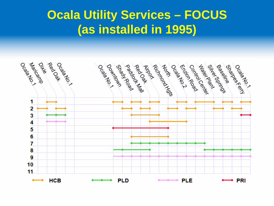
Ocala Utility Services – FOCUS(as installed in 1995)
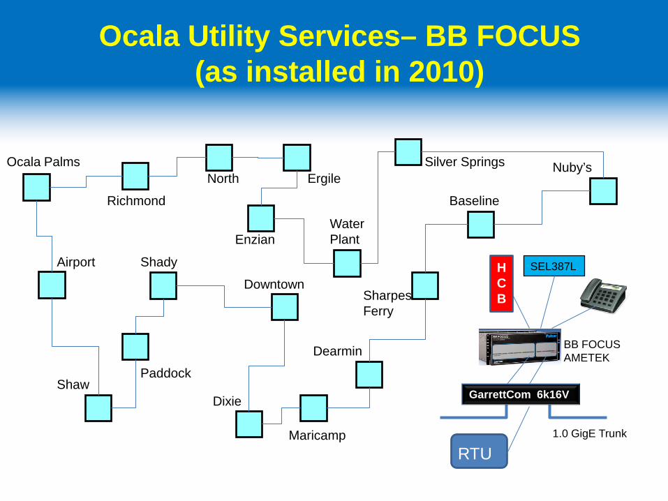
Ocala Utility Services– BB FOCUS(as installed in 2010)
Shady
Richmond
North Ergile
Enzian
Nuby’s
WaterPlant
Silver Springs
Baseline
Maricamp
DixieShaw
Airport
Paddock
DowntownSharpesFerry
Ocala Palms
Dearmin
GarrettCom 6k16V
RTU
HCB
SEL387L
BB FOCUSAMETEK
1.0 GigE Trunk

American Electric PowerBPLC Installation
Amperion Phoenix Gateway SG-5000
(BPLC Modem and Switch)
Amperion BPLC
Coupler
SEL 311L
GE L90
AMETEK BB FOCUS

Five Mile 69kV Network at AEP Field trials 2010
W Granville Granville Heath
Phoenix
69kV Circuit 69kV Circuit
Phoenix Laptop
NMS
Telular
Phoenix
NMS
Telular
camera
G.703Mirrored Bits Mirrored Bits
L 90SEL 421
G.703
BB FOCUS
SEL 421L 90
BB FOCUS
100MB FE 100MB FE
Field Test Results Summarized for L90
• Relay trip time for faults at 50% of line ranged from 38 to 42 milliseconds
• Similar results for faults at 5% and 95 %• No trips for external faults• Results were similar to tests in lab prior to field
implementation• Results were about 20 milliseconds slower than a
point to point fiber channel