Embed Size (px)
Citation preview
. .
EURAC
I.
i
Pi. KLey and G.R. Bishop Cmmissionof theEuropeenCommunities Joint Research Centre -~ Ispra EstabU.shmex3.t 21020~ rspra tva) - rtzdy
‘i .-
Contribution to the~lnternetional CoLLabxationon Advanced Neutron Sources, ICANS-L?tII Meeting, Rutherford Appleton Lekmtory, Oxford, July 8-12, 1985
June, 1985
1
“. I
. : ,
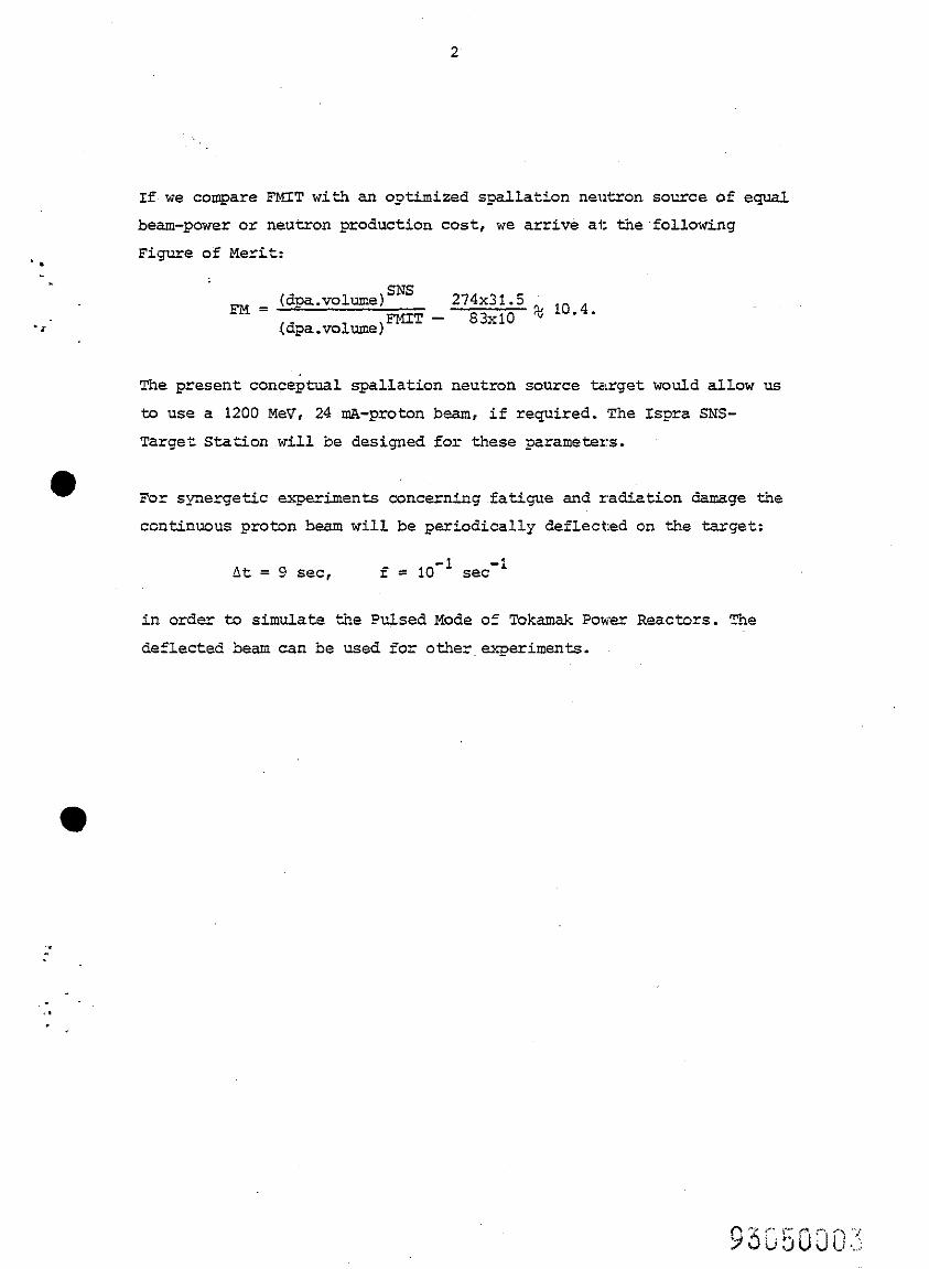
SUMMARY
The United States Department of Energy has spent in the iast 10 years
more than 100 -Mill U.S.8 for the development of intense neutron sources
for a fusion reactor material test and development programme based on
the D+-T and D*-Li stripping reaCtiOnS. The final d,esign parameters
for the large Fusion Materials Irradiator Test (FMI'T) facility are:
- Linear Accelerator: . 35 MeV, ZOO mA-deuteron-beam on a lipid
lithium target
- Irradiation parameters: . 83 d&year* in 10 cm3
. 11 He appm/dpa*.
For the last 6 years we examined the use of a Spall&cion Neutron Source
(SNS) as an alternative European Option to EMIT. For an optimised
spallation neutron source design we find~now for the same beam power
as FMIT the following design parameters:
- Linear Accelerator:‘ . 600 MeV, 6 m-A-proton beam on liguid lead
tzrget
- Irradiation parameters: . 320 dpa/year in 20 cm3-or 274 d&year in
31.5 cm3
. 6 < He appm/dpa z 13**
For a Tokzmak Evimental. Power Reactor such as INT3R (1.3 MWatt/m2
wall loading) the design parameters are:
15 dpa/year and 11 He e.ppl/dpa.
*dpa is displacements per atom; appm is atoms ,parts per million.
**A value of 6.4 is obtained if all neutrons above 30 MeV are collected in the energy group between 29.95 : 30 MeV and their He-production es- timated with On,a (30 MeV). A value of 13 is obtained if the He-pro- duction is Calculated with estimated~~,~ -crosssections for neutrons up to 400 MeV and measured neutron spectrum in excellent agreement wit?? Fusion Reactor First Wall conditions.
*.
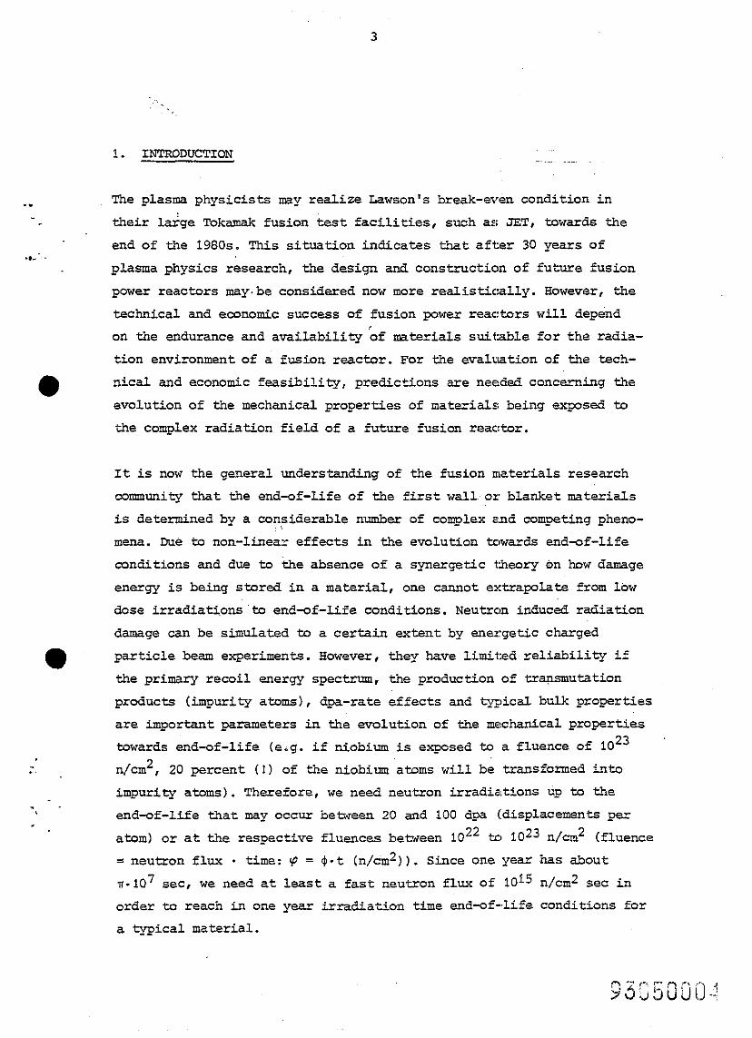
If we compare FMIT with an optimized spalla tion neutron source of equal beam-power or neutron production cost , we arrive at the~following Figure of Merit:
. i
FM = (dpa.voluma)sNs /dpa.volume)mT -
The present conceptual spallation neutron source target would allow us to use a 1200 MeV, 24 mA-proton beam, if required. The Lspra SNS- Target Station will be designed for these parameters.
For synergetic experiments conce?znixg fatigue and radiation darmge the ccntinuous proton beam will be periodically deflected on the target:
&t = 9 set, f = 10 -1 SeC
-:
in orde- to simulate the Pulsed Mode of Tokamk Power Reactors. The
deflected beam can be used for other experiments.
3
. .
.,.‘,
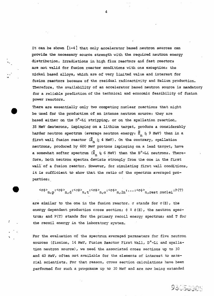
1. INTRODUCTION
The plasma physicists may realise Lawson's break-even condition in
their large Tokamak fusion test facilities , such as JET, towards the end of the 1980s. This situation indicates that after 30 years of
plasma physics research, the design and construction of future fusion
power reactors may,be considered now more realistically. However, the
technical and economic success of fusion power reactors will depend on the endurance and availability of materials suitable for the radia-
tion environment of a fusion reactor. For the evaluation of the tech-
nical and economic feasibility, predictions are needed concerning the
evolution of the mechanical properties of materials being exposed 'oo
the complex radiation field of a future fusion reactor.
It is now the general under&&ding of the fusion materials research
community that the end-of-life of the first wallor blanket materials
is determined by a considerable number of complex and competing pheno-
mena. Due to non-linear effects in the evolution towards end-of-life
conditions and due to the absence of a synergetic theory on how damage
energy is being stored in a material , one cannot extrapolate from low
dose irradiations'to end-of-life conditions. Neutron induced radiation
damage can be simulated to a cextain extent by energetic charged
particle beam eeeriments. However, they have limited~reliability if
the primary recoil energy spec+-, the production of transmutation
products (impurity atoms), dpa-rate effects and typical bulk properties
are important parameters in the evolution of the mechanical properties
towards end-of-life (e.g. if niobium is exposed to a fluence of lO23
n/cm*, 20 percent (!) of the niobium atoms will be transformed into
impurity atoms). Therefore, we need neutron irradiations up to the
end-of-life that may occur between 20 and 100 dya (displacements per
atom) or at the respective fluences between lo** to fO23 n/cm* (fluence
= neutron flux . time: 9 = 4-t (~/&II*)). Since one year has about
n-lo7 set, we need at least a fast neutron flux of 10f5 n/cm* set in
order to reach in one year irradiation time end-of-life conditions for
a typical material.
4
. ,h’ / ,
It can be shown [l-4] that only accelerator based neutron sources can
provide the necessary source strength with the required neutron energy
distribution. Irradiations in high flux reactors and fast reactors
are not valid for fusion reactor conditions with one exception: the
nickel based alloys, which are of very limited value and interest for
fusion reactors because of the residual radioactivity and Helium production. Therefore, the availability of an accelerator based neutron source is mandatory
for a reliable prediction of the technical and economic feasibility of fusion power reactors.
There are essentia~lly only two competing nuclear reactions that might
be used for the production of an intense neutron source: they are
based either on the D+-Li stripping, or on the spallation reaction.
35 MeV deuterons, impinging on a lithium target, produce a considerably
harder neutron spectrum (average neutron energy: En &! 9 MeV) than in a
first wall fusion reactor (En 2 4 Mev). On the contrary, spallation
neutrons, produced by 600 MeV protons impinging on a lead target, have
a somewhat softer spectrum (En a 6 MeV) than the D+-Li neutrons. There- .' fore, both neutron spectra deviate strongly from the one in the first
wall'of a fusion reactor. However, for simulating first w&L1 conditions,
it is sufficient to show that the ratio of the spectrum averaged pro-
perties:,
<a+> wp
:<a$> .:a$> ha n,t :a$> n u:<um’ n,2n :...:<u$> , n,rest nuclei'P(T)
are similar to the one in the fusion reactor. u stands for o(E), the
energy dependent production cross section; Q S 6(E), the neutron spec-
trum; and P(T) stands for the primary recoil energy spectrum; and T for
the recoil energy in the laboratory system.
For the evaluation of the spectrum averaged parameters for five neutron
sources (fission, 14 KsV, Fusion Reactor First Wall, D+-Li and spalla- tion neutron source), we need the associated cross sections up to 30
and 40 MeV, often not available for the elements of interest to mate-
rial scientists. For that reason, cross section calculations have been
performed for such a programme up to 30 MeV and are now being extended
. .
.,*-
0
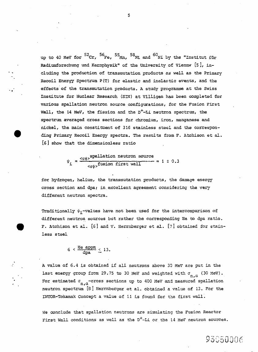
up to 40 MeV for 52Cr, 56Fe, '%n, 'SNi and 6oNi by the "Institut fGr
Radiumforschung und Kernphysik" of the University of Viennw [51, in-
eluding the production of transmutation products as well as the Primary
Recoil Energy Spectrum P(T) for elastic and inelastic events, and the
effects of the transmutation products. A study programme at the Swiss
Institute for Nuclear Research (SIN) at Villigen has been completed for
various spallation neutron source configurations, for the Fusion First
Wall, the 14 MeV, the fission and the DC-Li neutron spectrum, the
spectrum averaged cross sections for chromium, iron, manganese and
nickel, the main constituent of 316 stainless steel and the correspon-
ding Primary Recoil Energy spectra. The results from F. htchison et al.
[6] show that the dimensionless ratio
tJi = <a4,s_Dallation neutron source
fusion first wall = 1 f 0.3 <aQ >
for hydrogen, helium, the transmutation products, the damage energy
cross section and dpa; in.excellent agreement considering the very
different neutron spectra.
Traditionally ei-values have not been used for the intercomparison of
different neutron sources but rathe r the corresponding He to dpa ratio.
F. Atchison et al. [6] snd V. Zerrnberger et al. [71 obtained for stain-
less steel
-. '
A value of 6.4 is obtained if all neutrons above 3,3 MeV are put in the
last energy group from 29.75 to 30 MeV and weight& with on,& (30 MeV).
For estimated an Q -cross secticns up to 400 MeV and measured spallation ,
neutron spectrum [81 Herrnberger et al. obtained a value of 13. For the
INTCR-Tokamak Concept a value oL * 11 is found for the first wall.
We conclude that spallation neu trons are simulating the Fusion Reactor
First Wall conditions as well as the D+ -Li or the 'L4 MeV neutron SOUZTSS.
6'
.
.;'
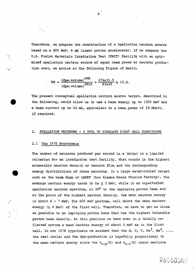
Therefore, we propose the construction of a spallation neutron source
based on a 600 MeV, 6 IDA linear proton accelerator. If we compare the
U.S. Fusion Materials Irradiation Test @MIT) facility with an opti-
mized spallation neutron source of equal beam powc?r or neutron produc-
tion cost, we arrive at the following Figure of Merit:
FM = (dpa.volume)SNS = 274x31.5
(dpa.volumeJFMIT 83x10 ' 'Oe4'
The present conceptual spallation neutron source target, described in
0 the following, would allow us to use a beam energy up to 1200 MeV and
a beam current up to 24 mA, equivalent to a beam power of 29 Miiatt,
if required.
2. SPALLATION NEUTRONS - A TOOL To SIMIJIATH FIRST 5FJ.L CONDITIONS
2.1 The 1978 Xypothesis
The number of neutrons produced per second in a target is a limited
criterion for an iaadiation test facility. What counts is the highest
accessible neutron density or neutron flux and the corresponding
e energy distributions of these neutrons. In a large watsr-cooled Xarget
such as the beam dump of WMPF (Los Alams Meson Physics Factory), the
average neutron energy tends to be $ 2 MeV, while in an unperturbed
spallation neutron spectrum, at 90° to the impinging proton beam aud
at the point of the highest neutron density, the mean neutron energy
is about 6 - 7 MeV, for 600 MeV protons, well above the mean neutroc
energy (% 4 MeV) of the first wall. Therefore, we have to get as close . as passtile to an impinging proton beam that has the highest tolerable
proton beam density. At this position we have even in a totally re-
flected system a mean neutron energy of about 4 MeV as in the first
wall. In our 1978 hypothesis we assumed that the H, D, T, He3, Xe4 , . . . . the rest nuclei and the dpa-production is hopefully proportional to
the mean neutron energy since the an,p(E) and c,,,(E) cross sections
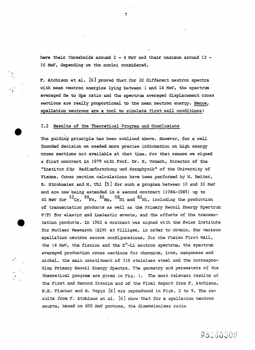
have their thresholds around 2 - 4 tfev and their maximum around 13 -
16 MeV, depending on the nuclei considered.
. _. ,
F. Atchison et al. [61 proved that for 20 different neutron spectra
with mean neutron energies lying between 1 and 14 MeV, the spectrum
averaged He to dpa ratio and the spectrum averaged. displacement cross
sections are really proportional to the mean neutron energy. Hence,
spallation neutrons are a tool to simulate first wall conditions!
2.2 ResuLts of the Theoretical Program and Conclusions
The guiding principle has been outlined above. However, for a well
founded decision we needed more precise information on high energy
cross sections not available at that time. For that reason we signed
a first contract in 1979 with Prof. Dr. H. Vonach, Dit‘ector of the
"Institut fiir Radiumforschurqund Kernphysik" of the University of
Vienna. Cross section calculations have been performed by W. Rsiter,
B. Strohmaier and M. UN [51 for such a program between 10 and 30 MeV
and are now being extended in a second contract (1984-1985) up to
d0 MeV for 52Cr, 56Fe, 55Mn, 58Ni and 6o Ni, including the production
of transmutation products as well as the Primary Recoil Energy Spec~kxm
P(T) for eiastic and inelastic events, and the effects of the transmu-
tation products. In 1982 a contract was signed wit!1 the Swiss Institute
for Nuclear Research (SIN) at Villigen, in order to obtain, for various
spallation neutron source configxations, for the Fusion First Wall,
the 14 ReV, the fission and the D*-Li neutron spedrum, the spectrum
averaged production cross sections for chromium, iron, manganese and
nickel, the main constitxnt of 316 stainless steel. and the correspon-
ding Primary Recoil Energ Spectra. The geometry and parameters of the
theoretical program are given in Fig. 1. The most relevant results of
the First and Second Interim and of the Final Report from F. Atchison,
W.E.'Fischer and M. Pepin [61 are reproduced in Figs. 2 to 9. The re-
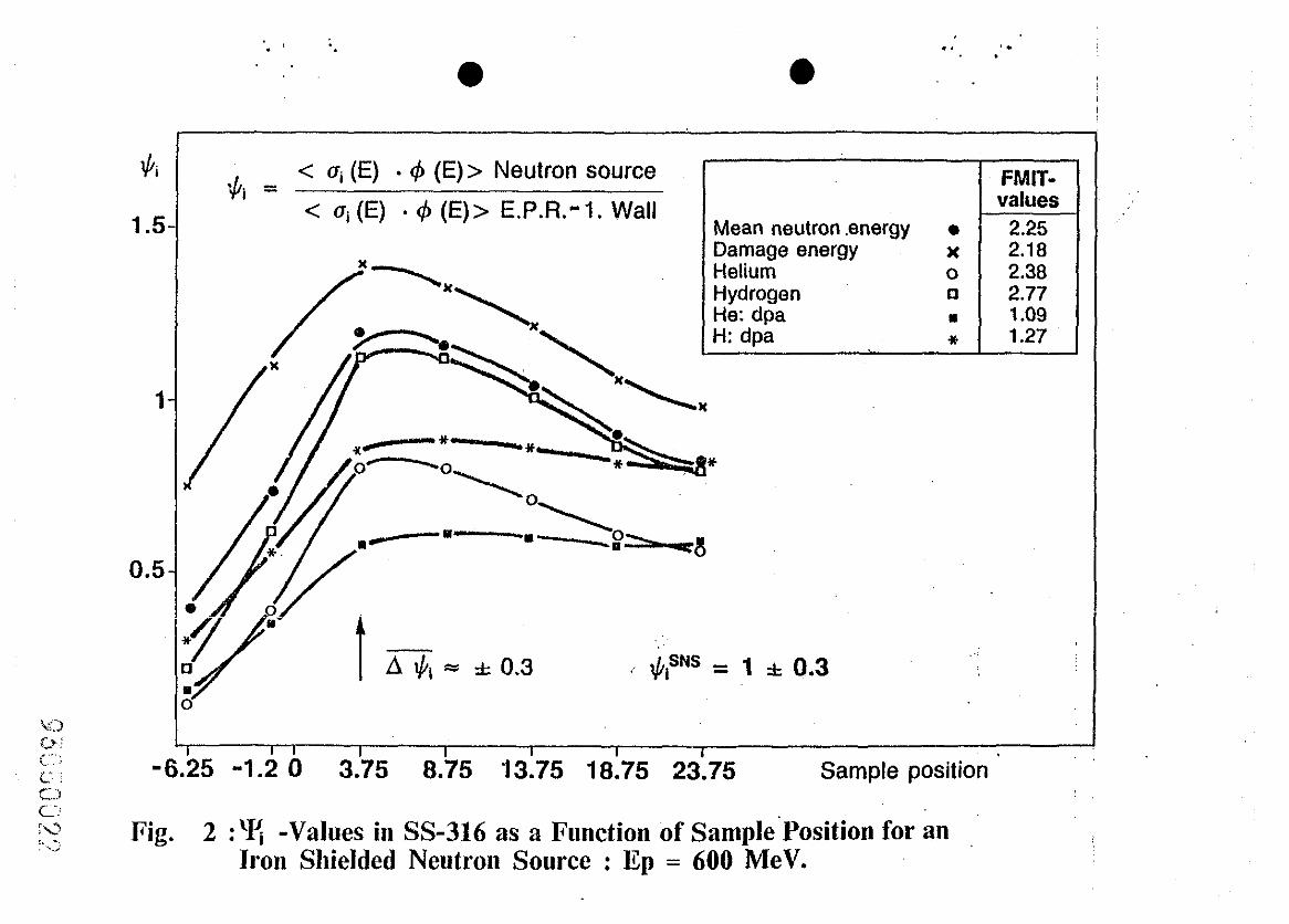
sults from F. Atchison et al. [6] show that for a spallation neutron
source, based on 600 NeV protons, the dimensionless ratio
8
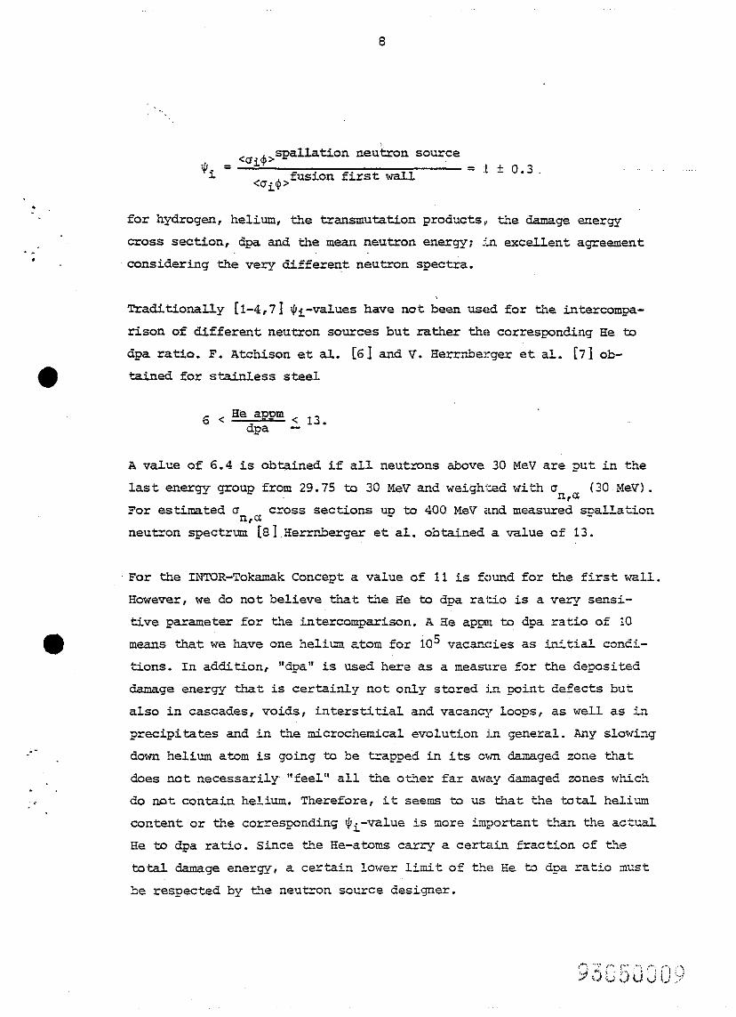
@a = <Oi.V spallation neutron source
IL fusion first wall = :L k 0.3 <Ui$'
.
l
_--
. ,=
for hydrogen, helium, the trsnmutation products,, the damage energy
cross section, dpa and the mean neutron energy; in excellent agreement
considering the very different neutron spectra.
Traditionally [l-4,71 I)- L-values have not been used for the intercompa-
risen of different neutron sources but rather the corresponding He to
dpa ratio. F. Atchison et al. [61 and V. Herrnberger et al. [71 ob-
tained for s&&less steel
6 < He appm dpa 2 13.
A value of 6.4 is obtained if all neutrons above 30 MeV are put in the
last energy group from 29.75 to 30 MeV and weighted with mn c( , (3o~xev).
For estimated o n cf cross sections up to 400 P&V and measured spallation
neutron spectrum'[81 Herrnberger et al. obtained a value of 13.
For the INTOR-Tokamak Concept a value of 11 is found for the first wall.
However, we do not believe that the He to dpa ratio is a very sensi-
tive parameter for the intercomparison. A Se appm to dpa ratio of i0
means 'A-tat we have one helium atom for iC15 vacancies as initial condi-
tions. In addition, "dpa" is used here as a measure for the deposited
damage energy that is certainly not only stored in point defects but
also in cascades, voids, interstitial and vacancy loops, as well as in
precipitates and in the microchemical evolution in general. Any slowing
down helium atom is going to be trapped in its own damaged zone that
does not necessarily "feel" all the other far away damaged zones which
do not contain helium. Therefore, it seems to us that the total helium
content or the correqonding $~~-value is more important than the actual
He to dpa ratio. Since the He-atoms carry a certain fraction of the
total damage energy , a certain lower limit of t:he Se to dpa ratio must
be respected by the neutron source designer.
9
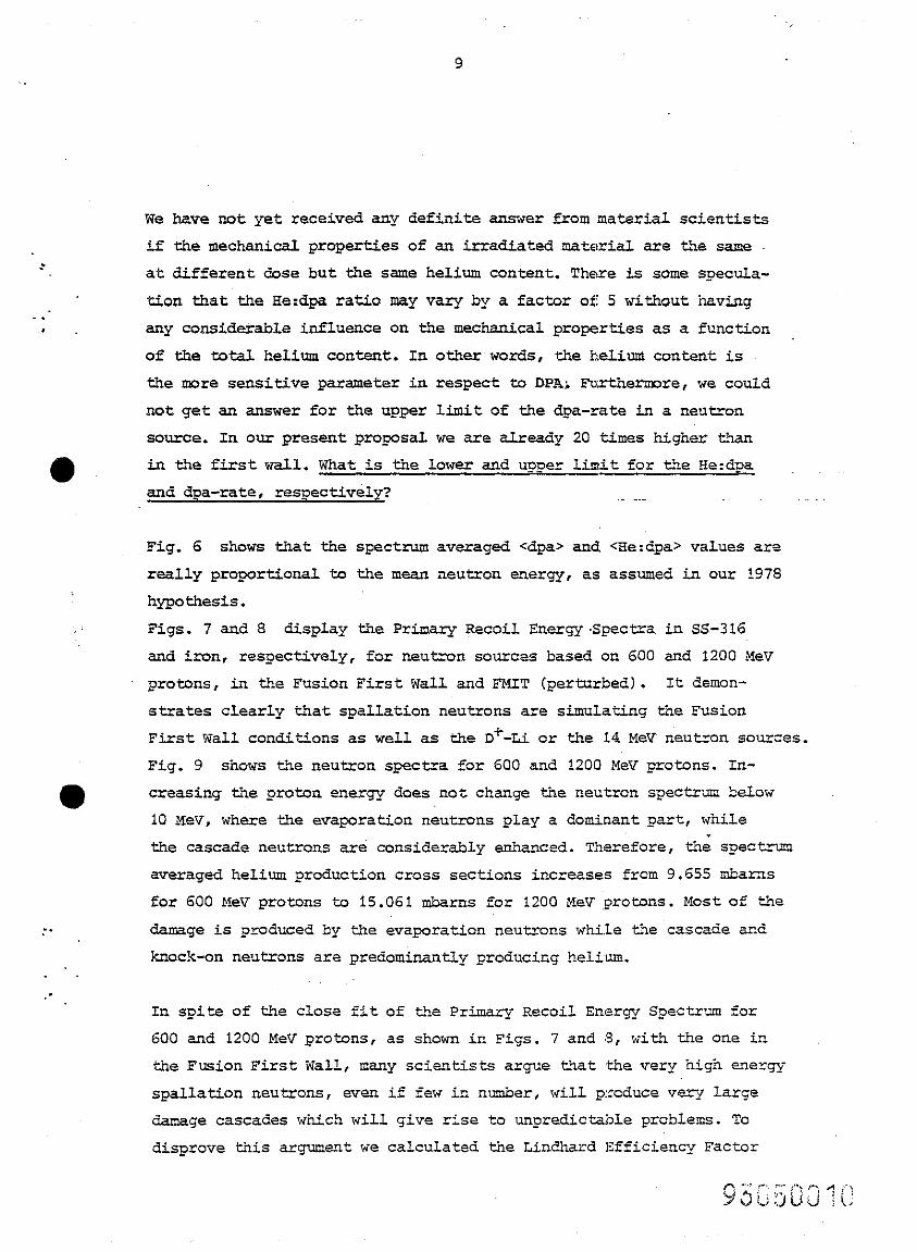
We have not yet received any definite answer from natarial scientists
if the mechanical properties of an irradiated material are the same
at different dose but the same helium content. There is some specula-
tion that the He:dpa ratio may vary by a factor of 5 without having .: . any considerable influence on the mechanical properties as a function
of the total helium content. In other words, the helium content is
the more sensitive parameter in respect to DPA; Furthermore, we could
not get an answer for the upper limit of the dpa-rate in a neutron
source. In our present pro_wsal we are already 20 times higher than
0. in the first wall. What is the lower and upper limit for the He:dpa
and dpa-rate, respectively?
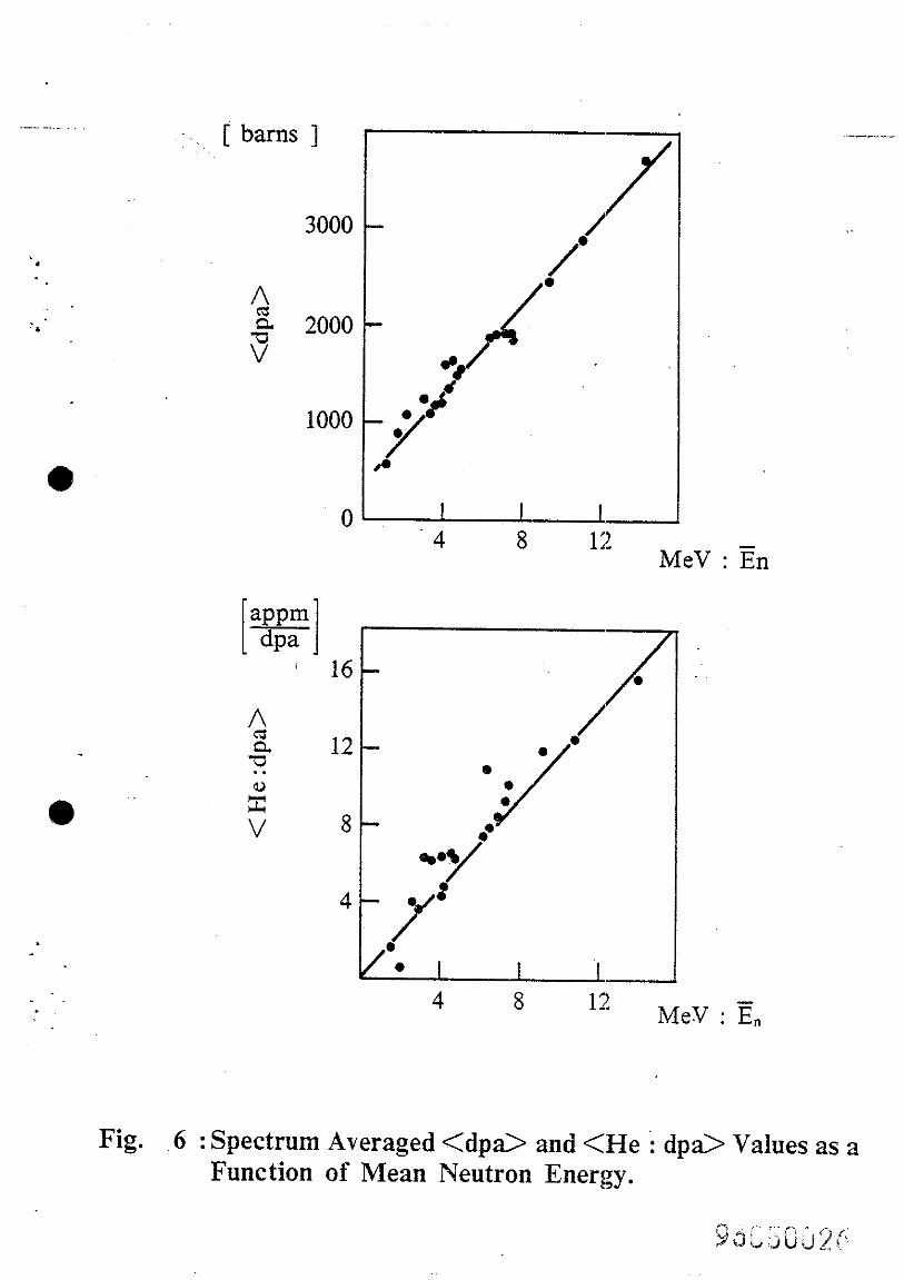
Fig. 6 shows that the spectrum averaged <dpa> and <Re:dpa> values are
really proportional to the mean neutron energy , as assumed in our 1978
hypothesis.
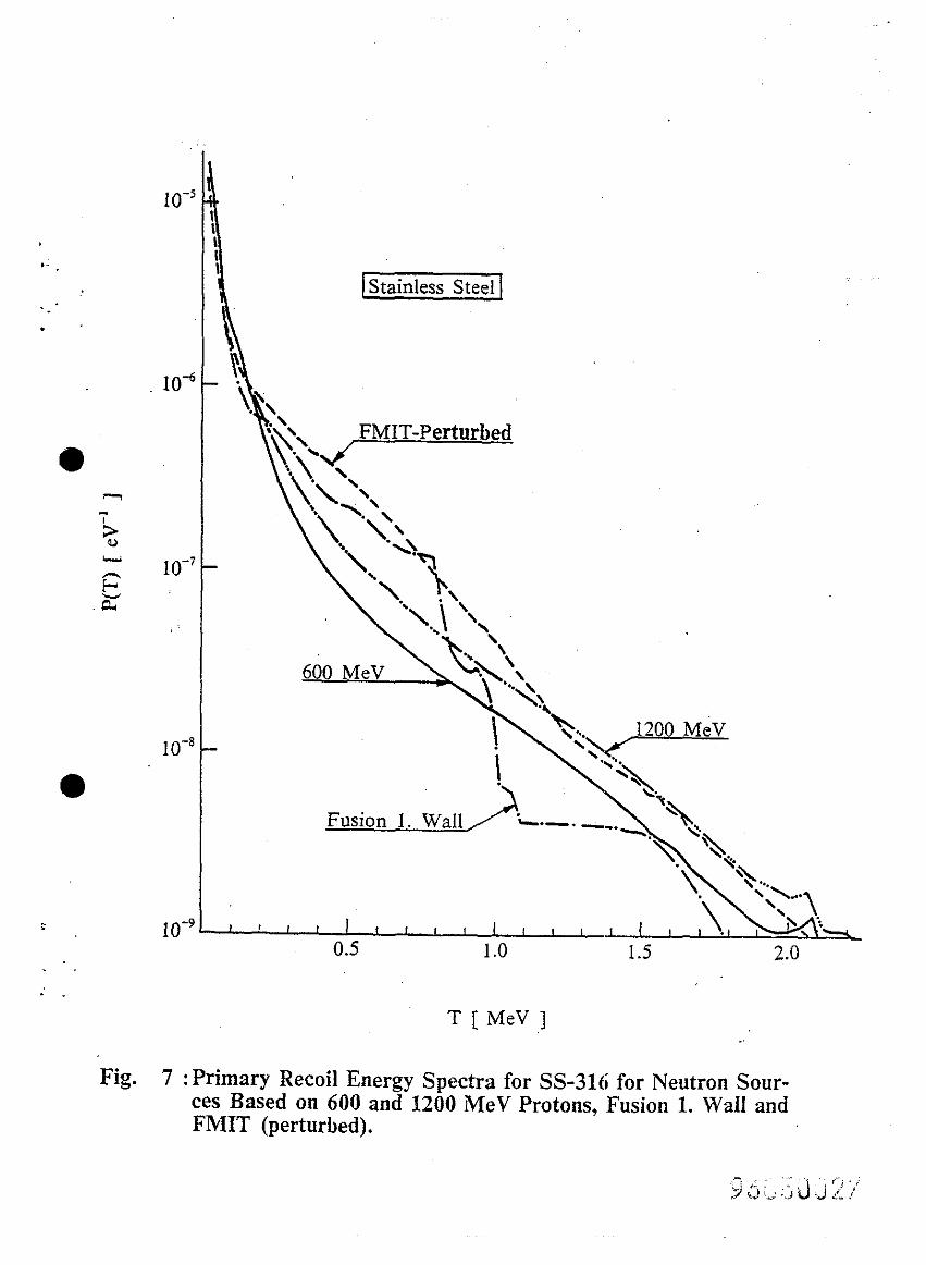
Figs. 7 and 8 display the Primary Recoil Energy Spectra in sS-316
and iron, respectively, for neutron sources based on 600 and 1200 XeV
protons, in the Fusion First Wall and FMIT (perturbed). It demon-
strates clearly that spallation neutrons are simulating the Fusion
First Wall conditions as well as the D+-Ii or the 14 MeV neutron sources.
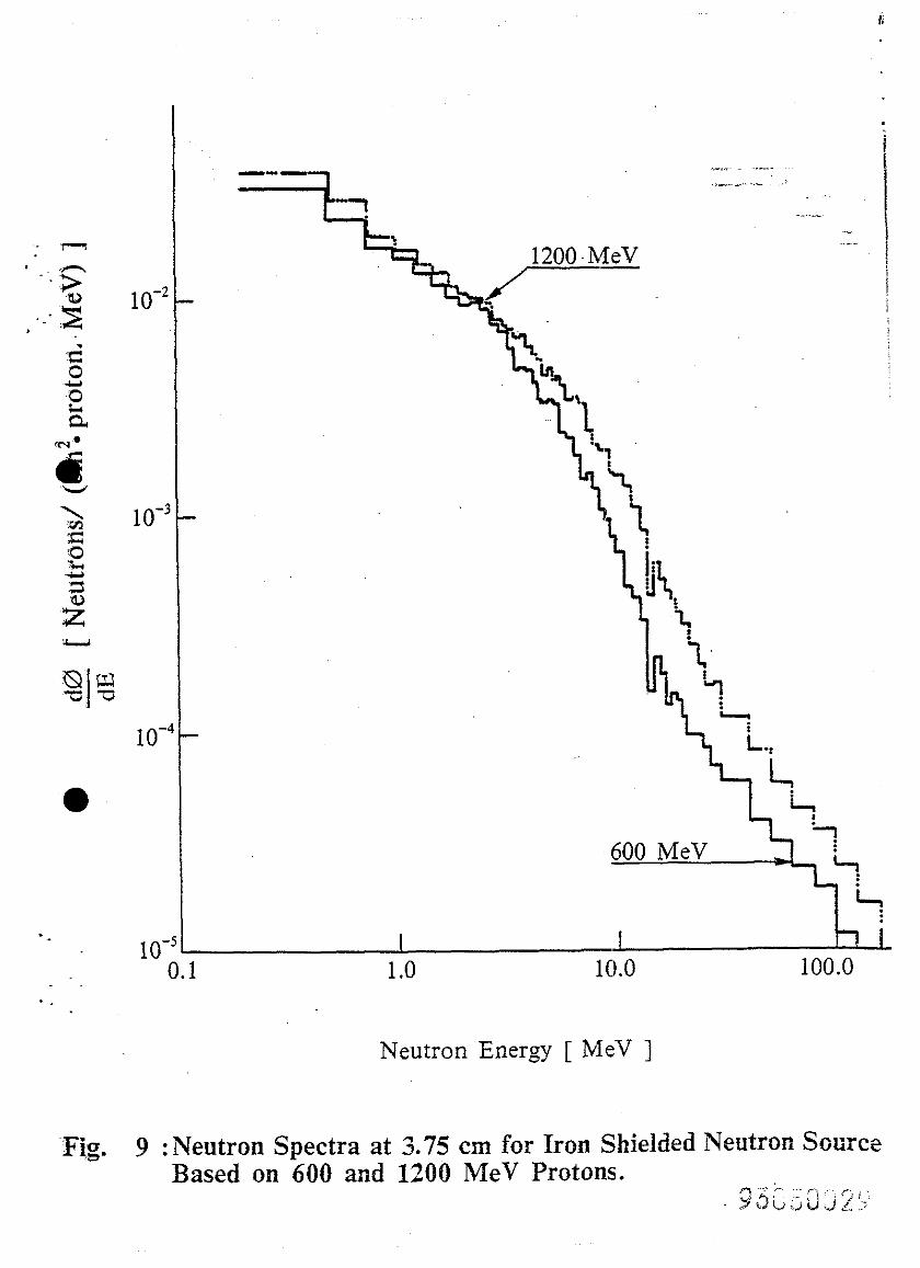
Fig. 9 shows the neutron spectra for 600 and 1200 MeV protons. In-
@ creasing the proton energy does no t change the neutron spectrum below
10 XeV, where the evaporation neutrons play a dominant part, while
: .
the cascade neutrons are considerably enhanced. Therefore, the spectrum
averaged helium production cross sections increases from 9.655 mbarns
for 600 MeV protons to 15.061 mbarns for 1200 MeV :protons. Most of the
damage is produced by the evaporation neutrons while the cascade and
knock-on neutrons are predominantly producing helium.
In spite of the ClOSe fit of the Primary Recoil Ensaqy SpeCtr’;m for
600 and 1200 MeV protons, as shown in Figs. 7 and 8, with the one in
the Fusion First Wall, many scientists argue that ,the very high energy
spallation neutrons, even if few in n-umber, will prcduce veq large
damage cascades which will give rise to unpredictable problems. To
disprove this argument we calculated the Lindhard Efficiency Factor
10
. .
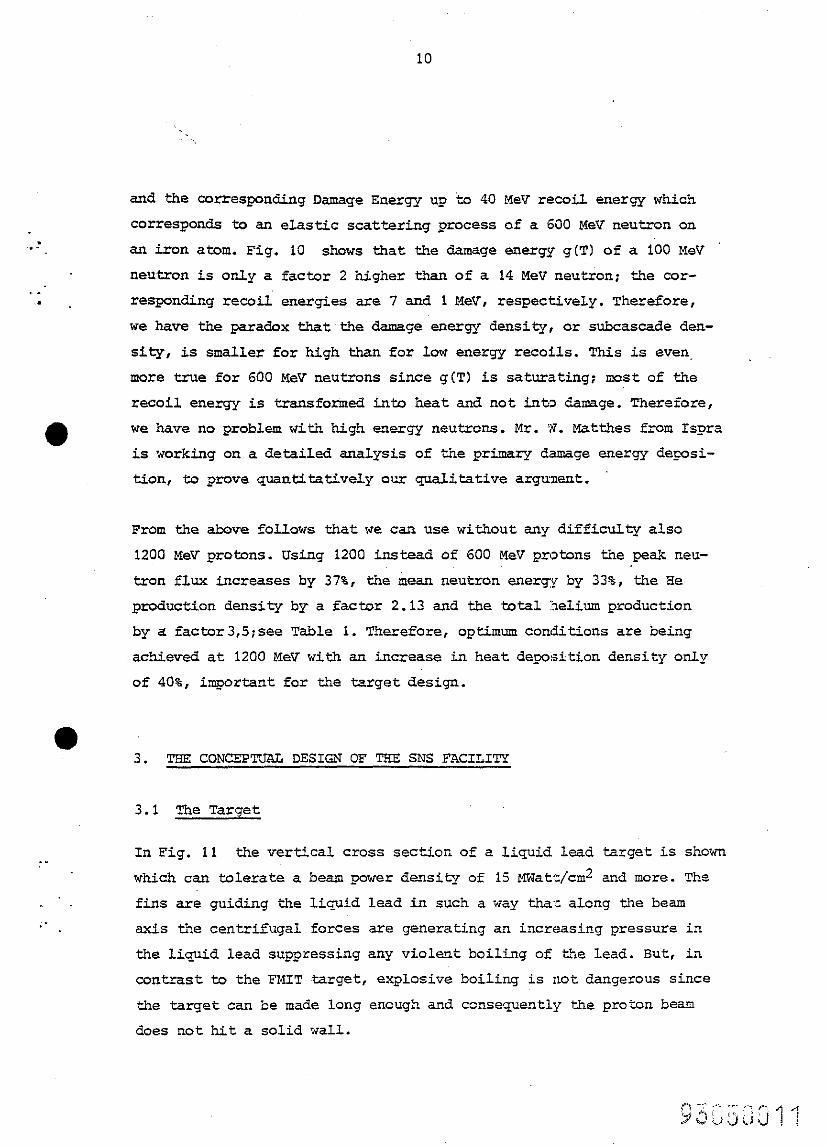
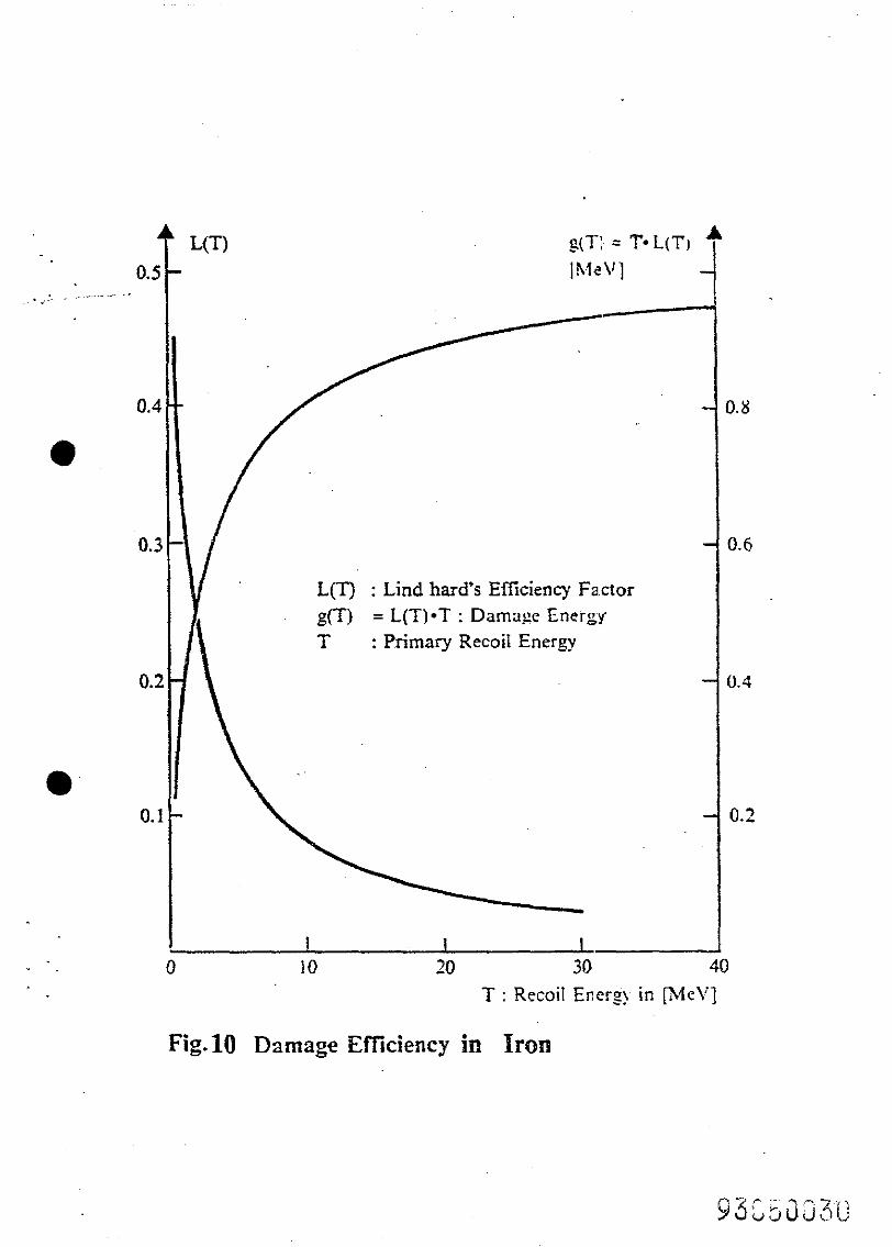
and the Corresponding Damage Energy us to 40 MeV recoil energy which
COrresponds to an elastic scattering process of a 600 MeV neutron on
an iron atom. Fig. 10 shows that the damage energy g(T) of a 100 XeV
neutron is 0rQ.y a factor 2 higher than of a 14 MeV neutron; the cor-
responding recoil energies are 7 and 1 MeV, respectively. Therefore,
we have the paradox that the damage energy density, or subcascade den-
sity, is smeller for high than for Low energy recoils. This is even,
more true for 600 MeV neutrons since g(T) is saturating; most of the
recoil energy is transformed into heat and not into damage. Therefore,
a we have no problem with high energy neutrons. Mr. '77. Matthes from Ispra
is working on a detailed analysis of the primary damage energy depsi-
tion, to ?rove quantitatively our qualitative argument.
From the above follows that we can use without any difficulty also
1200 MeV protons. ITsing 1200 instead of 600 MeV protons the peak neu-
tron flux increases by 3?%, the mean neutron energy by 33%, the EIe
production density by a factor 2.13 and the total :helium production
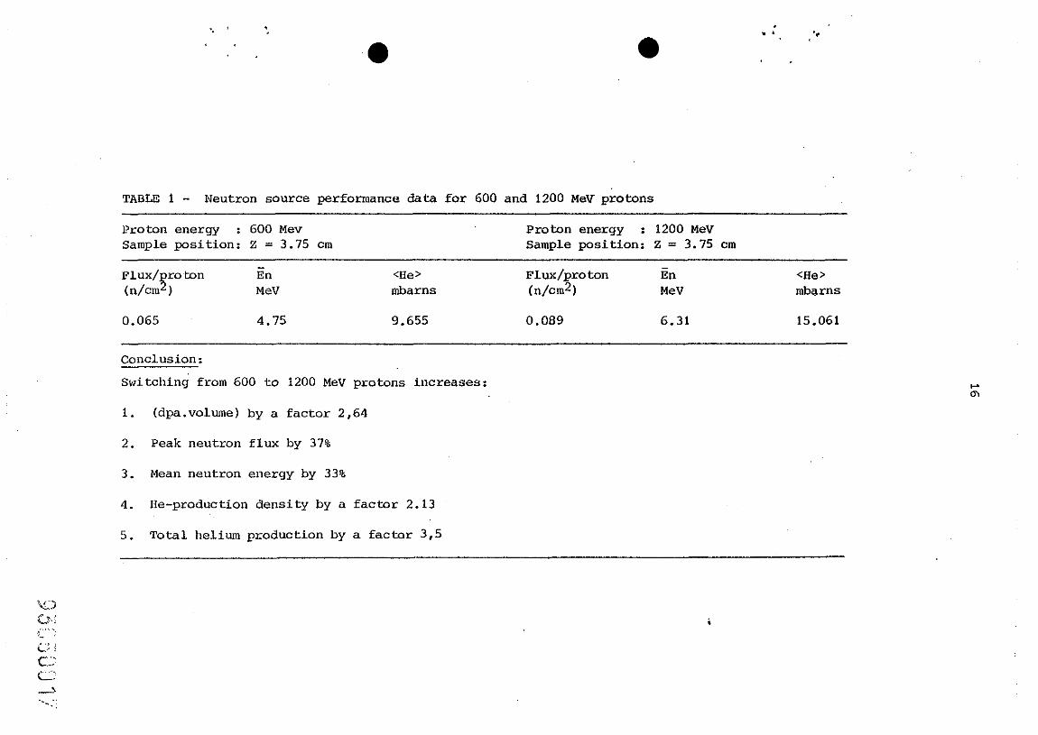
by a factor3,S;see Table 1. Therefore , optiinum conditions are being
achieved at 1200 MeV with an increase in heat deposition density only
of 40%, important for the target design.
. THE CONCEFTJAL DESIGN OF TBB SNS E'ACILITY
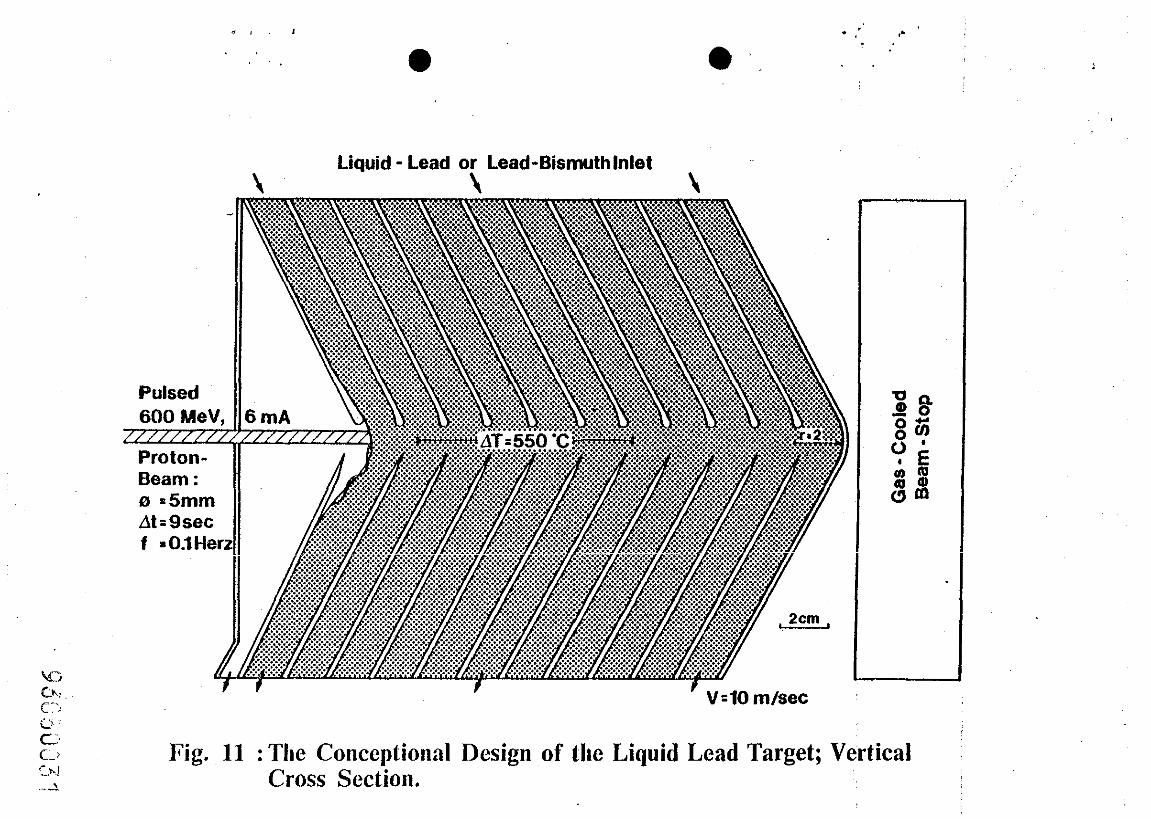
3.1 The Target
In Fig. 11 the vertical cross section of a liquid lead target is shown
which can tolerate a beam power density of 15 MWat.l/cm2 and more. The
fins are guiding the liquid lead in such a way that along the beam axis the centrifugal forces are generating an increasing pressure in
the liquid lead suppressing any violent boiling of the lead. But, in
contrast to the FMIT target, explosive boiling is not dangerous since
the target can be made long encugh and consequently the proton bean
does not hit a solid wall.
11
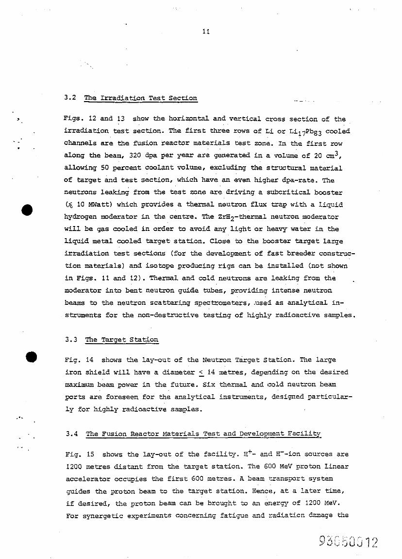
3.2 The Irradiation Test Section
.V
. _’ m
l
. - -
.
I _
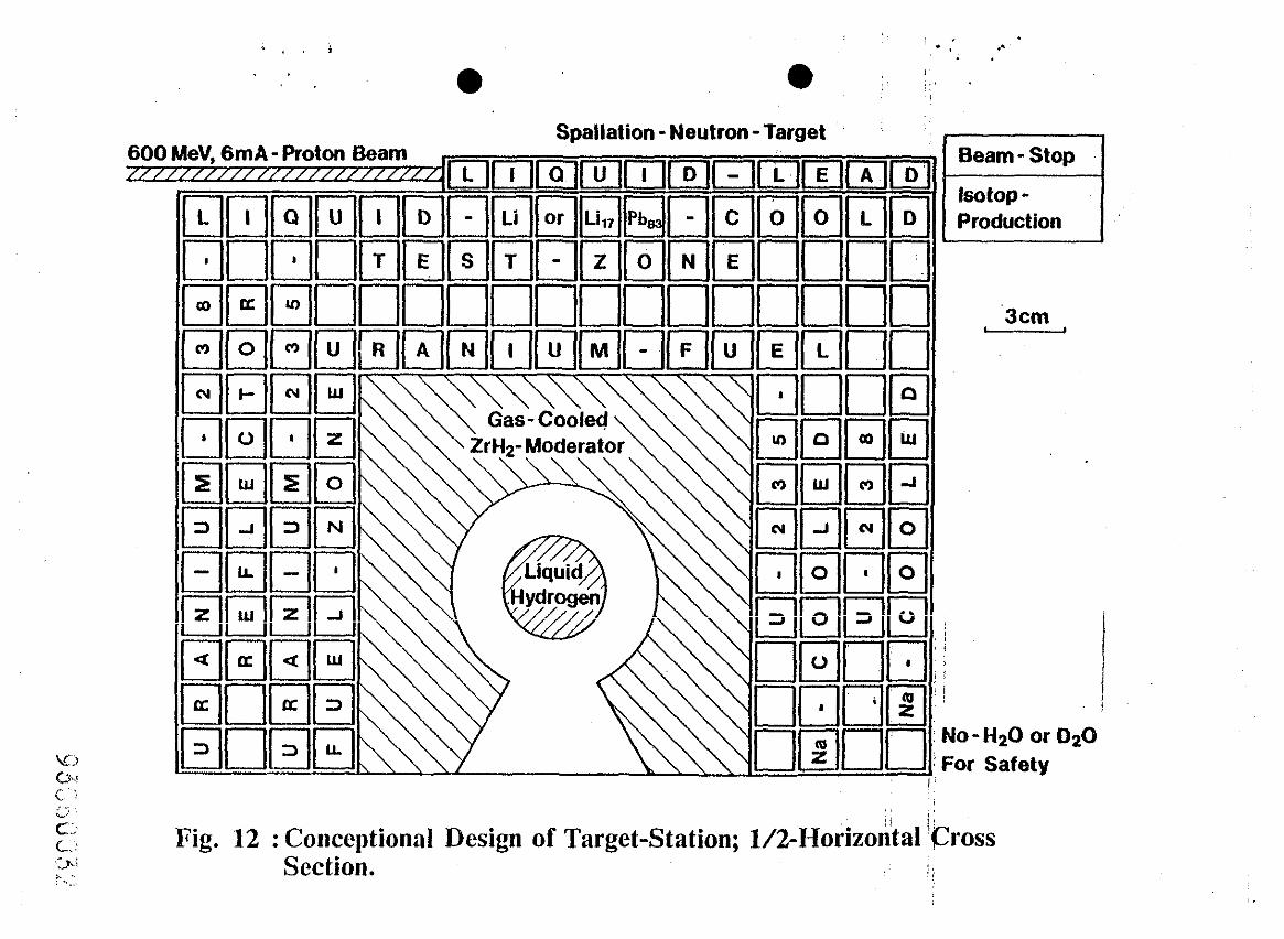
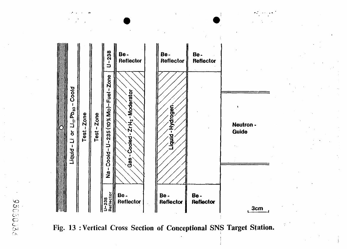
Figs. 12 and 13 show the horiwn+;tl and vertical cross section of the
irradiation test section. The first three rows of Li or Li17PbS3 cooled
charnels are the fusion reactor materials test zone. In the first row
along the beam, 320 dpa per year are generated in a volume of 20 cm3,
allowing 50 percentcoolantvolume , excluding the structural material
of target and test section , which have an even higher dpa-rate. The
neutrons le&& from the test zone are driving a subcritical booster
(6 10 MWatt) which provides a thermal neutron flux trap with a l&Aid
hydrogen moderator in the centre. The ZrH2-thermal neutron moderator
will be gas cooled in order to avoid any light or heavy water in the
liquid metal cooled target station. Uase to the booster target large
irradiation test sections (for the development of fast breeder construc-
tion materials) and isotope producing rigs can be installed (not shown
in Figs. 11 and 12). Thermal and cold neutrons are leaking from the _
moderator into bent neutron guide tubes, providing intense neutron
beams to the neutron scattering spectrometers, usei as analytical in-
struments for the non-destructive testing of highly radioactive samples.
3.3 The Target Station
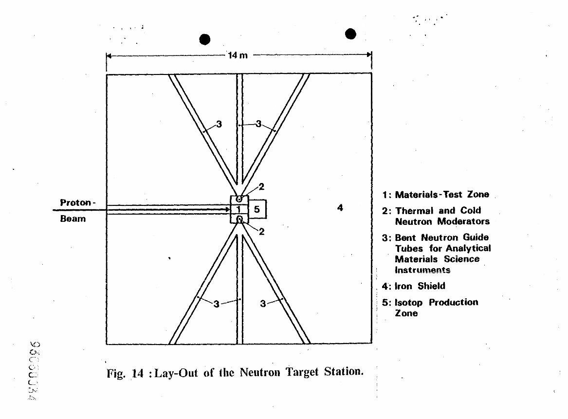
Fig. 14 shows the lay-out o f the Neutron Target Station. The large
iron shield will have a diameter < 14 metres, depending on the desired
maximum beam poner in the future. Six thermal and cold neutron beam
ports are foreseen for the analytical instruments, designed particulsr-
ly for highly radioactive samples.
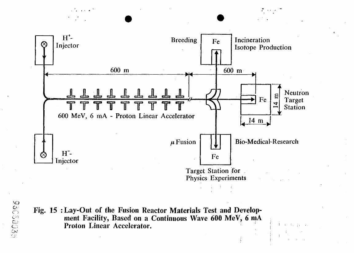
3.4 The Fusion Reactor Materials Test and Development Facility
Fig. 15 shows the lay-out of the facility. E+- and H--ion sources are
1200 metres distant from the target station. The 600 MeV proton Linear
accelerator occupies the first 600 metres. A beam transport system
guides the proton beam to the target station. Hence, at a later time,
if desired, the proton beam can be brought to an energy of 1200 Rev.
For synergetic experiments COnCerning fati gue and radiaticn damage the
12
. . .
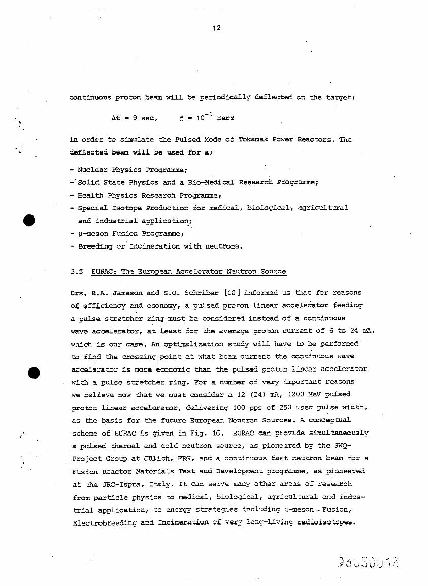
continuous proton beam will be periodically deflected on the target:
nc = 9 set, f = 10-l Her2
in order to simulate the Pulsed Mode of Tokamak Power Reactors. The
deflected beam will be used for a:
- Nuclear Physics Programme;
-'Solid State Physics and a Bio-Medical Research I?rcqramme;
- Health Physics Research Programme;
- Special Isotope Production for medical, biological, agricultural
and industrial application;
- p-meson Fusion Programme;
- Breeding or Incineration with neutrons.
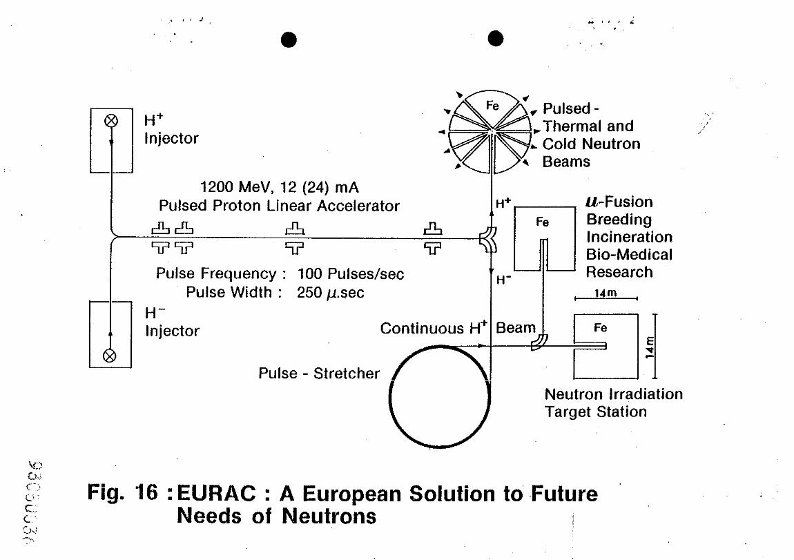
3.5 EURAC: The European Accelerators Neutron Sourt!~
Drs. R.A. Jameson and S.O. Schriber [lOI informed us that for reasons
of efficiency and economy, a pulsed proton linear accelerator feeding
a pulse stretcher ring must be considered instead of a continuous
wave accelerator, at least for the average proton current of 6 to 24 mA,
which is our case. An optimzlisation study will have to be performed
to find the crossing point at what beam current the cont.in~ous wave
accelerator is more economic than the pulsed proton linear accelerator
with a pulse stretcher ring. For a number of very important reasons
we believe now that we must consider a 12 (24) mA, 1200 MeV pulsed
proton linear accelerator, delivering 100 pps of 250 usec pulse width,
as the basis for the future European Neutron Sources. A conceptuti
scheme of EURAC is given in Fig. 16. EUFWC can provide simultaneously
a pulsed thermal and cold neutron source, as pioneered by the SNQ-
Project Group at Jiilich, FRG, and a continuous fast neutron beam for a
Fusion ReaCtOr Materials Test and Development progr-e, as pioneered
at the JRC-Ispra, Italy. it can serve many other areas of research
from particle physics to medical, biological, agricultural and indus-
trial application, to energy strategies including u-meson-Fusion,
Blectrobreeding and Incineration of very long-living radioisotopes.
13
.
. . *
l
It may be remarked that muon-Fusion is making remarkable progress
[ll-151 and it has to be considered seriously as ;a possible solution
to Our future energy requirements. To produce one u-meson an energy of about 5 GeV is necessary, therefore "break even" would be reached
at around 300 catalytic D-T muon reactions. Recently at LAEL [161,
200 muon catalytic reactions have been measured per u-meson. This is
more than expected from the theoretical sticking :factor, describing
the probability of attachment of the u-meson to the a-particle in the
D-T muon catalytic fusion process , that predicts .&out 100 reactions per muon. Two hundred reactions would be sufficient for a Hybrid-B&ion
Reac'cor.~However, the problem remains how tc collect the muons effi-
ciently from a target and to transfer them to a reaction chamber. It
seems a difficult but solveable problem. Therefore, more theoretical
and experimental work must be devoted to the collection of u-mesons.
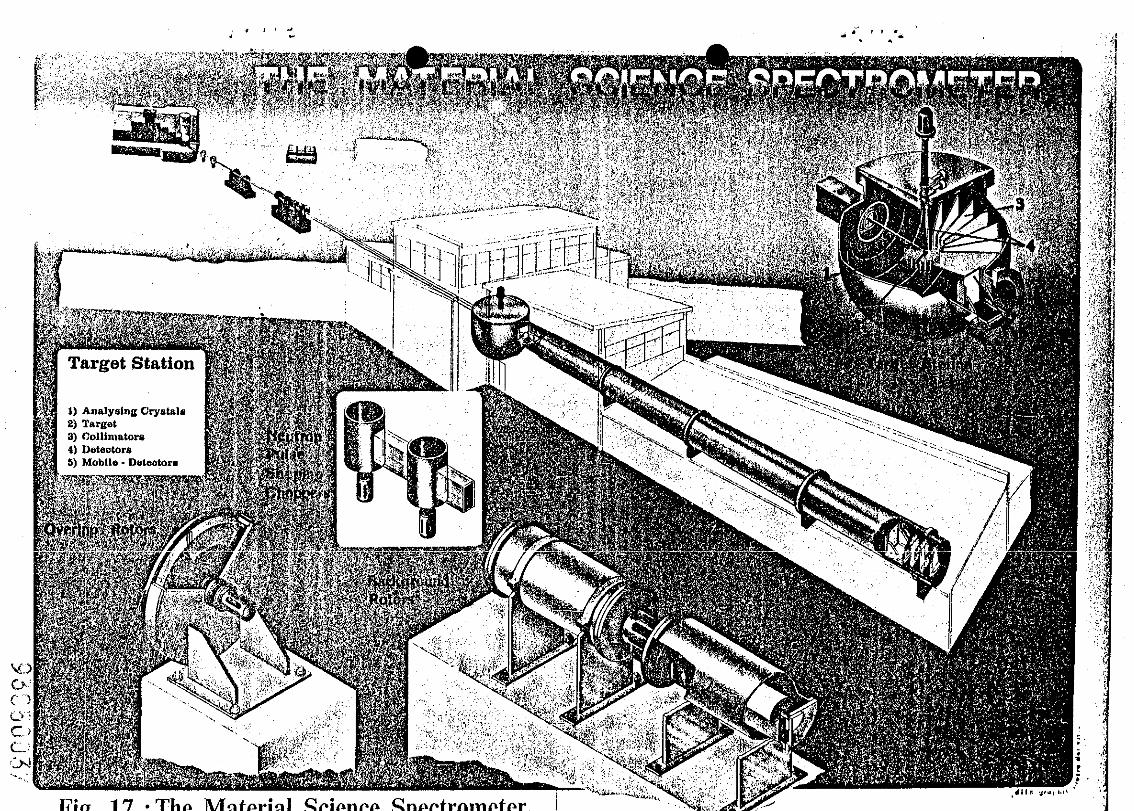
Fig. 17 shows the artistic view.of a Material~Scian-:e Spectrometer
[171 of which a 90 metre long version was designed for the SW Ruther-
ford Appleton Laboratory, UK, and a 150 metre Long version for the SNQ
Ji&ich. The foundations and the beam port insert have been constructed
at RAL and a considerable part of the detectors have been purchased.
The spectrometer is capable to measure simultaneously Small Angle
Scattering (SAS), Elastic Diffuse Scattering (EDS), Quasi Elastic
Scattering (QES) and Bragg Scattering (BSI. Therefore, the spectrometer
is capable to measure simultaneously the density of pint defects, t!ne
density ,and sire distribution of precipitates, damage cascades and
voids, the texture, the stress and strain distributions, the mobility
of hydrogen as well as the microchemical evolution of candidate mate-
rials irradiated to end-of-life conditions. The high resolution neutron
spectrometer will complement the conventional analytical instruments.
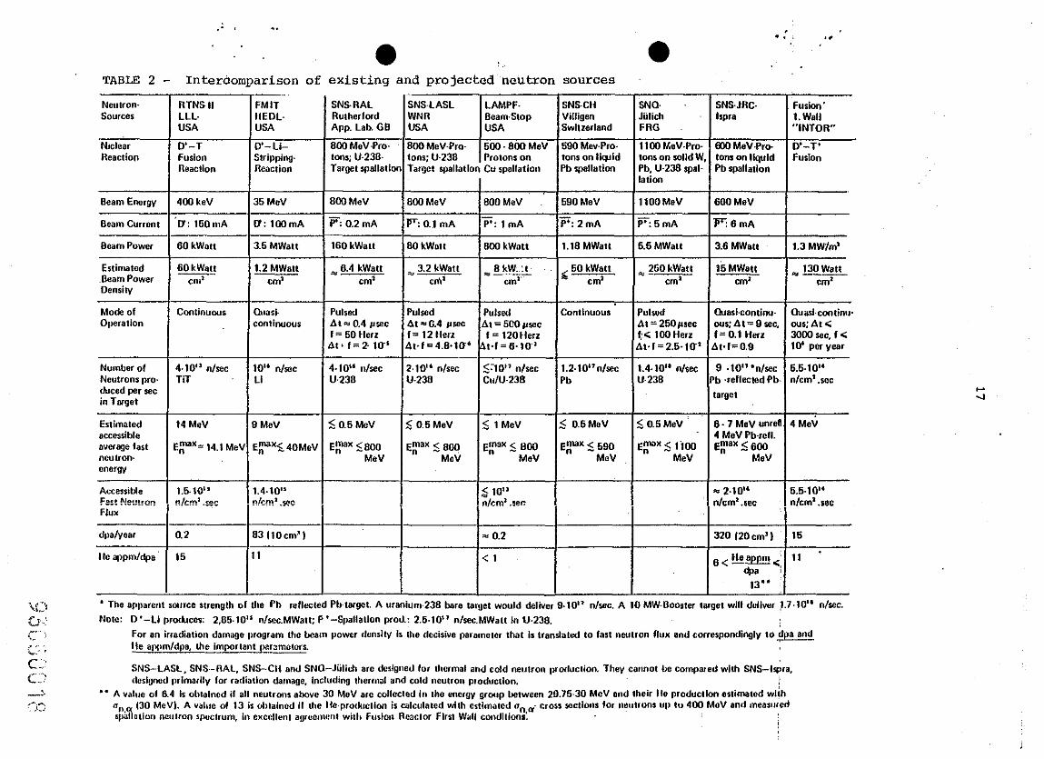
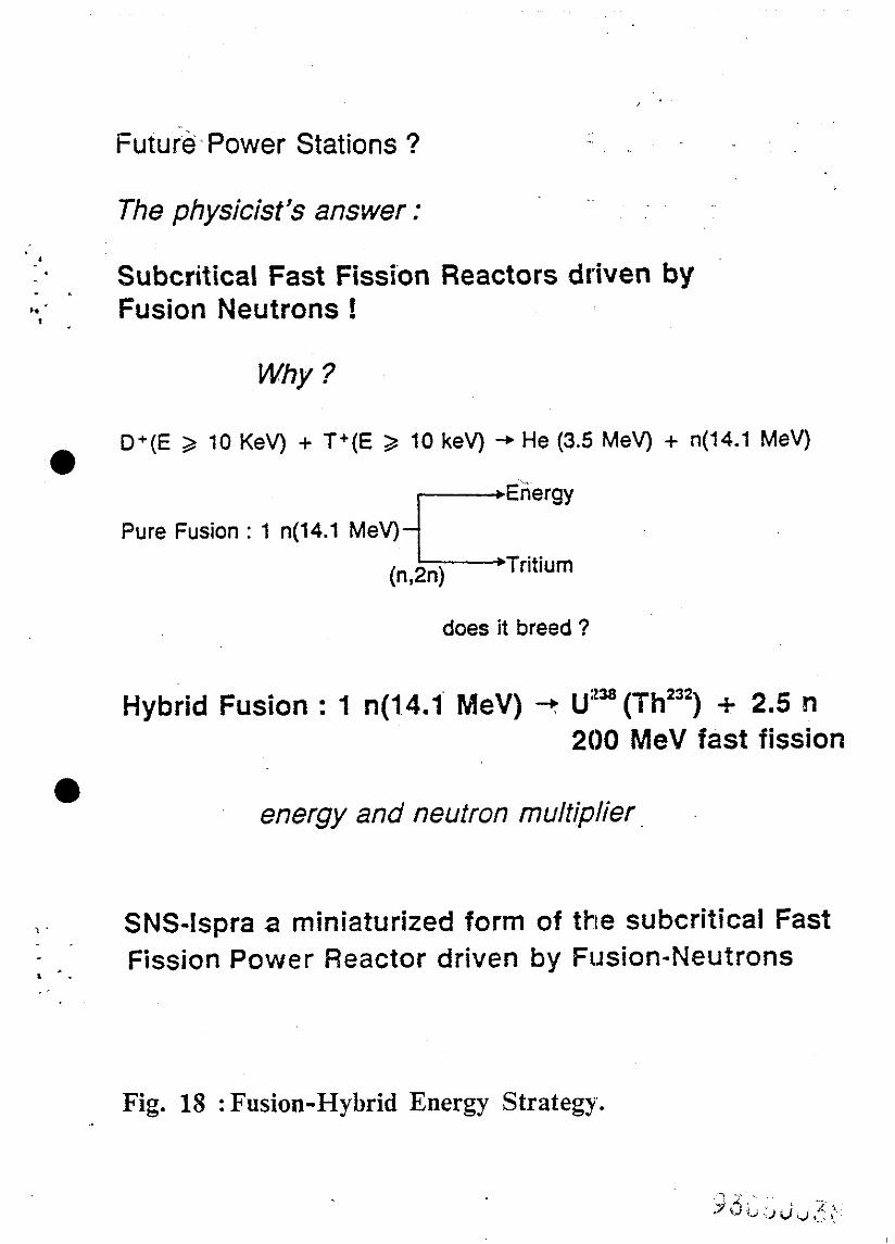
Fig. 18 gives an outlook why fusion-fission hybrid power stations
might be more economic than pure fusion reactors. The SNS-Ispra is a
miniaturised form of a fusion-fission hybrid reactor system. In Table 2
the various neutron source Darameters, of interest in our context, ars
listed.

14
v 1.
.:
’ 2.
3.
l .4.
5.
6.
a
7.
8.
9.
10.
11.
12.
13. :-
14.
1.5.
M.T. Robinson, "The energy dependewe of neutron radiation damage in solids", BNES Nuclear Fusion Reactor Conf.. at Culham Laboratory, September 1969.
DonM. ParkinandAlleaN. Goland , ?Calculation of radiation effects as a function of incident neutron spectrum", BNL-report, BNL-50434 (1974) and in: Radiation Effects, l976, Vol. 28, pp. 31-42. . .
P'. Grand, K. Batchelor, J.P. Blewett, A. Goland, D. Gurinsky, J. Kukkoneeand C.L. Snead, Jr., "An intense Li (d,n) neutron radiation test facility for controlled thermonucI.ear reactor ma- terials testing=, Nuclear Technology, Vol. 29, June 1976, pp.327- 336.
E.K. Gppe-, HEDL-TME81-45 UC-20, January 1982.
W. Reiter, B. Strohmair and M. Uhl, "Final report", on work under Euratom Contract No.1125-79-97 SISP C.
F. Atchison, W.E. Fischer and M. Pepin, "First and second interim reportsand final report" on work carried out for contract No. 2007-82-12 ED ISP, CH.
V. Herrhberger, ?. Stiller and M. Victoria, "Some es&sates of the fusion radiation damage simulation by spallation neutrons", Workshop.on Evaluation of Simulation Techniques for Radiation-, Damage in the Bulk of Fusion First Wall Materials, Interlakeu, Switzerland, June 27-30, 1983.
S. Cierjacks et al., "Messungen dex absolutes Ausbeuten . ..-. 11.04.05 012A KFK-Earlsruhe, February 1980.
W. Kley and G.R. Bishop, "The JRC-Ispra fusion reactor materials test and development facility", Nuclear Science and Technology, November 1984, EUR 9753EN.
R.A. Jameson and S.O. Schriber, private communication, May 1985.
Yu. V. Petrov, Yu. M. Shabel'skiirlSov. J. Nucl. Phys. 0 (11, (1979) 66.
L. Bracci, B. Fiorentini, "Hesic molecules and muon catalyzed fusion", Physics Report 86, No.4 (1982).
S.E. Jones, A.J. Caffrey, J.B. waiter, A.N. Anderson, S.N. Brad-' burg, P.A. Gram, M. Leon and MA. Paciotti, in: .MuOn - Catalysed Fusion Workshop, Jackson Hole, 'WY, June 7-8, 1984, EG&G IdahO Inc.
H. Takahashi and A. Moats, Atomkernenergie-Kerntechnik, Vol.43 (1983) No.3, pp.188-190.
H. Takabashi,. "Reactivation coefficient of muon catalysed D-T fusion and its enhancement", BNL-report 35543, October 1984.
L
.
.
16. Dr. Louis Rosen, Director of LAM;, private cc~mmuni.c~tion,,Nay 1985.
17. w. Khy, “Design proposal for a material science spectrometer at the SNQ Jtilich, FRG", intited contribution. to the SNQ Workshop at Maria Leach, September 3-5, 1984, Jfil-1954, ISSN 0366-0885, October 1984, KFA Jiilich, F-R-G.
1. ’ : .‘ -.
.
TABLE 1 - Neutron source performance data for 600 and 1200 MeV protons
Proton energy : 600 Mev Proton energy : 1200 MeV Sample position: Z = 3.75 cm Sample position: Z = 3.75 cm
Plux/proton (n/cm2)
0.065
En MeV
4.75
<IIt?> mbarns
9.655
Flux/proton (n/cm2)
0.069
En MeV
6.31
iHe> mbwns
15.061
Conclusion:
Switchhi from 600 to 1200 MeV protons increases:
1. (dpa.volume) by a factor 2,64
2. Peak neutron flux by 37%
3. Mean neutron energy by 33%
4. He-production density by a factor 2.13
5. Total helium production by a factor 3,5
i
.:;
. TABLE 2 - Interclomparison of existing and projected neutron sources
Ne"so~ Soureer
Nrclcar Reection
ftTNS II LLL- USA
SNSJRC. FUdOll’ lslm 1. Wall
“INTOR”
mo MeV.lh D.-T’ tom on liquid Fusion Pb rylla,lon
D’-T FUhXl RWWCllO”
I I I I D’- Li- SW M&Pro% 600 MeV-Pro- 500~ ffw Llev 590 MewPro. 1199 MeV-Pn Strlppirq tons; u23n- tons; u-230 Protons 0” tons on lipid tons on solid’ Reaction Target spatlath Target rpellatlon Cu spallation Pb rpallation Pb. U-238 spz
I lation
Beam Energy 400 keV 35MeV
0: lOOmA
3.6 MWatt
1.2 MWa,, cm’
800 Mev ml MeV SOOMeV .’ 690MeV IlOOMeV
p: 0.2 mA EClfmA P’:lmA ?+ZmA F:6mA
160 kWe,, 80 kWn,, 800 kWat, 1.18 MWatt 6.6 MWall
6.4 kWatt ii( 4 3.2 kWa,, 8 kW:,:,, cm’ CotI’ “-&F-
60 kWatt &------
260 kWatt cm’
e-e cm’
600 MWV I
Beam Current u: 160mA
Beam Power
Estimated Beam Power Denshy
60 kWa,,
GOkWa,, C”l’
15MWatt
I
g 130 Watt cm‘ cm’
Quart PUlred PUl@d Pulsed con,inuour
I Atr.O.4wec At==G.4 wet f = 60 Herz ,= 12l.lerz
At. f=2 10.‘ At~f=4.9~lU’ k
cQntlnuoul~ At=‘XOwec
f = 120 tlen I
Pulsed At = 260prec t< 1OOtlerz
,.f=F?1,J’ A,.l= 2.6.10
Quariamtin~ (luart-condnw our:At=9w, cw:At< f = 0.1 Hen
I
3009 sec. f < bt.f=O.9 lc+ per yes,
f.10” n/w TiT
IO” n/set Ll
4. IO“ ,l/seC u.23n
2.10” n/see Lt.236
s:lo” nlsec CuJU-238
1.2.lO”n/zec 1.4.10” n/se, Pb U-238
9 .lO” ‘n/s-% 6.6.10” ‘b .reflec,ed Pb-, n/cm’.acc
t*WJ*t
Number of Neutronr pro. duced per set in Torge,
I4 MeV
:p= 14.1 Me’
6.7 M*V unren 4 h4e\j 4 MeV Pb-refl. Epx < 600 --I- t&V
-s 2.10“ 6.6.10” n/cm= .rec n/cm .sec
Estimaled accerrible wETage far, “e”,ro”- energy
AceesiWe F”..N. , _” -_. ..“*2.,-.. FIUX
E
- 1
t -
1.6.10” ?hrn’ .,ec
1.4.10” “km* .s?F I I
93 IlOw’) = 0.2
‘1 <l
dpalyeer
I Ic qpmldps
1.2
I6
* The apparen, satme rlrenglh of [he Pb reflecled Pb,arge,. A uranium.239 bare targe, would deliver 9.10” nlsec. A 10 MW-Bower target wilt deliver !.7.10“ nlrcc.
Note: D’-Li pro&ccr: 2.05.10” n/sec.MWa,,; P’-Spallatlon prod.: 2.6.10” n/w.MWa,, In U.236.
For an irrediation damago fuogram the beam power demity is lhe dccirive parameler [ha, is wandated 10 far, nwlron flux and correspondingly co- Ile eppmldpa, [he impm,anLyzrsmc,crr
SNS-LASL. SNS--fIAL. SNS-CH and SNO--Jiilich we dcstwed for dwmal and cold neutron fwlxlucdon. They cannot b+ compared wl,h SNS-l&a. dertgned primarily far radialton damage. Including thermal and cold newon pmducdon. !
” A vdwe of 6.4 b obetncd if all neurons ahwe 30 MeV are coltcclad in Ihe energy group between 29.76-30 McV and [heir lie produclton estimated wiih rr,,
9 (30 t&V). A value of t3 b oloained if the Ite~produc,lon b olcela,ed wllh cr,tmv,ed o,, o1 cr,,n ICC,,DIM for ncutronr up 10 400 MuV and measured
rpal ~lion neutron ~~~~‘clrutn, il l excellml agreemeul with Furlon Rcaclar Flrr, Wall condlltonr:
.18
. .
. .*-
l
0
r
FIGURE CAPTIONS
Fig. 1. Geometry and -parameters of the theoretical program.
Fig. 2 @i-Values in SST316 as a function of sample position for an iron shielded neutron source: up = 600 MeV.
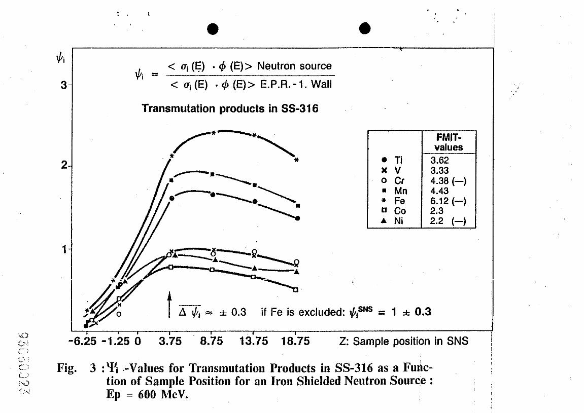
Fig. 3 $i-values for transmutation products in SS-316 as a function of sample posiqon for an iron shieLded neutron. Source: Ep = 600 mev.
Fig. 4 $i-values in SS-316 as a function of sampLe position for an iron shielded neutron source: Ep = 1200 MeV.
Fig. 5 Qi-VdUeS for tr~~~~~tati~n products in SS-316 ES a fUtX?tiOn
of sample position for an iron shielded nlsutron source: Ep = 1200 t-rev.
Fig. 6 Spectrum averaged <dpa>- and <He:dpa>-values as a function of mean neutron energy.
Fig. 7 Primary recoil energy spectra for SS-316 for neutron sources based on 600 and 1200 MeV protons, fusion first wall and MIT (perturbed).
Fig. 8 Primary recoil.*energy spectra for iron for neutron sources ba- sed on 600 MeV and 1200 HeV protons , fusion first wall and FKIT (perturbed).
Fig. 9 Neutron spectra at 3.75 cm for iron shielded neutron sources based on 600 and 1200 MeV protons.
Fig. 10 Damage efficiency in iron.
Fig. 11 The conceptional design of the liquid lead target; vertical cross section.
Fig. 12 Conceptional design of target-stztion; l/2 horizontal Cross section.
Fig. 13 Vertical cross section of conceptual SNS target station.
Fig. 14 Lay-out of the neutron target station.
Fig. 15 Lay-out of the fusion reactor m.nterials test znd development facility, based on a continuous wave 600 %V, 6 n9 proton linear accelerator.
Fig. 16 EUFZX: a European solution to future needs of neutrons.
.
. . .
19
Fig. 17 The material science spe.Ctrometer.
Fig. 18 Fusion hybrid energy strategy.
Fig. 19 'rime schedule for EXSRAC.
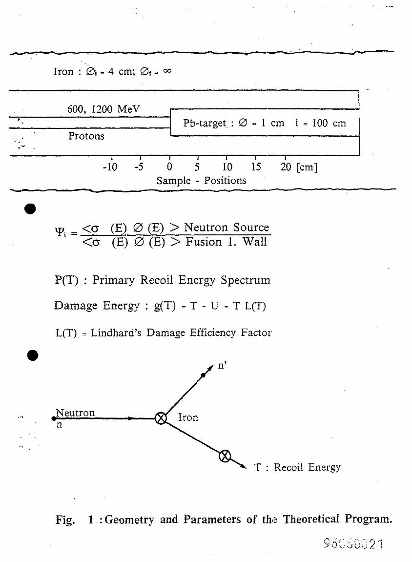
Iron :~‘isri = 4 cm; Of = co
600, 1200 MeV -T Pb-target~t : 0 = 1 cm 1 = 100 cm -
Protons ‘ ..’ .” - 1 I I I 1
-10 -5 0 5 10 15 Sample - Positions
-- -
\yi = <o (E) 0 (E) > Neutron Source <O (E) 0 (E) > Fusion 1. Wall’
P(T) : Primary Recoil Energy Spectrum.
Damage .Energy : g(T) = T - U = T L(T)
L(T) = Lindhard’s Damage Efficiency Factor
. . . Neutron n
_ .I
T : Recoil Energy
Fig. 1 : Geometry and Parameters of the Theoretical Program.
0.5
l&J oi
‘.’ . . 0
$I = < Oi (E) . 4 (E)> Neutron source
< Ui (E) 6 4 (E)> E.P.R.-1. Wall
I-7 A , = -k 0.3 i lj,NS = 1 f 0.3 . .
2.18 2.38 2.77 1.09 1.27
-6.25 -1.2 0 3.75 8.75 13.75 18.75 23.75 Sample position
Fig. 2 :‘I-( -Values in SS-316 as a Function of Sample’Yosition for an Iron Shielded Neutron Source : IQ = 600 MeV.
44
3 $7 =
< Cri (4) l 4 (E)> Neutron source
< Ui (E) - 4 (E)> E.P.R. - 1. Wall
Transmutation products in SS-316
FMlT- values
. T! 3.62 nv 3.33 0 Cr 4.36 (-) m Mn 4.43 + Fe 6.12 (-) u co A Ni z:; (-)
i / 5/O A 0.3 if Fe is excluded: tits”” = 1 f 0.3
-6.25 -6.25 -1.25 -1.25 0 0 3.75 3.75 8.75 8.75 13.75 13.75 18.75 18.75 Z: Z: Sample Sample position position in in SNS SNS 1~. .~
L’ ! c-:
C-L Fig. 3 :% .-Values for Transmutation Products in SS-316 as a Fuhc- ~ ~ :.J tion of Sample Position for an Iron Shielded Neutron Source : ,- .., A Ep = 600 MeV. ,
j /
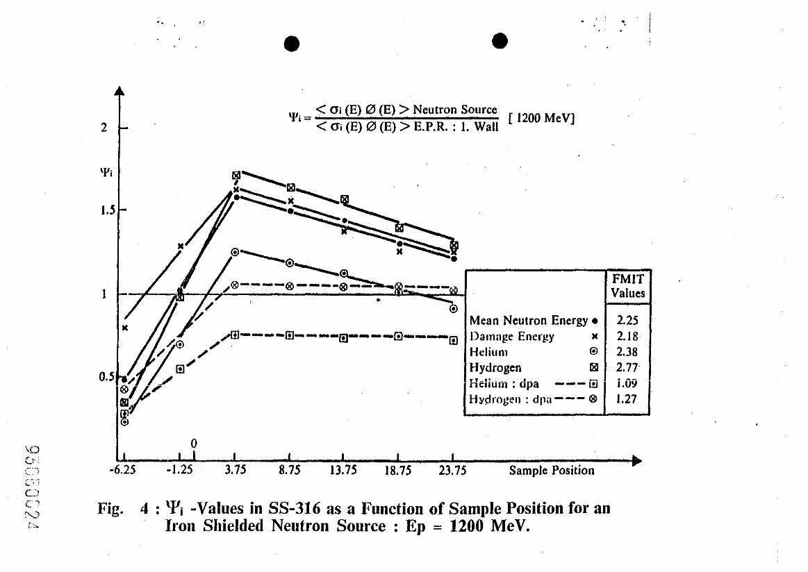
y,, = < oi (E) 0 (E) > Neutron Source ’ < (Ti (E) 0 (E) > E.P.R. : 1. Wall
[ 1200 MeV]
FMIT Values
i
2.25 2.18 2.38 2.77. . ^^ I.UY 1.27 I
0 I I I I 1 1 I -6.25 -1.25 3.75 8.75 13.75 18.75 23.75 Sample Position b
Fig. 4 : ‘Yi -Values in SS-316 as a Function of Sample Position for an Iron Shielded Neutron Source : Ep = 1200 MeV.
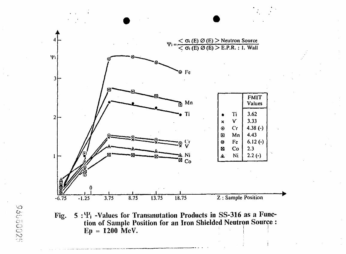
~. =,< CJi (E) 0 (Ej > Neutron Source ’ < CYi (E) 0 (E) > E.P.R. : 1. Wall
l Ti 3.62 x v 3.33 0 Cr 4.38 (-) I3 Mn 4.43 63 Fe 6.12 (-) 181 ,co 2.3 A’ Ni 2.2 (-)
FMrT Values
I I I I I I 15 -1.25 3.15 8.75 13.75 18.75 Z : Sample Position b
Fig. 5 :% -Values for Transmutation Products in SS-316 as a Ihnc- tion of Sample Position for an Iron Shielded Neutry Solbye : IQ = 1200 MeV.
,’ , . - .
I
~.,~._. __,. , . . . ,_. . - . , ^ . . . . - - . - - - . . - ,_. , . . - . - . - ^ - - - . - - - - ” _ .
: .._ [ barns,
3000
A g 2000 T7
1000
16
8
.’ J / 0
- A.. .a; -* / 4 8 12
MeV : En
~ . .
4 8 12 MeV
Fig. ~6 : Spectrum Averaged <dpa> and <He : dpa> Values as a Function of Mean Neutron Energy.
IO-
\
1 I I I
FMIT-Perturbed
T [ MeV ]
Fig. 7 :Primary Recoil Energy Spectra for SS-316 for Neutron Sour- ces Based on 600 and 1200 IMeV Protons, Fusion 1. Wall and FMIT (perturbed).

IO-:
IO'
10- l
&. 10-
:
0.5 1.0 1.5 2.0
T [ MeV ]
Fig. 8 :Primary Recoil Energy Spectra for Irorl for Neutron Sources Based on 600 MeV and 1200 lMeV Protoms, Fusion 1. Wall and FMIT (perturbed).
10’
10
.
,600 MeV q\
I I 1.0 lo.u
Neutron Energy [ MeV ]
l-7 I 100.0
1O-5 1 0.1
9 : Neutron Spectra at 3.75 cm for Iron Shielded Neutron Sowce Based on 600 and 1200 MeV Protons.
9 ,5 i; ;; a 2 ‘i\ i;~:
A U-0 g(fl = T*L(T,
0.5 - IMe\‘] ~~...... -.
L(T) : Lind hard’s Effkiency Fa.ctor g(T) = L(T)*T : Damage Eneig:y
: Primary Recoil Energy
I I I 0 10 20 30
Fig.10 Damage Deficiency in Iron
D.8
0.6
0.4
0.2
Pulsed 600 Me1
//////A Proton- Beam : 0 =5mlr At=9sec f aO.lHd
Liquid - Lead or Lead-Bismuthlnlet \
. V=lOm/sec
Fig. 11 : The Conceptional Design of the Liquid Lead Target; Vertical Cross Section.
SDallation - Neutron-Target .
Beam - Stop :
tsotop - Production
, .3cm ,
/
No - H20 or 020 For Safety
‘: i’ Fig. 12 : Conceptional Design of Target-Station; l/2-Ho&o&al ‘cross
Section. ;!
Be- Be- Reflector Reflector
Be- Reflector
Fig. 13 : Vehxl Cross Section of Conceptional SNS Target StaGon. ‘.
, ,,:
. ~ .
Proton -
Beam
l
1 / / 3
--Lit
4
Fig. ,1.4 : Lay-Out of thi Neutron Target Station.
1 : Materials-Test Zone
2: Thermal and Cold Neutron Moderators
3: Bent Neutron Guide Tubes for Analytical Materials Science Instruments
4: Iron Shield
5: lsotop Production Zone
Isotope Production
I 600 MeV, 6 mA - Proton Linear Accelerator
H-- Injector
,u Fusion
P!l Bio-Medical-Research
Fe
Target Station jfor ‘,
Physics Experiments ., : !
Fig. 15 : Lay-Out of the Fusion Reactor Materials Test and Develop- ment Facility, Based on a Continuous Wave 600 MeV; 6 qA : Proton Linear Accelerator. I : ‘, ,i :,
H+
~,
Injector
1200 MeV, 12 (24) mA Pulsed Proton Linear Accelerator H+ U-Fusion
> c!!3& &l 2% Fe Breeding
5?T 57 5? fs Incineration Bio-Medical
Pulse Frequency : 100 Pulseskec I, H- Research
Pulse Width : 250 p.sec I i4m 4 H- Injector Continuous H’
Pulse - Stretcher Neutron Irradiation Target Station
Fig. 16 : EURAC : A European Solution t6Future Needs of Neutrons ! I
. 8
- . i. *
’ ,
FutukPower Stations ?
The physicist’s answer :
Subcritical Fast Fission Reactors driven by Fusion Neutrons !
Why ?
D+(E 2 10 KeV) + T+(E 2 10 keV) + He (3.5 MeV) + n(14.1 MeV)
i_
Glergy
Pure Fusion : 1 n(14.1 MeV)
(n2n) Tritium
does it breed ?
Hybrid Fusion : 1 n(1.4.1’ MeV) ? lJzzB (l71~~~) + 2.5 ” 200 MeV fast fission
energy and neutron multiplier,
SNS-lspra a miniaturized form of thle subcritical Fast Fission Power Reactor driven by Fusion-Neutrons
Fig. 18 : Fusion-Hybrid Energy Strategy.
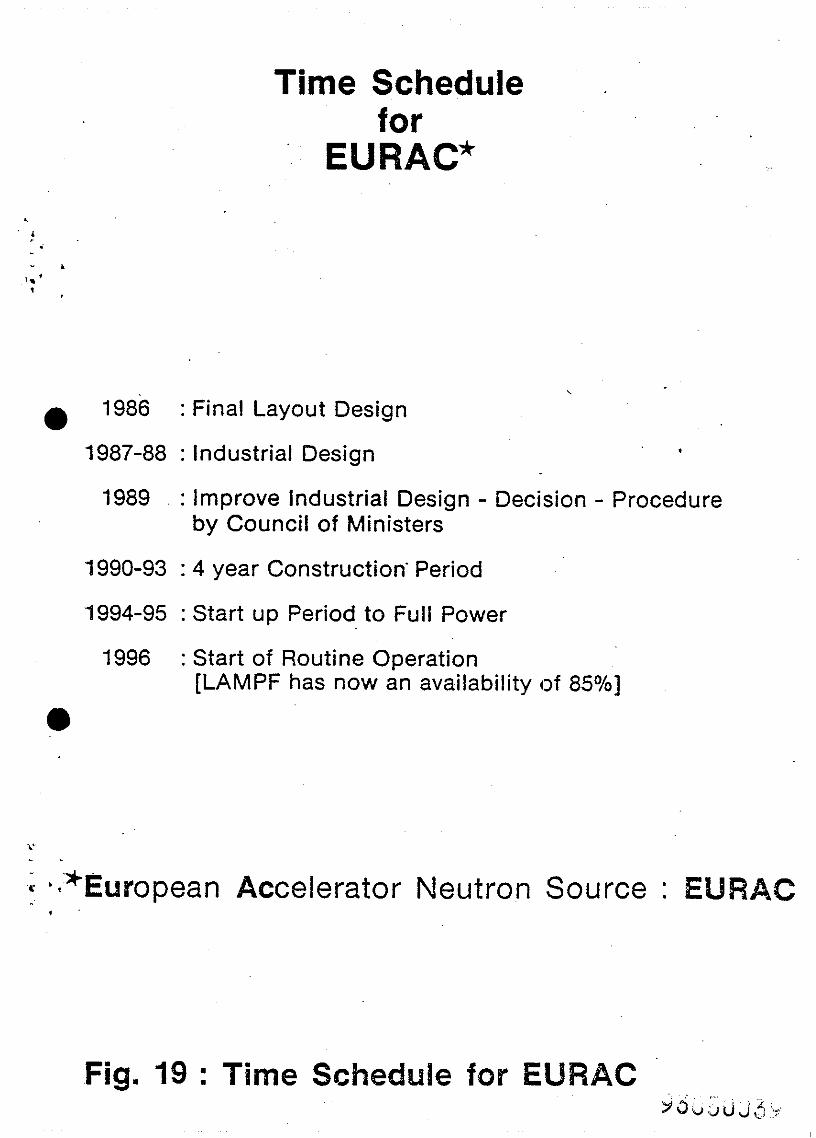
Time Schedule . for
‘~ EUWAC* . !
- L I.’ ’ .
1986 \
a : Final Layout Design
1987-88 : Industrial Design 4
1989 : Improve industrial Design - Decision - Procedure by Council of Ministers
1990-93 : 4 year Construction’ Period
~1994-95 : Start up Period to Full Power
1996 : Start of Routine Operation [LAMPF has now an availability of 85%]
a
~; b*‘*Eurropean Accelerator Neutron Source : WRAC ^’ ,