Embed Size (px)
Citation preview
EUROPEAN ORGANISATION FOR THE SAFETY OF AIR NAVIGATION
EUROCONTROL
EUROCONTROL EXPERIMENTAL CENTRE
CONTROL TOWER OPERATIONS: ROLES DESCRIPTION
EEC Note No. 09/06
Project MMF
Issued: June 2006
The information contained in this document is the property of the EUROCONTROL Agency and no part should be reproduced in any form without the Agency’s permission.
The views expressed herein do not necessarily reflect the official views or policy of the Agency.

REPORT DOCUMENTATION PAGE
Reference: EEC Note No. 09/06
Security Classification: Unclassified
Originator:
Originator (Corporate Author) Name/Location: DeepBlue s.r.l Via Basento 52/D 00198 ROMA ITALY Telephone: +39 06 85 54 801
Sponsor: Marc Bourgois Deputy Manager Innovative Research Area EUROCONTROL Experimental Centre
Sponsor (Contract Authority) Name/Location: EUROCONTROL Experimental Centre Centre de Bois des Bordes B.P.15 F – 91222 Brétigny-sur-Orge CEDEX FRANCE Telephone: +33 (0)1 69 88 75 00 WEB Site: www.eurocontrol.int
TITLE: CONTROL TOWER OPERATIONS: ROLES DESCRIPTION
Authors Monica Tavanti (DEEPBLUE)
Date 06/2006
Pages viii + 13
Figures 6
Tables 1
Annexes -
References 16
Project
MMF Task No. Sponsor
C61PT/20004 Period 2006
Distribution Statement:
(a) Controlled by: Marc Bourgois (b) Special Limitations: None
Descriptors (keywords):
Tower, Controllers’ roles, Tasks
Abstract:
This document constitutes an input to a larger project that aims to propose and evaluate Augmented Reality (AR) applications for towers. The AR project aims to provide tools that enhance the tasks carried out in the tower, which, nowadays, can be limited by a number of factors (e.g., bad visibility, areas of the airport that are occluded, etc.). In order to determine which tasks could benefit most from the AR technology, it is important to have some knowledge about the activities carried out in the tower.
This document (essentially written for students) provides a simple and short account of the towers activities, including a description of the main roles, the tools, and the phraseology deployed.

Control Tower Operations: Roles Descriptions EUROCONTROL
Project MMF – EEC Note No. 09/06 v
FOREWORD
The increasing demand for higher levels of safety and capacity require the exploration of new technologies, especially at bottlenecks in the air traffic system, such as airports.
The Augmented Reality for Tower Control project has selected a specific innovative technology (Augmented Reality), a specific ATC setting (the Control Tower), and an approach that combines the technological push with the final users’ needs and the operational constraints.
We believe that Augmented Reality (AR) could be a valuable technology to support and enhance the controller’s view-out-of-the-window. However, how can AR be applied and tailored to this specific domain?
The present note provides an account of the controllers’ roles description and attempts to support a better understanding of the current controllers’ practices. This understanding is a preliminary requirement towards the evaluation of the applicability of AR in this environment.
Marc Bourgois Deputy Manager Innovative Research Area
EUROCONTROL Control Tower Operations: Roles Descriptions
vi Project MMF - EEC Note No. 09/06
Page left intentionally blank
Control Tower Operations: Roles Descriptions EUROCONTROL
Project MMF – EEC Note No. 09/06 vii
TABLE OF CONTENTS
LIST OF FIGURES ........................................................................................................... VII
LIST OF TABLES............................................................................................................. VII
1. SUMMARY AND PURPOSES OF THE DOCUMENT...................................................1
2. CONTROL TOWER: PHASES AND AREA OF RESPONSIBILITY............................2 2.1. SOME DEFINITIONS ..................................................................................................... 2
3. GENERAL TASKS........................................................................................................4 3.1. PAPER STRIPS AND OTHER TOOLS.......................................................................... 4 3.2. TOWER CONFIGURATION........................................................................................... 5 3.3. TWR CONTROLLER...................................................................................................... 6
3.3.1. Priorities.............................................................................................................8 3.3.2. Use of Runway Holding Point and Separation Minima......................................8
3.4. HAND-OVER IN THE TOWER....................................................................................... 8 3.5. GND CONTROLLER...................................................................................................... 9
3.5.1. Priorities.............................................................................................................9 3.6. A/C POSITIONS AND CLEARANCES......................................................................... 10
4. SOME PHRASEOLOGY .............................................................................................11
5. REFERENCES............................................................................................................12
6. ACKNOWLEDGEMENTS ...........................................................................................13
LIST OF FIGURES Figure 1: CT operations (adapted after Piedra, 2000) ................................................................... 2 Figure 2: A departure flight paper strip (After Rossi & et al., 1996) ............................................... 5 Figure 3: A generic tower with main CWP (Adapted after van Ham, 2004)................................... 5 Figure 4: A TWR controller ............................................................................................................ 7 Figure 5: Holding A/C (Adapted after ICAO-4444, 2001) .............................................................. 8 Figure 6: Designated positions of A/C from an aerodrome control tower viewpoint operations
(ICAO-4444, 2001) ....................................................................................................... 10
LIST OF TABLES
Table 1: Some ATC phraseology ............................................................................................... 11
EUROCONTROL Control Tower Operations: Roles Descriptions
viii Project MMF - EEC Note No. 09/06
Page left intentionally blank
Control Tower Operations: Roles Descriptions EUROCONTROL
Project MMF - EEC Note No. 09/06
1
1. SUMMARY AND PURPOSES OF THE DOCUMENT
The present document is an input to a larger project that aims to propose and evaluate Augmented Reality (AR) tools for Control Tower. The AR project aims to provide tools that enhance the tasks carried out in the tower which, nowadays, can be limited by a number of factors, such as: bad visibility, areas of the airport that are occluded, etc.
In order determine which tasks could benefit most from the AR technology, a global understanding of the tower functioning is required.
This document provides a description concerning how a (generic) tower works, giving an account of:
1. Standard definitions
2. The general tasks
3. The tools used in the tower
4. The tower configuration
5. The main ATCOs roles and their activities
6. Some relevant phraseology
EUROCONTROL Control Tower Operations: Roles Descriptions
Project MMF - EEC Note No. 09/06
2. CONTROL TOWER: PHASES AND AREA OF RESPONSIBILITY
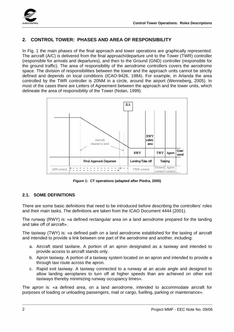
In Fig. 1 the main phases of the final approach and tower operations are graphically represented. The aircraft (A/C) is delivered from the final approach/departure unit to the Tower (TWR) controller (responsible for arrivals and departures), and then to the Ground (GND) controller (responsible for the ground traffic). The area of responsibility of the aerodrome controllers covers the aerodrome space. The division of responsibilities between the tower and the approach units cannot be strictly defined and depends on local conditions (ICAO-9426, 1984). For example, in Arlanda the area controlled by the TWR controller is 20NM in a circle, around the airport (Wenneberg, 2005). In most of the cases there are Letters of Agreement between the approach and the tower units, which delineate the area of responsibility of the Tower (Nolan, 1999).
Figure 1: CT operations (adapted after Piedra, 2000)
2.1. SOME DEFINITIONS
There are some basic definitions that need to be introduced before describing the controllers’ roles and their main tasks. The definitions are taken from the ICAO Document 4444 (2001).
The runway (RWY) is: «a defined rectangular area on a land aerodrome prepared for the landing and take off of aircraft».
The taxiway (TWY) is: «a defined path on a land aerodrome established for the taxiing of aircraft and intended to provide a link between one part of the aerodrome and another, including:
a. Aircraft stand taxilane. A portion of an apron designated as a taxiway and intended to provide access to aircraft stands only.
b. Apron taxiway. A portion of a taxiway system located on an apron and intended to provide a through taxi route across the apron.
c. Rapid exit taxiway. A taxiway connected to a runway at an acute angle and designed to allow landing aeroplanes to turn off at higher speeds than are achieved on other exit taxiways thereby minimizing runway occupancy times».
The apron is: «a defined area, on a land aerodrome, intended to accommodate aircraft for purposes of loading or unloading passengers, mail or cargo, fuelling, parking or maintenance».
2
Control Tower Operations: Roles Descriptions EUROCONTROL
Project MMF - EEC Note No. 09/06
3
The runway holding position is: «a designated position intended to protect a runway, an obstacle limitation surface, or an ILS/MLS critical/ sensitive area at which taxiing aircraft and vehicles shall stop and hold, unless otherwise authorized by the aerodrome control tower».
The Instrument Landing system (ILS) is a ground-based radio system (usually located near the RWY) that provides guidance to the aircraft during the landing, by providing lateral and vertical guidance, including indications of distance from the optimum point of landing (FAA Glossary).
The Microwave Landing System (MLS) is a system similar to the ILS, in that it provides the guidance for exact alignment of a landing A/C. However, the MLS uses a more robust technology, which allows greater flexibility. In fact, with the MLS it won’t be necessary to require all aircraft to go to a common point to start their approach to land (ICAO-9426, 1984).
The Standard Instrument Arrival (STAR) is a flight rule arrival route, linking a significant point on a route with a point from which the approach procedure can be commenced.
The Standard Instrument Departure (SID) is a flight rule departure route, which links the aerodrome (or a specified runway) to a significant point, at which the en-route phase of a flight begins.
There is a distinction between the definitions “Visual Flight Rules” (VFR) and “Instrument Flight Rules” (IFR). VFR refers to the rules that govern the procedures for conducting a flight under Visual Meteorological Conditions (or VMC, which are defined as: «meteorological conditions expressed in terms of visibility, distance from cloud, and ceiling1, equal or better than specified minima»2). IFR refers to the rules that govern the procedures for conducting a flight under Instrument Meteorological Conditions (or IMC, which are defined as: ««meteorological conditions expressed in terms of visibility, distance from cloud, and ceiling, less than the minima specified for visual meteorological conditions»).
Nowadays, in big commercial airports, almost everybody flies with IFR rules, independently from weather and visibility. Even if VFR flights can request the assistance of the aerodrome controllers, their number is usually very limited (Wenneberg, 2005).
1 The ceiling is defined as the: «Height above the ground or water of the base of the lowest layer of cloud below 6000 m (20000 ft) covering more than half of the sky» (ICAO-ANNEX 2, 1990). 2 A rougher -but easier to understand- explanation of VMC is that VMC implies good weather and optimal visibility.
EUROCONTROL Control Tower Operations: Roles Descriptions
Project MMF - EEC Note No. 09/06
4
3. GENERAL TASKS
As defined in (ICAO-4444, 2001) «the aerodrome controllers shall issue information and clearances to aircraft under their control to achieve a safe, orderly and expeditious flow of the air traffic on and in the vicinity of an aerodrome with the object of preventing collision(s) between:
a. aircraft flying within the designated area of responsibility of the control tower, including the aerodrome traffic circuits;
b. aircraft operating on the manoeuvring area; c. aircraft landing and taking off; d. aircraft and vehicles operating on the manoeuvring area; e. aircraft on the manoeuvring area and obstructions on that area»
The manoeuvring area is defined in (ICAO-4444, 2001) as: «that part of an aerodrome to be used for take-off, landing and taxiing of aircraft, excluding aprons». Thus, the manoeuvring area is different from the so-called movement area, which includes also the aprons. This distinction is not trivial because it circumscribes the responsibilities of the controllers. For instance, only the manoeuvring area is dependent on the controllers’ monitoring and guidance. According to Bergé (Bergé, 2005), the surveillance service should cover aircraft in the apron area, since the controllers need to know the aircraft position with regards to the future conflict on the manoeuvring area; but there is no responsibility from the controllers’ side for what is taking place on the apron. This fact is further stressed in (ICAO-4444, 2001): «Aerodrome controllers shall maintain a continuous watch on all flight operations on and in the vicinity of an aerodrome as well as vehicles and personnel on the manoeuvring area». Interestingly, the last part of the sentence states that: «Watch shall be maintained by visual observation, augmented in low visibility conditions by radar, when available».
3.1. PAPER STRIPS AND OTHER TOOLS
An important tool used by controllers is the flight strip. The flight strips: «constitute a highly flexible means of planning departure sequences and can be written on, re-ordered and otherwise physically manipulated in this process» (Fields, Amaldi, & Tassi, 2003); for instance, the strips are also called Flight Progress Strips (they are, in a manner, “alive” tools).
The strips are placed on a strip board and their order reflects the order of the traffic sequence. «The ordered sequence of flight strips indicates how the current traffic situation is organised [...]. The strip board is interesting as it provides a picture of the situation at hand, a plan of the traffic evolution and the associated estimate of the controlled workload, and a memory of activity» (Marti, 2000). In some cases (e.g. in Fiumicino Airport) the strips of arrivals and departures are color-coded.
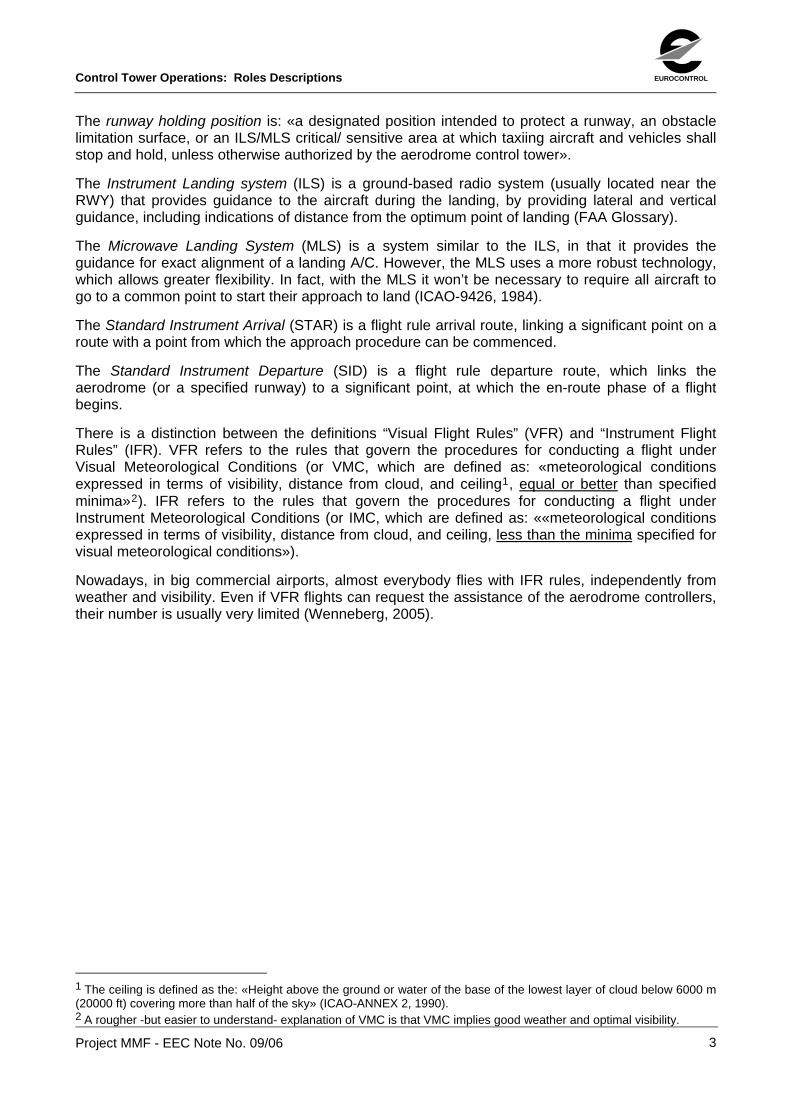
An example of a paper strip is given in Fig. 2. Every part of the paper strip carries a specific piece of information about the A/C (e.g. the A/C callsign, the time slot, the A/C type, gate number, etc.). Moreover, the strip «is a shared note pad conveying to the members of the team what actions have been taken with respect to particular aircraft» (Bentley, Hughes, Randall, Rodden, Sawyer, Shapiro & Sommerville, 1992). The strip of an A/C is “physically passed” between controllers; in the tower, this physical transfer marks the transfer of control from one controller to another.
Control Tower Operations: Roles Descriptions EUROCONTROL
Project MMF - EEC Note No. 09/06
Figure 2: A departure flight paper strip (After Rossi & et al., 1996)
There are other tools available for the aerodrome controllers, (which may vary from tower to tower), like the Ground Movement Radar, displaying the aircraft movements on the ground; a separated Radar for the landing traffic (available for the TWR controller); a Flight Data Processing (FDP) system (displaying the data concerning each flight, such as, the callsign, the type of A/C, the time slot, the assigned RWY, the route, etc.); an interface supporting the management of the lighting system; a dedicated display with weather information; and the telephone3.
3.2. TOWER CONFIGURATION
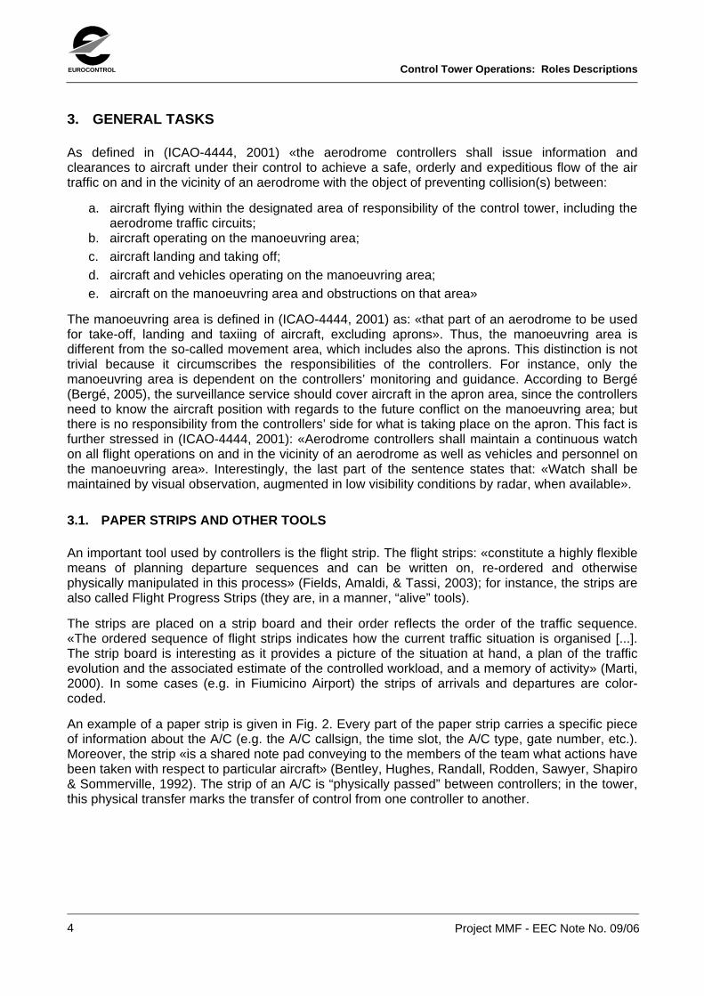
In almost every tower there are some basic Controller Working Positions (CWP): a TWR controller, a GND controller, a Flight Data Assistant (FDA), a Clearance Delivery (CD), and a Supervisor4 (cf. Fig. 3). Usually, the Flight Data assistant and the Clearance Delivery are not considered as actual controlling positions, as the TWR and the GND are.
Figure 3: A generic tower with main CWP (Adapted after van Ham, 2004)
3 As a reminder: the communication with pilots is kept via radio, one of the tools of the tower equipment. 4 This configuration is artificial. Usually, in commercial airports, within a single tower, there are several positions for each role (e.g. 2 TWR, 3 GND, etc.).
5
EUROCONTROL Control Tower Operations: Roles Descriptions
Project MMF - EEC Note No. 09/06
6
However, the role of the Clearance Delivery position is defined in (ICAO-4444, 2001) as being: «normally responsible for delivery of start-up and ATC clearances to departing IFR flights». For example, in Arlanda, the CD is in charge of giving to the A/C the permission to start-up (van Ham, 2004), the departure clearances (information like, the assigned RWY, the departure route, etc.) and makes sure that the pilot records the information provided. The same tasks are performed by the CD in Fiumicino.
In some cases, the permission to start-up is provided by the Delivery/Ground Movement Planner, who allows the start-up after s/he “has checked all constraints necessary to prevent excessive congestion will be met” (Competition Commission, 1990). In this sense, this controller performs a sort of “planning task”, supporting the GND during peak periods (Eurocontrol, 2005).
The FDA is a less “standardized” role. For instance, in Arlanda, s/he is charge of printing the strips and providing them to the appropriate controller5 (Wenneberg, 2005). In Fiumicino (where the position is called “Flight Plan Assistant”) the FDA’s main tasks are recording weather information every half hour, updating information about the flight plans, preparing the strips for the forthcoming flights and providing them to the CD (Rossi et al., 1996).
The supervisor supervises the operational team and the equipment. S/he takes decisions in case of special events and keeps the communications with the airlines, the airport services, and the approach unit. S/he is consulted for issues concerning the RWYs (Wenneberg, 2005) and is in charge of the tower configuration (i.e. merging or splitting the functions).
Additional roles can also be found in the tower, as an example the arrival coordinator (a role that is present in Fiumicino, for instance). This controller’s main task is: “to co-ordinate arrivals according to the decisions of the Approach Control Unit […]. Decisions concern the arrivals sequence, the choice of arrival routes (runway and direction) and possibly changes in the flight plan (for instance: destination change or landing delay)” (Rossi et al., 1996). The arrival coordinator, then, acts as a “communication bridge” between the TWR and the approach.
3.3. TWR CONTROLLER
This position is defined in (ICAO-4444, 2001) as being: «normally responsible for the operations on the runway and aircraft flying within the area of responsibility of the aerodrome control tower». In brief, the first responsibility of the TWR controller is to ensure that sufficient runway separation is kept between landing and departing aircraft (Nolan, 1999). Specifically, the TWR controller is responsible of: 1) the landing A/C until the RWY is vacated; 2) the departing A/C, from the holding position for the take off, until the A/C is handed off to the approach unit.
The TWR is the first contact point for the arriving traffic, right after the approach unit. The TWR issues the “clear to land” instruction (or “clear to take off”, for departing traffic) and gives to the pilot information about the weather and wind conditions. The TWR has to be aware of the conditions and of the status of all RWYs. The RWY occupancy status is checked through direct observation and radar display. The weather information is usually provided in a dedicated monitor (displaying visibility, temperature, wind direction, wind intensity, pressure). Once a departing A/C has left the area of responsibility of the aerodrome, the TWR hands over (i.e. transfers the control of) the A/C to the approach unit.
5 Sometimes, because of logistic limitations, the controllers have problems in delivering a strip to the colleagues. In Arlanda, the controllers have to walk around the tower while being connected to the desk by means of head-set cables, which hinder their movements and cause problems (van Ham, 2004).
Control Tower Operations: Roles Descriptions EUROCONTROL
Project MMF - EEC Note No. 09/06
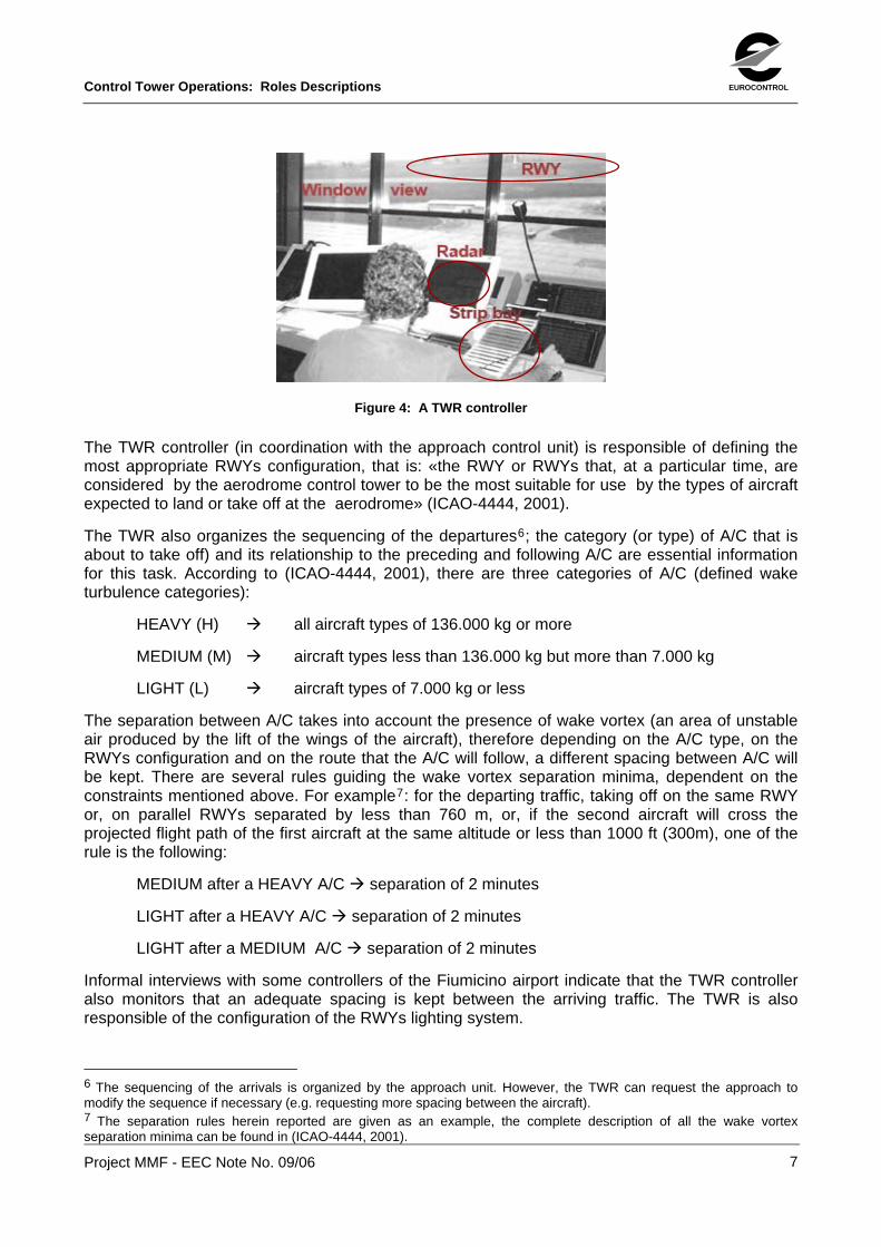
Figure 4: A TWR controller
The TWR controller (in coordination with the approach control unit) is responsible of defining the most appropriate RWYs configuration, that is: «the RWY or RWYs that, at a particular time, are considered by the aerodrome control tower to be the most suitable for use by the types of aircraft expected to land or take off at the aerodrome» (ICAO-4444, 2001).
The TWR also organizes the sequencing of the departures6; the category (or type) of A/C that is about to take off) and its relationship to the preceding and following A/C are essential information for this task. According to (ICAO-4444, 2001), there are three categories of A/C (defined wake turbulence categories):
HEAVY (H) all aircraft types of 136.000 kg or more
MEDIUM (M) aircraft types less than 136.000 kg but more than 7.000 kg
LIGHT (L) aircraft types of 7.000 kg or less
The separation between A/C takes into account the presence of wake vortex (an area of unstable air produced by the lift of the wings of the aircraft), therefore depending on the A/C type, on the RWYs configuration and on the route that the A/C will follow, a different spacing between A/C will be kept. There are several rules guiding the wake vortex separation minima, dependent on the constraints mentioned above. For example7: for the departing traffic, taking off on the same RWY or, on parallel RWYs separated by less than 760 m, or, if the second aircraft will cross the projected flight path of the first aircraft at the same altitude or less than 1000 ft (300m), one of the rule is the following:
MEDIUM after a HEAVY A/C separation of 2 minutes
LIGHT after a HEAVY A/C separation of 2 minutes
LIGHT after a MEDIUM A/C separation of 2 minutes
Informal interviews with some controllers of the Fiumicino airport indicate that the TWR controller also monitors that an adequate spacing is kept between the arriving traffic. The TWR is also responsible of the configuration of the RWYs lighting system.
6 The sequencing of the arrivals is organized by the approach unit. However, the TWR can request the approach to modify the sequence if necessary (e.g. requesting more spacing between the aircraft). 7 The separation rules herein reported are given as an example, the complete description of all the wake vortex separation minima can be found in (ICAO-4444, 2001).
7
EUROCONTROL Control Tower Operations: Roles Descriptions
Project MMF - EEC Note No. 09/06
3.3.1. Priorities
An aircraft landing, or in the final phases of an approach to land, has the priority over a departing aircraft.
3.3.2. Use of Runway Holding Point and Separation Minima
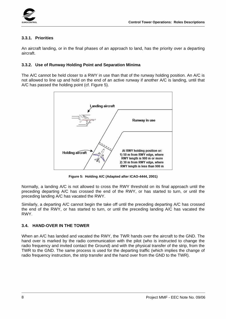
The A/C cannot be held closer to a RWY in use than that of the runway holding position. An A/C is not allowed to line up and hold on the end of an active runway if another A/C is landing, until that A/C has passed the holding point (cf. Figure 5).
Figure 5: Holding A/C (Adapted after ICAO-4444, 2001)
Normally, a landing A/C is not allowed to cross the RWY threshold on its final approach until the preceding departing A/C has crossed the end of the RWY, or has started to turn, or until the preceding landing A/C has vacated the RWY.
Similarly, a departing A/C cannot begin the take off until the preceding departing A/C has crossed the end of the RWY, or has started to turn, or until the preceding landing A/C has vacated the RWY.
3.4. HAND-OVER IN THE TOWER
When an A/C has landed and vacated the RWY, the TWR hands over the aircraft to the GND. The hand over is marked by the radio communication with the pilot (who is instructed to change the radio frequency and invited contact the Ground) and with the physical transfer of the strip, from the TWR to the GND. The same process is used for the departing traffic (which implies the change of radio frequency instruction, the strip transfer and the hand over from the GND to the TWR).
8
Control Tower Operations: Roles Descriptions EUROCONTROL
Project MMF - EEC Note No. 09/06
9
3.5. GND CONTROLLER
This position is defined in (ICAO-4444, 2001) as being: «normally responsible for traffic on the manoeuvring area with the exception of runways». In other words, the GND is responsible for the safety of aircraft that are taxing on TWYs, from and/or to the RWY (Nolan, 1999).
The pilot contacts the GND for the push-back/taxi clearance, and (after the GND’s approval) the A/C will be routed through the manoeuvring area until it has reached a holding point close to the RWY (then, the A/C will be handed over to the TWR).
The GND monitors and guide all the surface movements, is in charge of communicating to the pilots the taxi routes so as to avoid collisions with other A/C or objects, and minimizing the risk for the A/C entering an active RWY. The GND assigns priority to A/C (both arriving and departing) for the TWY occupancy.
The GND has several means to determine the position of the A/C within the manoeuvring area: 1) direct observation; 2) the ground radar; 3) the radio communications, as the controller can request to the cockpit to report and communicate the exact A/C position.
The GND may authorize an A/C to taxi an active RWY. This maneuver has to be coordinated with and approved by the TWR.
3.5.1. Priorities
The basic rule defining the sequence of departing A/C is “first come, first served”, that is: «departures shall normally be cleared in the order in which they are ready to take off» (ICAO-4444, 2001). This simple rule can be amended and the following factors can be considered when a sequence is established: «types of A/C and their relative performance; routes to be followed after take off; any specified minimum departure interval between take offs; need to apply wake turbulence separation minima; aircraft which should be afforded priority» (ICAO-4444, 2001).
As a matter of fact, the GND can decide about the departures sequence in accordance to slot constraints and/or could assign priorities so as to provide to the TWR a “smart” sequence (Wenneberg, 2005).
EUROCONTROL Control Tower Operations: Roles Descriptions
Project MMF - EEC Note No. 09/06
3.6. A/C POSITIONS AND CLEARANCES
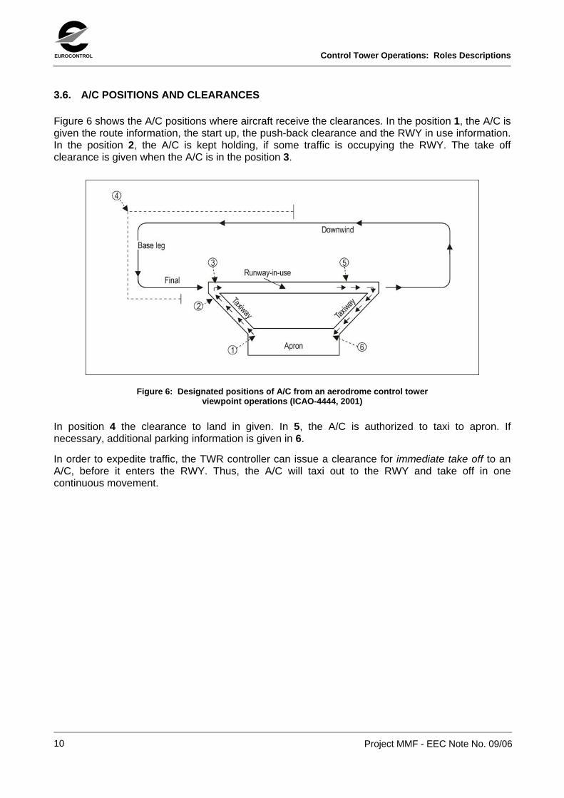
Figure 6 shows the A/C positions where aircraft receive the clearances. In the position 1, the A/C is given the route information, the start up, the push-back clearance and the RWY in use information. In the position 2, the A/C is kept holding, if some traffic is occupying the RWY. The take off clearance is given when the A/C is in the position 3.
Figure 6: Designated positions of A/C from an aerodrome control tower viewpoint operations (ICAO-4444, 2001)
In position 4 the clearance to land in given. In 5, the A/C is authorized to taxi to apron. If necessary, additional parking information is given in 6.
In order to expedite traffic, the TWR controller can issue a clearance for immediate take off to an A/C, before it enters the RWY. Thus, the A/C will taxi out to the RWY and take off in one continuous movement.
10
Control Tower Operations: Roles Descriptions EUROCONTROL
Project MMF - EEC Note No. 09/06
11
4. SOME PHRASEOLOGY
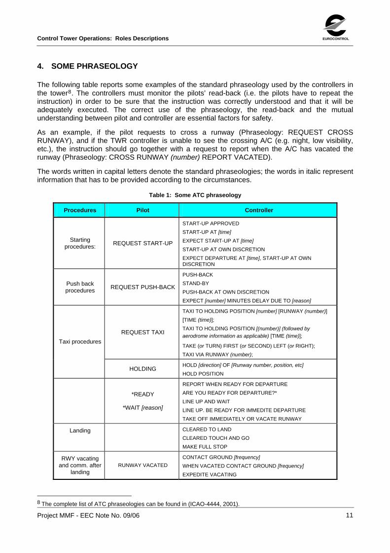
The following table reports some examples of the standard phraseology used by the controllers in the tower8. The controllers must monitor the pilots’ read-back (i.e. the pilots have to repeat the instruction) in order to be sure that the instruction was correctly understood and that it will be adequately executed. The correct use of the phraseology, the read-back and the mutual understanding between pilot and controller are essential factors for safety.
As an example, if the pilot requests to cross a runway (Phraseology: REQUEST CROSS RUNWAY), and if the TWR controller is unable to see the crossing A/C (e.g. night, low visibility, etc.), the instruction should go together with a request to report when the A/C has vacated the runway (Phraseology: CROSS RUNWAY (number) REPORT VACATED).
The words written in capital letters denote the standard phraseologies; the words in italic represent information that has to be provided according to the circumstances.
Table 1: Some ATC phraseology
Procedures Pilot Controller
Starting procedures: REQUEST START-UP
START-UP APPROVED START-UP AT [time] EXPECT START-UP AT [time] START-UP AT OWN DISCRETION EXPECT DEPARTURE AT [time], START-UP AT OWN DISCRETION
Push back procedures REQUEST PUSH-BACK
PUSH-BACK STAND-BY PUSH-BACK AT OWN DISCRETION EXPECT [number] MINUTES DELAY DUE TO [reason]
REQUEST TAXI
TAXI TO HOLDING POSITION [number] [RUNWAY (number)] [TIME (time)]; TAXI TO HOLDING POSITION [(number)] (followed by aerodrome information as applicable) [TIME (time)];
TAKE (or TURN) FIRST (or SECOND) LEFT (or RIGHT); TAXI VIA RUNWAY (number);
Taxi procedures
HOLDINGHOLD [direction] OF [Runway number, position, etc]
HOLD POSITION
*READY
*WAIT [reason]
REPORT WHEN READY FOR DEPARTURE ARE YOU READY FOR DEPARTURE?* LINE UP AND WAIT LINE UP. BE READY FOR IMMEDITE DEPARTURE TAKE OFF IMMEDIATELY OR VACATE RUNWAY
Landing
CLEARED TO LAND CLEARED TOUCH AND GO MAKE FULL STOP
RWY vacating and comm. after
landingRUNWAY VACATED
CONTACT GROUND [frequency] WHEN VACATED CONTACT GROUND [frequency]
EXPEDITE VACATING
8 The complete list of ATC phraseologies can be found in (ICAO-4444, 2001).
EUROCONTROL Control Tower Operations: Roles Descriptions
Project MMF - EEC Note No. 09/06
12
5. REFERENCES
1. Bentley, R., Hughes, J. A, Randall, D., Rodden, T., Sawyer, P., Shapiro, D., Sommerville, I., (1992). Ethnographically-informed systems design for air traffic control, Proceedings of the CSCW 1992, ACM Press.
2. Bergé, P., (2005). Initial EMMA Air-Ground Operational Service and Environmental Description (OSED Initial), Document No. D1.3.1, Eurocontrol.
3. Competition Commission, (1990). Civil Aviation Authority: A report of an inquiry into the supply of navigation and air traffic control services to civil aircraft, available at: http://www.competition-commission.org.uk
4. EUROCONTROL ATM Training Unit (2005). The ATCO Role in Airside Capacity and ATS awareness, Training Documentation APT-ACE, IANS, Eurocontrol.
5. FAA Glossary, available at: http://www.gps.tc.faa.gov/glossary.html
6. Fields, B., Amaldi, P., Tassi, A., (2003). Representing collaborative work: The Airport as Common Information Space, Technical Report IDC-TR-2003-003.
7. Gahr, S., (2003). Manuale Controllori Ground e Tower, FPI.
8. ICAO Document 4444 ATM/501 (2001). Procedures for Air Navigation Service - Air Traffic Management (PANS-ATM), International Civil Aviation Organization.
9. ICAO ANNEX 2 (1990). Rules Of The Air, Ninth Edition, International Civil Aviation Organization.
10. ICAO Document 9426-AN/924 (1984). Air Traffic Services Planning Manual, First Edition, International Civil Aviation Organization.
11. Marti, P., (2000). The choice of the unit of analysis for modellinsettings", Journal of Cognition, Technology and Work, 2:62-74.
12. Nolan, M. S., (1999). Fundamentals of Air Traffic Control (3rd ed), Florence, KY: Brooks/Cole Publishing.
13. Piedra, R., (2000). Integrated Airport control tower (IACT), results of the cross project collaborative study, Deliverable 3.3.1, Part B, Telematics Application Programme-Transport Sector, Converge Project TR 1101, available at: http://www.cordis.lu/telematics/tap_transport/library/converge_d3.3.1-2.html
14. Rossi, M., Gonnord, C., Paul, S., Darche, N., Mariano, P., Paggio, R., Ferreira, F., Adami, S., D’Aloia, P., Hesselink, H., Moyaux, J., Naves, P., (1996). MANTEA Domain Models, WP3, MANTEA/ALE-TEC-D3.2-014-R4, TR 1036, Telematics Application Programme, (Transport/Air).
15. Van Ham, S. A., (2004). Task analysis, subjective workload and experienced frequencies of unwantyed incidents in airport control tower, Report Department of Psychology, Lund University, June 2004.
16. Wenneberg, A., (2005). Personal communication.
Control Tower Operations: Roles Descriptions EUROCONTROL
Project MMF - EEC Note No. 09/06
13
6. ACKNOWLEDGEMENTS
Thanks Marc Bourgois, Patrizia Marti and Ray Dowdall for providing comments and suggestions on this report.