Embed Size (px)
Citation preview

New
pre
sent
atio
n -
see
His
tory
box
EUROPEAN ETS 300 075
TELECOMMUNICATION February 1994
STANDARD Second Edition
Source: ETSI TC-TE Reference: RE/TE-01041
ICS: 33.040.40
Key words: Processable data, file transfer
Terminal Equipment (TE);Processable data
File transfer
ETSIEuropean Telecommunications Standards Institute
ETSI Secretariat
Postal address: F-06921 Sophia Antipolis CEDEX - FRANCEOffice address: 650 Route des Lucioles - Sophia Antipolis - Valbonne - FRANCEX.400: c=fr, a=atlas, p=etsi, s=secretariat - Internet: [email protected]
Tel.: +33 92 94 42 00 - Fax: +33 93 65 47 16
Copyright Notification: No part may be reproduced except as authorized by written permission. The copyright and theforegoing restriction extend to reproduction in all media.
© European Telecommunications Standards Institute 1994. All rights reserved.

Page 2ETS 300 075: February 1994
Whilst every care has been taken in the preparation and publication of this document, errors in content,typographical or otherwise, may occur. If you have comments concerning its accuracy, please write to"ETSI Editing and Committee Support Dept." at the address shown on the title page.
Page 3ETS 300 075: February 1994
Contents
Foreword .....................................................................................................................................................13
1 Scope ................................................................................................................................................15
2 Normative references........................................................................................................................15
3 Definitions and abbreviations ............................................................................................................153.1 Definitions ..........................................................................................................................153.2 Abbreviations .....................................................................................................................16
4 Service, applications, protocols, coding ............................................................................................174.1 Service definition................................................................................................................19
4.1.1 Scope and field of application .......................................................................194.1.2 Model of the T-service...................................................................................19
4.1.2.1 Services references.............................................................194.1.2.2 Services definitions..............................................................194.1.2.2.1 General terms......................................................................194.1.2.2.2 Regimes ..............................................................................194.1.2.2.3 Roles....................................................................................204.1.2.2.4 Local concepts.....................................................................204.1.2.3 Service elements .................................................................214.1.2.3.1 General organisation ...........................................................214.1.2.3.2 Association regime ..............................................................224.1.2.3.3 Access regime .....................................................................224.1.2.3.4 Transfer regime ...................................................................234.1.2.3.5 Restrictions on the use of services......................................234.1.2.4 Concepts related to mass transfer ......................................234.1.2.4.1 Recovery during a mass transfer.........................................234.1.2.4.2 Recovery outside a mass transfer .......................................244.1.2.4.3 Anticipation window .............................................................24
4.1.3 Association regime control ............................................................................244.1.3.1 Association establishment ...................................................254.1.3.1.1 Function ...............................................................................254.1.3.1.2 Parameters ..........................................................................254.1.3.1.2.1 Service class........................................................................254.1.3.1.2.2 Called address.....................................................................264.1.3.1.2.3 Calling address ....................................................................264.1.3.1.2.4 Application name .................................................................264.1.3.1.2.5 Explicit confirmation.............................................................264.1.3.1.2.6 Timeouts..............................................................................264.1.3.1.2.7 Request identification ..........................................................264.1.3.1.2.8 Identification.........................................................................264.1.3.1.2.9 User data .............................................................................274.1.3.1.2.10 Result...................................................................................274.1.3.1.3 Association establishment operation ...................................274.1.3.2 Association release..............................................................284.1.3.2.1 Function ...............................................................................284.1.3.2.2 Parameters ..........................................................................284.1.3.2.2.1 User data .............................................................................284.1.3.2.2.2 Result...................................................................................284.1.3.2.3 Association release operation..............................................284.1.3.3 Association abort .................................................................284.1.3.3.1 Function ...............................................................................284.1.3.3.2 Parameters ..........................................................................294.1.3.3.3 Association abort operation .................................................29
4.1.4 Access regime control ...................................................................................294.1.4.1 Access establishment..........................................................30
Page 4ETS 300 075: February 1994
4.1.4.1.1 Function .............................................................................. 304.1.4.1.2 Parameters ......................................................................... 304.1.4.1.2.1 Role..................................................................................... 304.1.4.1.2.2 Function .............................................................................. 304.1.4.1.2.3 Size of transfer units ........................................................... 304.1.4.1.2.4 Anticipation window............................................................. 314.1.4.1.2.5 Recovery ............................................................................. 314.1.4.1.2.6 Transfer mode..................................................................... 314.1.4.1.2.7 User data............................................................................. 314.1.4.1.2.8 Result .................................................................................. 314.1.4.2 End of Access service......................................................... 324.1.4.2.1 Function .............................................................................. 324.1.4.2.2 Parameters ......................................................................... 324.1.4.2.2.1 User data............................................................................. 324.1.4.2.2.2 Result .................................................................................. 324.1.4.3 File directory service ........................................................... 324.1.4.3.1 Function .............................................................................. 324.1.4.3.2 Parameters ......................................................................... 324.1.4.3.2.1 Designation ......................................................................... 334.1.4.3.2.2 User data............................................................................. 334.1.4.3.2.3 Result .................................................................................. 334.1.4.4 Load service........................................................................ 334.1.4.4.1 Function .............................................................................. 334.1.4.4.2 Parameters ......................................................................... 334.1.4.4.2.1 Recovery point .................................................................... 334.1.4.4.2.2 Designation ......................................................................... 344.1.4.4.2.3 User data............................................................................. 344.1.4.4.2.4 Result .................................................................................. 344.1.4.5 Save service........................................................................ 344.1.4.5.1 Function .............................................................................. 344.1.4.5.2 Parameters ......................................................................... 344.1.4.5.2.1 Recovery point .................................................................... 354.1.4.5.2.2 Designation ......................................................................... 354.1.4.5.2.3 User data............................................................................. 354.1.4.5.2.4 Result .................................................................................. 354.1.4.6 Rename service .................................................................. 354.1.4.6.1 Function .............................................................................. 354.1.4.6.2 Parameters ......................................................................... 354.1.4.6.2.1 New name........................................................................... 364.1.4.6.2.2 Designation ......................................................................... 364.1.4.6.2.3 User data............................................................................. 364.1.4.6.2.4 Result .................................................................................. 364.1.4.7 Delete service ..................................................................... 364.1.4.7.1 Function .............................................................................. 364.1.4.7.2 Parameters ......................................................................... 364.1.4.7.2.1 Designation ......................................................................... 364.1.4.7.2.2 User data............................................................................. 364.1.4.7.2.3 Result .................................................................................. 374.1.4.8 Typed data service.............................................................. 374.1.4.8.1 Function .............................................................................. 374.1.4.8.2 Parameters ......................................................................... 374.1.4.8.2.1 User data............................................................................. 37
4.1.5 Transfer regime control ................................................................................ 374.1.5.1 Mass transfer ...................................................................... 384.1.5.1.1 Function .............................................................................. 384.1.5.1.2 Parameters for T-WRITE.................................................... 384.1.5.1.2.1 Explicit confirmation ............................................................ 384.1.5.1.2.2 First block............................................................................ 384.1.5.1.2.3 Block number ...................................................................... 394.1.5.1.2.4 Data field ............................................................................. 394.1.5.1.2.5 Result .................................................................................. 394.1.5.1.3 Parameters for T-WRITE-END........................................... 394.1.5.1.3.1 First block............................................................................ 39

Page 5ETS 300 075: February 1994
4.1.5.1.3.2 Block number.......................................................................394.1.5.1.3.3 Data field..............................................................................394.1.5.1.3.4 Result...................................................................................404.1.5.1.4 Operation of the mass transfer procedure...........................404.1.5.2 Exception report service ......................................................414.1.5.2.1 Function ...............................................................................414.1.5.2.2 Parameters ..........................................................................414.1.5.2.2.1 Reason ................................................................................414.1.5.2.3 Error recovery operation ......................................................41
4.1.6 Exception.......................................................................................................424.1.6.1 Exception reporting..............................................................424.1.6.1.1 Function ...............................................................................424.1.6.1.2 Parameters ..........................................................................424.1.6.1.2.1 Reason ................................................................................424.1.6.1.3 Error recovery operation ......................................................42
4.1.7 Collisions .......................................................................................................424.1.7.1 Collision in the Association phase .......................................424.1.7.2 Collision in the Association regime......................................424.1.7.3 Collision in the Access regime.............................................434.1.7.4 Collision in the Transfer regime...........................................43
5 Telesoftware and auxiliary device applications .................................................................................445.1 Preliminaries ......................................................................................................................445.2 The telesoftware application organisation..........................................................................44
5.2.1 Transferable files - group A...........................................................................445.2.2 Application presentation file - group B...........................................................445.2.3 Service support - group C .............................................................................455.2.4 Working area.................................................................................................45
5.3 Printer application organisation..........................................................................................455.4 Files ...................................................................................................................................45
5.4.1 File identification............................................................................................455.4.1.1 Preliminaries........................................................................455.4.1.2 Description files ...................................................................455.4.1.3 Software file .........................................................................455.4.1.4 Data files..............................................................................455.4.1.5 Command files.....................................................................455.4.1.6 Text files ..............................................................................465.4.1.6.1 Text files - group A ..............................................................465.4.1.6.2 Text files - group B ..............................................................465.4.1.6.3 Text files - group C ..............................................................465.4.1.6.4 Text files from a file directory request..................................46
5.4.2 Transferable applications ..............................................................................465.4.2.1 Structure of a transferable application.................................465.4.2.1.1 Purpose of the description file .............................................465.4.2.1.2 Organisation of the description file ......................................46
5.4.3 File classification ...........................................................................................465.4.3.1 Structure of a transfer name................................................475.4.3.1.1 Keywords .............................................................................475.4.3.1.2 Transfer name .....................................................................47
5.5 Description of the transfer file structure.............................................................................475.5.1 Header...........................................................................................................47
5.5.1.1 File type ...............................................................................475.5.1.2 Execution order....................................................................475.5.1.3 Transfer name .....................................................................475.5.1.4 Filename..............................................................................485.5.1.5 Date/time of last modification ..............................................485.5.1.6 File length ............................................................................485.5.1.7 Destination code..................................................................485.5.1.8 File coding ...........................................................................485.5.1.9 Destination name.................................................................485.5.1.10 Cost .....................................................................................495.5.1.11 User field..............................................................................495.5.1.12 Load address.......................................................................49
Page 6ETS 300 075: February 1994
5.5.1.13 Execute address (absolute) ................................................ 495.5.1.14 Execute address (relative) .................................................. 495.5.1.15 Compression mode............................................................. 495.5.1.16 Device ................................................................................. 495.5.1.17 File checksum..................................................................... 495.5.1.18 Author name ....................................................................... 495.5.1.19 Future file length ................................................................. 495.5.1.20 Permitted actions ................................................................ 505.5.1.21 Legal qualification ............................................................... 505.5.1.22 Creation............................................................................... 505.5.1.23 Last read access................................................................. 505.5.1.24 Identity of the last modifier .................................................. 505.5.1.25 Identity of the last reader..................................................... 505.5.1.26 Recipient ............................................................................. 505.5.1.27 Telematic file transfer version............................................. 505.5.1.28 Status of file attributes ........................................................ 51
5.5.2 File content ................................................................................................... 515.6 Use of the T-service for telesoftware and printer device application................................. 51
5.6.1 Preliminaries ................................................................................................. 515.6.2 Association ................................................................................................... 525.6.3 Release......................................................................................................... 525.6.4 Abort ............................................................................................................. 525.6.5 Access .......................................................................................................... 525.6.6 End of access ............................................................................................... 525.6.7 File directory ................................................................................................. 53
5.6.7.1 Byte sequence in a directory request.................................. 535.6.8 Load.............................................................................................................. 535.6.9 Help .............................................................................................................. 535.6.10 Save.............................................................................................................. 545.6.11 Rename ........................................................................................................ 545.6.12 Suppression.................................................................................................. 545.6.13 Transfer abort ............................................................................................... 55
5.7 The designation field in a directory request....................................................................... 55
6 T-Protocol specification .................................................................................................................... 576.1 Overview ........................................................................................................................... 576.2 Description and use of TDU.............................................................................................. 58
6.2.1 T-Associate................................................................................................... 586.2.1.1 Content of the T-Associate TDU and the associated
responses ........................................................................... 596.2.1.2 Sending T-Associate........................................................... 596.2.1.3 Receiving T-Associate ........................................................ 60
6.2.2 T-Release ..................................................................................................... 606.2.2.1 Content of the T-Release TDU and the associated
response ............................................................................. 606.2.2.2 Sending T-Release ............................................................. 606.2.2.3 Receiving T-Release........................................................... 60
6.2.3 T-Abort.......................................................................................................... 606.2.3.1 Content of the T-Abort TDU................................................ 616.2.3.2 Sending T-Abort .................................................................. 616.2.3.3 Receiving T-Abort ............................................................... 61
6.2.4 T-Access....................................................................................................... 616.2.4.1 Content of the T-Access TDU and the associated
responses ........................................................................... 626.2.4.2 Sending T-Access............................................................... 626.2.4.3 Receiving T-Access ............................................................ 62
6.2.5 T-End-Access ............................................................................................... 636.2.5.1 Content of the T-End-Access TDU and the associated
response ............................................................................. 636.2.5.2 Sending T-End-Access ....................................................... 636.2.5.3 Receiving T-End-Access..................................................... 63
6.2.6 T-Directory .................................................................................................... 63
Page 7ETS 300 075: February 1994
6.2.6.1 Content of the T-Directory TDU and the associatedresponses ............................................................................63
6.2.6.2 Sending T-Directory.............................................................646.2.6.3 Receiving T-Directory ..........................................................64
6.2.7 T-Load ...........................................................................................................646.2.7.1 Content of the T-Load TDU and the associated
responses ............................................................................646.2.7.2 Sending T-Load ...................................................................656.2.7.3 Receiving T-Load.................................................................65
6.2.8 T-Save...........................................................................................................656.2.8.1 Content of the T-Save TDU and the associated
responses ............................................................................656.2.8.2 Sending T-Save...................................................................666.2.8.3 Receiving T-Save ................................................................66
6.2.9 T-Rename .....................................................................................................666.2.9.1 Content of the T-Rename TDU and the associated
responses ............................................................................666.2.9.2 Sending T-Rename .............................................................676.2.9.3 Receiving T-Rename...........................................................67
6.2.10 T-Delete.........................................................................................................676.2.10.1 Content of the T-Delete TDU and the associated
responses ............................................................................676.2.10.2 Sending T-Delete.................................................................686.2.10.3 Receiving T-Delete ..............................................................68
6.2.11 T-Typed-data.................................................................................................686.2.11.1 Content of the T-Typed-data TDU.......................................686.2.11.2 Sending T-Typed-data .........................................................686.2.11.3 Receiving T-Typed-data ......................................................68
6.2.12 T-Write ..........................................................................................................686.2.12.1 Content of the T-Write TDU and the associated
responses ............................................................................686.2.12.1.1 First/last ...............................................................................696.2.12.1.2 Explicit confirmation.............................................................696.2.12.1.3 Block number.......................................................................696.2.12.1.4 Data .....................................................................................696.2.12.2 Sending T-Write...................................................................696.2.12.3 Receiving T-Write ................................................................70
6.2.13 T-Transfer-reject ...........................................................................................706.2.13.1 Content ................................................................................706.2.13.2 Sending T-Transfer-reject ...................................................706.2.13.3 Receiving T-Transfer-reject.................................................70
6.2.14 T-Read-restart ...............................................................................................706.2.14.1 Content ................................................................................706.2.14.2 Sending T-Read-restart .......................................................706.2.14.3 Receiving T-Read-restart ....................................................71
6.2.15 T-P-Exception................................................................................................716.2.15.1 Content ................................................................................716.2.15.2 Sending T-P-exception ........................................................716.2.15.3 Receiving T-P-exception .....................................................71
6.2.16 T-Response-positive .....................................................................................716.2.16.1 Content ................................................................................716.2.16.2 Sending T-Response-positive .............................................716.2.16.3 Receiving T-Response-positive...........................................72
6.2.17 T-Response-negative ....................................................................................726.2.17.1 Content ................................................................................726.2.17.2 Sending T-Response-negative ............................................726.2.17.3 Receiving T-Response-negative .........................................72
6.3 Exceptions and timers .......................................................................................................726.3.1 Application response timer ............................................................................726.3.2 Abnormal termination of the mass transfer ...................................................736.3.3 Errors outside a mass transfer phase ...........................................................73
6.4 Use of DDU layer ...............................................................................................................736.5 Use of syntax based videotex ............................................................................................74
Page 8ETS 300 075: February 1994
7 Coding of TDUs ................................................................................................................................ 747.1 Coding of TDUs................................................................................................................. 74
7.1.1 Structure of TDUs......................................................................................... 747.1.1.1 Command Identifier field (CI) .............................................. 747.1.1.2 Length Indicator field (LI) .................................................... 747.1.1.3 Parameter field.................................................................... 75
7.1.2 Coding of TDUs ............................................................................................ 757.1.2.1 Associate............................................................................. 767.1.2.1.1 Request............................................................................... 767.1.2.1.2 Responses .......................................................................... 777.1.2.1.3 Called address .................................................................... 777.1.2.1.4 Calling address ................................................................... 777.1.2.1.5 Application name................................................................. 777.1.2.1.6 Application response timeout.............................................. 787.1.2.1.7 Service class....................................................................... 787.1.2.1.8 Explicit confirmation ............................................................ 787.1.2.1.9 Identification ........................................................................ 787.1.2.1.10 Request identification.......................................................... 787.1.2.1.11 User data............................................................................. 787.1.2.1.12 Reason (in the Result parameter)....................................... 787.1.2.2 T-Release ........................................................................... 787.1.2.2.1 Request............................................................................... 787.1.2.2.2 Response............................................................................ 797.1.2.3 T-Abort ............................................................................... 797.1.2.3.1 Request.............................................................................. 797.1.2.4 T-Access ............................................................................. 797.1.2.4.1 Request............................................................................... 797.1.2.4.2 Response............................................................................ 797.1.2.4.3 Role/function ....................................................................... 807.1.2.4.4 Size, recovery, window........................................................ 807.1.2.4.5 Transfer mode..................................................................... 817.1.2.4.6 User data............................................................................. 817.1.2.5 T-End-access...................................................................... 817.1.2.5.1 Request............................................................................... 817.1.2.5.2 Response............................................................................ 817.1.2.6 T-Directory .......................................................................... 827.1.2.6.1 Request............................................................................... 827.1.2.6.2 Response............................................................................ 827.1.2.6.3 User data............................................................................. 827.1.2.6.4 Designation ......................................................................... 827.1.2.7 T-Load................................................................................. 827.1.2.7.1 Request............................................................................... 827.1.2.7.2 Responses .......................................................................... 827.1.2.7.3 Recovery point .................................................................... 837.1.2.7.4 Designation ......................................................................... 837.1.2.7.5 User data............................................................................. 837.1.2.8 T-Save................................................................................. 837.1.2.8.1 Request............................................................................... 837.1.2.8.2 Responses .......................................................................... 837.1.2.9 T-Rename ........................................................................... 847.1.2.9.1 Request............................................................................... 847.1.2.9.2 Responses .......................................................................... 847.1.2.9.3 Designation, New name...................................................... 847.1.2.10 T-Delete .............................................................................. 847.1.2.10.1 Request............................................................................... 847.1.2.10.2 Responses .......................................................................... 857.1.2.11 T-Typed data....................................................................... 857.1.2.11.1 Request............................................................................... 857.1.2.12 T-Write ................................................................................ 857.1.2.12.1 Request............................................................................... 857.1.2.12.2 Responses to a T-Write (not last) ....................................... 857.1.2.12.3 Responses to a T-Write (last) ............................................. 867.1.2.12.4 Explicit confirmation, first/last, block number...................... 86

Page 9ETS 300 075: February 1994
7.1.2.12.5 Result...................................................................................877.1.2.13 T-Transfer-reject..................................................................877.1.2.13.1 Request ...............................................................................877.1.2.14 T-Read-restart .....................................................................877.1.2.14.1 Request ...............................................................................877.1.2.15 T-P-Exception......................................................................877.1.2.15.1 Indication .............................................................................87
7.2 Coding of provider and user refusals.................................................................................877.2.1 Reason codes in a T-Response negative .....................................................877.2.2 Reason in other TDUs...................................................................................88
7.2.2.1 Provider reason ...................................................................887.2.2.2 User reason .........................................................................88
7.3 File coding..........................................................................................................................887.3.1 File structure coding ......................................................................................887.3.2 File Header (FH) coding ................................................................................88
7.3.2.1 File type ...............................................................................897.3.2.2 Execution order....................................................................897.3.2.3 Transfer name .....................................................................897.3.2.4 File name.............................................................................907.3.2.5 Date .....................................................................................907.3.2.6 File length ............................................................................907.3.2.7 Destination code..................................................................907.3.2.8 File coding ...........................................................................907.3.2.9 Destination name.................................................................917.3.2.10 Cost .....................................................................................917.3.2.11 User field/Application reference...........................................917.3.2.12 Load address.......................................................................917.3.2.13 Execute address (absolute).................................................927.3.2.14 Execute address (relative)...................................................927.3.2.15 Compression mode .............................................................927.3.2.16 Device..................................................................................927.3.2.17 File checksum......................................................................947.3.2.18 Author name ........................................................................947.3.2.19 Future file length ..................................................................947.3.2.20 Permitted actions.................................................................957.3.2.21 Legal qualification ................................................................957.3.2.22 Creation ...............................................................................957.3.2.23 Last read access .................................................................957.3.2.24 Identity of the last modifier...................................................957.3.2.25 Identity of the last reader .....................................................957.3.2.26 Recipient..............................................................................967.3.2.27 Telematic file transfer version..............................................967.3.3 Coding of the file content .....................................................967.3.3.1 Description file .....................................................................967.3.3.2 Other file ..............................................................................96
7.3.4 Content of some specific files ......................................................................967.3.4.1 Text file resulting of a T-DIRECTORY Request .................967.3.4.2 File of group B and C...........................................................967.3.4.3 Coding of data intended for a standardised printer .............977.3.4.3.1 Basic control codes .............................................................97
7.4 Coding of parameters for the telesoftware and printer device applications.......................997.4.1 User data in T-Access and in T-(Access) Response positive .......................997.4.2 User data in T-Directory ................................................................................997.4.3 Designation in T-Directory...........................................................................1007.4.4 Designation in T-Load and T-Save..............................................................1007.4.5 User data in T-Load, T-Save, T-Rename, T-Delete....................................100
8 D-protocol specification...................................................................................................................1008.1 Modes ..............................................................................................................................1008.2 General overview of the protocol .....................................................................................101
8.2.1 Structure of DDUs ......................................................................................1018.2.2 Flags............................................................................................................1018.2.3 Error detection and recovery .......................................................................101

Page 10ETS 300 075: February 1994
8.3 Repertoire and use of Dialogue Data Units..................................................................... 1028.3.1 D-set-mode................................................................................................. 102
8.3.1.1 Content of D-set-mode DDU............................................. 1028.3.1.1.1 Translation mode .............................................................. 1028.3.1.1.2 DDU mode ........................................................................ 1028.3.1.1.3 Flags ................................................................................. 1028.3.1.1.4 Use of ED.......................................................................... 1038.3.1.1.5 Define D-Response-positive ............................................. 1038.3.1.1.6 Define D-Response-negative............................................ 1038.3.1.2 Sending D-set-mode ......................................................... 1038.3.1.3 Receiving D-set-mode ...................................................... 103
8.3.2 D-Data ........................................................................................................ 1038.3.2.1 Content of D-Data DDU .................................................... 1038.3.2.1.1 Sequence code ................................................................. 1038.3.2.1.2 Translation mode .............................................................. 1038.3.2.1.3 Flags ................................................................................. 1038.3.2.1.4 Reset................................................................................. 1048.3.2.1.5 D-Response-positive......................................................... 1048.3.2.1.6 D-Response-negative ....................................................... 1048.3.2.2 Sending D-Data................................................................. 1048.3.2.3 Receiving D-Data .............................................................. 104
8.3.3 D-U-Abort.................................................................................................... 1048.3.3.1 Content of D-U-Abort DDU ............................................... 1048.3.3.2 Sending D-U-Abort............................................................ 1048.3.3.3 Receiving D-U-Abort ......................................................... 104
8.3.4 D-Response-positive .................................................................................. 1048.3.4.1 Content of D-Response-positive DDU .............................. 1058.3.4.2 Sending D-Response-positive........................................... 1058.3.4.3 Receiving D-Response-positive........................................ 105
8.3.5 D-Response-negative ................................................................................. 1058.3.5.1 Content of D-Response-negative DDU............................. 1058.3.5.2 Sending D-Response-negative ......................................... 1058.3.5.3 Receiving D-Response-negative....................................... 105
8.4 Error detection and recovery mechanism ....................................................................... 1058.4.1 Use of BCS................................................................................................. 1058.4.2 Use of sequence numbering....................................................................... 1058.4.3 Use of flags................................................................................................. 1068.4.4 Size of DDUs .............................................................................................. 1068.4.5 Use of timers .............................................................................................. 1068.4.6 Actions in the event of DDU errors ............................................................. 1078.4.7 Actions in the event of DDU exceptions ..................................................... 1078.4.8 Actions in the event of timer expiration....................................................... 107
8.5 Coding ............................................................................................................................. 1078.5.1 Translation modes ...................................................................................... 107
8.5.1.1 Mode 1 (No translation)..................................................... 1078.5.1.2 Mode 2 (3-in-4 coding) ...................................................... 1078.5.1.3 Mode 3 (shift scheme - 8-bits) .......................................... 1078.5.1.4 Mode 4 (shift scheme - 7-bits) .......................................... 108
8.5.2 DDU modes ................................................................................................ 1098.5.2.1 Basic kernel ...................................................................... 1098.5.2.2 Symmetrical service.......................................................... 109
8.5.3 Coding of DDUs.......................................................................................... 1108.5.3.1 Structure of DDUs............................................................. 1108.5.3.1.1 Length Indicator field (LI) .................................................. 1118.5.3.1.2 Parameter field.................................................................. 1118.5.3.2 DDUs encoding................................................................. 1118.5.3.2.1 x values ............................................................................. 1128.5.3.2.2 Parameters encoding........................................................ 1128.5.3.2.3 D-Set-mode....................................................................... 1128.5.3.2.4 D-Data............................................................................... 1148.5.3.2.5 D-U-Abort .......................................................................... 1158.5.3.2.6 D-Response-positive......................................................... 1158.5.3.2.7 D-Response-negative ....................................................... 115

Page 11ETS 300 075: February 1994
8.5.4 BCS coding .................................................................................................1158.5.4.1 Example of CRC calculation..............................................117
Annex A (informative): A compression algorithm..................................................................................118
History........................................................................................................................................................128

Page 12ETS 300 075: February 1994
Blank page

Page 13ETS 300 075: February 1994
Foreword
This second edition of ETS 300 075 was produced by the Terminal Equipment (TE) Technical Committeeof the European Telecommunications Standards Institute (ETSI).
This ETS describes the processable data enabling symmetrical file transfer. This ETS includes, as asubset, a basic kernel which provides only for file transfer from host to terminal.
This ETS can be used in a Videotex environment but also without any particular environment and ondifferent networks.
This second edition is intended to supersede the first edition of ETS 300 075 which was adopted in 1990.This edition takes into account the introduction of Syntax Based Videotex (SBV) applicable to both theIntegrated Services Digital Network (ISDN) and Public Switched Telephone Network (PSTN), asdescribed in ETS 300 079 [3] and ETS 300 223 [4]. It also enhances the first edition with the followingcapabilities: compression algorithm, checksum on transferred file and additional file header parameters.

Page 14ETS 300 075: February 1994
Blank page

Page 15ETS 300 075: February 1994
1 Scope
The Videotex processable data facility specified in this ETS is intended to be used for data file transfer.These files may contain computer software or other file types.
The facility specified in this ETS may be used to download files from the host to the terminal. It may alsobe used for transferring files between two end systems in both directions, all the operations then beingperformed under the control of one or the other system depending on a preliminary negotiation.
It has been defined to work in a Videotex environment but it may also work outside this specific applicationenvironment.
2 Normative references
This ETS incorporates by dated or undated reference, provisions from other publications. Thesenormative references are cited at the appropriate places in the text and the publications are listedhereafter. For dated references, subsequent amendments to or revisions of any of these publicationsapply to this ETS only when incorporated in it by amendment of revision. For undated references the latestedition of the publication referred applies.
[1] CCITT Recommendation T.101 (1988): "International interworking for videotexservices".
[2] ETS 300 072: "Terminal Equipment (TE): Videotex presentation layer protocol,Videotex presentation layer data syntax".
[3] ETS 300 079: "Integrated Services Digital Network (ISDN); Syntax- basedVideotex, End to end protocols, circuit mode DTE-DTE".
[4] ETS 300 223: "Terminal Equipment (TE); Syntax-based Videotex, End-to-endprotocols".
[5] CCITT Recommendation X.200 (1988): "Reference Model of Open SystemInterconnection for CCITT Applications".
[6] CCITT Recommendation X.210 (1988): "Open System Interconnection layerservice definition convention".
[7] CCITT Recommendation T.51 (1988): "Coded character sets for telematicservices".
3 Definitions and abbreviations
3.1 Definitions
For the purposes of this ETS, the following definitions apply:
Acceptor : the entity which accepts (or refuses) a service indication.
Block : a block of user information sent in a T-Write Telesoftware Data Unit (TDU).
Executor: the system which processes the downloaded files.
Host: see server.
Idle state in the Association regime : the state which is reached when the Association regime isestablished, when no other regime is established and when no other service is being initiated.
Idle state in the Access regime : the state which is reached when the access regime is established,when no Transfer regime is established and when no other service is being initiated.
Page 16ETS 300 075: February 1994
Initiator: the entity which initiates a service request.
Master : the entity which controls the dialogue.
Mass transfer phase : the mass transfer phase is started by sending (or receiving) the first T-Write TDUand terminated when receiving (or sending) a T-Abort, a T-Transfer-reject, a T-Read-restart or theconfirmation to the last T-Write TDU.
Optionally confirmed service : confirmed or non-confirmed service according to the user's choicespecified in the request primitive.
Protocol phase : period of time during which the exchanges are dedicated to a specific function(connection, disconnection, mass transfer ...).
Receiver: the entity which receives the data during a mass transfer.
Regime : set of protocol phases; a regime is a continuous period of time. A regime is established by usinga confirmed or optionally confirmed service and it is orderly terminated by using a confirmed service, itmay also be interrupted in an abnormal manner. A regime is fully defined by specifying the service(s) usedto establish it and the service(s) used to terminate it. A regime is used in this description to limit the rangeof some services which may only be available during a particular regime.
Sender : the entity which sends the data during a mass transfer.
Server : the system which contains a database (which stores and retrieves information without processingit). In the basic kernel the Server may be called the Host .
Slave : the entity which performs the operations requested by the Master.
Source code in tokenised form: source code obtained after a first phase of a compiler and ready to beinterpreted (e.g. P. Code UCSP).
Telesoftware Data Unit (TDU): protocol elements which are used to handle the T-Protocol.
Transfer unit : data transferred by using one mass transfer primitive.
Videotex Frame : the data retrieved by a single command from a Videotex terminal.
Videotex Presentation Data Element (VPDE): see ETS 300 072 [2].
3.2 Abbreviations
For the purposes of this ETS, the following abbreviations apply:
BCS B lock Check SequenceCCITT International Telegraph and Telephone Consultative CommitteeCI Command IdentifierDDU Dialogue Data UnitDRCS Dynamically Redefinable Character SetDU Data UnitED Error Detection (mechanism)ETS European Telecommunication StandardETSI European Telecommunications Standards InstituteFCS Frame Check SequenceISDN Integrated Services Digital NetworkISO Organisation for International StandardisationLI Length IndicatorOSI Open Systems InterconnectionPDU Protocol Data UnitPI Parameter IdentifierPV Parameter Value
Page 17ETS 300 075: February 1994
SBV Syntax Based VideotexTDU Telesoftware Data UnitTLV Type Length ValueVPDE Videotex Presentation Data Element
4 Service, applications, protocols, coding
General introduction
The Videotex processable data facility specified in this ETS particularly provides for the transfer of files ofdata; these files may contain computer software, but other file types are not precluded. This facility alsoprovides for data to be reliably transferred to devices associated with a Videotex terminal under control ofthe received data. In addition to transparent transfer, specific standardised provisions are made forpassing data to an associated printer, but the protocol is not limited to this device, and other devices maybe standardised later.
Two service classes are currently defined in this ETS:
– a "basic kernel" provides for file transfer from a host to a terminal, all the operations beingcontrolled by the host. The access to a file or to a specific set of files is carried out byperforming a videotex dialogue which takes place outside the downloading phase and whichis not part of the current specification. Moreover this basic kernel provides for low levelrecovery mechanisms;
– an enhanced service, called "symmetrical service", provides for transferring files between twosystems in both directions, all the operations being able to be performed under the control ofone or the other systems according to a preliminary negotiation. The access to a file or to aspecific set of files is carried out with a dialogue phase which can be completely automatisedand which is part of the downloading protocol. In this service class enhanced facilities areavailable: recovery, user identification, window mechanism.
These two service classes allow the support of a wide range of applications which require file transfer.Two applications are currently defined in this ETS: a telesoftware application and a file transfer applicationintended for printing. These applications are specified as rules for the use of the T-service and asstructure and coding of the exchanged files.
Subclause 4.1 describes the functions which are offered to an application using the processable datafacility. These functions are described in terms of service elements.
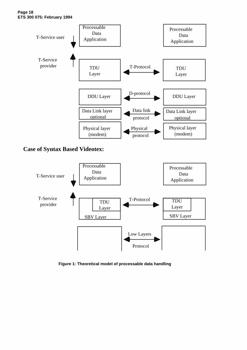
In order to allow for the transfer of files in already existing Videotex systems, as well as allowing moreadvanced facilities for future systems, the transfer is described as consisting of two layers.
Processable data, including telesoftware files, data for printing, file parameters and control data related tothe downloading procedure are transmitted by means of Telesoftware Data Units (TDUs). These TDUsare exchanged between co-operating entities according to the T-protocol. This protocol, as well as thespecific rules for telesoftware and printer device applications, are specified in Clause 6 of this ETS.
In the case of Syntax Based Videotex (SBV), the DDU protocol is not used.
Handling of these DDUs is described in Clause 8.
In addition Dialogue Data Units (DDUs) are used for adaptation to the different Videotex systems. Optional8-bit transparency capabilities and optional error detection and recovery facilities are provided.
Page 18ETS 300 075: February 1994
Processable Data
Application
Processable Data
Application
TDU Layer
TDU Layer
T-Service user
T-Service provider T-Protocol
DDU Layer DDU Layer
Data Link layer Data Link layer
Physical layer (modem)
optional optional
Physical layer (modem)
Data link
protocol
Physical
protocol
D-protocol
Processable Data
Application
Processable Data
Application
TDU Layer
TDU Layer
T-Service user
T-Service provider
T-Protocol
SBV Layer SBV Layer
Low Layers
Protocol
Case of Syntax Based Videotex:
Figure 1: Theoretical model of processable data handling
Page 19ETS 300 075: February 1994
4.1 Service definition
4.1.1 Scope and field of application
This subclause defines, in an abstract way the externally visible service provided by the TDU layer (T-service) in terms of:
a) the primitive actions and events of the service;
b) the parameter data associated with each primitive action and event;
c) the relationship between, and the valid sequence of these actions and events.
This subclause also describes the processable data applications which make use of the above-mentionedservice.
4.1.2 Model of the T-service
4.1.2.1 Services references
This ETS is based on the concepts which were developed in CCITT and ISO for the description of the OSIReference model (CCITT Recommendation X.200 [5]).
The conventions used to describe this service are based on CCITT Recommendation X.210 [6].
4.1.2.2 Services definitions
4.1.2.2.1 General terms
This ETS makes use of the following terms as defined in CCITT Recommendation X.210 [6]:
a) service user;b) service provider;c) primitive;d) request;e) indication;f) response;g) confirmation;h) confirmed, non-confirmed, provider initiated service.
4.1.2.2.2 Regimes
Three regimes are defined: the Association regime, the Access regime and the Transfer regime. In thebasic kernel only the Association and the Transfer regimes may be established.
These regimes are defined in subclause 4.1.2.3.
In the following, the functions of the regimes and their relationship with each other are specified.
An Association regime determines a period during which two applications remain associated.
An Access regime is used to allow functions to be negotiated and it determines a period during whichthese functions are available. The Access regime is never established in "basic kernel".
A Transfer regime determines a period during which a mass transfer is performed.
The mass transfer phase is related to the data transfer itself and takes place during a Transfer regime.
An Access regime is established within an Association regime, provided no other Access regime isalready established. A Transfer regime is established within an Access regime (symmetrical service) orwithin an Association regime (basic kernel), provided no other Transfer regime is already established.

Page 20ETS 300 075: February 1994
Figures 2 and 3 show examples of establishing regimes in the basic kernel and in the symmetricalservice.
Mass transfer ********** ** *** *************phases----------------------------------------- ------------------------------------------------------------------------------------------Regimes:Transfer ----------- --- ------ ------------------Association ------------------------------------------------------------------------------------------
Figure 2: Example of regimes establishment in the basic kernel
Mass transfer ********* ** *** **************phases---------------------------------------- ------------------------------------------------------------------------------------------Regimes :TransferAccess
------------ --- ------ ------------------------------------ -----------------------------------------------------
Association ------------------------------------------------------------------------------------------
Figure 3: Examples of regimes establishment in the symmetrical service
4.1.2.2.3 Roles
At a given time each entity is assigned a unique role. Within a given regime, a role determines the set ofservices for which the entity may be initiator or acceptor.
The following roles are defined:
– the Master is the entity which controls the dialogue;
– the Slave is the entity which performs the operations requested by the Master;
– the Sender is the entity which sends the data during a mass transfer;
– the Receiver is the entity which receives the data during a mass transfer.
During a whole Transfer regime a given entity keeps the same Sender or Receiver role.
After having established an Association regime the Master role is assigned to the initiating entity of theassociation establishment service, the Slave role is assigned to the accepting entity of the associationestablishment service.
At the Access regime establishment (in symmetrical service) the Master and Slave roles may be modifiedand will then remain unchanged during the whole Access regime. After the end of the Access regime theMaster role is assigned to the initiating entity of the Access regime release service, the Slave role isassigned to the accepting entity of the Access regime release service.
At the Transfer regime establishment the Sender and Receiver roles are assigned according to the masstransfer direction. The mass transfer direction is determined by the service which has been used toestablish the Transfer regime. At the end of the Transfer regime, each entity takes its own Master or Slaverole which was assigned before the Transfer regime establishment.
In the service class "basic kernel", the mass transfer is always performed in the same direction, thereforethe Sender role is always assigned to the Master, the Receiver role is always assigned to the Slave.
4.1.2.2.4 Local concepts
– The Server is the system which contains a database (which stores and retrieves informationwithout processing it). In the basic kernel the Server may be called the Host .
– The Executor is the system which processes the downloaded files.

Page 21ETS 300 075: February 1994
A given system may contain both a Server application and an Executor application. The Server andExecutor concepts are local concepts and are not related to file transmission, however this may impactimplementation subsets definition.
In the service class "basic kernel", during a whole association, the Server shall play the Master andSender roles, while the other entity is the Executor and shall play the Slave and Receiver roles.
4.1.2.3 Service elements
4.1.2.3.1 General organisation
Table 1 gives the list of the service elements:
Table 1: List of the service primitives
Service initiated by Function S B T-ASSOCIATE OC both Association establishment M M T-RELEASE C both(1) Association release M M T-U-ABORT NC both(2) Association user abort M M T-P-ABORT P both Association provider abort M - T-ACCESS C Master Access regime establishment M - T-END-ACCESS C both End of Access regime M - T-DIRECTORY C Master File Directory request O - T-LOAD C Master Init. Slave to Master mass transfer O - T-SAVE C Master Init. Master to Slave mass transfer O - T-RENAME C Master Rename file O - T-DELETE C Master Delete file O - T-TYPED-DATA NC both Typed data transfer O - T-WRITE OC Sender Data transfer M M T-WRITE-END C Sender End of data transfer M M T-U-EXCEPT NC both(3) User exception report M M T-P-EXCEPT P both Provider exception report M -
Key:
C : Confirmed serviceOC : Optionally confirmed serviceNC : Non confirmed serviceP : Provider initiated serviceB : Basic kernelS : Symmetrical serviceO : OptionalM : Mandatory(1) : May only be sent by the Master in the basic kernel(2) : May only be sent by the Slave in the basic kernel(3) : May only be sent by the Receiver in the basic kernel- : Irrelevant
Figure 4 gives the relationship between services and regimes, indicating which services are used toestablish and terminate a regime and which services are available in a given regime. The definition of theregimes is given in the following subclauses.

Page 22ETS 300 075: February 1994
Basic Kernel
ASSOCIATION REGIME
TRANSFER REGIME
MASS TRANSFER PHASE (Master to Slave)
T-WRITET-U-EXCEPTION-REPORT
T-WRITE T-WRITE-END T-U-EXCEPTION-REPORT
T-RELEASE T-U-ABORT
T-ASSOCIATE T-P-ABORT
Symmetrical service
ASSOCIATION REGIME
ACCESS REGIME
TRANSFER REGIME
MASS TRANSFER PHASE (Master to Slave or Slave to Master)
T-WRITE T-U-EXCEPTION-REPORT
T-DIRECTORY T- WRITE-END T-LOAD T-U-EXC-REPORT T-SAVE T-P-EXC-REPORT T-WRITE
T-RENAME T-DELETE T-TYPED-DATA
T-ACCESS T-END-ACCESS
T-ASSOCIATE T-RELEASET-U-ABORTT-P-ABORT
NOTE: T-U-ABORT and T-P-ABORT may be used at any time in every regime, they terminateall the currently established regimes.
Figure 4: Regimes
4.1.2.3.2 Association regime
The Association regime is established by using the association establishment service. It may beterminated by using the association release service or the association abort services.
In the idle state the Master may invoke the association abort or release services, the Access (symmetricalservice) or Transfer (basic kernel) regime establishment services.
In the idle state the Slave may invoke the association abort or release services.
4.1.2.3.3 Access regime
The Access regime is established (in symmetrical service) by using the Access regime establishmentservice. It may be terminated by using the end of Access regime service or the association abort service(in this latter case the association is also terminated).

Page 23ETS 300 075: February 1994
When the Access regime is established, the Master and the Slave may invoke the end of Access regimeservice, the association abort service or the exception report services. The Master may invoke the datatransfer, load, save, rename, delete, file directory services, the Master and the Slave may also invoke thetyped data transfer service provided that the use of those services had been negotiated during the Accessregime establishment.
4.1.2.3.4 Transfer regime
The Transfer regime is used to transmit a large amount of information (e.g. files) from the Sender to theReceiver. The mass transfer phase, which consists of performing the data transfer and end of datatransfer services, shall take place during the transfer regime.
In the symmetrical service class, a Transfer regime may be established within the Access regime by usingthe load, save or file directory services. When the Access regime is established, the Transfer regime mayalso be established implicitly by the Master by starting the mass transfer phase. When a Transfer regimeconsists only in a mass transfer phase (i.e. it is directly established by issuing a data transfer serviceprimitive) the transfer is called Basic Transfer Mode. In the symmetrical service class, the use of the BasicTransfer Mode is negotiated at the Access regime establishment and is exclusive of the use of filedirectory, load or save services.
In the basic kernel, a Transfer regime is reduced to the mass transfer phase (Basic Transfer Mode).Therefore the Transfer regime is established when the Association regime is established by starting themass transfer phase.
A Transfer regime may be terminated by using the end of data transfer service, the exception reportservice or the association abort services.
During the Transfer regime, the Sender may invoke the data transfer service, the end of data transferservice, the exception report services or the association abort services. The Receiver may invoke theexception report services and the association abort services. In the symmetrical service only the Receivermay invoke the user exception report service.
4.1.2.3.5 Restrictions on the use of services
Subclauses 4.1.2.3.2, 4.1.2.3.3 and 4.1.2.3.4 specify which services may be used in each regime.
Moreover, between sending a confirmed service request and receiving the corresponding confirmation (atthe service initiator side) or between receiving a confirmed service indication and sending thecorresponding response (at the service acceptor side), no other service shall be initiated except theexception report, or association abort services. This restriction is not applicable to the data transferservices when the window size is greater than 1 and in the conditions described in subclause 4.1.2.4.3.
4.1.2.4 Concepts related to mass transfer
In order to facilitate the transfer of a large amount of information various mechanisms are provided.
The main notion is the recovery point. The recovery points are located at the beginning of the masstransfer phase and at each confirmed data transfer primitive.
In the symmetrical service, the size of transfer units (conveyed within a data transfer primitive) isnegotiated during the Access regime establishment.
4.1.2.4.1 Recovery during a mass transfer
Several facilities are provided to recover during a mass transfer phase:
– the Receiver may request to restart the transmission at the beginning of the mass transfer phase.This facility is always available in the basic kernel and it is negotiated during the Access regimeestablishment in the symmetrical service;
– during the mass transfer, the transmission may be resumed from the last confirmed data transferprimitive, this may be done by sending a negative response to a data transfer primitive. The
Page 24ETS 300 075: February 1994
transmission is resumed from the data which immediately followed the last data for which a positiveconfirmation had been received by the Sender or, if not, at the beginning of the transfer.
4.1.2.4.2 Recovery outside a mass transfer
The recovery outside a mass transfer phase is carried out when the mass transfer phase has beeninterrupted. This recovery may take place during the same association or during another association thanthe original transfer. This mechanism is only available in the symmetrical service when using Load orSave services and if it is negotiated during the Access regime establishment.
When the recovery outside a mass transfer has been negotiated, the Sender shall associate a recoverypoint number to each transfer unit and each data transfer primitive shall be confirmed.
NOTE 1: The service does not ensure that the information for which the transmission isresumed are consistent with the previously transmitted information. It is up to theservice user to provide means for a correct recovery (e.g. storage of the interruptedtransfer context, file version number ...).
The recovery request is performed by indicating a recovery point number in a parameter of the T-SAVErequest or T-LOAD request primitives. The transmission is resumed starting with the data whichimmediately followed the indicated recovery point in the original transfer. The indicated recovery pointcorresponds to the last data transfer primitive for which a positive confirmation had been received or sent.
NOTE 2: After a transfer interruption, it may happen that the recovery point number, from theSender point of view, will be lower than the recovery point number from the Receiverpoint of view. It is up to the Receiver to verify that no data duplication occurs in case ofrecovery.
4.1.2.4.3 Anticipation window
The anticipation mechanism gives the ability to send several data transfer primitives with explicitconfirmation requested, without waiting for having received the confirmation of the previous ones. The aimof the window mechanism is to improve the transmission efficiency by avoiding idle periods due to thewaiting of confirmations.
The anticipation window is the number of recovery points (i.e. the number of data transfer primitives withexplicit confirmation requested) which the Sender may send without having received any confirmation.When there is no anticipation the window size is equal to 1.
When the anticipation window size is greater than 1, the Sender shall associate a recovery point numberto each transfer unit and each data transfer primitive shall be confirmed.
In the basic kernel the window size is always equal to 1.
In symmetrical service, the window size is negotiated during the Access regime establishment. Each entityindicates the window size it may accept when the entity plays the role of Receiver. However, the Sendermay use, for sending, a window of a lower value than the value indicated by the Receiver (i.e. the Senderis not bound to fill in the sending window). The Receiver shall confirm the recovery points "as soon aspossible" and should not wait until the window maximum value is reached to confirm them (this value maynever be reached if the Sender uses a lower window size for sending).
When the value of the maximum window size is reached the Sender is no longer permitted to send datauntil it receives an explicit confirmation to a previous recovery point. The recovery points are set byincrementing the recovery point number by one for each new recovery point and they are explicitlyconfirmed (one by one) in the increasing order of their reception.
4.1.3 Association regime control
If the association establishment service requires confirmation, the Association regime is established assoon as the acceptor has sent a T-ASSOCIATE Response (positive) and, at the initiator's end, a T-ASSOCIATE Confirmation (positive) has been received.

Page 25ETS 300 075: February 1994
If the association establishment does not require confirmation, the Association regime is established assoon as the initiator has sent a T-ASSOCIATE Request and, at the acceptor's end, a T-ASSOCIATEIndication has been received.
The Association regime is terminated upon transmission of T-RELEASE Response or T-U-ABORTRequest and upon reception of T-RELEASE Confirmation, T-U-ABORT Indication or T-P-ABORTIndication.
4.1.3.1 Association establishment
4.1.3.1.1 Function
T-ASSOCIATE is used by a service user to associate with a specified processable data application(identified by the "application name" parameter).
The T-ASSOCIATE Request primitive is used to establish an Association regime, this primitive shall notbe used when the association is being established or is already established.
In the basic kernel, a T-ASSOCIATE request may only be initiated by the host.
T-ASSOCIATE is an optionally confirmed service, the parameter "explicit confirmation" indicates whetheror not an explicit confirmation is requested.
4.1.3.1.2 Parameters
The different primitives and parameters required by the association establishment service are describedas below.
Parameter T-ASSOCIATERequest
T-ASSOCIATEIndication
T-ASSOCIATEResponse
T-ASSOCIATEConfirmation
S
Service class Mandatory Mandatory(=) Mandatory Mandatory(=)Called address Optional Optional(=) Optional Optional(=) SCalling address Optional Optional(=) SAppl. name Mandatory Mandatory(=)Explicit conf. Mandatory Mandatory(=)Timeouts Optional Optional(=) Optional Optional(=)Request ident. Optional Optional(=) SIdentification Optional Optional(=) Optional Optional(=) SUser data Optional Optional(=) Optional Optional(=)Result Mandatory Mandatory
(=): the value of the parameter is identical to the value of the corresponding parameter in thepreceding request or response primitive.
S: symmetrical service only.
4.1.3.1.2.1 Service class
This parameter is used to indicate the service class in use. It may take the following values:
a) "basic kernel";b) "symmetrical service".
In the Request/Indication it indicates the service class(es) proposed.
In the Response/Confirmation it announces the service class selected if the association is accepted.
Page 26ETS 300 075: February 1994
4.1.3.1.2.2 Called address
This parameter indicates the address of the entity which has sent a response or a confirmation. Thisaddress may differ from the parameter provided in the request or the indication (this can be the case afterrerouting).
This parameter shall not be used if the service class parameter indicates only the value "basic kernel".
4.1.3.1.2.3 Calling address
This parameter provides the address of the entity which originated the association.
This parameter shall not be used if the service class parameter indicates only the value "basic kernel".
4.1.3.1.2.4 Application name
The parameter "application name" announces the use of a specified processable data application. Thisparameter is a variable length string.
The following standardised names are defined:
!A: Any application (including telesoftware and printer);!T: Telesoftware;!P: Printer device.
Names starting with ! are reserved for standardised applications.
4.1.3.1.2.5 Explicit confirmation
This parameter is used in the basic kernel to indicate whether or not explicit confirmation is requested.
If the service class parameter indicates "Symmetrical Service", this parameter shall be set to indicate thatconfirmation is requested.
4.1.3.1.2.6 Timeouts
In the basic kernel, this parameter indicates the master's maximum response time and contains themaximum value of the delay between a response primitive issued by the slave and the next indicationprimitive. This delay is controlled by the service provider. Absence of this parameter means that this delayshall not be controlled by the service provider.
In the symmetrical service, this parameter specifies the maximum response time required to answer arequest. Each entity is responsible for defining their own response time. This response time is controlledby the service provider at the other end.
Absence of this parameter means in both cases, that the response time shall not be checked by theservice provider.
4.1.3.1.2.7 Request identification
This parameter enables the initiator to require identification in the Response/Confirmation. It may take thetwo following values:
a) identification required;b) identification not required.
This parameter shall not be used if the service class parameter indicates only the value "basic kernel".
4.1.3.1.2.8 Identification
This parameter is a variable length string, of no more than 254 bytes. It provides identification data on theuser of this service.

Page 27ETS 300 075: February 1994
This parameter shall not be used if the service class parameter indicates only the value "basic kernel".
4.1.3.1.2.9 User data
This parameter is used to convey string type information of no more than 254 bytes.
In the basic kernel this parameter shall not be used in the T-ASSOCIATE response and T-ASSOCIATEconfirmation.
4.1.3.1.2.10 Result
This parameter indicates whether the association is accepted or rejected.
If the selected service class is the symmetrical service, possible values of this parameter are the following:
a) association request accepted;
b) association request rejected. Reason not specified;
c) reject from the service provider, reason:
- called address incorrect;- calling address incorrect;- service class refused.
d) reject from the service user, reason:
- called address incorrect;- calling address incorrect;- service class refused;- application's name unknown;- wrong identification;- erroneous user data;- other reason.
If the selected service class is the basic kernel, the value of this parameter can be either:
1) association request accepted;
2) association request rejected.
4.1.3.1.3 Association establishment operation
In the case when an explicit confirmation is requested by the parameter "explicit confirmation", thecorresponding response primitive shall be sent by the receiver before any other protocol exchange.
T-ASSOCIATE request | |----------------> | | T-ASSOCIATE indication
| | ---------------->| || | T-ASSOCIATE response
T-ASSOCIATE confirmation | | <----------------<---------------- | |
If explicit confirmation is not requested and if the application specified in a T-ASSOCIATE is not availableat the acceptor's side or in the case of any user error, then the acceptor shall use the T-U-ABORT service.

Page 28ETS 300 075: February 1994
4.1.3.2 Association release
4.1.3.2.1 Function
An Association regime may be terminated by the exchange of T-RELEASE primitives. This service maybe used only once the Association regime is established and provided no other regime is established.
The T-RELEASE service is thus used to request the orderly termination of the processable dataapplication.
If the selected service class is the basic kernel only the Master may issue a T-RELEASE request.
4.1.3.2.2 Parameters
The different primitives and parameters required by the association release service are described below.
Parameter T-RELEASERequest
T-RELEASEIndication
T-RELEASEResponse
T-RELEASEConfirmation
User data Optional Optional(=) Optional Optional(=) Result Mandatory Mandatory(=): the value of the parameter is identical to the value of the corresponding parameter in thepreceding request or response primitive.
4.1.3.2.2.1 User data
This parameter is used to convey string type information of no more than 254 bytes.
In the basic kernel, this parameter shall not be used in the T-RELEASE response and T-RELEASEconfirmation.
4.1.3.2.2.2 Result
This parameter always indicates that the T-Release service has been accepted.
4.1.3.2.3 Association release operation
T-RELEASE request | |----------------> | | T-RELEASE indication
| | ---------------->| || | T-RELEASE response
T-RELEASE confirmation | | <----------------<---------------- | |
4.1.3.3 Association abort
4.1.3.3.1 Function
This service is performed by the primitives T-U-ABORT Request when it is user initiated, by T-P-ABORTwhen it is provider initiated.
In the basic kernel a T-U-ABORT request may only be initiated by the slave. T-P-ABORT is not used inthe basic kernel.
A T-U-ABORT request may be sent by the user of the T-Service at any time after reception of aT-ASSOCIATE Indication or after transmission of a T-ASSOCIATE Request. The provider of theT-Service may issue a T-P-ABORT Indication at any time after reception of a T-ASSOCIATE Request orafter transmission of T-ASSOCIATE Indication.
It is recommended to avoid the use of the T-U-ABORT service to reject a T-ASSOCIATE for which explicitconfirmation was requested.

Page 29ETS 300 075: February 1994
These primitives terminate the association regime abnormally. Data may be lost.
4.1.3.3.2 Parameters
The different primitives and parameters required by the abort service are described below.
Parameter T-U-ABORTrequest
T-U-ABORTindication
Reason Mandatory
Reason (user):
reason not specified;incorrect identification;incorrect role/function;other reason.
If the service class is the basic kernel this parameter is always equal to "reason not specified".
Parameter T-P-ABORTindication
Reason Mandatory
Reason (provider):
reason not specified;repeated negative acknowledgements/repeated errors;delay expired;unknown message;protocol conflict;lower layer error;syntax error/parameter's absence;other reason.
4.1.3.3.3 Association abort operation
T-U-ABORT request | |----------------> | | T-U-ABORT indication
| | ---------------->
T-P-ABORT indication | |<---------------- | | T-P-ABORT indication
| | ---------------->
4.1.4 Access regime control
The Access regime is established upon transmission of the primitive T-ACCESS Response (positive) onthe acceptor's side and upon reception of the primitive T-ACCESS Confirmation (positive) on the initiator'sside.
The Access regime is terminated upon transmission of the primitive T-END-ACCESS Response or T-U-ABORT Request (on the acceptor's side) and upon reception of the primitive T-END-ACCESSConfirmation, T-U-ABORT Indication or T-P-ABORT Indication (on the initiator's side).
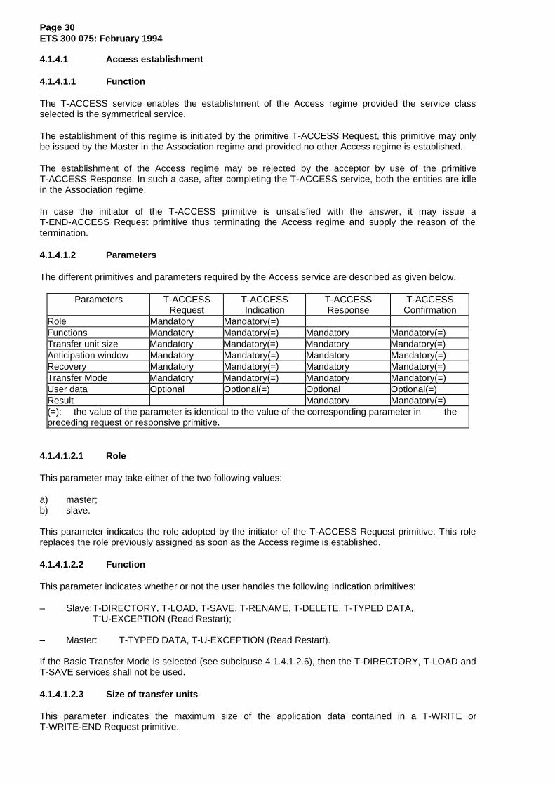
Page 30ETS 300 075: February 1994
4.1.4.1 Access establishment
4.1.4.1.1 Function
The T-ACCESS service enables the establishment of the Access regime provided the service classselected is the symmetrical service.
The establishment of this regime is initiated by the primitive T-ACCESS Request, this primitive may onlybe issued by the Master in the Association regime and provided no other Access regime is established.
The establishment of the Access regime may be rejected by the acceptor by use of the primitiveT-ACCESS Response. In such a case, after completing the T-ACCESS service, both the entities are idlein the Association regime.
In case the initiator of the T-ACCESS primitive is unsatisfied with the answer, it may issue aT-END-ACCESS Request primitive thus terminating the Access regime and supply the reason of thetermination.
4.1.4.1.2 Parameters
The different primitives and parameters required by the Access service are described as given below.
Parameters T-ACCESSRequest
T-ACCESSIndication
T-ACCESSResponse
T-ACCESSConfirmation
Role Mandatory Mandatory(=)Functions Mandatory Mandatory(=) Mandatory Mandatory(=)Transfer unit size Mandatory Mandatory(=) Mandatory Mandatory(=)Anticipation window Mandatory Mandatory(=) Mandatory Mandatory(=)Recovery Mandatory Mandatory(=) Mandatory Mandatory(=)Transfer Mode Mandatory Mandatory(=) Mandatory Mandatory(=)User data Optional Optional(=) Optional Optional(=)Result Mandatory Mandatory(=)(=): the value of the parameter is identical to the value of the corresponding parameter in thepreceding request or responsive primitive.
4.1.4.1.2.1 Role
This parameter may take either of the two following values:
a) master;b) slave.
This parameter indicates the role adopted by the initiator of the T-ACCESS Request primitive. This rolereplaces the role previously assigned as soon as the Access regime is established.
4.1.4.1.2.2 Function
This parameter indicates whether or not the user handles the following Indication primitives:
– Slave:T-DIRECTORY, T-LOAD, T-SAVE, T-RENAME, T-DELETE, T-TYPED DATA, T-U-EXCEPTION (Read Restart);
– Master: T-TYPED DATA, T-U-EXCEPTION (Read Restart).
If the Basic Transfer Mode is selected (see subclause 4.1.4.1.2.6), then the T-DIRECTORY, T-LOAD andT-SAVE services shall not be used.
4.1.4.1.2.3 Size of transfer units
This parameter indicates the maximum size of the application data contained in a T-WRITE orT-WRITE-END Request primitive.
Page 31ETS 300 075: February 1994
The following values are permitted:
512, 1 024, 2 048, 4 096, 8 192,16 384, 32 768, 65 528 bytes
In the basic kernel this parameter shall not be used and the value is 1 024 bytes.
4.1.4.1.2.4 Anticipation window
This parameter indicates the maximum number of consecutive T-WRITE or T-WRITE-END (confirmationrequired) primitives the user is allowed to receive before issuing an answer.
It may take a value ranging from 1 to 8.
This parameter shall not be used in the basic kernel, the value is 1.
4.1.4.1.2.5 Recovery
This parameter indicates whether or not the slave is able to handle the recovery mechanism upontransmission and reception of files.
4.1.4.1.2.6 Transfer mode
This parameter may take one of the two following values:
a) Basic Transfer Mode supported (Slave) or Basic Transfer Mode required (Master);
b) Basic Transfer Mode not supported (Slave) or Basic Transfer Mode not required (Master).
If the Master indicates that it requires the use of the Basic Transfer Mode and the Slave indicates that itsupports this mode, then the Basic Transfer Mode is selected. This means that only this mode may beused to transfer files and that the Load, Save or Directory functions shall not be used during the Accessregime whatever the Slave indicated in the Function parameter. Otherwise the Basic Transfer Mode shallnot be used (only the other functions indicated in the Function parameter may be used).
4.1.4.1.2.7 User data
This parameter is used to convey string type information of no more than 254 bytes.
4.1.4.1.2.8 Result
This parameter indicates whether or not the service has been accepted or rejected.
This parameter may take one of the following values:
a) access request accepted;
b) access request rejected. Reason not specified;
c) refusal from the service provider, reason:
- role refused;
d) refusal from the service user, reason:
- role refused;- insufficient primitives handled;- erroneous user data;- other reason.

Page 32ETS 300 075: February 1994
4.1.4.2 End of Access service
4.1.4.2.1 Function
The Access regime may be terminated using a T-END-ACCESS primitive. The T-END-ACCESS Requestprimitive shall only be issued within the idle state of the Access regime.
It may be initiated by both the Master and the Slave.
4.1.4.2.2 Parameters
The different primitives and parameters required by the End Access service are described as follows.
Parameters T-END-ACCESSRequest
T-END-ACCESSIndication
T-END-ACCESSResponse
T-END-ACCESSConfirmation
User dataResult
Optional Mandatory
Optional(=)Mandatory(=)
Optional Optional(=)
(=): the value of the parameter is identical to the value of the corresponding parameter in the preceding request or response primitive.
4.1.4.2.2.1 User data
This parameter is used to convey string type information of no more than 254 bytes.
4.1.4.2.2.2 Result
This parameter indicates the reason of the Access regime termination:
- reason not specified;- insufficient primitives handled;- other reason.
4.1.4.3 File directory service
4.1.4.3.1 Function
The File directory service enables the Master to request the transfer of one file directory from the Slave tothe Master and the establishment of the Transfer regime. This service is not available in the basic kernel.
Only the Master may issue a T-DIRECTORY Request, provided the Access regime is established and theuse of T-DIRECTORY has been accepted by the Slave at the time the Access regime was established.
The information is transferred from the Slave to the Master after the Slave has answered byT-DIRECTORY Response (accept). A positive response establishes the Transfer regime.
In the Transfer regime the Slave becomes Sender and the Master becomes Receiver.
4.1.4.3.2 Parameters
The different primitives and parameters required by the file directory service are described below.
Parameters T-DIRECTORYRequest
T-DIRECTORYIndication
T-DIRECTORYResponse
T-DIRECTORYConfirmation
DesignationUser dataResult
MandatoryOptional
Mandatory(=)Optional(=)
Mandatory Mandatory(=)(=): the value of the parameter is identical to the value of the corresponding parameter in the
preceding request or response primitive.

Page 33ETS 300 075: February 1994
4.1.4.3.2.1 Designation
This parameter enables the Master to designate the directory it requires. It is a byte sequence of no morethan 254 bytes.
4.1.4.3.2.2 User data
This parameter is used to convey string type information of no more than 254 bytes.
4.1.4.3.2.3 Result
This parameter enables the Slave to indicate acceptance or refusal of the directory request.
This parameter may take one of the following values:
a) acceptance;
b) user refusal, reason:
- reason not specified;- erroneous designation;- no answer to the request;- erroneous user data;- other reason.
4.1.4.4 Load service
4.1.4.4.1 Function
The Load service enables the Master to request the transfer of one file from the Slave to the Master andestablishes the Transfer regime.
The Load service shall not be used if the Basic Transfer Mode is used (the Basic Transfer Mode is used inthe basic kernel or as an option of the Symmetrical Service).
Only the Master may issue a T-LOAD Request, provided the Access regime is established and the use ofT-LOAD has been accepted by the Slave at the time the Access regime was established.
The information is transferred from the Slave to the Master after the Slave has answered by T-LOADResponse (accept). A positive response establishes the Transfer regime.
In the Transfer regime the Slave becomes Sender and the Master Receiver.
4.1.4.4.2 Parameters
The different primitives and parameters required by the Load service are described as given below.
Parameters T-LOAD Request T-LOAD Indication T-LOAD Response T-LOADConfirmation
Recovery point Optional Optional(=)Designation Mandatory Mandatory(=)User data Optional Optional(=)Result Mandatory Mandatory(=)(=): the value of the parameter is identical to the value of the corresponding parameter in thepreceding request or response primitive.
4.1.4.4.2.1 Recovery point
This parameter is used to enable the Master to indicate the recovery point which corresponds to the lastdata transfer primitive for which a positive confirmation had been sent. The Transfer will be resumed from

Page 34ETS 300 075: February 1994
the data transfer service immediately following the indicated recovery point. The value of the recoverypoint is in the range 0 to 65 535.
This parameter shall not be used if the recovery function has not been accepted at the time the Accessregime was established.
4.1.4.4.2.2 Designation
This parameter enables the Master to designate the information it requires. It is a byte sequence of nomore than 254 bytes.
4.1.4.4.2.3 User data
This parameter is used to convey string type information of no more than 254 bytes.
4.1.4.4.2.4 Result
This parameter enables the Slave to indicate acceptance or refusal of the load request.
This parameter may take one of the following values:
a) acceptance;
b) user refusal, reason:
- reason not specified;- erroneous designation;- unknown file;- erroneous recovery point;- erroneous user data;- other reason.
4.1.4.5 Save service
4.1.4.5.1 Function
The Save service enables the Master to request the transfer of one file from the Master to the Slave andestablishes the Transfer regime. This service is not available in the basic kernel.
Only the Master may issue a T-SAVE Request, provided the Access regime is established and the use ofT-SAVE has been accepted by the Slave at the time the Access regime was established.
The information is transferred from the Master to the Slave after the Slave has answered by T-SAVEResponse (accept). A positive response establishes the Transfer regime.
In the Transfer regime the Slave becomes Receiver and the Master Sender.
4.1.4.5.2 Parameters
The different primitives and parameters required by the Save service are described below.
Parameters T-SAVE Request T-SAVE Indication T-SAVE Response T-SAVEConfirmation
Recovery point Optional Optional(=)Designation Mandatory Mandatory(=)User data Optional Optional(=)Result Mandatory Mandatory(=)(=): the value of the parameter is identical to the value of the corresponding parameter in thepreceding request or response primitive.

Page 35ETS 300 075: February 1994
4.1.4.5.2.1 Recovery point
This parameter is used to enable the Master to indicate the recovery point which corresponds to the lastdata transfer primitive for which a positive confirmation had been received. The Transfer shall be resumedfrom the data transfer service immediately following the indicated recovery point. The value of therecovery point is in the range 0 to 65 535.
This parameter shall not be used if the recovery function has not been accepted at the time the Accessregime was established.
4.1.4.5.2.2 Designation
This parameter enables the Master to designate the information it wants to save. It is a byte sequence ofno more than 254 bytes.
4.1.4.5.2.3 User data
This parameter is used to convey string type information of no more than 254 bytes.
4.1.4.5.2.4 Result
This parameter enables the Slave to indicate acceptance or refusal of the save request.
This parameter may take one of the following values:
a) acceptance;
b) user refusal, reason:
- reason not specified;- erroneous designation;- file already exist;- erroneous recovery point;- erroneous user data;- other reason.
4.1.4.6 Rename service
4.1.4.6.1 Function
The Rename service enables the Master to rename the designation of a file within the Slave. This serviceis not available in the basic kernel.
Only the Master may issue a T-RENAME Request, provided the Access regime is established and the useof T-RENAME has been accepted by the Slave at the time the Access regime was established.
4.1.4.6.2 Parameters
The different primitives and parameters required by the Rename service are described below.
Parameters T-RENAMERequest
T-RENAMEIndication
T-RENAMEResponse
T-RENAMEConfirmation
New name Mandatory Mandatory(=)Designation Mandatory Mandatory(=)User data Optional Optional(=)Result Mandatory Mandatory(=)(=): the value of the parameter is identical to the value of the corresponding parameter in thepreceding request or response primitive.

Page 36ETS 300 075: February 1994
4.1.4.6.2.1 New name
This parameter provides the new designation for the required information. It is a byte sequence of nomore than 254 bytes.
4.1.4.6.2.2 Designation
This parameter enables the Master to designate the information it requires to be renamed. It is a bytesequence of no more than 254 bytes.
4.1.4.6.2.3 User data
This parameter is used to convey string type information of no more than 254 bytes.
4.1.4.6.2.4 Result
This parameter enables the Slave to indicate acceptance or refusal of the rename request.
This parameter may take one of the following values:
a) acceptance;
b) user refusal, reason:
- reason not specified;- erroneous designation;- erroneous new name;- unknown file;- new name already in use;- erroneous user data;- other reason.
4.1.4.7 Delete service
4.1.4.7.1 Function
The Delete service enables the Master to delete a file within the Slave. This service is not available in thebasic kernel.
Only the Master may issue a T-DELETE Request, provided the Access regime is established and the useof T-DELETE has been accepted by the Slave at the time the Access regime was established.
4.1.4.7.2 Parameters
The different primitives and parameters required by the Delete service are described below.
Parameters T-DELETERequest
T-DELETEIndication
T-DELETEResponse
T-DELETEConfirmation
Designation Mandatory Mandatory(=)User data Optional Optional(=)Result Mandatory Mandatory(=)(=): the value of the parameter is identical to the value of the corresponding parameter in thepreceding request or response primitive.
4.1.4.7.2.1 Designation
This parameter enables the Master to designate the information it requires to be deleted. It is a bytesequence of no more than 254 bytes.
4.1.4.7.2.2 User data
This parameter is used to convey string type information of no more than 254 bytes.
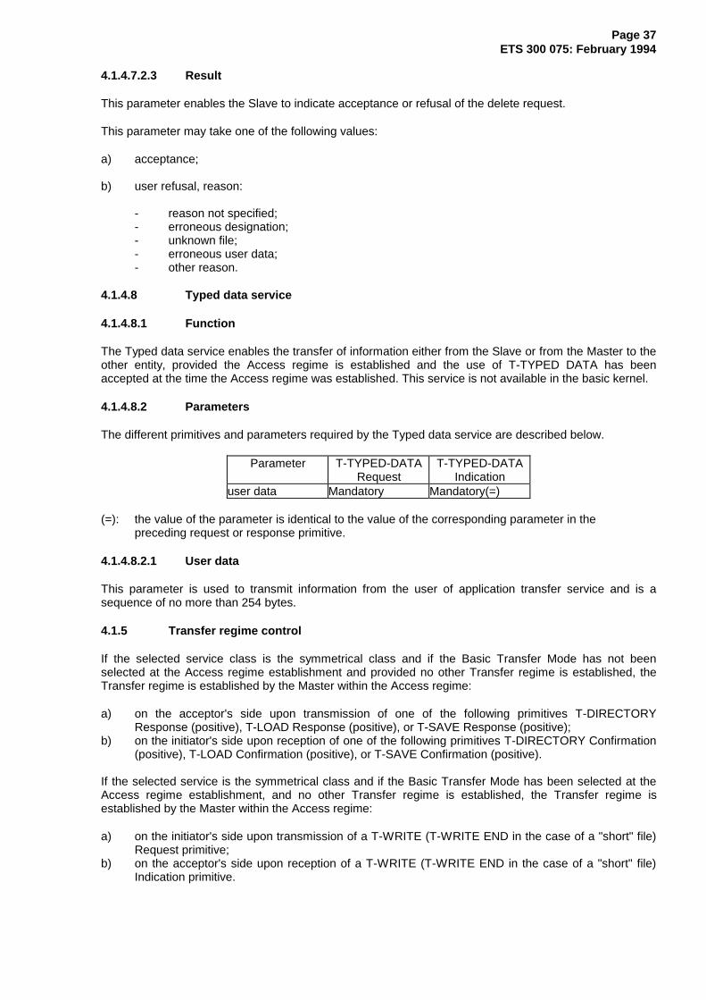
Page 37ETS 300 075: February 1994
4.1.4.7.2.3 Result
This parameter enables the Slave to indicate acceptance or refusal of the delete request.
This parameter may take one of the following values:
a) acceptance;
b) user refusal, reason:
- reason not specified;- erroneous designation;- unknown file;- erroneous user data;- other reason.
4.1.4.8 Typed data service
4.1.4.8.1 Function
The Typed data service enables the transfer of information either from the Slave or from the Master to theother entity, provided the Access regime is established and the use of T-TYPED DATA has beenaccepted at the time the Access regime was established. This service is not available in the basic kernel.
4.1.4.8.2 Parameters
The different primitives and parameters required by the Typed data service are described below.
Parameter T-TYPED-DATARequest
T-TYPED-DATAIndication
user data Mandatory Mandatory(=)
(=): the value of the parameter is identical to the value of the corresponding parameter in the preceding request or response primitive.
4.1.4.8.2.1 User data
This parameter is used to transmit information from the user of application transfer service and is asequence of no more than 254 bytes.
4.1.5 Transfer regime control
If the selected service class is the symmetrical class and if the Basic Transfer Mode has not beenselected at the Access regime establishment and provided no other Transfer regime is established, theTransfer regime is established by the Master within the Access regime:
a) on the acceptor's side upon transmission of one of the following primitives T-DIRECTORYResponse (positive), T-LOAD Response (positive), or T-SAVE Response (positive);
b) on the initiator's side upon reception of one of the following primitives T-DIRECTORY Confirmation(positive), T-LOAD Confirmation (positive), or T-SAVE Confirmation (positive).
If the selected service is the symmetrical class and if the Basic Transfer Mode has been selected at theAccess regime establishment, and no other Transfer regime is established, the Transfer regime isestablished by the Master within the Access regime:
a) on the initiator's side upon transmission of a T-WRITE (T-WRITE END in the case of a "short" file)Request primitive;
b) on the acceptor's side upon reception of a T-WRITE (T-WRITE END in the case of a "short" file)Indication primitive.
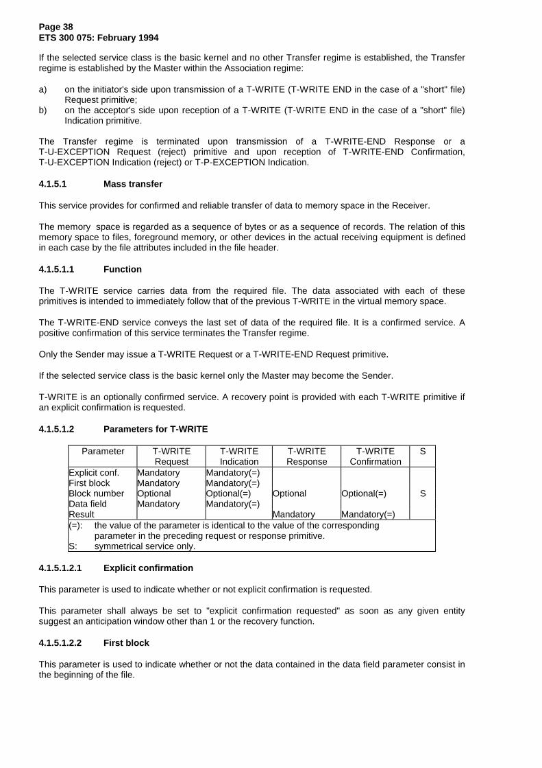
Page 38ETS 300 075: February 1994
If the selected service class is the basic kernel and no other Transfer regime is established, the Transferregime is established by the Master within the Association regime:
a) on the initiator's side upon transmission of a T-WRITE (T-WRITE END in the case of a "short" file)Request primitive;
b) on the acceptor's side upon reception of a T-WRITE (T-WRITE END in the case of a "short" file)Indication primitive.
The Transfer regime is terminated upon transmission of a T-WRITE-END Response or aT-U-EXCEPTION Request (reject) primitive and upon reception of T-WRITE-END Confirmation,T-U-EXCEPTION Indication (reject) or T-P-EXCEPTION Indication.
4.1.5.1 Mass transfer
This service provides for confirmed and reliable transfer of data to memory space in the Receiver.
The memory space is regarded as a sequence of bytes or as a sequence of records. The relation of thismemory space to files, foreground memory, or other devices in the actual receiving equipment is definedin each case by the file attributes included in the file header.
4.1.5.1.1 Function
The T-WRITE service carries data from the required file. The data associated with each of theseprimitives is intended to immediately follow that of the previous T-WRITE in the virtual memory space.
The T-WRITE-END service conveys the last set of data of the required file. It is a confirmed service. Apositive confirmation of this service terminates the Transfer regime.
Only the Sender may issue a T-WRITE Request or a T-WRITE-END Request primitive.
If the selected service class is the basic kernel only the Master may become the Sender.
T-WRITE is an optionally confirmed service. A recovery point is provided with each T-WRITE primitive ifan explicit confirmation is requested.
4.1.5.1.2 Parameters for T-WRITE
Parameter T-WRITERequest
T-WRITEIndication
T-WRITEResponse
T-WRITEConfirmation
S
Explicit conf. Mandatory Mandatory(=)First block Mandatory Mandatory(=)Block number Optional Optional(=) Optional Optional(=) SData field Mandatory Mandatory(=)Result Mandatory Mandatory(=)(=): the value of the parameter is identical to the value of the corresponding
parameter in the preceding request or response primitive.S: symmetrical service only.
4.1.5.1.2.1 Explicit confirmation
This parameter is used to indicate whether or not explicit confirmation is requested.
This parameter shall always be set to "explicit confirmation requested" as soon as any given entitysuggest an anticipation window other than 1 or the recovery function.
4.1.5.1.2.2 First block
This parameter is used to indicate whether or not the data contained in the data field parameter consist inthe beginning of the file.

Page 39ETS 300 075: February 1994
4.1.5.1.2.3 Block number
In the basic kernel this parameter is absent.
In the symmetrical service, the block number is mandatory if the recovery mechanism is selected or theanticipation window is not 1. In this case every block is numbered and the block number is increased by 1at each transmission of a new block. The block number is in the range 0 to 65 535. The first block is 0.
If a block number is present in a request, it shall be sent back in the response.
4.1.5.1.2.4 Data field
It is used to convey data from the file, it is a variable length string of no more than 1 024 bytes in the basickernel, and the maximum length is negotiated in the symmetrical service during the establishment of theAccess regime.
4.1.5.1.2.5 Result
This parameter indicates, if the explicit confirmation has been requested, that the service has beenaccepted or rejected. The result parameter set to "reject" has the effect of restarting the transmission fromthe T-WRITE following the last confirmed T-WRITE (or from the first T-WRITE of the file if no T-WRITEwas previously confirmed).
4.1.5.1.3 Parameters for T-WRITE-END
The T-WRITE-END service is a confirmed service, so the corresponding response code should be sent bythe receiver before any other protocol exchange.
Parameter T-WRITE-ENDRequest
T-WRITE-ENDIndication
T-WRITE-ENDResponse
T-WRITE-ENDConfirmation
S
First block Mandatory Mandatory(=)Block number Optional Optional(=) Optional Optional(=) SData field Optional Optional(=)Result Mandatory Mandatory(=)(=): the value of the parameter is identical to the value of the corresponding
parameter in the preceding request or response primitive.
4.1.5.1.3.1 First block
This parameter is used to indicate whether or not the data contained in the data field parameter consist inthe beginning of the file.
4.1.5.1.3.2 Block number
In the basic kernel this parameter is absent.
In the symmetrical service, the block number is mandatory if the recovery mechanism is selected or theanticipation window is not 1. The block number is in the range 0 to 65 535. The first block is 0.
If a block number is present in a request, it shall be sent back in the response.
4.1.5.1.3.3 Data field
It is used to convey data from the file, it is a variable length string of no more than 1 024 bytes in the basickernel, and the maximum length is negotiated in the symmetrical service during the establishment of theAccess regime.
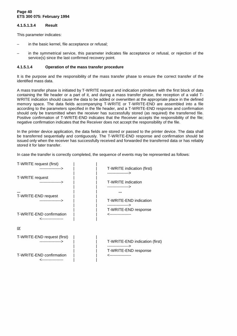
Page 40ETS 300 075: February 1994
4.1.5.1.3.4 Result
This parameter indicates:
– in the basic kernel, file acceptance or refusal;
– in the symmetrical service, this parameter indicates file acceptance or refusal, or rejection of theservice(s) since the last confirmed recovery point.
4.1.5.1.4 Operation of the mass transfer procedure
It is the purpose and the responsibility of the mass transfer phase to ensure the correct transfer of theidentified mass data.
A mass transfer phase is initiated by T-WRITE request and indication primitives with the first block of datacontaining the file header or a part of it, and during a mass transfer phase, the reception of a valid T-WRITE indication should cause the data to be added or overwritten at the appropriate place in the definedmemory space. The data fields accompanying T-WRITE or T-WRITE-END are assembled into a fileaccording to the parameters specified in the file header, and a T-WRITE-END response and confirmationshould only be transmitted when the receiver has successfully stored (as required) the transferred file.Positive confirmation of T-WRITE-END indicates that the Receiver accepts the responsibility of the file;negative confirmation indicates that the Receiver does not accept the responsibility of the file.
In the printer device application, the data fields are stored or passed to the printer device. The data shallbe transferred sequentially and contiguously. The T-WRITE-END response and confirmation should beissued only when the receiver has successfully received and forwarded the transferred data or has reliablystored it for later transfer.
In case the transfer is correctly completed, the sequence of events may be represented as follows:
T-WRITE request (first) | |----------------> | | T-WRITE indication (first)
| | ---------------->T-WRITE request | |
----------------> | | T-WRITE indication| | ---------------->
... | | ...T-WRITE-END request | |
----------------> | | T-WRITE-END indication| | ---------------->| | T-WRITE-END response
T-WRITE-END confirmation | | <----------------<---------------- | |
or
T-WRITE-END request (first) | |----------------> | | T-WRITE-END indication (first)
| | ---------------->| | T-WRITE-END response
T-WRITE-END confirmation | | <----------------<---------------- | |
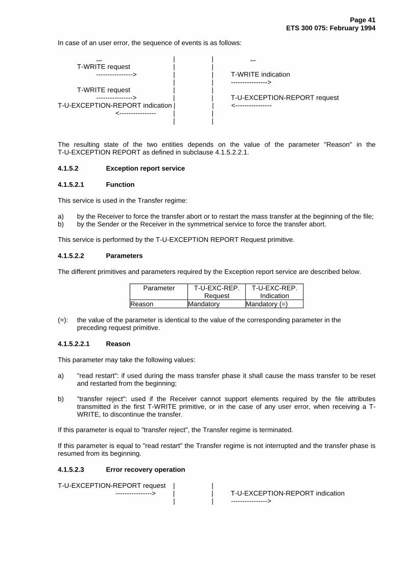
Page 41ETS 300 075: February 1994
In case of an user error, the sequence of events is as follows:
... | | ...T-WRITE request | |
----------------> | | T-WRITE indication| | ---------------->
T-WRITE request | |----------------> | | T-U-EXCEPTION-REPORT request
T-U-EXCEPTION-REPORT indication | | <----------------<---------------- | |
| |
The resulting state of the two entities depends on the value of the parameter "Reason" in theT-U-EXCEPTION REPORT as defined in subclause 4.1.5.2.2.1.
4.1.5.2 Exception report service
4.1.5.2.1 Function
This service is used in the Transfer regime:
a) by the Receiver to force the transfer abort or to restart the mass transfer at the beginning of the file;b) by the Sender or the Receiver in the symmetrical service to force the transfer abort.
This service is performed by the T-U-EXCEPTION REPORT Request primitive.
4.1.5.2.2 Parameters
The different primitives and parameters required by the Exception report service are described below.
Parameter T-U-EXC-REP.Request
T-U-EXC-REP.Indication
Reason Mandatory Mandatory (=)
(=): the value of the parameter is identical to the value of the corresponding parameter in the preceding request primitive.
4.1.5.2.2.1 Reason
This parameter may take the following values:
a) "read restart": if used during the mass transfer phase it shall cause the mass transfer to be resetand restarted from the beginning;
b) "transfer reject": used if the Receiver cannot support elements required by the file attributestransmitted in the first T-WRITE primitive, or in the case of any user error, when receiving a T-WRITE, to discontinue the transfer.
If this parameter is equal to "transfer reject", the Transfer regime is terminated.
If this parameter is equal to "read restart" the Transfer regime is not interrupted and the transfer phase isresumed from its beginning.
4.1.5.2.3 Error recovery operation
T-U-EXCEPTION-REPORT request | |----------------> | | T-U-EXCEPTION-REPORT indication
| | ---------------->
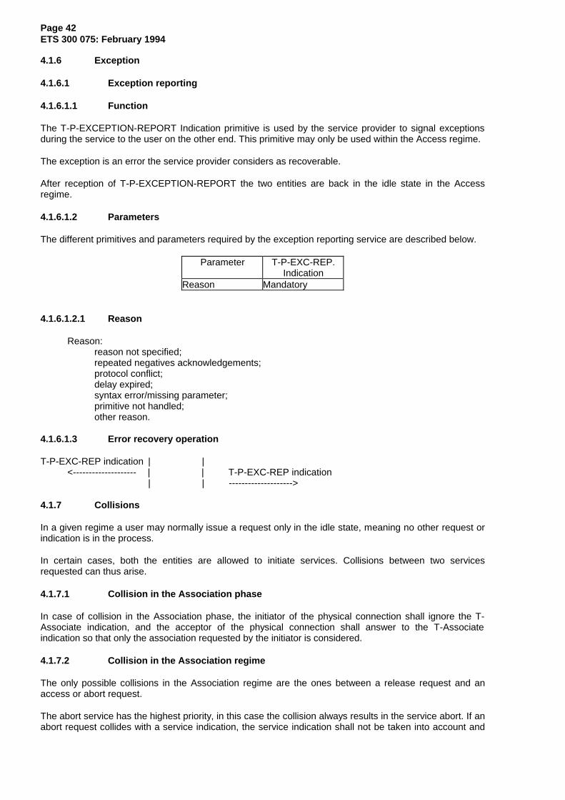
Page 42ETS 300 075: February 1994
4.1.6 Exception
4.1.6.1 Exception reporting
4.1.6.1.1 Function
The T-P-EXCEPTION-REPORT Indication primitive is used by the service provider to signal exceptionsduring the service to the user on the other end. This primitive may only be used within the Access regime.
The exception is an error the service provider considers as recoverable.
After reception of T-P-EXCEPTION-REPORT the two entities are back in the idle state in the Accessregime.
4.1.6.1.2 Parameters
The different primitives and parameters required by the exception reporting service are described below.
Parameter T-P-EXC-REP.Indication
Reason Mandatory
4.1.6.1.2.1 Reason
Reason:reason not specified;repeated negatives acknowledgements;protocol conflict;delay expired;syntax error/missing parameter;primitive not handled;other reason.
4.1.6.1.3 Error recovery operation
T-P-EXC-REP indication | |<-------------------- | | T-P-EXC-REP indication
| | -------------------->
4.1.7 Collisions
In a given regime a user may normally issue a request only in the idle state, meaning no other request orindication is in the process.
In certain cases, both the entities are allowed to initiate services. Collisions between two servicesrequested can thus arise.
4.1.7.1 Collision in the Association phase
In case of collision in the Association phase, the initiator of the physical connection shall ignore the T-Associate indication, and the acceptor of the physical connection shall answer to the T-Associateindication so that only the association requested by the initiator is considered.
4.1.7.2 Collision in the Association regime
The only possible collisions in the Association regime are the ones between a release request and anaccess or abort request.
The abort service has the highest priority, in this case the collision always results in the service abort. If anabort request collides with a service indication, the service indication shall not be taken into account and

Page 43ETS 300 075: February 1994
the abort request shall be carried out. If an abort indication collides with a service request, the servicerequest shall be ignored and the abort indication shall be carried out.
The release service has priority on an access request; in case a collision occurs it shall result in anassociation termination.
If a release request collides with an access service indication, the service indication shall not be taken intoaccount and the release request shall be carried out. If a release indication collides with an access servicerequest, the access service request shall be ignored and the release indication shall be carried out.
If a release request collides with a release indication, the release indication of the Master shall be carriedout and the other one shall be ignored.
4.1.7.3 Collision in the Access regime
In the Access regime a certain number of collisions between service requests may occur, these collisionsare solved in the following way:
Figure 5 specifies the result of collisions in the Access regime.
MasterSlave
ABORT END-ACCESS DLSRD TYPED-DATA P-EXC-REP
ABORT Abort Abort Abort Abort AbortEND-ACCESS Abort End-Access(1) End-Access End-Access End-AccessTYPED-DATA Abort End-Access (2) (3) (3)P-EXC-REP Abort End-Access (2) (3) (4)
ABORT = T-U-ABORT, T-P-ABORT,END-ACCESS = T-END-ACCESS,DLSRD = T-DIRECTORY, T-LOAD, T-SAVE, T-RENAME, T-DELETE,T-TYPED-DATA = T-TYPED-DATA,P-EXC-REP = T-P-EXC-REP.
Collision result:
Abort: the abort request is fulfilled. The association is terminated, data may be lost.
End-access: the end-access request is fulfilled. The Access regime is terminated. The otherservice is ignored or given up.
(1): The Master's end-access request is fulfilled. The Slave's request is ignored or given up.(2): The Slave's request is fulfilled. The Master's request is confirmed normally by the Slave. The
T-TYPED-DATA primitive has no consequence on the service.(3): The two requests are fulfilled.(4): No collision, back to the idle state in the Access regime.
Figure 5: Collision in the Access regime
4.1.7.4 Collision in the Transfer regime
During the transfer phase, the priority order is the following: first the abort service then, the user'sexception report service and the provider's exception report service.
Whenever the service provider issues a T-P-ABORT Indication or a T-P-EXCEPTION REPORT Indicationit shall give up the current service and go back to the idle state, as before the Association regimeestablishment or in the idle state in the Access regime.
Whenever the service provider receives a T-U-ABORT Request or a T-U-ABORT Indication, it shall giveup the current service and fulfil the user's abort service, and goes back to the idle state, as before theassociation regime establishment.
Whenever a transfer request and a abort transfer request collide, the abort transfer request is fulfilled, andall the transfer primitives in the process are given up.

Page 44ETS 300 075: February 1994
5 Telesoftware and auxiliary device applications
5.1 Preliminaries
Two applications are hereby defined: telesoftware and auxiliary device.
Through a network, a telesoftware application allows interconnection of two machines and thus allows fileexchange.
The telesoftware and auxiliary device application are defined by rules specifying the use of the service andby a file structure which contains the characteristics of each transfer file and the relationship of thesecharacteristics to the actions performed by the applications which manipulate these files.
A transfer file structure is composed of a set of informations containing:
– unique file name, that allows it to be referenced without ambiguity;– descriptive file attributes which express characteristics of the file (date...);– attributes describing the logical structure and the data stored in the file;– data, forming the content of the file.
The first three kinds of information constitute the header of the file, and the data constitute the content ofthe file.
To be able to use the file transfer service, a practical implementation shall state the relationship betweenthe elements in the transferred file and the real storage system available.
In this application the files have been divided up in three different groups.
In the symmetrical service, the application does not make any assumption about the two machines andtheir functioning. This application may be used between two Servers, or two Executors, or between aServer and an Executor. Either entity may take the part of the Master depending on its requirements byredefining an Access regime within a given Association regime.
5.2 The telesoftware application organisation
The telesoftware application uses files described in subclause 5.5 and these files are transferredaccording to the rules described in subclause 5.6.
The telesoftware organisation allows file exchange from the three different groups:
– group of transferable files (group A);– group of application presentation files (group B);– group of service support files (group C).
NOTE: When using the service class "basic kernel" only group A files are considered. In thesymmetrical service class, the default group is group A and other groups may not beimplemented in some data bases.
5.2.1 Transferable files - group A
This group contains transferable files consisting of description, text, software, data and command fileswhich together make up the application (see subclause 5.4).
These files can be obtained by their transfer name. The list of all transfer names make up the file'sdirectory. The sublist of all transfer names of structure files make up the application's directory.
5.2.2 Application presentation file - group B
This group contains files describing the applications. If these files exist, they shall share the same transfername as the corresponding description file (name of the application). The list of all the transfer names ofapplication presentation files make up the application presentation file's directory.

Page 45ETS 300 075: February 1994
These files are text files. They carry technical, user and managerial information on the application sharingthe same name. The aim of these files is to provide the maximum of information on the application inorder to better guide the user.
5.2.3 Service support - group C
This group contains files for general information. This information is organised by use of files and isaccessible using key words. The list of all the transfer names of the service support files make up theservice support file's directory.
These files are text files. They carry general information on the service.
5.2.4 Working area
Several working areas are possible. It is up to the higher level application to define the different workingareas. These applications shall be able to offer access to a public and a private working area. The accessrights to these working areas may depend on different criteria (e.g. password).
However, access to one or the other working areas should be left transparent for the operator.
5.3 Printer application organisation
The printer device application is a specific case of the auxiliary device application. It uses files asdescribed in subclause 5.5. These files are transferred according to the rules described in subclause 5.6.All the file parameters are not used for the printer device application (see subclause 5.5.1.17).
5.4 Files
5.4.1 File identification
5.4.1.1 Preliminaries
In telesoftware, there are five types of files:
– Description Files (DeF);– Software Files (SF);– Data Files (DF);– Command Files (CF);– Text Files (TF).
The following subclauses indicate how these different files are regrouped in the three groups previouslydefined.
5.4.1.2 Description files
These files belong to group A. They carry data required to transfer the application, and also the names ofall the files which are part of this application.
5.4.1.3 Software file
These files belong to group A. They carry software to be executed immediately or after processing.
5.4.1.4 Data files
These files belong to group A. They carry information required by software files at execution time.
5.4.1.5 Command files
These files belong to group A. They carry processing indications meaningful for the entity which requiredtransfer of these files. These indications are to be applied on files which are part of the application. Theprocessing is done before or during execution of these files.
Page 46ETS 300 075: February 1994
5.4.1.6 Text files
These files may belong to group A, B or C. These files may be created upon a directory request on groupA, B or C.
5.4.1.6.1 Text files - group A
These files can be displayed and represent a user's manual or some data displayed during the executionof the application.
5.4.1.6.2 Text files - group B
These files carry displayable data. This data can be useful, before requiring transfer of the correspondingapplication.
5.4.1.6.3 Text files - group C
These files carry displayable data of the telesoftware support service.
This information is not necessarily related to the transferable applications.
5.4.1.6.4 Text files from a file directory request
These files list all the file names belonging to the set of files where the request took place. The length ofthis list depends on the parameter designation in the file directory request.
5.4.2 Transferable applications
A transferable application is a set of files. These files are part of the group A and their number is notlimited.
5.4.2.1 Structure of a transferable application
A transferable application is made up of a description file and at least one software, command, data ortext file.
5.4.2.1.1 Purpose of the description file
The purpose of the description file is to provide coded information re-grouping the characteristics of atransferable application and the list of all files which are part of this application.
5.4.2.1.2 Organisation of the description file
Like all other files, the description file is made up of a header and of a main body.
The header is described in subclause 5.5.1.
The main body regroups all the headers of all the files which are part of this application.
The data in these headers are regrouped in each file.
This data provide useful elements needed to perform correctly the transfer of an application, for instance:type, transfer name, size, resources, coding. Other data fields can be found.
5.4.3 File classification
The files are classified into three groups.
Inside each group, the files have a unique transfer name. This name is kept in a directory. It points to anapplication whenever it is the name of a description file, and to a file in all other cases.
Page 47ETS 300 075: February 1994
5.4.3.1 Structure of a transfer name
A transfer name is made up of one or more keywords. The maximum number of keywords in a name iseight (8).
These keywords are called subnames of the transfer name.
5.4.3.1.1 Keywords
A keyword is a byte sequence of no more than 12 bytes. Each byte can take different values.
5.4.3.1.2 Transfer name
If a transfer name is made up of several keywords, then they are separated by a byte "/". The maximumlength of a transfer name, counting all separators, is 70.
5.5 Description of the transfer file structure
A transfer l file is structured as follows:
a) the file’s attributes - the header;b) the data in the file - the file’s content.
This organisation is valid for an application:
a) telesoftware;b) printing;c) telesoftware and printing.
5.5.1 Header
The header provides information on the characteristics of the file. It is always transmitted in the first T-WRITE (or T-WRITE-END for short files) and possibly in the following ones if necessary, in order to linkthe header information to the data. The file content may be transmitted in the first T-WRITE (if its datafield is not filled up with the file header), and subsequently in other T-WRITE or T-WRITE-END.
The attributes given in subclauses 5.5.1.1 to 5.5.1.28 may be used.
5.5.1.1 File type
There are five different types of file:
– the description file which identifies the characteristics of the files which compound the application;– the software files to be executed;– the data files;– the command files;– the text files to be displayed or printed.
The default value is text file.
5.5.1.2 Execution order
This attribute indicates whether the application shall be executed immediately or after the association tothe telesoftware application has been released. It also indicates the starting file of the application (defaultvalue: don't care).
5.5.1.3 Transfer name
This attribute represents the designation of the file on the sender's side (see subclause 5.4.3.1).
Page 48ETS 300 075: February 1994
5.5.1.4 Filename
This attribute provides a "name" which may be associated with the transferred file in the filestore (thefilename is not necessarily related to any transfer name).
NOTE: Some systems may require that the first 6 characters of the filename should bealphabetic or numeric. Drive, device or directory designations should not be included inthis attribute, but file-type suffices may be included.
5.5.1.5 Date/time of last modification
This attribute indicates the date and time of the last modification of the file.
5.5.1.6 File length
This attribute indicates the size in bytes of the file content in uncompressed form.
5.5.1.7 Destination code
This attribute may take the values "don't care" (default), "foreground memory", "background memoryrandom access required" (e.g. disk) or "cassette tape required".
NOTE: The latter option may be required for some software to overcome operating system orsecurity constraints.
5.5.1.8 File coding
This attribute indicates the data syntax, the language, the machine type or the operating system.
According to the file type, this attribute may take the following values:
– software file:source code in a text form;source code in a tokenised form;intermediate code;object code;executable code (default value);
– Data file:binary code (default value);character code;
– Command file:dependant machine code (default value);standardised code;
– Text file:character code (default value);Videotex code (+ profile);other code.
Additional information, if present, identify by means of a text string a language (such as "BASIC", "P-CODE") or a target processor (such as "6502"). This may optionally be followed by an identification of thelanguage dialect (such as "MSDOS").
5.5.1.9 Destination name
This attribute indicates a drive, device and/or directory name for the storage of the file. It may not be usedin combination with a destination code. The length of the attribute is limited to 255 bytes.

Page 49ETS 300 075: February 1994
5.5.1.10 Cost
This attribute represents the price of the software, it is a string of no more than 31 bytes. The content ofthis field is only for information.
5.5.1.11 User field
This field is used to carry comments related to the file or to the relevant application and consisting of nomore than 254 displayable characters.
5.5.1.12 Load address
This attribute may be used to indicate an address in foreground memory at which the data shall be loaded.In the case of a transfer to foreground memory, this attribute provides a base address for the transferreddata, in the case of transfer to background memory, this attribute may be recorded as a file attributeaccording to the terminal filing's system. The relationship of this address to any executor operating systemvirtual memory addressing scheme is not specified by this ETS.
5.5.1.13 Execute address (absolute)
This attribute may be used to indicate an absolute address at which programme execution shall startwhen the file is loaded into foreground memory. The relationship of this address to any executor operatingsystem virtual memory addressing scheme is not specified by this ETS.
5.5.1.14 Execute address (relative)
This attribute may be used to indicate an address relative to the beginning of the file at which programmeexecution shall start when the file has been loaded into foreground memory,
5.5.1.15 Compression mode
This attribute is used to indicate which compression algorithm is used for the file's content.
This attribute may take one of the following values:
- basic compression mode;- high efficiency compression mode;- "application defined" compression mode.
NOTE: A compression algorithm is given in Annex A in order to provide interoperability.
5.5.1.16 Device
This attribute is used to specify the characteristics of the device to which a file content is to be sent.
NOTE: Only the printer is taken into account in the basic kernel.
5.5.1.17 File checksum
This attribute contains the 32-bit "Frame Check Sequence" (FCS) calculated from the uncompressed filecontent.
5.5.1.18 Author name
This attribute indicates the name of the creator of the file.
5.5.1.19 Future file length
This attribute indicates the nominal length to which the file may grow as a result of an extension.
Page 50ETS 300 075: February 1994
5.5.1.20 Permitted actions
This attribute indicates the set of actions that can be performed on the file (read, insert, replace, erase).
5.5.1.21 Legal qualification
This attribute conveys information about the status and use of the file.
5.5.1.22 Creation
This attribute indicates the date and time of the creation of the file.
5.5.1.23 Last read access
This attribute indicates the date and time of the last reading of the file.
5.5.1.24 Identity of the last modifier
This attribute indicates the name of the last modifier of the file. It is altered by the receiver whenever thefile has been opened for modification or extension and is closed.
5.5.1.25 Identity of the last reader
This attribute indicates the name of the last reader of the file. It is altered by the receiver whenever the filehas been opened for reading and is closed.
5.5.1.26 Recipient
This attribute indicates the name of the receiver of the file.
5.5.1.27 Telematic file transfer version
This attribute indicates the telematic file transfer method version being used (ETS number and date).
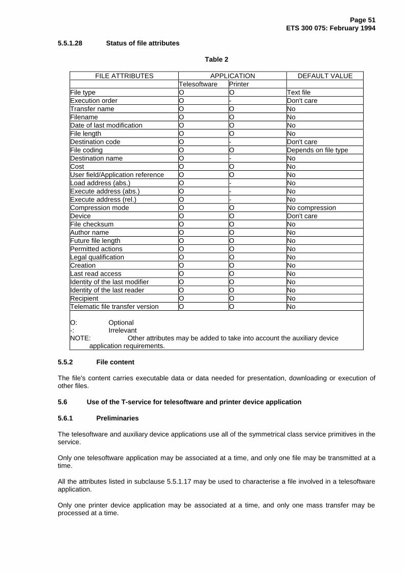
Page 51ETS 300 075: February 1994
5.5.1.28 Status of file attributes
Table 2
FILE ATTRIBUTES APPLICATION DEFAULT VALUETelesoftware Printer
File type O O Text fileExecution order O - Don't careTransfer name O O NoFilename O O NoDate of last modification O O NoFile length O O NoDestination code O - Don't careFile coding O O Depends on file typeDestination name O - NoCost O O NoUser field/Application reference O O NoLoad address (abs.) O - NoExecute address (abs.) O - NoExecute address (rel.) O - NoCompression mode O O No compressionDevice O O Don't careFile checksum O O NoAuthor name O O NoFuture file length O O NoPermitted actions O O NoLegal qualification O O NoCreation O O NoLast read access O O NoIdentity of the last modifier O O NoIdentity of the last reader O O NoRecipient O O NoTelematic file transfer version O O No
O: Optional-: IrrelevantNOTE: Other attributes may be added to take into account the auxiliary device
application requirements.
5.5.2 File content
The file's content carries executable data or data needed for presentation, downloading or execution ofother files.
5.6 Use of the T-service for telesoftware and printer device application
5.6.1 Preliminaries
The telesoftware and auxiliary device applications use all of the symmetrical class service primitives in theservice.
Only one telesoftware application may be associated at a time, and only one file may be transmitted at atime.
All the attributes listed in subclause 5.5.1.17 may be used to characterise a file involved in a telesoftwareapplication.
Only one printer device application may be associated at a time, and only one mass transfer may beprocessed at a time.
Page 52ETS 300 075: February 1994
The attributes listed in subclause 5.5.1.17 may be used to characterise a file involved in a printer deviceapplication.
For telesoftware applications consisting in several files, a description file may be transmitted first. This fileconsists of its own header and contains all the headers of the files to be downloaded. Each header is self-delimited by Type Length Value (TLV) encoding. When transmitting the subsequent files, the transmittedheaders may not include information which was included in the description file.
This organisation allows for using the Telesoftware Data Unit (TDU) service for other file transferapplications than telesoftware which would require a different file organisation (e.g. a specific applicationdescriptor which would be different from the description file).
5.6.2 Association
The purpose of the association is to establish a link between two applications.
The association uses the T-ASSOCIATE Request and the T-ASSOCIATE Response services primitives.
The application name shall carry:
!T telesoftware;!P printer's application;!A telesoftware and printer's application.
If !T is used as an application name, only telesoftware files may be transferred during the association.
If !P is used as an application name, only printer device files may be transferred during the association.
If !A is used, printer device and telesoftware files may be transferred during the association.
If the selected service class is "basic kernel", the restriction on the T-service apply and the access, endaccess, file directory, load, save help, rename, delete and typed data services are not available.
5.6.3 Release
The release of the application is performed by the T-RELEASE Request and T-RELEASE Responseservice primitives.
5.6.4 Abort
The abort service is used to leave an application in an abnormal way.
The T-U-ABORT Request primitive may be used by the application.
The parameter Reason in the Request/Indication indicates the reason for the abort.
5.6.5 Access
The transfer conditions are established by use of the T-ACCESS Request and T-ACCESS Responseservice primitives.
If the role is Slave, the parameter User data indicates the scope of services like T-DIRECTORY,T-LOAD, T-SAVE, T-RENAME, T-DELETE on the groups A, B and C.
If the role is Master, the parameter User data is not used.
5.6.6 End of access
Terminating an Access regime is performed by the T-END-ACCESS Request and T-END-ACCESSResponse service primitives.
Page 53ETS 300 075: February 1994
5.6.7 File directory
The T-DIRECTORY Request primitive is used by the Master to request transfer of files, collection of filenames and application name, from the Slave to the Master. In case the request is accepted, the filecontent shall depend on the designation parameter in the request.
A directory request is performed by the T-DIRECTORY Request primitive.
The parameter Designation is a byte sequence indicating the criterias for selecting the file names.
The parameter User data indicates the group or subgroup on which applies the directory request.
The response/confirmation is provided by the parameter Result in the T-DIRECTORY Response primitive,this parameter indicates acceptance or the reason for the refusal.
Acceptance means that file or application names meet with the criteria in the request.
The Slave shall then carry on with the transfer of the file listing all the file or application names fulfilling therequest.
5.6.7.1 Byte sequence in a directory request
The designation parameter in a directory request is made of one or more elementary words separated bya specific operator. Other operators as OR, AND, or specific codes as parenthesis or star can be used. Adetailed description of the syntax is given in subclause 5.7.
The maximum number of elementary words is 8.
5.6.8 Load
The load request is performed by the T-LOAD Request service primitive. This primitive is used by theMaster to request file transfer from the Slave to the Master.
The designation parameter contains the file transfer name requested (see subclause 5.4.3.1).
The recovery parameter if it is present (provided it was previously allowed) indicates the number of thelast T-WRITE correctly received. Recovery shall start with the following number.
The user data parameter indicates the group required in the LOAD service. If this parameter is absent thegroup is meant to be the A group.
The response/confirmation is provided by the parameter Result in the T-LOAD Response primitive, thisparameter indicates acceptance or the reason for the refusal.
Acceptance means that a file meets the request.
The Slave shall then carry on with the transfer of the file.
5.6.9 Help
Request of a help file can be performed by the T-LOAD Request service primitive on the group A, thevalue of the designation parameter is then 2/0.
The recovery parameter, if it is present (provided it was previously allowed), indicates the number of thelast T-WRITE correctly received. Recovery shall start with the following number.
The response/confirmation is provided by the parameter Result in the T-LOAD Response primitive, thisparameter indicates acceptance or the reason for the refusal.
Acceptance means that a file meets the request.
The Slave shall then carry on with the transfer of the file.

Page 54ETS 300 075: February 1994
The purpose of this file is to provide informations on the organisation of the Slave's data base: structure,key words, file name...
This file is a text file coded characters.
5.6.10 Save
In the basic kernel, the Master may request transfer from Master to Slave by initiating a mass transferusing T-WRITE.
In the symmetrical service, the T-SAVE Request primitive is used by the Master to request file transferfrom the Master to the Slave.
In the telesoftware service, one can transfer files from any of the A, B or C groups (see subclause 5.2).
The designation parameter contains the file transfer name requested (see subclause 5.4.3.1).
The recovery parameter if it is present (provided it was previously allowed) indicates the number of thelast T-WRITE correctly received. Recovery shall start with the following number.
The user data parameter indicates the group required in the SAVE service. If this parameter is absent thegroup is meant to be the A group.
The response/confirmation is provided by the parameter Result in the T-SAVE Response primitive, thisparameter indicates acceptance or the reason for the refusal.
Acceptance means that a file meets the request.
The Master shall then carry on with the transfer of the file.
5.6.11 Rename
The T-RENAME Request primitive is used by the Master to request renaming of a file or applicationtransfer name in the Slave's data base.
The designation and new name parameters contain the old and new file's (or application) transfer name.
The user data parameter indicates the group required in the RENAME service. If this parameter is absentthe group is meant to be the A group.
The response/confirmation is provided by the parameter Result in the T-RENAME Response primitive,this parameter indicates acceptance or the reason for the refusal.
Acceptance means that a file was renamed.
Refusal indicates that the renaming was not performed.
5.6.12 Suppression
The T-DELETE Request primitive is used by the Master to request the suppression of a file or applicationtransfer name in the Slave's data base.
The designation parameter indicates the file to be deleted.
The user data parameter indicates the group required in the DELETE service. If this parameter is absentthe group is meant to be the A group.
The response/confirmation is provided by the parameter Result in the T-DELETE Response primitive, thisparameter indicates acceptance or the reason for the refusal.
Acceptance means that a file was deleted.
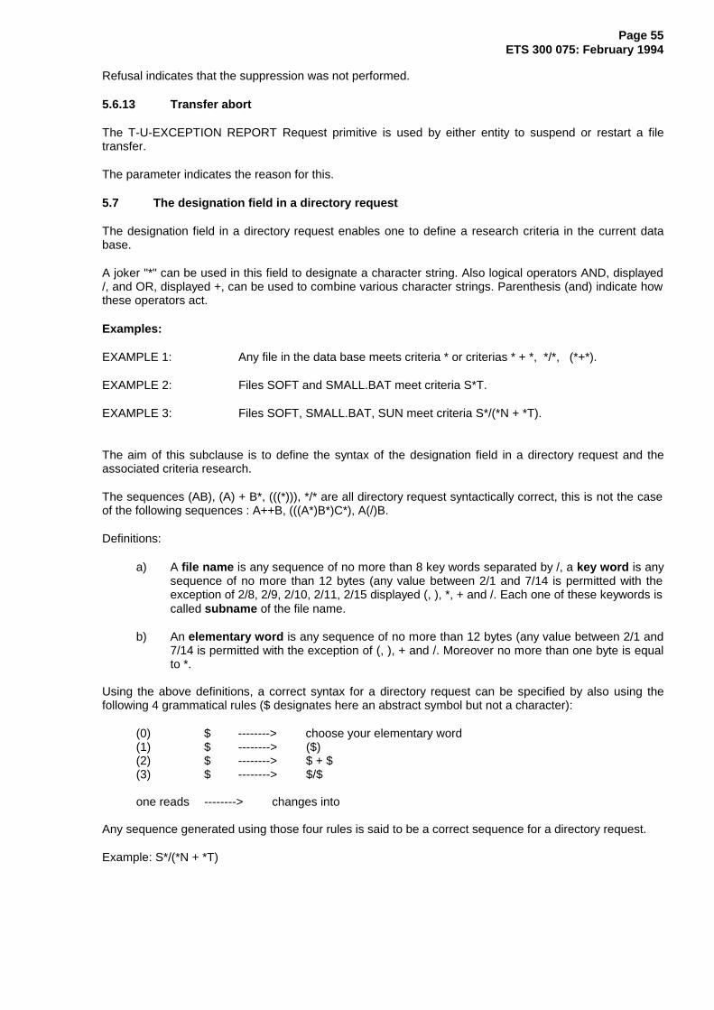
Page 55ETS 300 075: February 1994
Refusal indicates that the suppression was not performed.
5.6.13 Transfer abort
The T-U-EXCEPTION REPORT Request primitive is used by either entity to suspend or restart a filetransfer.
The parameter indicates the reason for this.
5.7 The designation field in a directory request
The designation field in a directory request enables one to define a research criteria in the current database.
A joker "*" can be used in this field to designate a character string. Also logical operators AND, displayed/, and OR, displayed +, can be used to combine various character strings. Parenthesis (and) indicate howthese operators act.
Examples:
EXAMPLE 1: Any file in the data base meets criteria * or criterias * + *, */*, (*+*).
EXAMPLE 2: Files SOFT and SMALL.BAT meet criteria S*T.
EXAMPLE 3: Files SOFT, SMALL.BAT, SUN meet criteria S*/(*N + *T).
The aim of this subclause is to define the syntax of the designation field in a directory request and theassociated criteria research.
The sequences (AB), (A) + B*, (((*))), */* are all directory request syntactically correct, this is not the caseof the following sequences : A++B, (((A*)B*)C*), A(/)B.
Definitions:
a) A file name is any sequence of no more than 8 key words separated by /, a key word is anysequence of no more than 12 bytes (any value between 2/1 and 7/14 is permitted with theexception of 2/8, 2/9, 2/10, 2/11, 2/15 displayed (, ), *, + and /. Each one of these keywords iscalled subname of the file name.
b) An elementary word is any sequence of no more than 12 bytes (any value between 2/1 and7/14 is permitted with the exception of (, ), + and /. Moreover no more than one byte is equalto *.
Using the above definitions, a correct syntax for a directory request can be specified by also using thefollowing 4 grammatical rules ($ designates here an abstract symbol but not a character):
(0) $ --------> choose your elementary word(1) $ --------> ($)(2) $ --------> $ + $(3) $ --------> $/$
one reads --------> changes into
Any sequence generated using those four rules is said to be a correct sequence for a directory request.
Example: S*/(*N + *T)
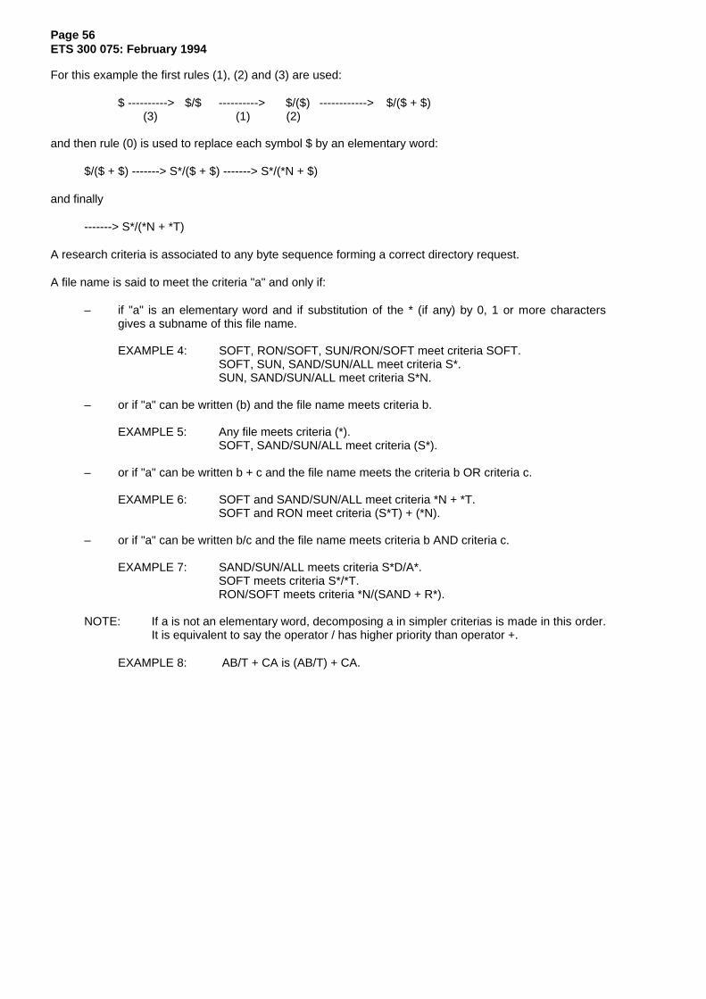
Page 56ETS 300 075: February 1994
For this example the first rules (1), (2) and (3) are used:
$ ----------> $/$ ----------> $/($) ------------> $/($ + $)(3) (1) (2)
and then rule (0) is used to replace each symbol $ by an elementary word:
$/($ + $) -------> S*/($ + $) -------> S*/(*N + $)
and finally
-------> S*/(*N + *T)
A research criteria is associated to any byte sequence forming a correct directory request.
A file name is said to meet the criteria "a" and only if:
– if "a" is an elementary word and if substitution of the * (if any) by 0, 1 or more charactersgives a subname of this file name.
EXAMPLE 4: SOFT, RON/SOFT, SUN/RON/SOFT meet criteria SOFT.SOFT, SUN, SAND/SUN/ALL meet criteria S*.SUN, SAND/SUN/ALL meet criteria S*N.
– or if "a" can be written (b) and the file name meets criteria b.
EXAMPLE 5: Any file meets criteria (*).SOFT, SAND/SUN/ALL meet criteria (S*).
– or if "a" can be written b + c and the file name meets the criteria b OR criteria c.
EXAMPLE 6: SOFT and SAND/SUN/ALL meet criteria *N + *T.SOFT and RON meet criteria (S*T) + (*N).
– or if "a" can be written b/c and the file name meets criteria b AND criteria c.
EXAMPLE 7: SAND/SUN/ALL meets criteria S*D/A*.SOFT meets criteria S*/*T.RON/SOFT meets criteria *N/(SAND + R*).
NOTE: If a is not an elementary word, decomposing a in simpler criterias is made in this order.It is equivalent to say the operator / has higher priority than operator +.
EXAMPLE 8: AB/T + CA is (AB/T) + CA.

Page 57ETS 300 075: February 1994
6 T-Protocol specification
6.1 Overview
Table 3 gives an overview of TDUs and their mapping on the service primitives. This table indicates whichTDU shall be sent for a given service primitive and which TDUs may be received in response to that TDU.However, this table is not exhaustive and does not deal with collisions nor with the complete error handlingmechanism.
Table 3: List of the TDUs used
Issued Receivedservice TDU Possible response serviceprimitive TDU primitiveT-ASSOCIATE T-Associaterequest T-Response-positive (S) T-ASSOCIATE conf(+)
T-Response-negative (S) T-ASSOCIATE conf(-)T-Abort (A) T-U/P-ABORT.ind
T-RELEASE T-Releaserequest T-Response-positive (S) T-RELEASE conf(+)
T-Abort (A) T-U/P-ABORT indT-U-ABORT T-Abortrequest No response is requiredT-ACCESS T-Accessrequest T-Response-positive (S) T-ACCESS conf(+)
T-Response-negative (S) T-ACCESS conf(-)T-Abort (A) T-U/P-ABORT ind
T-END- T-End-AccessACCESS.req T-Response-positive (S) T-END-ACCESS conf(+)
T-Abort (A) T-U/P-ABORT indT-DIRECTORY T-Directoryrequest T-Response-positive (S) T-DIRECTORY conf(+)
T-Response-negative (S) T-DIRECTORY conf(-)T-P-Exception (A) T-P-EXCEPTION indT-Abort (A) T-U/P-ABORT ind
T-LOAD T-Loadrequest T-Response-positive (S) T-LOAD.conf(+)
T-Response-negative (S) T-LOAD.conf(-)T-P-Exception (A) T-P-EXCEPTION indT-Abort (A) T-U/P-ABORT ind
(continued)
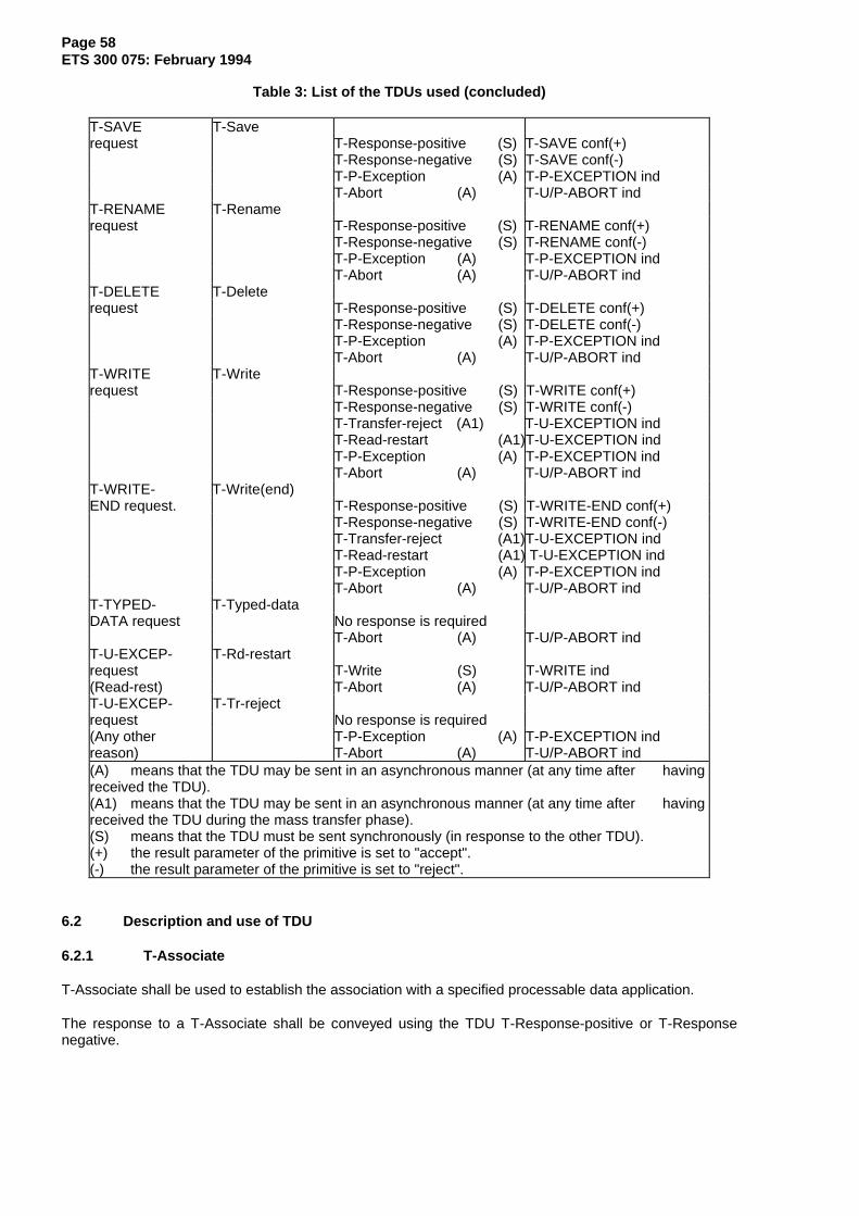
Page 58ETS 300 075: February 1994
Table 3: List of the TDUs used (concluded)
T-SAVE T-Saverequest T-Response-positive (S) T-SAVE conf(+)
T-Response-negative (S) T-SAVE conf(-)T-P-Exception (A) T-P-EXCEPTION indT-Abort (A) T-U/P-ABORT ind
T-RENAME T-Renamerequest T-Response-positive (S) T-RENAME conf(+)
T-Response-negative (S) T-RENAME conf(-)T-P-Exception (A) T-P-EXCEPTION indT-Abort (A) T-U/P-ABORT ind
T-DELETE T-Deleterequest T-Response-positive (S) T-DELETE conf(+)
T-Response-negative (S) T-DELETE conf(-)T-P-Exception (A) T-P-EXCEPTION indT-Abort (A) T-U/P-ABORT ind
T-WRITE T-Writerequest T-Response-positive (S) T-WRITE conf(+)
T-Response-negative (S) T-WRITE conf(-)T-Transfer-reject (A1) T-U-EXCEPTION indT-Read-restart (A1)T-U-EXCEPTION indT-P-Exception (A) T-P-EXCEPTION indT-Abort (A) T-U/P-ABORT ind
T-WRITE- T-Write(end)END request. T-Response-positive (S) T-WRITE-END conf(+)
T-Response-negative (S) T-WRITE-END conf(-)T-Transfer-reject (A1)T-U-EXCEPTION indT-Read-restart (A1) T-U-EXCEPTION indT-P-Exception (A) T-P-EXCEPTION indT-Abort (A) T-U/P-ABORT ind
T-TYPED- T-Typed-dataDATA request No response is required
T-Abort (A) T-U/P-ABORT indT-U-EXCEP- T-Rd-restartrequest T-Write (S) T-WRITE ind(Read-rest) T-Abort (A) T-U/P-ABORT indT-U-EXCEP- T-Tr-rejectrequest No response is required(Any otherreason)
T-P-Exception (A)T-Abort (A)
T-P-EXCEPTION indT-U/P-ABORT ind
(A) means that the TDU may be sent in an asynchronous manner (at any time after havingreceived the TDU).(A1) means that the TDU may be sent in an asynchronous manner (at any time after havingreceived the TDU during the mass transfer phase).(S) means that the TDU must be sent synchronously (in response to the other TDU).(+) the result parameter of the primitive is set to "accept".(-) the result parameter of the primitive is set to "reject".
6.2 Description and use of TDU
6.2.1 T-Associate
T-Associate shall be used to establish the association with a specified processable data application.
The response to a T-Associate shall be conveyed using the TDU T-Response-positive or T-Responsenegative.
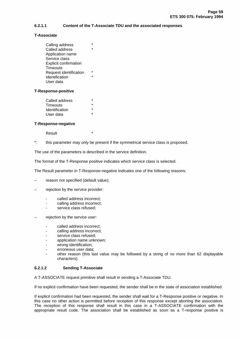
Page 59ETS 300 075: February 1994
6.2.1.1 Content of the T-Associate TDU and the associated responses
T-Associate
Calling address *Called address *Application nameService classExplicit confirmationTimeoutsRequest identification *Identification *User data
T-Response-positive
Called address *Timeouts *Identification *User data *
T-Response-negative
Result *
*: this parameter may only be present if the symmetrical service class is proposed.
The use of the parameters is described in the service definition.
The format of the T-Response positive indicates which service class is selected.
The Result parameter in T-Response-negative indicates one of the following reasons:
– reason not specified (default value);
– rejection by the service provider:
- called address incorrect;- calling address incorrect;- service class refused;
– rejection by the service user:
- called address incorrect;- calling address incorrect;- service class refused;- application name unknown;- wrong identification;- erroneous user data;- other reason (this last value may be followed by a string of no more than 62 displayable
characters).
6.2.1.2 Sending T-Associate
A T-ASSOCIATE request primitive shall result in sending a T-Associate TDU.
If no explicit confirmation have been requested, the sender shall be in the state of association established.
If explicit confirmation had been requested, the sender shall wait for a T-Response positive or negative. Inthis case no other action is permitted before reception of this response except aborting the association.The reception of this response shall result in this case in a T-ASSOCIATE confirmation with theappropriate result code. The association shall be established as soon as a T-response positive is

Page 60ETS 300 075: February 1994
received. If a T-response-negative or a T-Abort is received, the association shall not be established and aD-U-Abort (or SBVTPD End when the DDU-layer is not used) shall be sent by the initiator.
NOTE: It is recommended that T-Abort is not used to reject a T-Associate for which an explicitconfirmation was requested.
If the symmetrical service class is proposed in T-Associate an explicit confirmation shall be requested.
6.2.1.3 Receiving T-Associate
A valid incoming T-Associate TDU shall result in a T-ASSOCIATE indication primitive.
If no explicit confirmation is requested, the association shall be established (it shall be rejected using T-Abort).
If explicit confirmation is requested, a T-ASSOCIATE response primitive shall result in sending aT-Response-positive or negative depending on the result parameter of the primitive. If a T-Response-positive is returned, the association shall be established, otherwise the association shall not beestablished.
6.2.2 T-Release
This TDU shall be used to request the orderly termination of the processable data application.
The response to a T-Release shall be conveyed using the TDU T-Response-positive.
6.2.2.1 Content of the T-Release TDU and the associated response
T-Release
User data
T-Response-positive
User data *
*: this parameter may only be present if the symmetrical service class has been selected.
The use of the parameters is described in the service definition.
6.2.2.2 Sending T-Release
A T-RELEASE request primitive shall result in a T-Release TDU. If the selected service class is "basickernel", only the initiator of the association is permitted to send a T-Release TDU. A T-Release TDU maybe sent at any time after the association has been established when no other regime is established.
No other action is permitted after having sent a T-Release TDU before having received a T-Response-positive TDU except aborting the association.
On reception of the T-Response-positive TDU a D-U-Abort (or SBVTPD End when the DDU-layer is notused) shall be sent. The reception of a T-Response-positive shall result in a T-RELEASE confirmation.
6.2.2.3 Receiving T-Release
A valid incoming T-Release TDU shall result in a T-RELEASE indication. A T-RELEASE confirmationprimitive shall result in sending a T-Response-positive to acknowledge the T-Release, a negativeresponse shall not be permitted.
6.2.3 T-Abort
This TDU shall be used to abruptly terminate the association.

Page 61ETS 300 075: February 1994
6.2.3.1 Content of the T-Abort TDU
T-Abort
Reason *
*: this parameter may only be present if the symmetrical service class has been selected.
The following values of the Reason parameter are related to the T-P-ABORT service:
– repeated negative acknowledgements/repeated errors;– delay expired;– unknown message;– protocol conflict;– unrecoverable lower layer error;– syntax error;– other reason (this last value may be followed by a string of no more than 62 displayable
characters).
The following values of the Reason parameter are related to the T-U-ABORT service:
– reason not specified (default value);– wrong identification;– erroneous role/function;– other reason (this last value may be followed by a string of no more than 62 displayable
characters).
6.2.3.2 Sending T-Abort
A T-U-ABORT request primitive or an exception condition (see subclauses 6.3.2 and 6.3.3) shall result insending a T-Abort TDU.
A T-Abort may be sent at any time after having received a T-Associate, to reject a non confirmedT-Associate or to abruptly terminate an association.
If the selected service class is basic kernel, only the acceptor of the association is permitted to send a T-Abort.
6.2.3.3 Receiving T-Abort
A valid incoming T-Abort TDU shall result in issuing a T-U-ABORT or T-P-ABORT indication primitive,depending on the reason parameter. The association shall be terminated.
A D-U-Abort DDU (or SBV TPD End when the DDU layer is not used) shall be sent on reception of a T-Abort TDU.
6.2.4 T-Access
T-Access shall be used to establish the Access regime. This TDU may only be used if the symmetricalservice class has been selected.

Page 62ETS 300 075: February 1994
The response to a T-Access shall be conveyed using the TDU T-Response-positive or T-Responsenegative.
6.2.4.1 Content of the T-Access TDU and the associated responses
T-Access
RoleFunctionsTransfer unit sizeAnticipation windowRecoveryTransfer ModeUser data
T-Response-positive
FunctionsTransfer unit sizeAnticipation windowRecoveryTransfer ModeUser data
T-Response-negative
Result
The use of the parameters is described in the service definition.
The Result parameter in T-Response-negative indicates one of the following reasons:
– reason not specified (default value);
– rejection by the service provider:
- role refused;
– rejection by the service user:
- role refused;- insufficient primitives handled;- erroneous user data;- other reason (this last value may be followed by a string of no more than 62 displayable
characters).
6.2.4.2 Sending T-Access
A T-ACCESS request primitive shall result in sending a T-Access TDU. Only the Master is permitted tosend a T-Access TDU when the Association regime is established and provided that no other regime isestablished. Then the sender shall wait for a T-Response positive or negative; no other action shall bepermitted before reception of this response except aborting the association. The reception of thisresponse shall result in a T-ACCESS confirmation with the appropriate result code. The Access regimeand the assigned role shall be established as soon as a T-Response positive is received. If a T-Response-negative or a T-Abort is received, the Access regime shall not be established.
6.2.4.3 Receiving T-Access
A valid incoming T-Access TDU shall result in a T-ACCESS indication primitive.
A T-ACCESS response primitive shall result in sending a T-Response-positive or negative depending onthe result parameter of the primitive. If a T-Response-positive is returned, the Access regime shall beestablished, otherwise the Access regime shall not be established.

Page 63ETS 300 075: February 1994
6.2.5 T-End-Access
T-End-Access shall be used to request the termination of the Access regime.
The response to a T-End-Access shall be conveyed using the TDU T-Response-positive.
6.2.5.1 Content of the T-End-Access TDU and the associated response
T-End-Access
ReasonUser data
T-Response-positive
User data
The use of the parameters is described in the service definition.
The Reason parameter in T-End-Access takes one of the following values:
– termination of the access regime requested by the service user:
- reason not specified (default value);- user abort of the access regime;- insufficient primitives handled;- other reason (this last value may be followed by a string of no more than 62 displayable
characters).
6.2.5.2 Sending T-End-Access
A T-END-ACCESS request primitive shall result in sending a T-End-Access TDU. A T-End-Access TDUmay be sent at any time after the Access regime has been established when no other embedded regimeis established.
No other action is permitted after having sent a T-End-Access TDU before having received a T-Responsepositive TDU except aborting the association. Upon reception of a T-Response-positive, both entities shallbe in an idle state with the association regime established.
6.2.5.3 Receiving T-End-Access
A valid incoming T-End-Access TDU shall result in a T-END-ACCESS indication. AT-END-ACCESS-confirmation primitive shall result in sending a T-Response-positive to acknowledge theT-End-Access, a negative response is not permitted.
6.2.6 T-Directory
T-Directory shall be used to request the transmission of a file directory from the Slave to the Master and toestablish a Transfer regime.
The response to a T-Directory shall be conveyed using the TDU T-Response-positive or T-Responsenegative.
6.2.6.1 Content of the T-Directory TDU and the associated responses
T-Directory
DesignationUser data
T-Response-positive

Page 64ETS 300 075: February 1994
T-Response-negative
Result
The use of the parameters is described in the service definition.
The Result parameter in T-Response-negative indicates one of the following reasons:
– rejection by the service user:
- reason not specified (default value);- erroneous designation;- no answer to the request;- erroneous user data;- other reason (this last value may be followed by a string of no more than 62 displayable
characters).
6.2.6.2 Sending T-Directory
A T-DIRECTORY request primitive shall result in sending a T-Directory TDU. Only the Master is permittedto send a T-Directory TDU when the Access regime is established and provided that no Transfer regime isestablished. The sender shall then wait for a T-Response positive or negative; no other action is permittedbefore reception of this response except aborting the association or reporting an exception. The receptionof this response shall result in a T-DIRECTORY confirmation with the appropriate result code. TheTransfer regime shall be established as soon as a T-Response positive is received. If a T-Response-negative, a T-P-Exception or a T-Abort is received, the Transfer regime shall not be established.
6.2.6.3 Receiving T-Directory
A valid incoming T-Directory TDU shall result in a T-DIRECTORY indication primitive.
A T-DIRECTORY response primitive shall result in sending a T-Response-positive or negative dependingon the result parameter of the primitive. If a T-Response-positive is returned, the Transfer regime shall beestablished, otherwise the Transfer regime shall not be established.
6.2.7 T-Load
T-Load shall be used to request the transmission of a file from the Slave to the Master and to establish aTransfer regime.
The response to a T-Load shall be conveyed using the TDU T-Response-positive or T-Responsenegative.
6.2.7.1 Content of the T-Load TDU and the associated responses
T-Load
Recovery pointDesignationUser data
T-Response-positive
T-Response-negative
Result
The use of the parameters is described in the service definition.

Page 65ETS 300 075: February 1994
The Result parameter in T-Response-negative indicates one of the following reasons:
– rejection by the service user:
- reason not specified (default value);- erroneous designation;- unknown file;- erroneous recovery point;- erroneous user data;- other reason (this last value may be followed by a string of no more than 62 displayable
characters).
6.2.7.2 Sending T-Load
A T-LOAD request primitive shall result in sending a T-Load TDU. Only the Master is permitted to send aT-Load TDU when the Access regime is established and provided that no Transfer regime is established.Then the sender shall wait for a T-Response positive or negative; no other action shall be permittedbefore reception of this response except aborting the association or reporting an exception. The receptionof this response shall result in a T-LOAD confirmation with the appropriate result code. The Transferregime shall be established as soon as a T-Response positive is received. If a T-Response-negative, a T-P-Exception or a T-Abort is received, the Transfer regime shall not be established.
6.2.7.3 Receiving T-Load
A valid incoming T-Load TDU shall result in a T-LOAD indication primitive.
A T-LOAD response primitive shall result in sending a T-Response-positive or negative depending on theresult parameter of the primitive. If a T-Response-positive is returned, the Transfer regime shall beestablished, otherwise the Transfer regime shall not be established.
6.2.8 T-Save
T-Save shall be used to announce the transmission of a file from the Master to the Slave and to establisha Transfer regime.
The response to a T-Save shall be conveyed using the TDU T-Response-positive or T-Responsenegative.
6.2.8.1 Content of the T-Save TDU and the associated responses
T-Save
recovery pointdesignationuser data
T-Response-positive
T-Response-negative
Result
The use of the parameters is described in the service definition.

Page 66ETS 300 075: February 1994
The Result parameter in T-Response-negative indicates one of the following reasons:
– rejection by the service user:
- reason not specified (default value);- erroneous designation;- already existing file;- erroneous recovery point;- erroneous user data;- other reason (this last value may be followed by a string of no more than 62 displayable
characters).
6.2.8.2 Sending T-Save
A T-SAVE request primitive shall result in sending a T-Save TDU. Only the Master is permitted to send aT-Save TDU when the Access regime is established and provided that no Transfer regime is established.Then the sender shall wait for a T-Response positive or negative; no other action is permitted beforereception of this response except aborting the association or reporting an exception. The reception of thisresponse shall result in a T-SAVE confirmation with the appropriate result code. The Transfer regime shallbe established as soon as a T-Response positive is received. If a T-Response-negative, a T-P-Exceptionor a T-Abort is received, the Transfer regime shall not be established.
6.2.8.3 Receiving T-Save
A valid incoming T-Save TDU shall result in a T-SAVE indication primitive.
A T-SAVE response primitive shall result in sending a T-Response-positive or negative depending on theresult parameter of the primitive. If a T-Response-positive is returned, the Transfer regime shall beestablished, otherwise the Transfer regime shall not be established.
6.2.9 T-Rename
T-Rename shall be used to change the designation of a file in the Slave's file system.
The response to a T-Rename shall be conveyed using the TDU T-Response-positive or T-Responsenegative.
6.2.9.1 Content of the T-Rename TDU and the associated responses
T-Rename
New nameDesignationUser data
T-Response-positive
T-Response-negative
Result
The use of the parameters is described in the service definition.

Page 67ETS 300 075: February 1994
The Result parameter in T-Response-negative indicates one of the following reasons:
– rejection by the service user:
- reason not specified (default value);- erroneous designation;- erroneous new name;- unknown file;- new name already in use;- erroneous user data;- other reason (this last value may be followed by a string of no more than 62 displayable
characters).
6.2.9.2 Sending T-Rename
A T-RENAME request primitive shall result in sending a T-Rename TDU. Only the Master is permitted tosend a T-Rename TDU when the Access regime is established and provided that no Transfer regime isestablished. Then the sender shall wait for a T-Response positive or negative; no other action is permittedbefore reception of this response except aborting the association or reporting an exception. The receptionof this response shall result in a T-RENAME confirmation with the appropriate result code.
6.2.9.3 Receiving T-Rename
A valid incoming T-Rename TDU shall result in a T-RENAME indication primitive.
A T-RENAME response primitive shall result in sending a T-Response-positive or negative depending onthe result parameter of the primitive.
6.2.10 T-Delete
T-Delete shall be used to request the deletion of a file in the Slave's file system.
The response to a T-Delete shall be conveyed using the TDU T-Response-positive or T-Responsenegative.
6.2.10.1 Content of the T-Delete TDU and the associated responses
T-Delete
DesignationUser data
T-Response-positive
T-Response-negative
Result
The use of the parameters is described in the service definition.
The Result parameter in T-Response-negative indicates one of the following reasons:
– rejection by the service user:
- reason not specified (default value);- erroneous designation;- unknown file;- erroneous user data;- other reason (this last value may be followed by a string of no more than 62 displayable
characters).
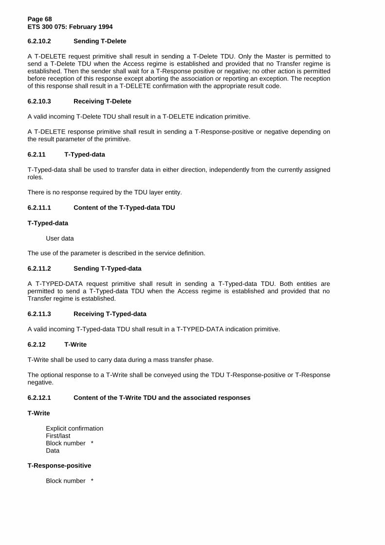
Page 68ETS 300 075: February 1994
6.2.10.2 Sending T-Delete
A T-DELETE request primitive shall result in sending a T-Delete TDU. Only the Master is permitted tosend a T-Delete TDU when the Access regime is established and provided that no Transfer regime isestablished. Then the sender shall wait for a T-Response positive or negative; no other action is permittedbefore reception of this response except aborting the association or reporting an exception. The receptionof this response shall result in a T-DELETE confirmation with the appropriate result code.
6.2.10.3 Receiving T-Delete
A valid incoming T-Delete TDU shall result in a T-DELETE indication primitive.
A T-DELETE response primitive shall result in sending a T-Response-positive or negative depending onthe result parameter of the primitive.
6.2.11 T-Typed-data
T-Typed-data shall be used to transfer data in either direction, independently from the currently assignedroles.
There is no response required by the TDU layer entity.
6.2.11.1 Content of the T-Typed-data TDU
T-Typed-data
User data
The use of the parameter is described in the service definition.
6.2.11.2 Sending T-Typed-data
A T-TYPED-DATA request primitive shall result in sending a T-Typed-data TDU. Both entities arepermitted to send a T-Typed-data TDU when the Access regime is established and provided that noTransfer regime is established.
6.2.11.3 Receiving T-Typed-data
A valid incoming T-Typed-data TDU shall result in a T-TYPED-DATA indication primitive.
6.2.12 T-Write
T-Write shall be used to carry data during a mass transfer phase.
The optional response to a T-Write shall be conveyed using the TDU T-Response-positive or T-Responsenegative.
6.2.12.1 Content of the T-Write TDU and the associated responses
T-Write
Explicit confirmationFirst/lastBlock number *Data
T-Response-positive
Block number *

Page 69ETS 300 075: February 1994
T-Response-negative
Block number *
6.2.12.1.1 First/last
This parameter indicates if the data transmitted in the T-Write TDU consist in the first block of data or thelast block or both or none.
This parameter shall be set to "first" when the parameter "first block" of the T-WRITE request orT-WRITE-END request primitive is set to "first".
This parameter shall be set to "last" when the TDU is issued subsequently to a T-WRITE-END requestprimitive.
6.2.12.1.2 Explicit confirmation
This parameter indicates whether or not a positive or negative confirmation is expected to the T-WriteTDU.
In the case of the last block of data or when the proposed anticipation window size is greater than 1 orwhen the recovery function is in use, the value shall be set to "explicit confirmation requested".
6.2.12.1.3 Block number
This parameter may only be present when the symmetrical service class has been selected. It shall bepresent when the proposed anticipation window size is greater than 1 or when the recovery has beenselected.
In T-Write this parameter indicates the number of the block, this number is increased by 1 at eachtransmission of a T-Write.
In T-Response-positive, this number indicates the block number of the acknowledged T-Write.
In T-Response-negative this number indicates the block number of the first T-Write to be retransmitted.
In T-Response positive or negative the block number parameter shall be present if and only if it waspresent in the corresponding T-Write.
6.2.12.1.4 Data
The T-Write TDU may contain a block of no more than 1024 octets of data if the Basic Kernel is used. Inthe symmetrical service the maximum size of a block shall be negotiated in the T-Access service.
6.2.12.2 Sending T-Write
A T-WRITE request or T-WRITE-END request primitive shall result in a T-Write TDU. This TDU shall besent in a D-Data DDU. Only the Sender is permitted to send a T-Write TDU in the following cases:
– in the idle state of the Association regime if the basic kernel service class has been selected;– in the idle state of the Access regime if the symmetrical service class has been selected and
the Basic Transfer mode has been selected;– after having sent a T-Response-positive to a T-Directory or T-Load TDU;– after having received a T-Response-positive to a T-Save TDU;– during a mass transfer phase.
If the basic kernel is being used or a window size of 1 is being used in the symmetrical service then, ifexplicit confirmation has been requested, the Sender shall wait for a T-Response-positive or negative, inthis case no other action is permitted before reception of this response except aborting the association orreporting an exception.
Page 70ETS 300 075: February 1994
If the window size is not equal to 1, then the sender may transmit up to the window size number of T-WRITE request or up to T-WRITE-END request before waiting for a T-Response except aborting theassociation or reporting an exception.
The reception of T-Response shall result in this case in a T-WRITE confirmation or T-WRITE-ENDconfirmation primitive with the appropriate result code.
In the case of T-Response negative on a T-Write which was not indicating "last block", the transfer shallbe resumed from the first T-Write sent after the last T-Write for which a T-Response-positive had beenreceived (or from the T-Write (first) if no T-Write was acknowledged since the beginning of the masstransfer phase).
6.2.12.3 Receiving T-Write
The mass transfer phase shall be initiated by the reception of a T-Write TDU with the parameter first/lastindicating the beginning of the file.
A valid incoming T-Write TDU shall result in a T-WRITE indication or T-WRITE-END indication primitive. Ifexplicit confirmation was requested, a T-response positive or negative shall be sent in return.
NOTE: T-Write may also be rejected by T-Transfer-reject, T-Read-restart or T-P-Exception.
6.2.13 T-Transfer-reject
This TDU shall be used by the terminal to request the termination of a mass transfer.
6.2.13.1 Content
T-Transfer-reject
Reason
The Reason parameter shall be absent in case of user rejection, otherwise it contains a string of no morethan 62 displayable characters (other reason).
6.2.13.2 Sending T-Transfer-reject
A T-U-EXCEPTION-REPORT request with the "transfer reject" reason code shall result in a T-Transfer-reject TDU.
A T-Transfer-reject may be sent at any time during the mass transfer phase after having transmitted a T-Write. If the selected service class is the basic kernel, only the Receiver may send a T-Transfer-rejectTDU.
6.2.13.3 Receiving T-Transfer-reject
A valid incoming T-Transfer-reject TDU shall result in a T-U-EXCEPTION-REPORT indication. The masstransfer phase shall be terminated.
6.2.14 T-Read-restart
This TDU shall be used by the Receiver to request the termination of a mass transfer and to cause theretransmission of data from the beginning of the file.
6.2.14.1 Content
This TDU shall contain no parameter.
6.2.14.2 Sending T-Read-restart
A T-U-EXCEPTION-REPORT request with the "read restart" reason code shall result in a T-Read-restartTDU.

Page 71ETS 300 075: February 1994
A T-Read-restart may only be sent by the Receiver, at any time during the mass transfer phase afterhaving received a T-Write.
6.2.14.3 Receiving T-Read-restart
A valid incoming T-Read-restart shall result in a T-U-EXCEPTION-REPORT indication. The mass transfershall be terminated. The Sender shall restart the mass transfer from the beginning.
6.2.15 T-P-Exception
This TDU shall be used to abort any service in the Access regime.
6.2.15.1 Content
T-P-Exception
Reason
The Reason parameter shall take one of the following values:
– repeated negative acknowledgements;– protocol conflict;– syntax error/missing parameter;– primitive not handled;– other reason (this last value may be followed by a string of no more than 62 displayable
characters).
6.2.15.2 Sending T-P-exception
A T-P-Exception shall only be sent when the Access regime is established after the detection of an errorby the service provider (see subclause 6.3). T-P-Exception shall not be sent in the idle state of the accessregime.
Sending a T-P-Exception shall result in a local T-P-EXCEPTION-REPORT indication. Then the sendingentity shall enter the idle state of the Access regime.
6.2.15.3 Receiving T-P-exception
A valid incoming T-P-exception shall result in a T-P-EXCEPTION-REPORT indication. Then the receivingentity shall enter the idle state of the Access regime.
6.2.16 T-Response-positive
This TDU shall be used to acknowledge the TDUs for which a confirmation is required by this protocolspecification (see subclauses 6.2.1 to 6.2.12).
6.2.16.1 Content
T-Response-positive
TDU code *Other parameters *
*: this parameter may only be present if the symmetrical service class is selected.
The TDU code parameter shall indicate which TDU is acknowledged.
The other parameters depend on the TDU which is acknowledged (see subclauses 6.2.1.1 to 6.2.12.1).
6.2.16.2 Sending T-Response-positive
The conditions for sending a T-Response positive are described in subclauses 6.2.1.3 to 6.2.12.3.

Page 72ETS 300 075: February 1994
6.2.16.3 Receiving T-Response-positive
The actions to be taken on the reception of T-Response-positive are described in subclauses 6.2.1.2 to6.2.12.2.
6.2.17 T-Response-negative
This TDU shall be used to refuse the TDUs for which a confirmation is required by this protocolspecification (see subclauses 6.2.1 to 6.2.12).
6.2.17.1 Content
T-Response-negative
TDU code *Result *
*: this parameter may only be present if the symmetrical service class is selected.
The TDU code shall indicate which TDU is refused.
The Result parameter shall contain a reason which depends on the TDU which is refused (seesubclauses 6.2.1.1 to 6.2.12.1).
6.2.17.2 Sending T-Response-negative
The conditions for sending a T-Response negative are described in subclauses 6.2.1.3 to 6.2.12.3.
6.2.17.3 Receiving T-Response-negative
The actions to be taken on the reception of T-Response-negative are described in subclauses 6.2.1.2 to6.2.12.2.
6.3 Exceptions and timers
6.3.1 Application response timer
This timer is used to control the maximum delay between sending a TDU corresponding to a servicerequest and receiving the TDU corresponding to the service confirmation (T-Response positive ornegative) or any other event intended to terminate the service request (exception report, collision, etc.).
The delay is fixed by the service user and controlled by the service provider. At the Associationestablishment each entity indicates the maximum delay it requires to answer to a request. This delay iscontrolled by the peer entity.
If the proposed service class is basic kernel, only the initiator of the association may indicate the value ofthe application response timer.
If this timer expires recovery may be attempted using the procedures described in subclause 6.3.2 orsubclause 6.3.3.
NOTE: It is the host's responsibility to ensure that this timer does not expire when started on aT-response-positive or negative. (In particular, user dialogue using non-processableVPDEs should not take place within an association).
Page 73ETS 300 075: February 1994
6.3.2 Abnormal termination of the mass transfer
The following error conditions detected by the Receiver during a mass transfer phase shall cause thetransmission by the Receiver of a T-Read-restart or T-Transfer-reject:
– occurrence of a DDU exception condition (or a SBV TPD End when the DDU-layer is not used);– reception of any TDU other than T-Write;– expiration of the application response timer.
If more than five successive occurrences of the same error are detected, the Receiver may either send aT-Abort or D-U-Abort (or a SBV TPD End when the DDU-layer is not used).
A mass transfer phase may also be abnormally terminated by:
– transmission of a D-U-Abort DDU (or a SBV TPD End when the DDU-layer is not used) by eitherentity;
– transmission of a T-Abort, T-Transfer-reject, T-Read-restart, T-P-Exception by either entity.
6.3.3 Errors outside a mass transfer phase
The following error conditions may occur outside a mass transfer phase:
– occurrence of a DDU exception condition (or a SBV TPD End when the DDU-layer is not used);– reception of a T-Write TDU;– reception of an unknown or unexpected TDU;– expiration of the application response timer.
In this case the entity may send a T-Abort or a T-P-Exception. If more than five occurrences of the sameerror are detected then the entity sends a D-U-Abort (or a SBV TPD End when the DDU-layer is not used).
NOTE: In Basic kernel, the master is not allowed to send either a T-Abort, or a T6P Exception.An error detected by the master is then reported by sending a D-U-Abort (or a SBVTPD End when the DDU-layer is not used).
6.4 Use of DDU layer
The T-Associate TDU shall be conveyed by the D-set mode DDU.
Other TDUs are conveyed in D-Data DDUs. It is possible to concatenate several TDUs in the same D-DATA provided that only the last one is a TDU which requires confirmation at the TDU level and that thetotal length does not exceed the DDU maximum size.
The T-Responses to a TDU shall never be concatenated with any other TDU.
When DDU modes A, B, D and E are used, T-Abort, T-Read-restart, T-Transfer-reject, T-Response-positive, T-Response-negative are sent without using any DDU.
When a symmetrical DDU mode is used, these TDUs shall be conveyed within D-Data DDUs and shallnever be concatenated with any other TDU.
If the symmetrical service class is proposed, a symmetrical DDU mode shall be selected.
When a TDU is to be confirmed (T-Associate or T-Write with explicit confirmation requested,T-Write(last), T-Release, T-Directory, T-Load, T-Save, T-Rename or T-Delete), the confirmation flag shallbe set in the corresponding D-Data.
On indication of a DDU exception (unrecoverable error at the DDU level) the TDU layer may either try torecover (send a T-Read-restart, T-Transfer reject or T-P-Exception) or abort the TDU association. If morethan five occurrences of the same error are detected then the entity sends a D-U-Abort.

Page 74ETS 300 075: February 1994
6.5 Use of syntax based videotex
The SBV_TPD (Transparent Processable Data) primitives may be used to allow for the exchange ofprocessable data transparently without making use of the DDU. Both transparent processable dataprimitives (SBV_TPD_Begin and SBV_TPD_End) shall be supported.
The service primitive T-Associate is linked to the SBV_TPD_Begin primitive. The service primitivesT-Release and T-Abort are linked to the SBV_TPD_End primitive.
The initiator of the T-Associate request shall previously send a SBV_TPD_Begin request. The initiator of aT-Release request shall send a SBV_TPD_End when receiving a T-Release Confirmation.
The precise mechanisms are defined in ETS 300 223 [4].
The SBV_Establish and the SBV_Release shall be processed outside the use of the TDU services.
7 Coding of TDUs
7.1 Coding of TDUs
The coding is a Type Length Value (TLV) encoding. Each TDU is identified by a Command Identifier (CI)and the total length of the TDU is indicated in a Length Indicator (LI).
NOTE 1: In the basic kernel the TDUs sent by the acceptor of the association only contain aCommand Identifier without Length Indicator.
If the symmetrical service class has been selected by the acceptor of the association all the TDUs shallcontain at least a length indicator and may be followed by a parameter field (i.e. LI may be equal to 0).
NOTE 2: The whole TDU is subject to the 7-8 bit translation specified by the D-Set mode or bythe D-Data conveying this TDU.
7.1.1 Structure of TDUs
The general structure of TDUs is the following:
CI field LI field Parameter field
orCI field
7.1.1.1 Command Identifier field (CI)
The first byte of a TDU identifies the TDU according to the coding in table 5.
7.1.1.2 Length Indicator field (LI)
The LI is used to indicate the length of the parameter field. The value of the LI field is expressed as abinary number representing the length in bytes of the associated parameter field (i.e. the value of the LIfield does not include itself nor the CI field).
LI fields indicating lengths within the range 0 - 254 shall comprise one byte.
LI fields indicating lengths within the range 255 - 65 534 shall comprise three bytes. The first byte shall becoded 15/15 and the second and third bytes shall contain the length of the associated parameter field withthe high order bits in the first of these two bytes.
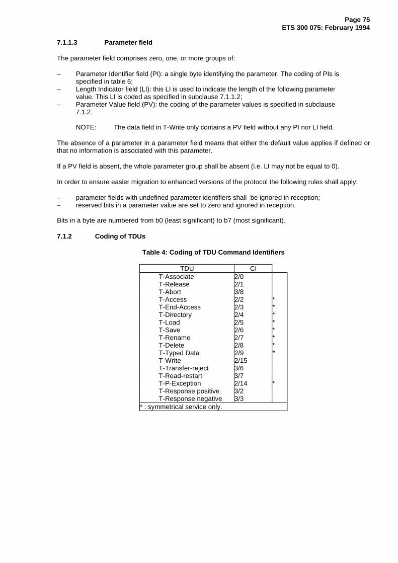
Page 75ETS 300 075: February 1994
7.1.1.3 Parameter field
The parameter field comprises zero, one, or more groups of:
– Parameter Identifier field (PI): a single byte identifying the parameter. The coding of PIs isspecified in table 6;
– Length Indicator field (LI): this LI is used to indicate the length of the following parametervalue. This LI is coded as specified in subclause 7.1.1.2;
– Parameter Value field (PV): the coding of the parameter values is specified in subclause7.1.2.
NOTE: The data field in T-Write only contains a PV field without any PI nor LI field.
The absence of a parameter in a parameter field means that either the default value applies if defined orthat no information is associated with this parameter.
If a PV field is absent, the whole parameter group shall be absent (i.e. LI may not be equal to 0).
In order to ensure easier migration to enhanced versions of the protocol the following rules shall apply:
– parameter fields with undefined parameter identifiers shall be ignored in reception;– reserved bits in a parameter value are set to zero and ignored in reception.
Bits in a byte are numbered from b0 (least significant) to b7 (most significant).
7.1.2 Coding of TDUs
Table 4: Coding of TDU Command Identifiers
TDU CIT-Associate 2/0T-Release 2/1T-Abort 3/8T-Access 2/2 *T-End-Access 2/3 *T-Directory 2/4 *T-Load 2/5 *T-Save 2/6 *T-Rename 2/7 *T-Delete 2/8 *T-Typed Data 2/9 *T-Write 2/15T-Transfer-reject 3/6T-Read-restart 3/7T-P-Exception 2/14 *T-Response positive 3/2T-Response negative 3/3
* : symmetrical service only.

Page 76ETS 300 075: February 1994
Table 5: Coding of TDU Parameter Identifiers
Parameter PIUser data 4/0Called address 4/1 *Calling address 4/2 *Result/Reason 4/3 *Role/function 4/4 *Application name 4/5Appl. resp. timeout 4/6Size/recovery/window 4/7 *Designation 4/8 *New name 4/9 *Request identification 4/10 *IdentificationExplicit confirmation
4/11 *
first/last, block number 4/12Transfer mode 4/13 *Recovery point 4/15 *Service class 5/1*: symmetrical service only.
7.1.2.1 Associate
7.1.2.1.1 Request
CI T-Associate = 2/0LI = L
* PI Called address = 4/1 LI = n < 255 PV = n bytes (see subclause 7.1.2.1.3)
* PI Calling address = 4/2 LI = n < 255 PV = n bytes (see subclause 7.1.2.1.4)
PI Application name = 4/5LI = n < 17PV = n bytes (see subclause 7.1.2.1.5)
PI App. resp timeout = 4/6LI = 0/1PV = 1 byte (see subclause 7.1.2.1.6)
PI Service class = 5/1LI = 0/1PV = 1 byte (see subclause 7.1.2.1.7)
PI Explicit Confirm. = 4/12LI = 0/1PV = 1 byte (see subclause 7.1.2.1.8)
* PI Identification = 4/11LI = n < 32PV = n bytes (see subclause 7.1.2.1.9)
* PI Request identif. = 4/10LI = 0/1PV = 1 byte (see subclause 7.1.2.1.10)
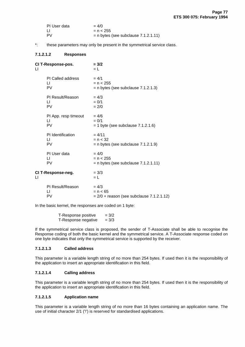
Page 77ETS 300 075: February 1994
PI User data = 4/0LI = n < 255PV = n bytes (see subclause 7.1.2.1.11)
*: these parameters may only be present in the symmetrical service class.
7.1.2.1.2 Responses
CI T-Response-pos. = 3/2LI = L
PI Called address = 4/1LI = n < 255PV = n bytes (see subclause 7.1.2.1.3)
PI Result/Reason = 4/3LI = 0/1PV = 2/0
PI App. resp timeout = 4/6LI = 0/1PV = 1 byte (see subclause 7.1.2.1.6)
PI Identification = 4/11LI = n < 32PV = n bytes (see subclause 7.1.2.1.9)
PI User data = 4/0LI = n < 255PV = n bytes (see subclause 7.1.2.1.11)
CI T-Response-neg. = 3/3LI = L
PI Result/Reason = 4/3LI = n < 65PV = 2/0 + reason (see subclause 7.1.2.1.12)
In the basic kernel, the responses are coded on 1 byte:
T-Response positive = 3/2T-Response negative = 3/3
If the symmetrical service class is proposed, the sender of T-Associate shall be able to recognise theResponse coding of both the basic kernel and the symmetrical service. A T-Associate response coded onone byte indicates that only the symmetrical service is supported by the receiver.
7.1.2.1.3 Called address
This parameter is a variable length string of no more than 254 bytes. If used then it is the responsibility ofthe application to insert an appropriate identification in this field.
7.1.2.1.4 Calling address
This parameter is a variable length string of no more than 254 bytes. If used then it is the responsibility ofthe application to insert an appropriate identification in this field.
7.1.2.1.5 Application name
This parameter is a variable length string of no more than 16 bytes containing an application name. Theuse of initial character 2/1 ('!') is reserved for standardised applications.
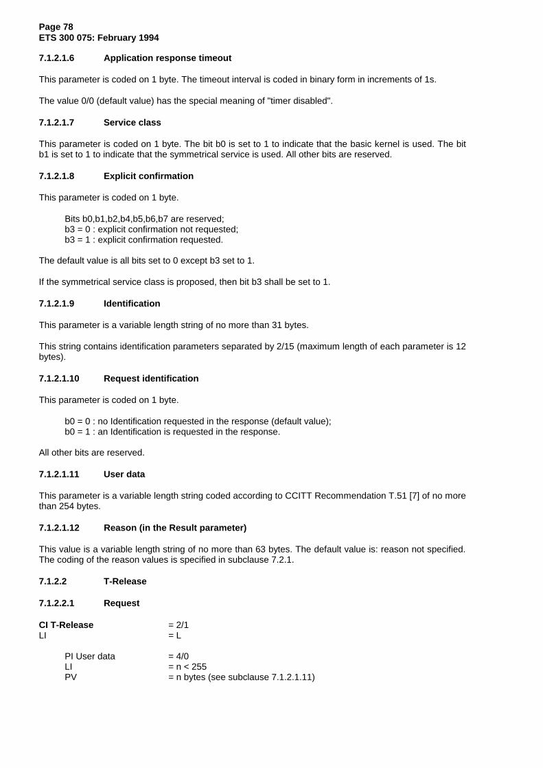
Page 78ETS 300 075: February 1994
7.1.2.1.6 Application response timeout
This parameter is coded on 1 byte. The timeout interval is coded in binary form in increments of 1s.
The value 0/0 (default value) has the special meaning of "timer disabled".
7.1.2.1.7 Service class
This parameter is coded on 1 byte. The bit b0 is set to 1 to indicate that the basic kernel is used. The bitb1 is set to 1 to indicate that the symmetrical service is used. All other bits are reserved.
7.1.2.1.8 Explicit confirmation
This parameter is coded on 1 byte.
Bits b0,b1,b2,b4,b5,b6,b7 are reserved;b3 = 0 : explicit confirmation not requested;b3 = 1 : explicit confirmation requested.
The default value is all bits set to 0 except b3 set to 1.
If the symmetrical service class is proposed, then bit b3 shall be set to 1.
7.1.2.1.9 Identification
This parameter is a variable length string of no more than 31 bytes.
This string contains identification parameters separated by 2/15 (maximum length of each parameter is 12bytes).
7.1.2.1.10 Request identification
This parameter is coded on 1 byte.
b0 = 0 : no Identification requested in the response (default value);b0 = 1 : an Identification is requested in the response.
All other bits are reserved.
7.1.2.1.11 User data
This parameter is a variable length string coded according to CCITT Recommendation T.51 [7] of no morethan 254 bytes.
7.1.2.1.12 Reason (in the Result parameter)
This value is a variable length string of no more than 63 bytes. The default value is: reason not specified.The coding of the reason values is specified in subclause 7.2.1.
7.1.2.2 T-Release
7.1.2.2.1 Request
CI T-Release = 2/1LI = L
PI User data = 4/0LI = n < 255PV = n bytes (see subclause 7.1.2.1.11)
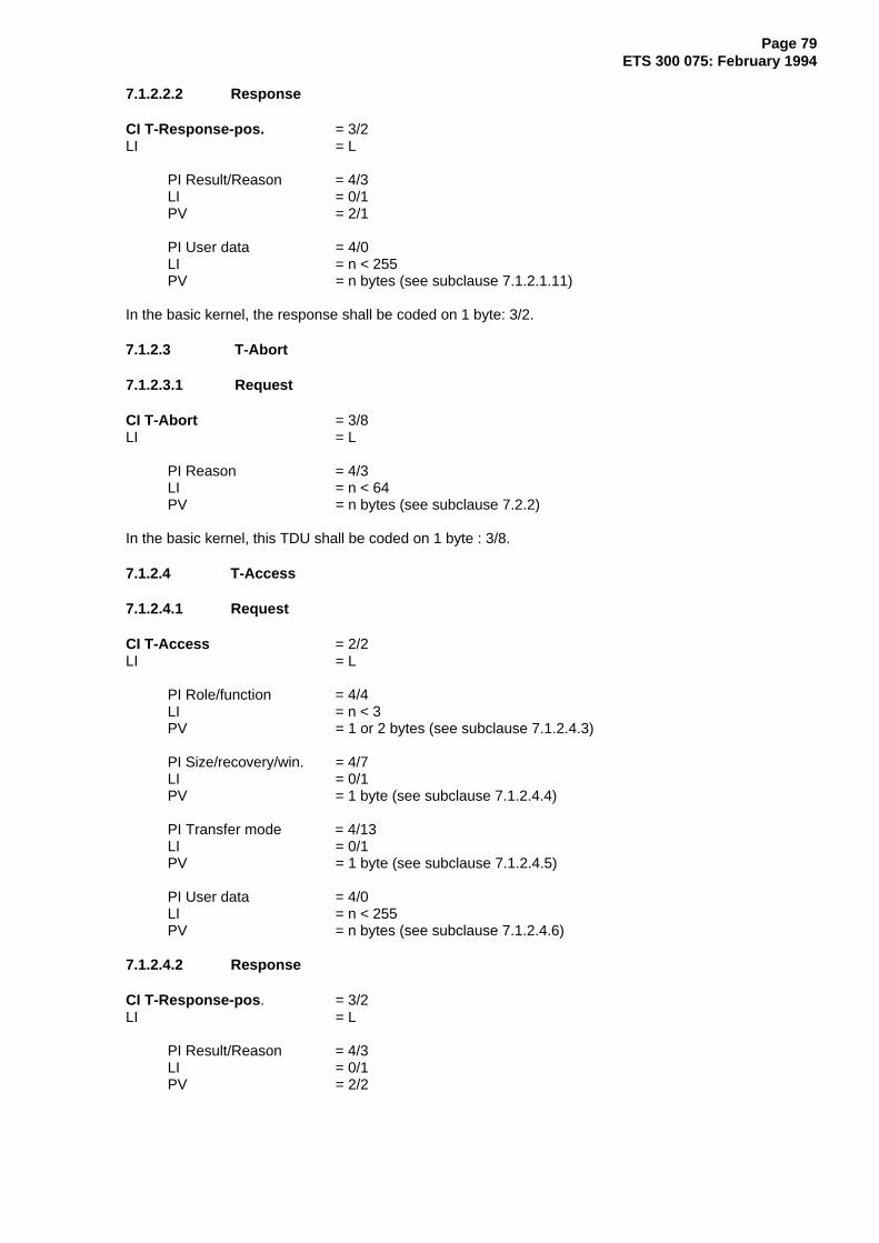
Page 79ETS 300 075: February 1994
7.1.2.2.2 Response
CI T-Response-pos. = 3/2LI = L
PI Result/Reason = 4/3LI = 0/1PV = 2/1
PI User data = 4/0LI = n < 255PV = n bytes (see subclause 7.1.2.1.11)
In the basic kernel, the response shall be coded on 1 byte: 3/2.
7.1.2.3 T-Abort
7.1.2.3.1 Request
CI T-Abort = 3/8LI = L
PI Reason = 4/3 LI = n < 64 PV = n bytes (see subclause 7.2.2)
In the basic kernel, this TDU shall be coded on 1 byte : 3/8.
7.1.2.4 T-Access
7.1.2.4.1 Request
CI T-Access = 2/2LI = L
PI Role/function = 4/4LI = n < 3PV = 1 or 2 bytes (see subclause 7.1.2.4.3)
PI Size/recovery/win. = 4/7LI = 0/1PV = 1 byte (see subclause 7.1.2.4.4)
PI Transfer mode = 4/13LI = 0/1PV = 1 byte (see subclause 7.1.2.4.5)
PI User data = 4/0LI = n < 255PV = n bytes (see subclause 7.1.2.4.6)
7.1.2.4.2 Response
CI T-Response-pos . = 3/2LI = L
PI Result/Reason = 4/3LI = 0/1PV = 2/2

Page 80ETS 300 075: February 1994
PI Role/function = 4/4LI = n < 3PV = 1 or 2 bytes (see subclause 7.1.2.4.3)PI Size/recovery/win. = 4/7LI = 0/1PV = 1 byte (see subclause 7.1.2.4.4)
PI Transfer mode = 4/13LI = 0/1PV = 1 byte (see subclause 7.1.2.4.5)
PI User data = 4/0LI = n < 255PV = n bytes (see subclause 7.1.2.4.6)
CI T-Response-neg . = 3/3LI = L
PI Result/Reason = 4/3LI = n < 65PV = 2/2 + reason (see subclause 7.1.2.1.12)
7.1.2.4.3 Role/function
This parameter is coded on 1 or 2 bytes.
The first byte is coded as follows:
b0 = 0 : Slave;b0 = 1 : Master.
If the role is Slave , the other bits indicate the TDUs which may be received by this entity:
b1 = 1 : T-Read-restart;b2 = 1 : T-Typed-data;b3 = 1 : T-Directory;b4 = 1 : T-Delete;b5 = 1 : T-Rename;b6 = 1 : T-Save;b7 = 1 : T-Load.
If the role is Master , the other bits indicate the TDUs which may be received by this entity:
b1 = 1 : T-Read-restart;b2 = 1 : T-Typed-data.
The other bits are reserved.
A second byte is reserved for future use and shall not be sent in this version of the protocol.
No default value.
7.1.2.4.4 Size, recovery, window
This parameter is coded on 1 byte. It indicates:
b0 = 0 : no recovery accepted by the Slave outside the mass transfer;b0 = 1 : recovery accepted by the Slave outside the mass transfer.
This bit has no meaning if the role is Master.
b3, b2, b1 indicate the maximum size of the application data, contained in a T-Write or T-Write (last),accepted by the Receiver:

Page 81ETS 300 075: February 1994
b3, b2, b1 = 000 : 512, 100 : 8 192,001 : 1 024, 101 : 16 384,010 : 2 048, 110 : 32 768,011 : 4 096, 111 : 65 528.
b4 : reserved.
b7, b6, b5 indicate the maximum number of consecutive T-Write or T-Write (last) (Confirmation required)the Receiver can accept before issuing an answer:
b7, b6, b5 = 000 : 1, 100 : 5,001 : 2, 101 : 6,010 : 3, 110 : 7,011 : 4, 111 : 8.
Default value: size: 1 024 bytes, no recovery, window: 1.
7.1.2.4.5 Transfer mode
This parameter is coded on 1 byte as follows:
b0 = 0: Basic Transfer Mode not supported by Slave (if bit b0 of Role/function is set to 0);Basic Transfer Mode not required by Master (if bit b0 of Role/function is set to 1).
b0 = 1: Basic Transfer Mode supported by Slave (if bit b0 of Role/function is set to 0);Basic Transfer Mode required by Master (if bit b0 of Role/function is set to 1).
b0 = 0: Default value.
All other bits are reserved.
7.1.2.4.6 User data
For Telesoftware and/or Printer Device applications see subclause 7.4.1.
7.1.2.5 T-End-access
7.1.2.5.1 Request
CI T-End-access = 2/3LI = L
PI Reason = 4/3LI = n < 64PV = n bytes (see subclause 7.2.2)
PI User data = 4/0LI = n < 255PV = n bytes (see subclause 7.1.2.1.11)
7.1.2.5.2 Response
CI T-Response-pos. = 3/2LI = L
PI Result/Reason = 4/3LI = 0/1PV = 2/3
PI User data = 4/0LI = n < 255PV = n bytes (see subclause 7.1.2.1.11)

Page 82ETS 300 075: February 1994
7.1.2.6 T-Directory
7.1.2.6.1 Request
CI T-Directory = 2/4LI = L
PI User data = 4/0LI = n < 255PV = n bytes (see subclause 7.1.2.6.3)
PI Designation = 4/8LI = n < 255PV = n bytes (see subclause 7.1.2.6.4)
7.1.2.6.2 Response
CI T-Response-pos . = 3/2LI = L
PI Result/Reason = 4/3LI = 0/1PV = 2/4
CI T-Response-neg . = 3/3LI = L
PI Result/Reason = 4/3LI = n < 65PV = 2/4 + reason (see subclause 7.1.2.1.12)
7.1.2.6.3 User data
For Telesoftware and/or Printer Device applications see subclause 7.4.2.
7.1.2.6.4 Designation
For Telesoftware and/or Printer Device applications see subclause 7.4.3.
7.1.2.7 T-Load
7.1.2.7.1 Request
CI T-Load = 2/5LI = L
PI User data = 4/0LI = n < 255PV = n bytes (see subclause 7.1.2.7.5)
PI Designation = 4/8LI = n < 255PV = n bytes (see subclause 7.1.2.7.4)
PI Recovery point = 4/15LI = n < 3PV = n bytes (see subclause 7.1.2.7.3)
7.1.2.7.2 Responses
CI T-Response-pos . = 3/2LI = L

Page 83ETS 300 075: February 1994
PI Result/Reason = 4/3LI = 0/1PV = 2/5
CI T-Response-neg . = 3/3LI = L
PI Result/Reason = 4/3LI = n < 65PV = 2/5 + reason (subclause 7.1.2.1.12)
7.1.2.7.3 Recovery point
This parameter shall only be present if this facility has been proposed and if the recovery is not performedfrom the beginning of the file.
The following byte(s) (maximum 2 bytes), if present, indicate(s) the block number.
The block number shall be coded in absolute binary form using all eight bits of each byte. It shall be codedon 1 byte between 0 and 255 and on 2 bytes between 256 and 65 535. If 2 bytes are used then the firstbyte contains the most significant bits.
The recovery points are numbered consecutively and the first block is coded 0.
7.1.2.7.4 Designation
For Telesoftware and/or Printer Device applications see subclause 7.4.4.
7.1.2.7.5 User data
For Telesoftware and/or Printer Device applications see subclause 7.4.5.
7.1.2.8 T-Save
7.1.2.8.1 Request
CI T-Save = 2/6LI = L
PI User data = 4/0LI = n < 255PV = n bytes (see subclause 7.1.2.7.5)
PI Designation = 4/8LI = n < 255PV = n bytes (see subclause 7.1.2.7.4)
PI Recovery point = 4/15LI = n < 3PV = n bytes (see subclause 7.1.2.7.3)
7.1.2.8.2 Responses
CI T-Response-pos . = 3/2LI = L
PI Result/Reason = 4/3LI = 0/1PV = 2/6

Page 84ETS 300 075: February 1994
CI T-Response-neg. = 3/3LI = L
PI Result/Reason = 4/3LI = n < 65PV = 2/6 + reason (see subclause 7.1.2.1.12)
7.1.2.9 T-Rename
7.1.2.9.1 Request
CI T-Rename = 2/7LI = L
PI User data = 4/0LI = n < 255PV = n bytes (see subclause 7.1.2.7.5)
PI Designation = 4/8LI = n < 255PV = n bytes (see subclause 7.1.2.9.3)
PI New name = 4/9LI = n < 255PV = n bytes (see subclause 7.1.2.9.3)
7.1.2.9.2 Responses
CI T-Response-pos . = 3/2LI = L
PI Result/Reason = 4/3LI = 0/1PV = 2/7
CI T-Response-neg . = 3/3LI = L
PI Result/Reason = 4/3LI = n < 65PV = 2/7 + reason (see subclause 7.1.2.1.12)
7.1.2.9.3 Designation, New name
The parameters Designation and New name contain the Transfer name and the New Transfer name ofthe file (see subclause 7.1.2.7.4 for coding).
7.1.2.10 T-Delete
7.1.2.10.1 Request
CI T-Delete = 2/8LI = L
PI User data = 4/0LI = n < 255PV = n bytes (see subclause 7.1.2.7.5)
PI Designation = 4/8LI = n < 255PV = n bytes (see subclause 7.1.2.7.4)

Page 85ETS 300 075: February 1994
7.1.2.10.2 Responses
CI T-Response-pos. = 3/2LI = L
PI Result/Reason = 4/3LI = 0/1PV = 2/8
CI T-Response-neg. = 3/3LI = L
PI Result/Reason = 4/3LI = n < 65PV = 2/8 + reason (see subclause 7.1.2.1.12)
7.1.2.11 T-Typed data
7.1.2.11.1 Request
CI T-Typed data = 2/9LI = L
PI User data = 4/0LI = n < 255PV = n bytes
7.1.2.12 T-Write
7.1.2.12.1 Request
CI T-Write = 2/15LI = L
PI Explicit confirm = 4/12LI = n < 4PV = n bytes (see subclause 7.1.2.12.4)
PV Data field = N bytes
The Data field length is implicitly given as: N = L - (n + 2) bytes.
In the symmetrical service N may be less or equal to the value negotiated in the T-Access service.
In the basic kernel N shall be less than 1 025 bytes.
7.1.2.12.2 Responses to a T-Write (not last)
CI T-Response-pos . = 3/2LI = L PI Result/Reason = 4/3 LI = n < 4 PV = 2/15 + block number (see subclause 7.1.2.12.5)
CI T-Response-neg . = 3/3LI = L
PI Result/Reason = 4/3 LI = n < 4 PV = 2/15 + block number (see subclause 7.1.2.12.5)

Page 86ETS 300 075: February 1994
In the basic kernel, the response shall be coded on one byte 3/2 or 3/3.
7.1.2.12.3 Responses to a T-Write (last)
CI T-Response-pos. = 3/2LI = L PI Result/Reason = 4/3 LI = n < 4 PV = 2/15 + block number (see subclause 7.1.2.12.5)
CI T-Response-neg. = 3/3LI = L
PI Result/Reason = 4/3 LI = n < 67 PV = 2/15+ block number + reason (see subclause 7.1.2.12.5)
Symmetrical service:
– a T-Response positive means file acceptation;– a T-Response negative means:
- if there is a user reason (erroneous file, other reason), file refusal;- if there is no reason, last block(s) refusal.
Basic kernel:
The response shall be coded on 1 byte 3/2 or 3/3.
– a T-Response positive means file acceptation.– a T-Response negative means file refusal.
7.1.2.12.4 Explicit confirmation, first/last, block number
This parameter shall be coded on 1 byte in the basic kernel, and on 1 or more bytes in the symmetricalservice.
The first byte contains the indication of explicit confirmation and the indication of first/last block.
Bits b7,b6,b5,b4,b2 are reserved.
b3 = 0 : explicit confirmation not requested.b3 = 1 : explicit confirmation requested.
b1,b0 = 0 0 : block0 1 : first block1 0 : last block1 1 : first and last block
When b1 = 1 (last block) b3 shall be set to 1.
The following byte(s) (maximum 2 bytes), if present, indicate(s) the block number.
The block number shall be coded in absolute binary form using all eight bits of each byte. It shall be codedon 1 byte between 0 and 255 and on 2 bytes between 256 and 65 535. If 2 bytes are used then the firstbyte contains the most significant bits.
The recovery points shall be numbered consecutively and the first block is coded 0.

Page 87ETS 300 075: February 1994
7.1.2.12.5 Result
This parameter contains the TDU code and the block number if present in the T-Write with the samecoding. It may also contain the reason of the negative response to the T-Write last.
7.1.2.13 T-Transfer-reject
7.1.2.13.1 Request
CI T-Transfer-reject = 3/6LI = L PI Reason = 4/3 LI = n < 64 PV = n bytes (see subclause 7.2.2)
In the basic kernel, this TDU shall be coded on 1 byte: 3/6.
7.1.2.14 T-Read-restart
7.1.2.14.1 Request
CI T-Read-restart = 3/7
7.1.2.15 T-P-Exception
7.1.2.15.1 Indication
CI T-P-Exception = 2/14LI = L
PI Reason = 4/3 LI = n < 64 PV = n bytes (see subclause 7.2.2)
7.2 Coding of provider and user refusals
The reason codes are contained in the Result parameter of some TDUs is to indicate either a user or aprovider refusal. The following codes are allocated. If the user reason is not specified then no code shallbe transmitted.
7.2.1 Reason codes in a T-Response negative
provider user
Called address incorrect 3/0 4/0 Calling address incorrect 3/1 4/1 Role refused 3/2 4/2 Insufficient primitives handled 4/3 Application name unknown 4/4 Service class refused 3/5 4/5 Erroneous recovery point 4/6 Erroneous designation 4/7 No answer to the request 4/8 Unknown file 4/9 Already existing file 4/10 Erroneous file (T-Write last) 4/11 Erroneous new name 4/12 New name already in use 4/13 Wrong identity 5/0 Erroneous user data 6/0 Erroneous user data, service unknown 6/0, 6/1

Page 88ETS 300 075: February 1994
Erroneous user data, group forbidden 6/0, 6/2 Other reason (+ optional string of char <63 bytes) 6/15 *
7.2.2 Reason in other TDUs
7.2.2.1 Provider reason
Repeated negative acknowledgements/ 7/0 repeated errors Delay expired 7/1 Unknown message 7/2 Syntax error/ missing parameter 7/3 Unrecoverable lower layer error 7/4 Protocol conflict 7/5 Primitive not handled 7/6 Other reason (+ optional string of char <63 bytes) 6/15 *
7.2.2.2 User reason
Wrong identification 5/0 Role refused 4/2 Insufficient primitives handled 4/3 Other reason (+ optional string of char <63 bytes) 6/15 *
*: the string shall contain displayable characters coded according to CCITT Recommendation T.51 [7].
7.3 File coding
The file coding scheme is a TLV encoding and uses the same principles as those described in subclause7.1.1 for TDUs parameter field encoding.
7.3.1 File structure coding
Each file has the following structure:
HEADER FILE CONTENT
The description file has the following structure:
HEADER of description file HEADER of File 1
HEADER of File n
The structure of headers is given in subclause 7.3.2.
7.3.2 File Header (FH) coding
The header is a sequence of attributes, each attribute is a group of PI, LI, PV.
The general structure of a header is the following:
PI FH LI PI LI PV PI LI PV I________________________________________________________I
The File Header PI (FH) is used to delimit the header of the file, its associated LI indicates the length ofthe list of attributes contained in the header. This parameter shall be always present, but if there is noheader then LI shall be set to 0/0.
The File Header PI shall be coded 3/0 .
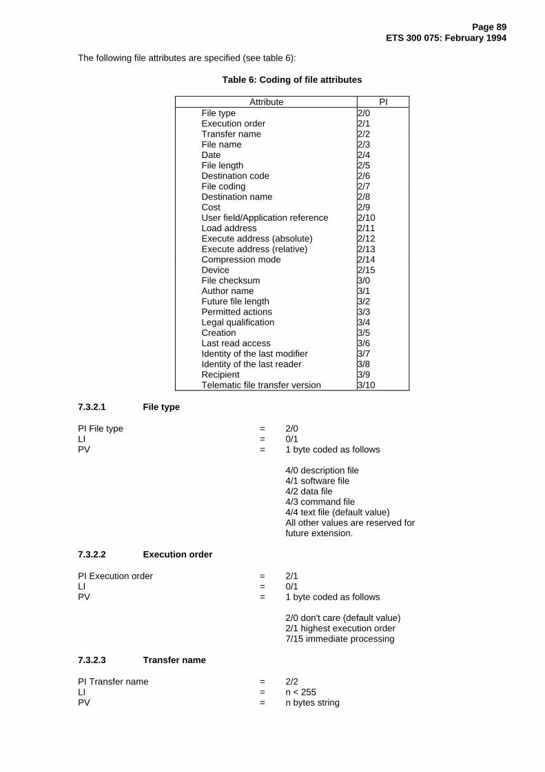
Page 89ETS 300 075: February 1994
The following file attributes are specified (see table 6):
Table 6: Coding of file attributes
Attribute PIFile type 2/0Execution order 2/1Transfer name 2/2File name 2/3Date 2/4File length 2/5Destination code 2/6File coding 2/7Destination name 2/8Cost 2/9User field/Application reference 2/10Load address 2/11Execute address (absolute) 2/12Execute address (relative) 2/13Compression mode 2/14Device 2/15File checksum 3/0Author name 3/1Future file length 3/2Permitted actions 3/3Legal qualification 3/4Creation 3/5Last read access 3/6Identity of the last modifier 3/7Identity of the last reader 3/8Recipient 3/9Telematic file transfer version 3/10
7.3.2.1 File type
PI File type = 2/0LI = 0/1PV = 1 byte coded as follows
4/0 description file 4/1 software file 4/2 data file 4/3 command file 4/4 text file (default value) All other values are reserved for future extension.
7.3.2.2 Execution order
PI Execution order = 2/1LI = 0/1PV = 1 byte coded as follows
2/0 don't care (default value) 2/1 highest execution order 7/15 immediate processing
7.3.2.3 Transfer name
PI Transfer name = 2/2LI = n < 255PV = n bytes string
Page 90ETS 300 075: February 1994
In the symmetrical service, the value is made up of keywords.
7.3.2.4 File name
PI File name = 2/3LI = n < 255PV = n bytes string
The value is a variable length string containing the file name.
7.3.2.5 Date
PI Date = 2/4LI = n < 13PV = n bytes string
The value is a variable length string of an even number of digits, coded in the range 3/0 to 3/9, specifyingthe date and time in the format yymmddhhmmss. The string may be truncated from the right to give alower degree of accuracy.
7.3.2.6 File length
PI File length = 2/5LI = n < 9PV = n bytes
The value is a variable length parameter in which the length of the uncompressed file is coded in anunsigned binary form. If the parameter is coded in more than one byte, then the first byte to be transmittedcontains the most significant bits.
NOTE: If a compression algorithm is used (see subclause 7.3.2.15) the value indicates thesize in bytes of the file content before performing the compression algorithm.
7.3.2.7 Destination code
PI Destination code = 2/6LI = 0/1PV = 1 byte coded as follows
4/0 do not care (default value) 4/1 foreground memory 4/2 background memory 4/3 cassette tape
All other values are reserved for future extension.
7.3.2.8 File coding
PI File coding = 2/7LI = n < 255PV = n bytes string
The first byte of the string is coded as follows:
software file: 2/0 text source 2/1 source in tokenised form 2/2 intermediate code 2/3 object code 2/4 execution code (default value)
Page 91ETS 300 075: February 1994
data file: 3/0 binary code (default value) 3/1 codes 2/0 to 7/14 of the videotex primary graphic set and the basic control codes specified in subclause 7.3.4.3.1
command file: 4/0 machine dependant (default value) 4/1 standard code
Text file: 5/0 other code5/1 As for 3/1 above (default value)
5/2 Videotex code profile 2 (as defined by ETS 300 072 [2]) 5/3 Videotex code profile 1 (as defined by ETS 300 072 [2]) 5/4 Videotex code profile 3 (as defined by ETS 300 072 [2]) 5/5 geometric 5/6 photographic 5/7 sound
All other values are reserved for future extension.
The default values indicated above depend on the value of the parameter file type and if file type is absentthe default value is 5/1.
Subsequent bytes, if present, identify by means of a text string a language (such as "BASIC","P-CODE"), or a target processor (such as "6502"). This may optionally be followed by a 2/15 ('/') and anidentification of the language dialect (such as "/MSDOS").
7.3.2.9 Destination name
PI Destination name = 2/8LI = n < 255PV = n bytes string
7.3.2.10 Cost
PI Cost = 2/9LI = n < 32PV = n bytes string
The string shall contain displayable characters coded according to CCITT Recommendation T.51 [7].
7.3.2.11 User field/Application reference
PI User field = 2/10LI = n < 255PV = n bytes string
The string shall contain displayable characters coded according to CCITT Recommendation T.51 [7].
7.3.2.12 Load address
PI Load address = 2/11LI = n < 9PV = n bytes
The value is a variable length parameter in which the load address is coded in absolute binary form usingall eight bits of each byte. If the parameter is coded in more than one byte, then the first byte to betransmitted contains the most significant bits.
Page 92ETS 300 075: February 1994
7.3.2.13 Execute address (absolute)
PI Execute address (absolute) = 2/12LI = n < 9PV = n bytes
The value is a variable length parameter in which the absolute execute address is coded in absolutebinary form using all eight bits of each byte. If the parameter is coded in more than one byte, then the firstbyte to be transmitted contains the most significant bits.
7.3.2.14 Execute address (relative)
PI Execute address (relative) = 2/13LI = n < 9PV = n bytes
The value is a variable length parameter in which the relative execute address is coded in absolute binaryform using all eight bits of each byte. If the parameter is coded in more than one byte, then the first byte tobe transmitted contains the most significant bits.
7.3.2.15 Compression mode
PI Compression mode = 2/14LI = 0/1PV = 1 byte coded as follows
4/0 basic compression mode 4/1 high efficiency compression mode
4/15 "application defined" compression mode
The use of compression algorithm applies to the file content.
The value 4/0 identifies the compression algorithm as defined below.
To repeat a byte the following characters should be transmitted:
X, RPT, N.
Where X is the byte to be repeated in the range 0/0 to 15/15,
RPT is the character 1/2, N is coded 2/0 + n, n being the number of repetitions in the range 0/1 to 5/15.
When this compression algorithm is in use the RPT code (1/2) should be transmitted twice.
The value 4/1 identifies a compression mode based on the "CCITT Recommendation V42.bis"compression mechanism.
NOTE: The same rules as the ones defined in the CCITT Recommendation apply for the useof this algorithm.
The value 4/15 identifies an "application defined" compression algorithm, as it is valid in Annex A. It issupposed that the receiver has the knowledge about the used compression algorithm.
All other values are reserved for future use. Absence of this parameter means that no compressionalgorithm is in use.
7.3.2.16 Device
PI Device = 2/15LI = n < 255PV = n bytes string

Page 93ETS 300 075: February 1994
The value is a variable length string comprising one or more fields. Fields are separated by the character4/0. The first field shall contain a name which is sufficient to distinguish the device type; the use of otherfields is not standardised. The use of the initial character 2/1 ('!') in each field is reserved for standardiseddevices.
If the first field commences with 2/1,5/0 ('!P'), then the required device is a printer. The coding of the datafield is specified in subclause 7.3.4.3.
A third byte may be present in the first field to indicate the minimum printer character repertoire required,as follows:
2/1: codes 2/0 - 2/2, 2/5 - 5/10 and 6/1 - 7/10 of the Videotex primary graphic set, and the control codesspecified in subclause 7.3.4.3.1;
codes 2/3, 2/4, 5/11-5/15, 7/11-7/15 may also be used but the representation of these characters isnot guaranteed in international communications and may be replaced by national applicationoriented variants.
2/2: the codes specified for 2/1, plus the mosaic characters in the first supplementary mosaic set.
2/3: the codes specified for 2/1, plus the SS2 control code, plus the following G2 characters: 2/3, 2/4,2/6, 2/12, 2/13, 2/14, 2/15, 3/0, 3/1, 4/1, 4/2, 4/3, 4/8, 4/11, 6/10, 7/10.The following characters shall be displayed: à é ù è â ê î ô û è ï oe ç Å‘ È É î Ô Ù OE Ç.
NOTE: All G2 characters may be selected, a given device /printer may display only a languageor application dependent subset.
2/4: the codes specified for 2/3, plus SI and SO control codes, plus the characters of the secondsupplementary mosaic set (G1) except the codes 4/0 to 5/14.
2/5: the alphanumeric repertoire specified in subclause 2.1.1 of ETS 300 072, Part 1 [2].
2/6: the alphanumeric and mosaic repertoires specified in subclauses 2.1.1 and 2.1.2 of ETS 300 072Part 1 [2].
2/7: the codes specified for 4/4, plus Dynamically Redefinable Character Set (DRCS) capability.
4/1: the codes specified for 2/1 plus the control codes specified in subclause 7.3.4.3.2.
4/2: the codes specified for 2/2 plus the control codes specified in subclause 7.3.4.3.2.
4/3: the codes specified for 2/3 plus the control codes specified in subclause 7.3.4.3.2.
4/4: the codes specified for 2/4 plus the control codes specified in subclause 7.3.4.3.2.
4/5: the codes specified for 2/5 plus the control codes specified in subclause 7.3.4.3.2.
4/6: the codes specified for 2/6 plus the control codes specified in subclause 7.3.4.3.2.
4/7: the codes specified for 2/7 plus the control codes specified in subclause 7.3.4.3.2.
4/15: private use.
All other values are reserved for future extension.
There may follow a string of arbitrary length comprising a sequence of codes of additional control and/orgraphic characters or characters sequences which are required to be reproduced (e.g., national currencysigns, accented characters, selected line drawing characters, graphic renditions).
If the repertoire specification byte is 4/15, the subsequent characters may be used to define the repertoire,and, possibly, also the page format or special stationery to be used.

Page 94ETS 300 075: February 1994
The second field, if present and of non-zero length, specifies the page format required. It may be either:
– a decimal number coded using the bytes 3/0 to 3/9, indicating that the printer shall be able to print rowsof at least this number of characters;
– a character, indicating that each record is to be formatted to a locally specified line length, line breaksbeing inserted in place of spaces, or following hyphens ('-', 2/13). Permitted characters are 4/12 ('L')indicating that the text is to be left justified, and 4/10 ('J') indicating that text preceding an inserted line-break should be justified to span the available line-length.
7.3.2.17 File checksum
PI File checksum = 3/0LI = 0/4PV = 4 bytes
The value is a 4-bytes length parameter containing a 32-bit frame check sequence.
The 32-bit FCS shall be the one's complement of the sum (modulo 2) of:
a) the remainder of:
xk (x31 + x30 + x29 + x28 + x27 + x26 + x25 + x24 + x23 + x22 + x21 + x20 + x19 + x18 + x17 +x16 + x15 + x14 + x13 + x12 + x11 + x10 + x9 + x8 + x7 + x6 + x5 + x4 + x3 + x2 + x1 + 1)divided (modulo 2) by the generator polynomialx32 + x26 + x23 + x22 + x16 + x12 + x11 + x10 + x8 + x7 + x5 + x4 + x2 + x + 1where k is the number of bits in the file content; and
b) the remainder of the division (modulo 2) by the generator polynomial:
x32 + x26 + x23 + x22 + x16 + x12 + x11 + x10 + x8 + x7 + x5 + x4 + x2 + x + 1of the product of x32 by the file content.
For the transmitter, the initial content of the register of the device computing the remainder of the divisionis preset to all ones and is then modified by division by the generator polynomial (as described above) ofthe file content; the one's complement of the resulting remainder is transmitted as the 32-bit FCS.
For the receiver, the initial content of the register of the device computing the remainder of the division ispreset to all ones.
The final remainder, after multiplication by x32 and then division (modulo 2) by the generator polynomialx32 + x26 + x23 + x22 + x16 + x12 + x11 + x10 + x8 + x7 + x5 + x4 + x2 + x + 1 of the serial incomingprotected bits and the FCS, shall be "1100 0111 0000 0100 1101 1101 0111 1011 (x31 through x0,respectively) in the absence of transmission errors.
7.3.2.18 Author name
PI Author name = 3/1LI = n < 255PV = n bytes string
The string shall contain displayable characters coded according to CCITT Recommendation T.51 [7].
7.3.2.19 Future file length
PI Future file length = 3/2LI = n < 9PV = n bytes
The value is a variable length parameter in which the expected length in bytes is coded in absolute binaryform using all eight bits of each byte. If the parameter is coded in more than one byte, then the first byte tobe transmitted contains the most significant bits.

Page 95ETS 300 075: February 1994
The nominal file length refers to the uncompressed file. Extension means an application dependent fileoperation and is different from the file decompression.
7.3.2.20 Permitted actions
PI Permitted actions = 3/3LI = n < 255PV = n bytes
If the first byte of the of the PV field as the value 4/0, the subsequent byte has the following meaning:
bit 0: read, bit 1: insert,bit 2: replace, bit 3: extend,bit 4: erase, bit 5: hide,bit 6: reserved, bit 7: not used.
If the first byte of the PV field is coded 4/7, the subsequent string shall contain displayable characterscoded according to CCITT Recommendation T.51 [7].
7.3.2.21 Legal qualification
PI Legal qualification = 3/4LI = n < 255PV = n bytes string
The string shall contain displayable characters coded according to CCITT Recommendation T.51 [7].
7.3.2.22 Creation
PI Creation = 3/5LI = n < 13PV = n bytes string
The value is a variable length string of an even number of digits, coded in the range 3/0 to 3/9, specifyingthe date and time in the format yymmddhhmmss. The string may be truncated from the right to give alower degree of accuracy.
7.3.2.23 Last read access
PI Last read access = 3/6LI = n < 13PV = n bytes string
The value is a variable length string of an even number of digits, coded in the range 3/0 to 3/9, specifyingthe date and time in the format yymmddhhmmss. The string may be truncated from the right to give alower degree of accuracy.
7.3.2.24 Identity of the last modifier
PI Identity of the last modifier = 3/7LI = n < 255PV = n bytes string
The string shall contain displayable characters coded according to CCITT Recommendation T.51 [7].
7.3.2.25 Identity of the last reader
PI Identity of the last reader = 3/8LI = n < 255PV = n bytes string

Page 96ETS 300 075: February 1994
The string shall contain displayable characters coded according to CCITT Recommendation T.51 [7].
7.3.2.26 Recipient
PI Recipient = 3/9LI = n < 255PV = n bytes string
The string shall contain displayable characters coded according to CCITT Recommendation T.51 [7].
7.3.2.27 Telematic file transfer version
PI Telematic file transfer version = 3/10LI = n < 255PV = n bytes string
The string shall contain displayable characters coded according to CCITT Recommendation T.51 [7].
7.3.3 Coding of the file content
7.3.3.1 Description file
The content of the description file is made of the file headers of all the other files part of the application toupload or to download.
Each file header is introduced by the parameter FH followed by the LI. The parameter value contains atleast the Transfer name and the Size of the file.
7.3.3.2 Other file
The other files contain their own data. This data follows the file header. They are not introduced by aparameter identifier.
7.3.4 Content of some specific files
7.3.4.1 Text file resulting of a T-DIRECTORY Request
This file contains a list of file Transfer names.
Each Transfer name is identified by one or more key words (maximum 8).
If there is more than one keyword they are separated by "/". A private field may follow the Transfer name,in this case it is introduced by the code 2/0 and it contains displayable characters (coded between 2/1 and7/14). The maximum length of the file name including separators is of no more than 70 bytes, and theprivate field length including introducer is of no more than 10 bytes.
Whatever the coding (character coding or Videotex coding) each field, including Transfer name andprivate field, is terminated by CR, LF (0/13, 0/10).
If the coding is Videotex, there are no sequence US x, y inside a field and no codes HT, VT, BS. The file ismade of pages of 24 rows and 40 characters. A given field does not overlap on two consecutive pages.
7.3.4.2 File of group B and C
These files are text files. They may be coded in character code or in Videotex code.
If the coding is Videotex, all the alphamosaic Videotex coding can be used. The file is made of pages of24 rows and 40 characters.

Page 97ETS 300 075: February 1994
7.3.4.3 Coding of data intended for a standardised printer
This subclause specifies the coding of data intended for the standardised printer (device !P) in the masstransfer phase.
In the auxiliary device application each transfer is intended to commence a new page or form, althoughthe transfer may extend to more than one page or form of text.
Graphic character codes shall be encoded according to the ETSI Videotex display syntax and to thedevice parameter of the file header.
Control codes shall be interpreted by the terminal as described in subclauses 7.3.4.3.1 and 7.3.4.3.2.
7.3.4.3.1 Basic control codes
7.3.4.3.1.1 NULL
Coded 0/0. This character shall be ignored.
7.3.4.3.1.2 Backspace. BS
Coded 0/8. The preferred action is to overprint character(s) previously received; the default action is toprint only the second character received.
7.3.4.3.1.3 Line feed. LF
Coded 0/10.
7.3.4.3.1.4 Clear screen. CS
Coded 0/12 and with the meaning "new page".
7.3.4.3.1.5 Carriage return. CR
Coded 0/13.
7.3.4.3.2 Extended control codes
The control codes specified for the virtual standardised printer are taken in general from the ETSIVideotex display syntax or from ISO 6429. Terminals are expected to recognise the following control codesyntax's:
ESC (2/x ...) 3/xESC (2/x ...) 4/xESC (2/x ...) 5/xESC (2/x ...) 6/xESC (2/x ...) 7/x
CSI (3/x ...) (2/x ...) 4/xCSI (3/x ...) (2/x ...) 5/xCSI (3/x ...) (2/x ...) 6/xCSI (3/x ...) (2/x ...) 7/x
Where (2/x ...) denotes zero, one or more occurrences of a code 2/x. ESC = 1/11, CSI = 1/11 5/11 or CSI= 9/11.
Any other single byte from columns 0, 1, 8, 9.
NOTE 1: The codes sequences ESC 4/x and ESC 5/x have the same meaning as the codes 8/xand 9/x respectively.

Page 98ETS 300 075: February 1994
NOTE 2: Control codes and code sequences are non-spacing except for spacing Videotexdisplay attributes (see subclause 7.3.4.3.2.8).
Terminals are expected to interpret and implement the following control codes:
7.3.4.3.2.1 Repeat. RPT
Coded 1/2, X and with the meaning "repeat the last graphic character a further n times", where n is thebinary value of the six least significants bits of X.
7.3.4.3.2.2 Active position address. APA
Coded 1/15, X', X, Y', Y (all parameters taken from columns 4 to 7 of the code table). This sequencecauses the active position to be moved to the row specified by the bytes X' and X, and the columnspecified by the bytes Y' and Y, provided that the specified row number is equal or higher than the currentrow number on the page. (The effect of attempting to overwrite text on the current row, or of addressing acolumn greater than that available on the printer, is not specified). The row and column are specified as12-bit values using the least significant 6 bits of 2 bytes, the first byte carrying the most significant bits. Ifboth row and column address 0 are specified, then the active position should remain in the row andcolumn in which it was situated before the APA sequence was received.
The operation of the following codes may be implementation dependant:
7.3.4.3.2.3 Unit separators. US
Coded 1/15, X, Y (X code taken from columns 2 and 3 of the code table). This code sequence identifiesthe start of non-alphamosaic-coded data which may be ignored by the terminal unless it is within thespecified repertoire of the terminal (e.g. DRCS definitions as required by the repertoire specification byte4/5). The end of the data string which may be ignored shall be marked by a US or APA sequence.
7.3.4.3.2.4 Partial line down. PLD
Coded 9/11, 4/11. The following characters within the same record, or until the next CS, US or PLUcharacter, are intended to be printed as subscripts; if PLU is already in effect then PLD has the effect onlyof cancelling the PLU.
7.3.4.3.2.5 Partial line up. PLU
Coded 9/11, 4/12. The following characters within the same record, or until CS, US or PLD character, areintended to be printed as superscripts; if PLD is already in effect then PLU has the effect only of cancellingthe PLD.
7.3.4.3.2.6 Select graphic rendition. SGR
Coded 9/11, (P1, (3/11, P2, (3/11, P3, (3/11, P4,)))) 6/13 where each parameter Pn, may take one of thevalues:
3/1 bold or increased intensity;3/3 italic;3/4 underlined;3/9 crossed-out.
Each parameter affects the representation of subsequent text up to the next SGR sequence, or to the endof the transfer if no further SGR is encountered.
7.3.4.3.2.7 Graphic size modification. GSM
Coded 9/11, P1, 3/11, P2, 2/0, 4/2 where the parameters P1 and P2 are each encoded as decimalnumbers using the bytes 3/0 to 3/9, specifying the required height and width respectively of subsequentcharacters as percentages of the default height and width. Each parameter affects the representation ofsubsequent text up to the next GSM sequence, or to the end of the transfer if no further GSM isencountered.

Page 99ETS 300 075: February 1994
7.3.4.3.2.8 Videotex display attributes
Coded 8/x or 9/x (or alternatively ESC 4/x or ESC 5/x). These attributes may be used to indicate apreferred foreground or background colour or character size for the printed text. (Use of a Videotexdisplay attribute to change character size is to be regarded as an alternative to the use of GSM, it does notalter the default height referenced by the GSM command. For example, the code 8/13 (double height) hasan identical effect in the terminal to the code sequence 9/11, 3/2, 3/0, 3/0, 3/11, 3/1, 3/0, 3/0, 2/0, 4/2.
7.4 Coding of parameters for the telesoftware and printer device applications
7.4.1 User data in T-Access and in T-(Access) Response positive
This parameter is used by the Slave to indicate in which groups the TDUs may be received:
Slave only:
Byte 1 b7 b6 b5 b4 b3 b2 b1 b0| | | | | | | | 0: refused| | | | | | | | 1: accepted
--------/ \-------------------------------------/ \--------------------------/SAVE DIRECTORY LOAD--------\ /-------------------------------------\ /--------------------------\
| | | | | | | || | | | | | | Group A| | | | | | Group B| | | | | Group C| | | | Group A, Application Name's subset| | | Group A| | Group B| Group CGroup A
Byte 2 b7 b6 b5 b4 b3 b2 b1 b0| | | | | | | || | | | | | | |
\--------------------------/ \------------------------/ \--------------/DELETE RENAME SAVE
/--------------------------\ /------------------------\ /--------------\| | | | | | | || | | | | | | Group B| | | | | | Group C| | | | | Group A| | | | Group B| | | Group C| | Group A| Group BGroup C
Default value : the primitives T-DIRECTORY, T-LOAD, T-SAVE, T-RENAME, T-DELETE, if they areauthorised, are only used in group A, which is equivalent to byte 1 equal to 8/9 and byte 2 equal to 2/4.
7.4.2 User data in T-Directory
This parameter is coded on up to 254 bytes, the first byte is coded as follows:
3/0 : group A , description file subset;3/1 : group A, default value;
3/2 : group B; 3/3 : group C.
Page 100ETS 300 075: February 1994
7.4.3 Designation in T-Directory
The Designation parameter is made up of one or more elementary words separated by the codes 2/11(displayed "+"), 2/15 (displayed "/"), 2/8 (displayed "(") and 2/9 (displayed ")").
In a byte sequence forming a correct sequence (see subclause 5.7 of the symmetrical serviceTelesoftware and printer device applications):
2/11 shall be interpreted as the logical operator OR; 2/15 shall be interpreted as the logical operator AND.
Parenthesis are used to indicate the scope of these logical operators.
The maximum number of elementary words is 8.
An elementary word is a byte sequence of no more than 12 bytes. Each byte can take any value between2/1 and 7/14 excepted 2/8, 2/9, 2/11 and 2/15, moreover this word cannot contain more than one byte2/10 (displayed "*").
7.4.4 Designation in T-Load and T-Save
The Designation parameter contains the Transfer name.
A Transfer name is made up of one or more key words. If a Transfer name is made up of several keywords, then they are separated by the code 2/15 (displayed "/").
The maximum number of key words in a Transfer name is (8). The maximum length of a Transfer name is70 bytes including all separators.
A key word is a byte sequence of no more than 12 bytes. Each byte can take any value between 2/1 and7/14 excepted 2/8, 2/9, 2/10, 2/11 and 2/15.
7.4.5 User data in T-Load, T-Save, T-Rename, T-Delete
This parameter is coded on up to 254 bytes, the first byte is coded as follows:
3/1 : group A, default value;3/2 : group B;3/3 : group C.
8 D-protocol specification
8.1 Modes
Translation modes: 4 translation modes are defined in order to provide for 8-bit transparency according tothe Videotex environment in which the protocol is to be used, these modes are specified in subclause 8.5.
Mode 1: No translation.Mode 2: 3-in-4 coding.Mode 3: Shift scheme 8-bits.Mode 4: Shift scheme 7-bits.
DDU modes: 7 DDU modes are defined in order to adapt the DDU delimitation codes to the Videotexenvironment in which the protocol is to be used. These modes are specified in subclause 8.5.
Mode A: 1 byte response encoding.Mode B: 1 byte plus terminator response encoding.Mode C: Symmetrical encoding with a one byte terminator.Mode D: Redefinable response encoding.Mode E: Redefinable response encoding with a End Delimiter.Mode F: Symmetrical encoding with a End Delimiter.Mode G: Symmetrical encoding.

Page 101ETS 300 075: February 1994
Other modes might be added to cover possible identified requirements related to the studies on thesymmetrical service.
8.2 General overview of the protocol
8.2.1 Structure of DDUs
The DDUs are used to delimit TDUs. DDUs are introduced by the Videotex processable data delimiter andare delimited by their internal syntax (see subclause 8.5). Optional 8-bit transparency capabilities(translation modes) and optional error detection facilities (BCS) are provided, but either or both of thesefeatures may be omitted if they are already provided by other means.
8.2.2 Flags
Flags are associated with D-Set-mode and D-Data DDUs. These flags are used by the error recoverymechanism. Only one of these flags may be set in a given DDU.
The more flag indicates, if set that this is not the last processable data VPDE in the Videotex frame,further processable data VPDEs should be expected without request.
The poll flag indicates, if set, that no further processable data VPDEs shall be sent until requested, andthat the receptor is expected to transmit a D-response-positive if this block and all previous blocks havebeen received correctly.
The confirmation flag indicates, if set that no further processable data VPDEs shall be sent untilrequested, and that the Slave is expected to return the TDU acknowledgement, after this block and allprevious blocks have been received correctly and processed by the application. This flag is set accordingto the semantic of the TDU which is conveyed by the corresponding D-Set mode or D-Data.
In symmetrical service:
- the no flag is used when ED is not used and if the D-Data DDU contains only a T-Abort, a T-Typeddata, a T-Transfer reject, a T-Read-restart, a T-P-Exception or a T-Response;
- the poll flag is used only if ED is used.
8.2.3 Error detection and recovery
This subclause gives an overview of the error detection and recovery mechanism.
The error detection is provided by using a sequence numbering or both a sequence numbering and achecksum. The use of error detection can be selected by sending a D-Set mode indicating the use ofeither sequence numbering (mode E and F only) or both sequence numbering and checksum (all modes).
The main principles of the error recovery mechanism are described below. The complete specification isgiven in subclause 8.4. This mechanism makes use of the sequence numbering and the BCS.
On receipt of an erroneous DDU (e.g. detected with an incorrect BCS or DDU out of sequence) thereceiver shall send a D-Response-negative.
If ED is in use, the TDUs contained in the D-Data DDUs shall be delivered to the upper layer when a pollor confirmation flag is contained in the last correctly received D-Data.
If ED is not in use the TDUs contained in the D-Data DDUs shall be delivered as soon as DDUs arereceived.
When a D-Response-negative is received the sender shall send again the DDUs following the last DDUwith a poll or confirmation flag set and for which a D-Response-positive or a T-response has beenreceived.
D-Response-negative is only used when ED is in use.
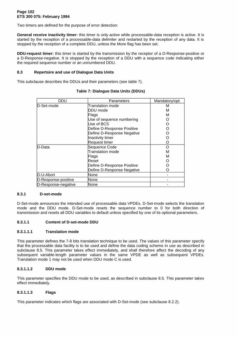
Page 102ETS 300 075: February 1994
Two timers are defined for the purpose of error detection:
General receive inactivity timer: this timer is only active while processable-data reception is active. It isstarted by the reception of a processable-data delimiter and restarted by the reception of any data. It isstopped by the reception of a complete DDU, unless the More flag has been set.
DDU-request timer: this timer is started by the transmission by the receptor of a D-Response-positive ora D-Response-negative. It is stopped by the reception of a DDU with a sequence code indicating eitherthe required sequence number or an unnumbered DDU.
8.3 Repertoire and use of Dialogue Data Units
This subclause describes the DDUs and their parameters (see table 7).
Table 7: Dialogue Data Units (DDUs)
DDU Parameters Mandatory/opt.D-Set-mode Translation mode M
DDU mode MFlags MUse of sequence numbering OUse of BCS ODefine D-Response Positive ODefine D-Response Negative OInactivity timer ORequest timer O
D-Data Sequence Code OTranslation mode MFlags MReset ODefine D-Response Positive ODefine D-Response Negative O
D-U-Abort None -D-Response-positive None -D-Response-negative None -
8.3.1 D-set-mode
D-Set-mode announces the intended use of processable data VPDEs. D-Set-mode selects the translationmode and the DDU mode. D-Set-mode resets the sequence number to 0 for both direction oftransmission and resets all DDU variables to default unless specified by one of its optional parameters.
8.3.1.1 Content of D-set-mode DDU
8.3.1.1.1 Translation mode
This parameter defines the 7-8 bits translation technique to be used. The values of this parameter specifythat the processable data facility is to be used and define the data coding scheme in use as described insubclause 8.5. This parameter takes effect immediately, and shall therefore affect the decoding of anysubsequent variable-length parameter values in the same VPDE as well as subsequent VPDEs.Translation mode 1 may not be used when DDU mode C is used.
8.3.1.1.2 DDU mode
This parameter specifies the DDU mode to be used, as described in subclause 8.5. This parameter takeseffect immediately.
8.3.1.1.3 Flags
This parameter indicates which flags are associated with D-Set-mode (see subclause 8.2.2).
Page 103ETS 300 075: February 1994
8.3.1.1.4 Use of ED
This parameter indicates that either sequence numbering or both BCS and sequence numbering shall beused.
8.3.1.1.5 Define D-Response-positive
This parameter may only be used when DDU mode D, E or F are selected, it specifies the coding of D-Response-positive. The redefinition has immediate effect. The default value is 3/0.
8.3.1.1.6 Define D-Response-negative
This parameter may only be used when DDU mode D, E or F are selected, it specifies the coding of D-Response-negative. The redefinition takes effect after the reception of a D-Response-positive. The defaultvalue is 3/1.
NOTE: To guard against possible deadlock in the event of double error, the sender shouldrecognise both the previous and new response negative until a response positive hasbeen received.
8.3.1.2 Sending D-set-mode
In the basic kernel, D-Set-mode may only be sent by the host. In the symmetrical service D-Set-mode maybe sent by both entities.
D-Set-mode shall not be preceded by any other processable data VPDE in a Videotex frame.
If the poll flag is set, the sender shall wait until a D-response-positive or a D-response negative isreceived.
If the confirmation flag is set the sender shall wait until the reception of a TDU.
8.3.1.3 Receiving D-set-mode
On reception of D-Set-mode, the processable data facility is activated and the translation mode and DDUmodes are selected according to the parameters of D-set-mode.
If the DDU is accepted and if the poll flag is set, a D-response-positive shall be returned.
If the confirmation flag is set the DDU layer waits for a local T-response or an incoming DDU.
If D-set mode or one of its parameters is rejected, a D-U-Abort shall be returned.
8.3.2 D-Data
This DDU is used to carry data for the upper layer (TDUs).
8.3.2.1 Content of D-Data DDU
8.3.2.1.1 Sequence code
This parameter contains a sequence number if the sequence numbering is in use (see subclause 8.4.2)otherwise this parameter is absent.
8.3.2.1.2 Translation mode
As specified in subclause 8.3.1.1.1.
8.3.2.1.3 Flags
This parameter indicates which flags are associated with D-Data (see subclause 8.2.2).

Page 104ETS 300 075: February 1994
8.3.2.1.4 Reset
This optional parameter enables selective reset of the sequence number to 0, and/or of the code(s) for D-Response-positive and D-Response-negative to default. Default is no reset. In case of conflict with theredefinition parameters (subclauses 8.3.2.1.5 and 8.3.2.1.6) the most recently received parameter takesprecedence. In the case of reset of a D-Response-negative, the reset takes effect after a D-Data with apoll or confirmation flag set has been accepted (see subclause 8.3.1.1.6).
8.3.2.1.5 D-Response-positive
As specified in subclause 8.3.1.1.5, but default is no change.
8.3.2.1.6 D-Response-negative
As specified in subclause 8.3.1.1.6, but default is no change.
8.3.2.2 Sending D-Data
In the basic kernel, D-Data may only be sent by the host. In the symmetrical service D-Data may be sentby both entities.
If the poll flag is set the sender shall wait until the reception of a D-response positive or negative.
If the confirmation flag is set the sender shall wait until the reception of a TDU.
8.3.2.3 Receiving D-Data
On reception of D-Data, the data shall be delivered to the upper layer if the poll or confirmation flag is set.If the more flag is set the data is buffered.
On reception of a valid D-Data, if the poll flag is set a D-response positive shall be sent, if the confirmationflag is set the DDU layer shall wait for a local T-response or an incoming DDU.
If ED is in use and the D-data is invalid (see subclause 8.4.6) a D-response negative shall be sent.
8.3.3 D-U-Abort
This DDU is used to abruptly terminate the use of processable data VPDE.
8.3.3.1 Content of D-U-Abort DDU
This DDU shall contain no parameter.
8.3.3.2 Sending D-U-Abort
Sending D-U-Abort causes the immediate termination of the DDU layer.
D-U-Abort may be sent at any time by the master after having sent a D-set-mode. No other processableVPDE shall be sent if a D-Set mode is sent.
D-U-Abort may be sent at any time by the slave after having received a D-set mode. All other processableVPDEs shall be discarded until a D-Set mode is received.
8.3.3.3 Receiving D-U-Abort
Receiving a D-U-Abort causes the immediate termination of the DDU layer. All other processable VPDEshall be discarded until a D-set mode is transmitted.
8.3.4 D-Response-positive
D-Response-positive is used to acknowledge a received DDU with the poll flag set.
Page 105ETS 300 075: February 1994
8.3.4.1 Content of D-Response-positive DDU
No parameter is associated with this DDU.
8.3.4.2 Sending D-Response-positive
A D-Response-positive shall be sent on the correct reception of a DDU with the poll flag set.
When sending a D-response-positive the DDU-request timer is started.
8.3.4.3 Receiving D-Response-positive
After reception of a D-response positive another DDU may be sent.
8.3.5 D-Response-negative
D-Response-negative is used to indicate an error in the process of receiving DDUs.
8.3.5.1 Content of D-Response-negative DDU
No parameter is associated with this DDU.
8.3.5.2 Sending D-Response-negative
A D-Response-negative may be sent on detection of a DDU error or timer expiration (see subclause 8.4).When sending a D-response-negative the DDU-request timer is started.
8.3.5.3 Receiving D-Response-negative
On reception of D-response negative, the transmission is resumed from the DDU following the lastacknowledged DDU (see subclause 8.4.6).
8.4 Error detection and recovery mechanism
8.4.1 Use of BCS
A checksum (BCS) is associated with each DDU (D-Set mode, D-Data) if the "Use of BCS" parameter isset in the initial D-Set mode DDU.
It is recommended not to use BCS when a data link layer is available.
The BCS is used to detect DDU transmission errors. The BCS encoding is specified in subclause 8.5.
8.4.2 Use of sequence numbering
Sequence numbering of the DDU (D-Set mode, D-Data) is used if the "Use of BCS" or the "Use ofSequence Numbering" is set in the D-Set mode DDU.
The sequence number is set to 0 when sending or receiving the D-Set-mode DDU. This sequencenumber is incremented by one with each D-Data.
The first D-Data after D-Set-mode has a sequence number of 1. The sequence number is reset to 0 byusing the "reset" parameter in D-Data.
An internal variable, Sn, contains the value of the next sequence number.
An other internal variable, Sa, contains the value of the sequence number associated with the lastacknowledged D-Data.
Sn and Sa shall be set to 0 when sending (resp. receiving) D-Set-mode or D-Data with the "reset"parameter.

Page 106ETS 300 075: February 1994
Sn shall be incremented by one after having sent a D-Data without the "reset" parameter. If ED is in use,the "sequence code" parameter contains the current value of Sn plus one. When Sn is equal to 31 theincrementation of Sn sets Sn to 0.
Sa shall be set to Sn when receiving (resp. sending) a D-Response-positive or a T-Response (which isconsidered as a positive response by the DDU layer).
NOTE 1: When Symmetrical DDU modes are used (C, F, G) the sequence numberingmechanism applies to both directions independently (i.e. a set of Sn and Sa isassociated with each direction of transmission).
D-Set-mode resets both sets of variables while the "reset" parameter of D-Data resetsonly the set of variables associated with the direction of transmission of D-Data.
A sequence number is detected as invalid when ED use has been selected and:
– no recovery has been initiated and the sequence code indicates a sequence number different fromSn+1; or
– recovery has been initiated and the sequence code indicates a sequence number greater than Snor lower than Sa+1,
NOTE 2: All these value comparisons are modulo 32.
8.4.3 Use of flags
If ED is in use, data (i.e. TDUs) shall be delivered to the upper layer upon reception of a valid DDU with apoll or confirmation flag set or upon reception of a valid D-U-Abort.
NOTE: Valid DDUs are DDUs which do not lead to detection of DDU exception or error (seesubclauses 8.4.6 and 8.4.7).
If BCS is not in use, data shall be delivered to the upper layer as soon as DDUs are received.
Due to limitations of sequence number encoding, the maximum number of subsequent D-Data without pollor confirmation flag shall not exceed 31.
8.4.4 Size of DDUs
A parameter of D-Set-mode indicates whether the maximum size of the data contained in D-Data shall notexceed 2 048 bytes or if there is no limit on this size.
If the basic kernel is used or if ED is in use this parameter shall indicate that this size is limited to 2 048bytes.
When ED is in use, for buffering reasons, the maximum size of data between two poll or confirmationflags shall not exceed 2 048 octets.
NOTE: All these sizes are the number of bytes which are transmitted on the line taking intoaccount the translation mode mechanism.
8.4.5 Use of timers
Two timers are defined for the purpose of DDU loss detection.
General receive inactivity timer: this timer is only active while processable-data reception is active. Itshall be started by the reception of a processable-data delimiter and restarted by the reception of anydata. It shall be stopped by the reception of a complete DDU, unless the More flag has been set.
DDU-request timer: it shall be started by the transmission of a D-Response positive or a D-Response-negative if ED is in use. It shall be stopped by the reception of a DDU with a sequence code indicating therequired sequence number if the ED is in use or by reception of a DDU without sequence code.
Page 107ETS 300 075: February 1994
8.4.6 Actions in the event of DDU errors
In the event of the following DDU reception errors, the entity which detects the error shall transmit a D-Response-negative to request retransmission:
– a DDU with an invalid sequence number (see subclause 8.4.2) (only when ED is in use);– a DDU in excess of permitted length (only when ED is in use);– a sequence of DDUs without poll or confirmation flags conveying more than 2 048 octets (only when
ED is in use);– a BCS error.
The entity which receives a D-Response-negative shall again send all the DDUs and their content fromthe last acknowledged DDU (DDU starting from Sa+1).
8.4.7 Actions in the event of DDU exceptions
The following exceptions shall not cause transmission of a D-response negative but are indicated to theupper layer and may cause higher level error recovery to be initiated:
– reception of D-set-mode DDU on an already established DDU connection;– unacceptable parameters or parameter values in a received D-Data DDU, (if ED is not in use, the
sequence code parameter value is not significant);– protocol error (syntactically incorrect DDU, or unrecognised DDU identifier, or unexpected DDU, or,
if ED is not in use, DDU in excess of permitted length);– excessive retransmission of D-Response-negative (more than 5 retransmissions);– unrecoverable error from the data link layer (if such indication is available);– expiration of general receive inactivity timer or DDU request timer when no sequence numbering is
in use;– a VPDE other than a processable data VPDE is received during the reception of a processable data
VPDE (that is a single 1/15 (US) character followed by a character other than 3/14). In this case thesubsequent VPDE should be processed.
8.4.8 Actions in the event of timer expiration
If the general receive inactivity timer or the DDU request timer expires and, if the sequence numbering isin use, their recovery may be attempted by issuing a D-response negative. The number of retransmissionof D-response negative is limited to 5 (see subclause 8.4.7).
8.5 Coding
8.5.1 Translation modes
The following transcoding schemes apply to all variable length DDU parameter and the whole of eachTDU.
8.5.1.1 Mode 1 (No translation)
Under this scheme no translation of data is performed, except that all US (1/15) characters in theprocessable data are represented by two contiguous US characters in the transmitted data stream.
8.5.1.2 Mode 2 (3-in-4 coding)
Each group of three bytes in the processable data is mapped into four bytes for transmission as shown intable 10. Any remaining group of one or two bytes at the end of a block of data is mapped into two or threebytes respectively, with undefined bits set to zero (a block consists of all bytes of a DDU to which thetranslation algorithm is applied (see subclause 8.5.3.1)).
8.5.1.3 Mode 3 (shift scheme - 8-bits)
In this scheme, bytes of processable data are each mapped into one or two bytes of transmitted data asshown in table 8. In mode 3 the most significant bit of each transmitted byte is taken into account. Note
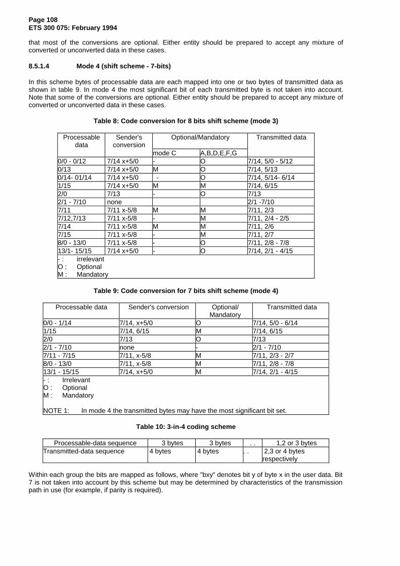
Page 108ETS 300 075: February 1994
that most of the conversions are optional. Either entity should be prepared to accept any mixture ofconverted or unconverted data in these cases.
8.5.1.4 Mode 4 (shift scheme - 7-bits)
In this scheme bytes of processable data are each mapped into one or two bytes of transmitted data asshown in table 9. In mode 4 the most significant bit of each transmitted byte is not taken into account.Note that some of the conversions are optional. Either entity should be prepared to accept any mixture ofconverted or unconverted data in these cases.
Table 8: Code conversion for 8 bits shift scheme (mode 3)
Processabledata
Sender'sconversion
Optional/Mandatory Transmitted data
mode C A,B,D,E,F,G0/0 - 0/12 7/14 x+5/0 - O 7/14, 5/0 - 5/120/13 7/14 x+5/0 M O 7/14, 5/130/14- 01/14 7/14 x+5/0 - O 7/14, 5/14- 6/141/15 7/14 x+5/0 M M 7/14, 6/152/0 7/13 - O 7/132/1 - 7/10 none 2/1 -7/107/11 7/11 x-5/8 M M 7/11, 2/37/12,7/13 7/11 x-5/8 - M 7/11, 2/4 - 2/57/14 7/11 x-5/8 M M 7/11, 2/67/15 7/11 x-5/8 - M 7/11, 2/78/0 - 13/0 7/11 x-5/8 - O 7/11, 2/8 - 7/813/1- 15/15 7/14 x+5/0 - O 7/14, 2/1 - 4/15- : irrelevantO : OptionalM : Mandatory
Table 9: Code conversion for 7 bits shift scheme (mode 4)
Processable data Sender's conversion Optional/ Transmitted data Mandatory
0/0 - 1/14 7/14, x+5/0 O 7/14, 5/0 - 6/141/15 7/14, 6/15 M 7/14, 6/152/0 7/13 O 7/132/1 - 7/10 none - 2/1 - 7/107/11 - 7/15 7/11, x-5/8 M 7/11, 2/3 - 2/78/0 - 13/0 7/11, x-5/8 M 7/11, 2/8 - 7/813/1 - 15/15 7/14, x+5/0 M 7/14, 2/1 - 4/15- : IrrelevantO : OptionalM : Mandatory
NOTE 1: In mode 4 the transmitted bytes may have the most significant bit set.
Table 10: 3-in-4 coding scheme
Processable-data sequence 3 bytes 3 bytes . . 1,2 or 3 bytesTransmitted-data sequence 4 bytes 4 bytes . . 2,3 or 4 bytes
respectively
Within each group the bits are mapped as follows, where "bxy" denotes bit y of byte x in the user data. Bit7 is not taken into account by this scheme but may be determined by characteristics of the transmissionpath in use (for example, if parity is required).
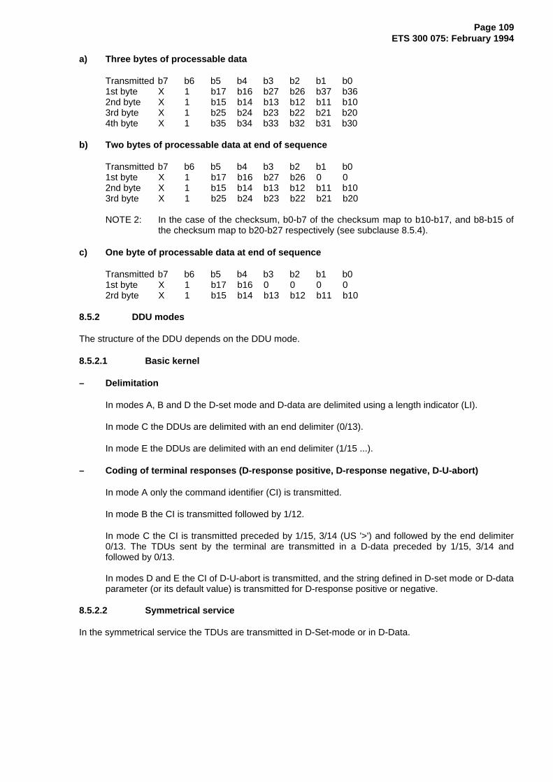
Page 109ETS 300 075: February 1994
a) Three bytes of processable data
Transmitted b7 b6 b5 b4 b3 b2 b1 b01st byte X 1 b17 b16 b27 b26 b37 b362nd byte X 1 b15 b14 b13 b12 b11 b103rd byte X 1 b25 b24 b23 b22 b21 b204th byte X 1 b35 b34 b33 b32 b31 b30
b) Two bytes of processable data at end of sequence
Transmitted b7 b6 b5 b4 b3 b2 b1 b0 1st byte X 1 b17 b16 b27 b26 0 0 2nd byte X 1 b15 b14 b13 b12 b11 b10 3rd byte X 1 b25 b24 b23 b22 b21 b20
NOTE 2: In the case of the checksum, b0-b7 of the checksum map to b10-b17, and b8-b15 ofthe checksum map to b20-b27 respectively (see subclause 8.5.4).
c) One byte of processable data at end of sequence
Transmitted b7 b6 b5 b4 b3 b2 b1 b0 1st byte X 1 b17 b16 0 0 0 0 2rd byte X 1 b15 b14 b13 b12 b11 b10
8.5.2 DDU modes
The structure of the DDU depends on the DDU mode.
8.5.2.1 Basic kernel
– Delimitation
In modes A, B and D the D-set mode and D-data are delimited using a length indicator (LI).
In mode C the DDUs are delimited with an end delimiter (0/13).
In mode E the DDUs are delimited with an end delimiter (1/15 ...).
– Coding of terminal responses (D-response positive, D-response negative, D-U-abort)
In mode A only the command identifier (CI) is transmitted.
In mode B the CI is transmitted followed by 1/12.
In mode C the CI is transmitted preceded by 1/15, 3/14 (US '>') and followed by the end delimiter0/13. The TDUs sent by the terminal are transmitted in a D-data preceded by 1/15, 3/14 andfollowed by 0/13.
In modes D and E the CI of D-U-abort is transmitted, and the string defined in D-set mode or D-dataparameter (or its default value) is transmitted for D-response positive or negative.
8.5.2.2 Symmetrical service
In the symmetrical service the TDUs are transmitted in D-Set-mode or in D-Data.

Page 110ETS 300 075: February 1994
8.5.3 Coding of DDUs
8.5.3.1 Structure of DDUs
The general structure of DDUs is the following:
SD CI Seq. code LI1 Param. field LI2 Data field TRAILER
I---------------------------I I---------------------------I
SD: Start Delimiter coded 1/15, 3/14 (US '>').
This start delimiter is present in all DDUs except in DDUs sent by the terminal in mode A, B, D, E.
CI: Command Identifier.
This field is a one byte field coded as described in subclause 8.5.3.2 (except in modes D, E and F for D-response positive or negative where it is replaced with a redefinable string).
Sequence code:
This field is present in D-set mode and D-data only if ED use is selected.The coding is given in subclause 8.5.3.2.2.1.
LI1: this field indicates the length of the parameter field.
It is coded as described in subclause 8.5.3.1.1.In D-Set mode this field is always present.In D-Data this field is only present in modes D and E.In other DDUs this field is absent.
Parameter field:
This field is coded as described in subclause 5.5.3.1.2.This field may only be present when LI1 is present and different from 0.
LI2: this field indicates the length of the data field, it is coded as described in subclause8.5.3.1.1.
This field is only present in D-set mode and D-data in modes A, B, D, E, F and G.
Data field:
This field may only be present in D-Set-mode and D-Data DDUs.
TRAILER:
In modes A, B, D and G:
This field is only present in D-Set-mode and D-Data if use of BCS has been selected.Its coding is given in subclause 8.5.4.
In mode C:
This field contains BCS in the same conditions that in the previous modes.The trailer is ended in all DDUs in mode C by an End Delimiter.It is coded 0/13 (Carriage Return).
In mode B:
This field is present in the terminal responses. It is coded 1/12 ('#') .
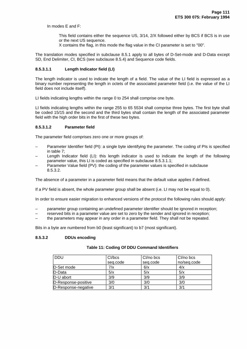
Page 111ETS 300 075: February 1994
In modes E and F:
This field contains either the sequence US, 3/14, 2/X followed either by BCS if BCS is in useor the next US sequence.X contains the flag, in this mode the flag value in the CI parameter is set to "00".
The translation modes specified in subclause 8.5.1 apply to all bytes of D-Set-mode and D-Data exceptSD, End Delimiter, CI, BCS (see subclause 8.5.4) and Sequence code fields.
8.5.3.1.1 Length Indicator field (LI)
The length indicator is used to indicate the length of a field. The value of the LI field is expressed as abinary number representing the length in octets of the associated parameter field (i.e. the value of the LIfield does not include itself).
LI fields indicating lengths within the range 0 to 254 shall comprise one byte.
LI fields indicating lengths within the range 255 to 65 5534 shall comprise three bytes. The first byte shallbe coded 15/15 and the second and the third bytes shall contain the length of the associated parameterfield with the high order bits in the first of these two bytes.
8.5.3.1.2 Parameter field
The parameter field comprises zero one or more groups of:
– Parameter Identifier field (PI): a single byte identifying the parameter. The coding of PIs is specifiedin table 7;
– Length Indicator field (LI): this length indicator is used to indicate the length of the followingparameter value, this LI is coded as specified in subclause 8.5.3.1.1;
– Parameter Value field (PV): the coding of the parameter values is specified in subclause8.5.3.2.
The absence of a parameter in a parameter field means that the default value applies if defined.
If a PV field is absent, the whole parameter group shall be absent (i.e. LI may not be equal to 0).
In order to ensure easier migration to enhanced versions of the protocol the following rules should apply:
– parameter group containing an undefined parameter identifier should be ignored in reception;– reserved bits in a parameter value are set to zero by the sender and ignored in reception;– the parameters may appear in any order in a parameter field. They shall not be repeated.
Bits in a byte are numbered from b0 (least significant) to b7 (most significant).
8.5.3.2 DDUs encoding
Table 11: Coding Of DDU Command Identifiers
DDU CI/bcs CI/no bcs CI/no bcs seq.code seq.code no/seq.code
D-Set mode 7/x 6/x 4/xD-Data 5/x 5/x 5/xD-U abort 3/9 3/9 3/9D-Response-positive 3/0 3/0 3/0D-Response-negative 3/1 3/1 3/1

Page 112ETS 300 075: February 1994
8.5.3.2.1 x values
bits b1, b0 = 0 0 : translation mode 4 = 0 1 : translation mode 2 = 1 0 : translation mode 3 = 1 1 : translation mode 1
bits b3, b2 = 0 0 : no flag set = 0 1 : confirmation flag set = 1 0 : more flag set = 1 1 : poll flag set
In modes E and F the flags are contained in the trailer. In this case in the CI parameter the bits b3, b2 areset to "00"; in the trailer bits b3, b2 of 2/x are set to "11" and the flags are coded in b1, b0 according totable 11.
8.5.3.2.2 Parameters encoding
Table 12: Coding Of DDU Parameter Identifiers
Parameter PISequence code 4/0-5/15,6/0Define D-response-positive 2/1Define D-response-negative 2/2DDU mode 2/3Inactivity timer 2/4Request timer 2/5Reset 2/6
NOTE: For translation mode, flags are part of the DDU code.
8.5.3.2.3 D-Set-mode
SD = 1/15 , 3/14
CI D-Set mode = 7/x or 6/x or 4/x
* Sequence code = 4/0 (see subclause 8.5.3.2.3.1) LI1 = 1 byte (see subclause 8.5.3.1.1)
PI DDU mode = 2/3 LI = 0/1 PV = 1 byte (see subclause 8.5.3.2.3.2)
* PI Define D-Resp-pos. = 2/1 LI = n < 17 PV = string (see subclause 8.5.3.2.3.3)
* PI Define D-Resp-neg = 2/2 LI = n < 17 PV = string (see subclause 8.5.3.2.3.4)
* PI Inactivity timer = 2/4 LI = 0/1 PV = 1 byte (see subclause 8.5.3.2.3.5)
* PI DDU request timer = 2/5 LI = 0/1 PV = 1 byte (see subclause 8.5.3.2.3.6)
* LI2 = 1 or 3 bytes (see subclause 8.5.3.1.1)

Page 113ETS 300 075: February 1994
* Data = n bytes
* Trailer
* BCS = 3 bytes (see subclause 8.5.4)
* End delimiter = 1 byte
or
* End delimiter = 1/15,3/14,2/x (see subclause 8.5.3.1)
* BCS = 3 bytes (see subclause 8.5.4)
*: the presence of the field is optional and subject to the conditions indicated in the referredsubclause.
8.5.3.2.3.1 This field is only present if error detection is provided
8.5.3.2.3.2 DDU mode parameter value
This parameter is coded on 1 byte. Bits b3, b5, b6, b7 are reserved.
bits b2, b1, b0 = 0 0 0 : mode A = 0 0 1 : mode B = 0 1 0 : mode C = 0 1 1 : mode D = 1 0 0 : mode E = 1 0 1 : mode F = 1 1 0 : mode G
bit b4 = 0 : D-Data size is limited to 2 048 bytes, = 1 : D-Data size is not limited.
8.5.3.2.3.3 Define D-response-positive parameter value
String of maximum length 16 bytes redefining the D-response-positive DDU. The default value is 3/0.
NOTE 1: It is the responsibility of the Master to ensure that the characters of the string cause noproblem in the bearer service.
This parameter is only present in modes D, E and F.
8.5.3.2.3.4 Define D-Response-negative parameter value
String of maximum length 16 bytes redefining the D-response-negative DDU. The default value is 3/1.
NOTE 2: It is the responsibility of the Master to ensure that the characters of the string cause noproblem in the bearer service.
This parameter is only present in modes D, E and F.
8.5.3.2.3.5 Inactivity timer parameter value
This parameter is coded on 1 byte. The timeout interval is coded in binary form in increments of 1 s. Thevalue 0/0 (default value) has the special significance of "timer disabled".
8.5.3.2.3.6 DDU Request timer parameter value
This parameter is coded on 1 byte. The timeout interval is coded in binary form in increments of 1s. Thevalue 0/0 (default value) has the special significance of "timer disabled".
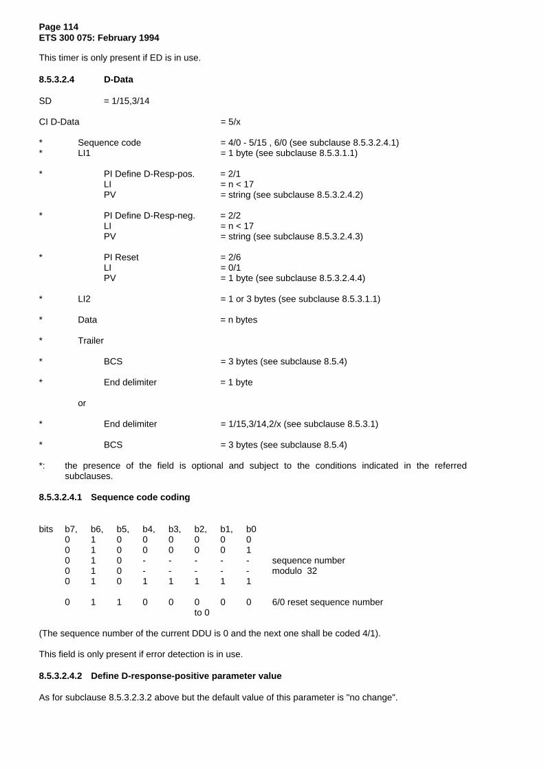
Page 114ETS 300 075: February 1994
This timer is only present if ED is in use.
8.5.3.2.4 D-Data
SD = 1/15,3/14
CI D-Data = 5/x
* Sequence code = 4/0 - 5/15 , 6/0 (see subclause 8.5.3.2.4.1)* LI1 = 1 byte (see subclause 8.5.3.1.1)
* PI Define D-Resp-pos. = 2/1 LI = n < 17 PV = string (see subclause 8.5.3.2.4.2)
* PI Define D-Resp-neg. = 2/2 LI = n < 17 PV = string (see subclause 8.5.3.2.4.3)
* PI Reset = 2/6LI = 0/1
PV = 1 byte (see subclause 8.5.3.2.4.4)
* LI2 = 1 or 3 bytes (see subclause 8.5.3.1.1)
* Data = n bytes
* Trailer
* BCS = 3 bytes (see subclause 8.5.4)
* End delimiter = 1 byte
or
* End delimiter = 1/15,3/14,2/x (see subclause 8.5.3.1)
* BCS = 3 bytes (see subclause 8.5.4)
*: the presence of the field is optional and subject to the conditions indicated in the referredsubclauses.
8.5.3.2.4.1 Sequence code coding
bits b7, b6, b5, b4, b3, b2, b1, b0 0 1 0 0 0 0 0 0 0 1 0 0 0 0 0 1 0 1 0 - - - - - sequence number 0 1 0 - - - - - modulo 32 0 1 0 1 1 1 1 1
0 1 1 0 0 0 0 0 6/0 reset sequence number to 0
(The sequence number of the current DDU is 0 and the next one shall be coded 4/1).
This field is only present if error detection is in use.
8.5.3.2.4.2 Define D-response-positive parameter value
As for subclause 8.5.3.2.3.2 above but the default value of this parameter is "no change".
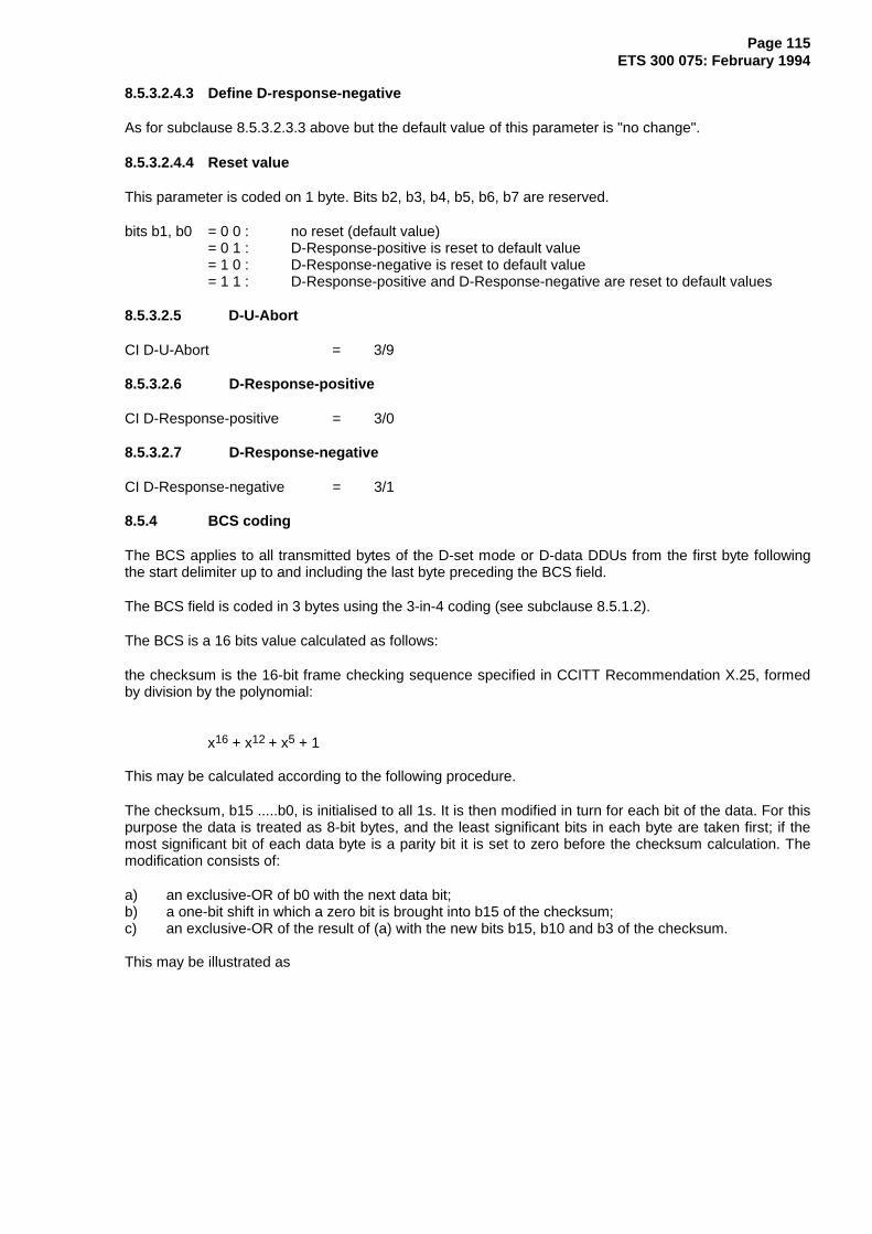
Page 115ETS 300 075: February 1994
8.5.3.2.4.3 Define D-response-negative
As for subclause 8.5.3.2.3.3 above but the default value of this parameter is "no change".
8.5.3.2.4.4 Reset value
This parameter is coded on 1 byte. Bits b2, b3, b4, b5, b6, b7 are reserved.
bits b1, b0 = 0 0 : no reset (default value) = 0 1 : D-Response-positive is reset to default value = 1 0 : D-Response-negative is reset to default value
= 1 1 : D-Response-positive and D-Response-negative are reset to default values
8.5.3.2.5 D-U-Abort
CI D-U-Abort = 3/9
8.5.3.2.6 D-Response-positive
CI D-Response-positive = 3/0
8.5.3.2.7 D-Response-negative
CI D-Response-negative = 3/1
8.5.4 BCS coding
The BCS applies to all transmitted bytes of the D-set mode or D-data DDUs from the first byte followingthe start delimiter up to and including the last byte preceding the BCS field.
The BCS field is coded in 3 bytes using the 3-in-4 coding (see subclause 8.5.1.2).
The BCS is a 16 bits value calculated as follows:
the checksum is the 16-bit frame checking sequence specified in CCITT Recommendation X.25, formedby division by the polynomial:
x16 + x12 + x5 + 1
This may be calculated according to the following procedure.
The checksum, b15 .....b0, is initialised to all 1s. It is then modified in turn for each bit of the data. For thispurpose the data is treated as 8-bit bytes, and the least significant bits in each byte are taken first; if themost significant bit of each data byte is a parity bit it is set to zero before the checksum calculation. Themodification consists of:
a) an exclusive-OR of b0 with the next data bit;b) a one-bit shift in which a zero bit is brought into b15 of the checksum;c) an exclusive-OR of the result of (a) with the new bits b15, b10 and b3 of the checksum.
This may be illustrated as

Page 116ETS 300 075: February 1994
Data↓
---------------------------------------------------XOR XOR XOR ↑ ↓ ↓ ↓ b15>b14>b13>b12>b11>b10>b9>b8>b7>b6>b5>b4>b3>b2>b1>b0
The checksum is finally complemented (1's complement) and mapped into three bytes as described insubclause 8.5.1.2 and illustrated in table 10.

Page 117ETS 300 075: February 1994
8.5.4.1 Example of CRC calculation
Figure 6 illustrates the calculation of the CRC checksum:
Next databit 15 14 13 12 11 10 9 8 7 6 5 4 3 2 1 0 bit byte
1 1 1 1 1 1 1 1 1 1 1 1 1 1 1 1 1 0 1 1 1 1 1 1 1 1 1 1 1 1 1 1 1 1 0 0 1 1 1 1 1 1 1 1 1 1 1 1 1 1 1 20 0 0 1 1 1 1 1 1 1 1 1 1 1 1 1 0 /1 0 0 0 1 0 1 1 1 1 1 1 0 1 1 1 0 71 1 0 0 0 0 0 1 1 1 1 1 0 0 1 1 10 1 1 0 0 0 0 0 1 1 1 1 1 0 0 1 01 0 1 1 0 1 0 0 0 1 1 1 0 1 0 0 0
0 1 0 1 1 0 1 0 0 0 1 1 1 0 1 0 00 0 1 0 1 1 0 1 0 0 0 1 1 1 0 1 01 0 0 1 0 0 1 0 1 0 0 0 0 1 1 0 0 40 1 0 0 1 0 0 1 0 1 0 0 0 0 1 1 0 /1 0 1 0 0 0 0 0 1 0 1 0 1 0 0 1 0 01 1 0 1 0 1 0 0 0 1 0 1 1 1 0 0 00 1 1 0 1 0 1 0 0 0 1 0 1 1 1 0 11 0 1 1 0 0 0 1 0 0 0 1 1 1 1 1 0
1 1 0 1 1 1 0 0 1 0 0 0 0 1 1 1 01 1 1 0 1 0 1 0 0 1 0 0 1 0 1 1 01 1 1 1 0 0 0 1 0 0 1 0 1 1 0 1 0 41 1 1 1 1 1 0 0 1 0 0 1 1 1 1 0 0 /0 1 1 1 1 1 1 0 0 1 0 0 1 1 1 1 0 01 0 1 1 1 0 1 1 0 0 1 0 1 1 1 1 01 1 0 1 1 0 0 1 1 0 0 1 1 1 1 1 10 1 1 0 1 1 0 0 1 1 0 0 1 1 1 1 0
1 0 1 1 0 0 1 0 0 1 1 0 1 1 1 1 10 1 0 1 1 0 0 1 0 0 1 1 0 1 1 1 10 0 1 0 1 1 0 0 1 0 0 1 1 0 1 1 1 10 0 0 1 0 1 1 0 0 1 0 0 1 1 0 1 1 /0 0 0 0 1 0 1 1 0 0 1 0 0 1 1 0 1 11 0 0 0 0 0 0 1 1 0 0 1 1 0 1 1 0 51 1 0 0 0 1 0 0 1 1 0 0 0 1 0 1 01 1 1 0 0 1 1 0 0 1 1 0 1 0 1 0 0
0 1 1 1 0 0 1 1 0 0 1 1 0 1 0 1 01 0 1 1 1 1 0 1 1 0 0 1 0 0 1 0 11 1 0 1 1 0 1 0 1 1 0 0 0 0 0 1 1 30 1 1 0 1 1 0 1 0 1 1 0 0 0 0 0 1 /1 0 1 1 0 0 1 0 1 0 1 1 1 0 0 0 1 11 1 0 1 1 1 0 1 0 1 0 1 0 1 0 0 1 41 1 1 0 1 0 1 0 1 0 1 0 0 0 1 0 00 1 1 1 0 1 0 1 0 1 0 1 0 0 0 1 0
1 0 1 1 1 1 1 0 1 0 1 0 0 0 0 0 00 1 0 1 1 1 1 1 0 1 0 1 0 0 0 0 00 0 1 0 1 1 1 1 1 0 1 0 1 0 0 0 0 30 0 0 1 0 1 1 1 1 1 0 1 0 1 0 0 0 /0 0 0 0 1 0 1 1 1 1 1 0 1 0 1 0 1 01 0 0 0 0 0 0 1 1 1 1 1 1 1 0 1 10 1 0 0 0 0 0 0 1 1 1 1 1 1 1 0 00 0 1 0 0 0 0 0 0 1 1 1 1 1 1 1 0
1 0 0 1 0 1 0 0 0 0 1 1 0 1 1 1 Final value0 1 1 0 1 0 1 1 1 1 0 0 1 0 0 0 Complement
Figure 6: Example of CRC calculation
These 16 bits map for transmission into:
1st byte: X 1 1 1 0 1 0 02nd byte: X 1 0 0 1 0 0 03rd byte: X 1 1 0 1 0 1 1

Page 118ETS 300 075: February 1994
Annex A (informative): A compression algorithm
/************************************************************ lzhuf.cwritten by Haruyasu Yoshizaki 11/20/1988some minor changes 4/6/1989comments translated by Haruhiko Okumura 4/7/1989
modified for Btx-FIF by InfoTeSys GmhH 1991-11-04: use malloc() instead of huge static areas: files have to be opened outside of this module: FCS-check inluded:: length field "long(Filesize)" has been removed from file
************************************************************/ #include stdio.h>#include <io.h>#include <stdlib.h>#include <string.h>#include <ctype.h>typedef unsigned char BYTE;#define ushort unsigned short#define EXIT_FAILURE 0#define EXIT_SUCCESS 1static int infile, outfile;static long codesize;static long InpSize, OutSize;static char wterr[] = "Can't write.";extern unsigned long FCS_32(BYTE CH, unsigned long crc_reg); static void near Error(char *message){
printf("\r\n%s\n", message);exit(EXIT_FAILURE);
}/********** LZSS compression **********/#define N 4096 /* buffer size */#define F 60 /* lookahead buffer size */#define THRESHOLD 2#define NIL N /* leaf of tree */#define text_buf_len (N + F - 1)static BYTE *text_buf;static int near match_position;static int near match_length;static short *lson; /* [N + 1]; */static short *rson; /* [N + 257]; */static short *dad; /* [N + 1]; */#define N_CHAR (256 - THRESHOLD + F)
/* kinds of characters (character code = 0..N_CHAR-1) */ #define T(N_CHAR * 2 - 1) /* size of table */
#define R (T - 1) /* position of root */#define MAX_FREQ 0x8000 /* updates tree when the */
/* root frequency comes to this value. */ struct lzh_env{
BYTE InpBuf[2048];short InpPos;short InpMax;BYTE OutBuf[1024];short OutPos;short OutMax;unsigned freq[T + 1]; /* frequency table */int prnt[T + N_CHAR];
/* pointers to parent nodes, except for the *//* elements [T..T + N_CHAR - 1] which are used to get */ /* the positions of leaves corresponding to thecodes. */
int son[T]; /* pointers to child nodes (son[], son[] + 1) */};static struct lzh_env *LZHENV;

Page 119ETS 300 075: February 1994
static int near InpByt(void){
if (LZHENV->InpPos >= LZHENV->InpMax){
LZHENV->InpMax = read(infile, LZHENV->InpBuf, LZHENV->InpMax);if (LZHENV->InpMax == 0) return(EOF);LZHENV->InpPos = 0;InpSize += LZHENV->InpMax;printf("\r %6ld\r", InpSize);
}return(LZHENV->InpBuf[LZHENV->InpPos++]);
} /* InpByt */static int near OutByt(short BY){
if (LZHENV->OutPos == LZHENV->OutMax){
write(outfile, LZHENV->OutBuf, LZHENV->OutPos); OutSize += LZHENV->OutPos; printf("\r\t\t\t\t\t%6ld\r", OutSize); LZHENV->OutPos = 0;
}LZHENV->OutBuf[LZHENV->OutPos++] = (BYTE) BY;
return(1);} /* OutByt */static void near InitTree(void) /* initialize trees */ {
register int i;for (i = N + 1; i <= N + 256; i++)
rson[i] = NIL; /* root */for (i = 0; i < N; i++)
dad[i] = NIL; /* node */} /* InitTree */static void near InsertNode(register int r) /* insert to tree */ {
register int p;int i, cmp;unsigned char *key;unsigned c;cmp = 1;key = &text_buf[r];p = N + 1 + key[0];rson[r] = lson[r] = NIL;match_length = 0;for ( ; ; ){
if (cmp >= 0){
if (rson[p] != NIL)p = rson[p];
else{
rson[p] = r;dad[r] = p;return;
}}else{
if (lson[p] != NIL)p = lson[p];
else{
lson[p] = r;dad[r] = p;return;
}}

Page 120ETS 300 075: February 1994
for (i = 1; i < F; i++)if ((cmp = key[i] - text_buf[p + i]) != 0) break;
if (i > THRESHOLD){
if (i > match_length){
match_position = ((r - p) & (N - 1)) - 1;if ((match_length = i) >= F)
break;}if (i == match_length){
if ((c = ((r - p) & (N - 1)) - 1) < match_position) {match_position = c;
}}
}}dad[r] = i = dad[p];lson[r] = lson[p];rson[r] = rson[p];dad[lson[p]] = r;dad[rson[p]] = r;if (rson[i] == p)
rson[i] = r;else
lson[i] = r;dad[p] = NIL; /* remove p */} /* InsertNode */static void near DeleteNode(register int p) /* remove from tree */ {
register int q;if (dad[p] == NIL)return; /* not registered */ if (rson[p] == NIL)
q = lson[p];else{
if (lson[p] == NIL)q = rson[p];
else{
q = lson[p];if (rson[q] != NIL){
do{
q = rson[q];} while (rson[q] != NIL);rson[dad[q]] = lson[q];dad[lson[q]] = dad[q];lson[q] = lson[p];dad[lson[p]] = q;
}rson[q] = rson[p];dad[rson[p]] = q;
}}dad[q] = dad[p];if (rson[dad[p]] == p)
rson[dad[p]] = q;else
lson[dad[p]] = q;dad[p] = NIL;
} /* DeleteNode */

Page 121ETS 300 075: February 1994
/* Huffman coding *//* table for encoding and decoding the upper 6 bits of position */ /* for encoding */static BYTE near p_len[64] ={
0x03, 0x04, 0x04, 0x04, 0x05, 0x05, 0x05, 0x05,0x05, 0x05, 0x05, 0x05, 0x06, 0x06, 0x06, 0x06, 0x06, 0x06, 0x06, 0x06, 0x06, 0x06, 0x06, 0x06, 0x07,0x07, 0x07, 0x07, 0x07, 0x07, 0x07, 0x07,0x07, 0x07, 0x07, 0x07, 0x07, 0x07, 0x07, 0x07, 0x07, 0x07, 0x07, 0x07, 0x07, 0x07, 0x07, 0x07, 0x08,0x08, 0x08, 0x08, 0x08, 0x08, 0x08, 0x08, 0x08, 0x08, 0x08, 0x08, 0x08, 0x08, 0x08, 0x08};static BYTE near p_code[64] ={0x00, 0x20, 0x30, 0x40, 0x50, 0x58, 0x60, 0x68, 0x70, 0x78, 0x80, 0x88, 0x90, 0x94, 0x98, 0x9C, 0xA0,0xA4, 0xA8, 0xAC, 0xB0, 0xB4, 0xB8, 0xBC, 0xC0, 0xC2, 0xC4, 0xC6, 0xC8, 0xCA, 0xCC, 0xCE, 0xD0,0xD2, 0xD4, 0xD6, 0xD8, 0xDA, 0xDC, 0xDE, 0xE0, 0xE2, 0xE4, 0xE6, 0xE8, 0xEA, 0xEC, 0xEE, 0xF0,0xF1, 0xF2, 0xF3, 0xF4, 0xF5, 0xF6, 0xF7, 0xF8, 0xF9, 0xFA, 0xFB, 0xFC, 0xFD, 0xFE, 0xFF};/* for decoding */static BYTE near d_code[256] ={0x00, 0x00, 0x00, 0x00, 0x00, 0x00, 0x00, 0x00, 0x00, 0x00, 0x00, 0x00, 0x00, 0x00, 0x00, 0x00, 0x00,0x00, 0x00, 0x00, 0x00, 0x00, 0x00, 0x00, 0x00, 0x00, 0x00, 0x00, 0x00, 0x00, 0x00, 0x00, 0x01, 0x01,0x01, 0x01, 0x01, 0x01, 0x01, 0x01, 0x01, 0x01, 0x01, 0x01, 0x01, 0x01, 0x01, 0x01, 0x02, 0x02, 0x02,0x02, 0x02, 0x02, 0x02, 0x02, 0x02, 0x02, 0x02, 0x02, 0x02, 0x02, 0x02, 0x02, 0x03, 0x03, 0x03, 0x03,0x03, 0x03, 0x03, 0x03, 0x03, 0x03, 0x03, 0x03, 0x03, 0x03, 0x03, 0x03, 0x04, 0x04, 0x04, 0x04, 0x04,0x04, 0x04, 0x04, 0x05, 0x05, 0x05, 0x05, 0x05, 0x05, 0x05, 0x05, 0x06, 0x06, 0x06, 0x06, 0x06, 0x06,0x06, 0x06, 0x07, 0x07, 0x07, 0x07, 0x07, 0x07, 0x07, 0x07, 0x08, 0x08, 0x08, 0x08, 0x08, 0x08, 0x08,0x08, 0x09, 0x09, 0x09, 0x09, 0x09, 0x09, 0x09, 0x09, 0x0A, 0x0A, 0x0A, 0x0A, 0x0A, 0x0A, 0x0A, 0x0A,0x0B, 0x0B, 0x0B, 0x0B, 0x0B, 0x0B, 0x0B, 0x0B, 0x0C, 0x0C, 0x0C, 0x0C, 0x0D, 0x0D, 0x0D, 0x0D,0x0E, 0x0E, 0x0E, 0x0E, 0x0F, 0x0F, 0x0F, 0x0F, 0x10, 0x10, 0x10, 0x10, 0x11, 0x11, 0x11, 0x11, 0x12,0x12, 0x12, 0x12, 0x13, 0x13, 0x13, 0x13, 0x14, 0x14, 0x14, 0x14, 0x15, 0x15, 0x15, 0x15, 0x16, 0x16,0x16, 0x16, 0x17, 0x17, 0x17, 0x17, 0x18, 0x18, 0x19, 0x19, 0x1A, 0x1A, 0x1B, 0x1B, 0x1C, 0x1C, 0x1D,0x1D, 0x1E, 0x1E, 0x1F, 0x1F, 0x20, 0x20, 0x21, 0x21, 0x22, 0x22, 0x23, 0x23, 0x24, 0x24, 0x25, 0x25,0x26, 0x26, 0x27, 0x27, 0x28, 0x28, 0x29, 0x29, 0x2A, 0x2A, 0x2B, 0x2B, 0x2C, 0x2C, 0x2D, 0x2D,0x2E, 0x2E, 0x2F, 0x2F, 0x30, 0x31, 0x32, 0x33, 0x34, 0x35, 0x36, 0x37, 0x38, 0x39, 0x3A, 0x3B, 0x3C,0x3D, 0x3E, 0x3F,};static BYTE near d_len[256] ={0x03, 0x03, 0x03, 0x03, 0x03, 0x03, 0x03, 0x03, 0x03, 0x03, 0x03, 0x03, 0x03, 0x03, 0x03, 0x03, 0x03,0x03, 0x03, 0x03, 0x03, 0x03, 0x03, 0x03, 0x03, 0x03, 0x03, 0x03, 0x03, 0x03, 0x03, 0x03, 0x04, 0x04,0x04, 0x04, 0x04, 0x04, 0x04, 0x04, 0x04, 0x04, 0x04, 0x04, 0x04, 0x04, 0x04, 0x04, 0x04, 0x04, 0x04,0x04, 0x04, 0x04, 0x04, 0x04, 0x04, 0x04, 0x04, 0x04, 0x04, 0x04, 0x04, 0x04, 0x04, 0x04, 0x04, 0x04,0x04, 0x04, 0x04, 0x04,0x04, 0x04, 0x04, 0x04, 0x04, 0x04, 0x04, 0x04, 0x05, 0x05, 0x05, 0x05, 0x05, 0x05, 0x05, 0x05, 0x05,0x05, 0x05, 0x05, 0x05, 0x05, 0x05, 0x05, 0x05, 0x05, 0x05, 0x05, 0x05, 0x05, 0x05, 0x05, 0x05, 0x05,0x05, 0x05, 0x05, 0x05, 0x05, 0x05, 0x05, 0x05, 0x05, 0x05, 0x05, 0x05, 0x05, 0x05, 0x05, 0x05, 0x05,0x05, 0x05, 0x05, 0x05, 0x05, 0x05, 0x05, 0x05, 0x05, 0x05, 0x05, 0x05, 0x05, 0x05, 0x05, 0x05, 0x05,0x05, 0x05, 0x05, 0x05, 0x06, 0x06, 0x06, 0x06, 0x06, 0x06, 0x06, 0x06, 0x06, 0x06, 0x06, 0x06, 0x06,0x06, 0x06, 0x06, 0x06, 0x06, 0x06, 0x06, 0x06, 0x06, 0x06, 0x06, 0x06, 0x06, 0x06, 0x06, 0x06, 0x06,0x06, 0x06, 0x06, 0x06, 0x06, 0x06, 0x06, 0x06, 0x06, 0x06, 0x06, 0x06, 0x06, 0x06, 0x06, 0x06, 0x06,0x06, 0x07, 0x07, 0x07, 0x07, 0x07, 0x07, 0x07, 0x07, 0x07, 0x07, 0x07, 0x07, 0x07, 0x07, 0x07, 0x07,0x07, 0x07, 0x07, 0x07, 0x07, 0x07, 0x07, 0x07, 0x07, 0x07, 0x07, 0x07, 0x07, 0x07, 0x07, 0x07, 0x07,0x07, 0x07, 0x07, 0x07, 0x07, 0x07, 0x07, 0x07, 0x07, 0x07, 0x07, 0x07, 0x07, 0x07, 0x07, 0x08, 0x08,0x08, 0x08, 0x08, 0x08, 0x08, 0x08, 0x08, 0x08, 0x08, 0x08, 0x08, 0x08, 0x08, 0x08,};static unsigned near getbuf = 0;static int near getlen = 0;static int near GetBit(void) /* get one bit */ {
register int i, j;j = getlen;while (j <= 8){
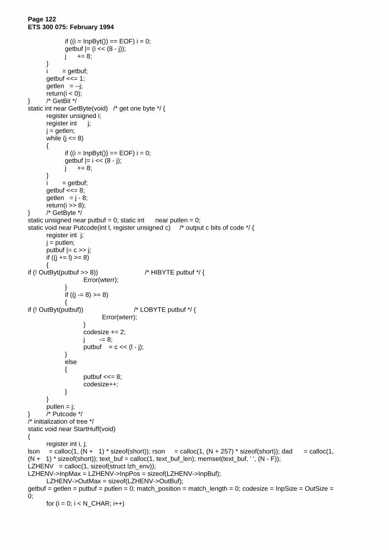
Page 122ETS 300 075: February 1994
if ((i = InpByt()) == EOF) i = 0;getbuf |= (i << (8 - j));j += 8;
}i = getbuf;getbuf <<= 1;getlen = --j;return(i < 0);
} /* GetBit */static int near GetByte(void) /* get one byte */ {
register unsigned i;register int j;j = getlen;while (j <= 8){
if ((i = InpByt()) == EOF) i = 0;getbuf |= i << (8 - j);j += 8;
}i = getbuf;getbuf <<= 8;getlen = j - 8;return(i >> 8);
} /* GetByte */static unsigned near putbuf = 0; static int near putlen = 0;static void near Putcode(int l, register unsigned c) /* output c bits of code */ {
register int j;j = putlen;putbuf |= c >> j;if ((j += l) >= 8){
if (! OutByt(putbuf >> 8)) /* HIBYTE putbuf */ {Error(wterr);
}if ((j -= 8) >= 8){
if (! OutByt(putbuf)) /* LOBYTE putbuf */ {Error(wterr);
}codesize += 2;j -= 8;putbuf = c << (l - j);
}else{
putbuf <<= 8;codesize++;
}}putlen = j;
} /* Putcode *//* initialization of tree */static void near StartHuff(void){
register int i, j;lson = calloc(1, (N + 1) * sizeof(short)); rson = calloc(1, (N + 257) * sizeof(short)); dad = calloc(1,(N + 1) * sizeof(short)); text_buf = calloc(1, text_buf_len); memset(text_buf, ' ', (N - F));LZHENV = calloc(1, sizeof(struct lzh_env));LZHENV->InpMax = LZHENV->InpPos = sizeof(LZHENV->InpBuf);
LZHENV->OutMax = sizeof(LZHENV->OutBuf);getbuf = getlen = putbuf = putlen = 0; match_position = match_length = 0; codesize = InpSize = OutSize =0;
for (i = 0; i < N_CHAR; i++)
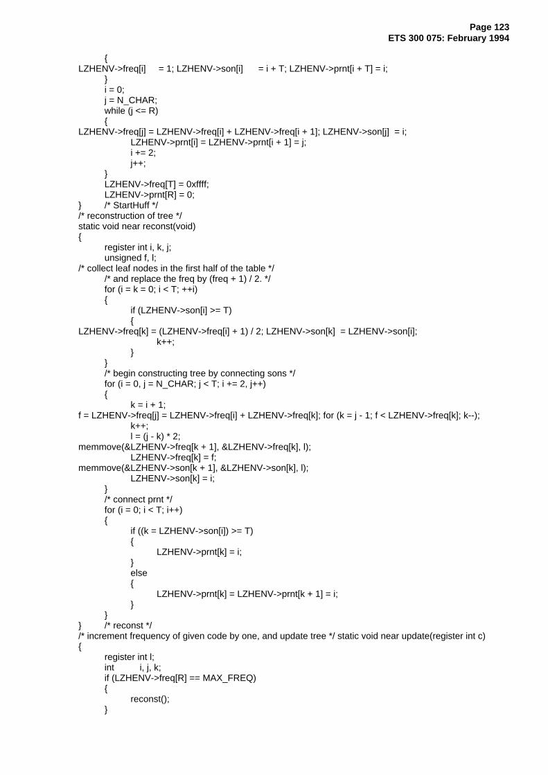
Page 123ETS 300 075: February 1994
{LZHENV->freq[i] = 1; LZHENV->son[i] = i + T; LZHENV->prnt[i + T] = i;
}i = 0;j = N_CHAR;while (j <= R){
LZHENV->freq[j] = LZHENV->freq[i] + LZHENV->freq[i + 1]; LZHENV->son[j] = i;LZHENV->prnt[i] = LZHENV->prnt[i + 1] = j;i += 2;j++;
}LZHENV->freq[T] = 0xffff;LZHENV->prnt[R] = 0;
} /* StartHuff *//* reconstruction of tree */static void near reconst(void){
register int i, k, j;unsigned f, l;
/* collect leaf nodes in the first half of the table *//* and replace the freq by (freq + 1) / 2. */for (i = k = 0; i < T; ++i){
if (LZHENV->son[i] >= T){
LZHENV->freq[k] = (LZHENV->freq[i] + 1) / 2; LZHENV->son[k] = LZHENV->son[i];k++;
}}/* begin constructing tree by connecting sons */for (i = 0, j = N_CHAR; j < T; i += 2, j++){
k = i + 1;f = LZHENV->freq[j] = LZHENV->freq[i] + LZHENV->freq[k]; for (k = j - 1; f < LZHENV->freq[k]; k--);
k++;l = (j - k) * 2;
memmove(&LZHENV->freq[k + 1], &LZHENV->freq[k], l);LZHENV->freq[k] = f;
memmove(&LZHENV->son[k + 1], &LZHENV->son[k], l);LZHENV->son[k] = i;
}/* connect prnt */for (i = 0; i < T; i++){
if ((k = LZHENV->son[i]) >= T){
LZHENV->prnt[k] = i;}else{
LZHENV->prnt[k] = LZHENV->prnt[k + 1] = i;}
}} /* reconst *//* increment frequency of given code by one, and update tree */ static void near update(register int c){
register int l;int i, j, k;if (LZHENV->freq[R] == MAX_FREQ){
reconst();}

Page 124ETS 300 075: February 1994
c = LZHENV->prnt[c + T];do{
k = ++LZHENV->freq[c];/* if the order is disturbed, exchange nodes */if (k > LZHENV->freq[l = c + 1]){
while (k > LZHENV->freq[++l]);l--;LZHENV->freq[c] = LZHENV->freq[l];LZHENV->freq[l] = k;i = LZHENV->son[c];LZHENV->prnt[i] = l;if (i < T) LZHENV->prnt[i + 1] = l;
j = LZHENV->son[l]; LZHENV->son[l] = i;LZHENV->prnt[j] = c;if (j < T) LZHENV->prnt[j + 1] = c;LZHENV->son[c] = j;c = l;
}} while ((c = LZHENV->prnt[c]) != 0); /* repeat up to root */} /* update *///static unsigned code, len;static void near EncodeChar(unsigned c){
register unsigned i;register int k, j;i = j = 0;k = LZHENV->prnt[c + T];
/* travel from leaf to root */do{
i >>= 1;/* if node's address is odd-numbered, choose bigger brother node */ if (k & 1) i += 0x8000;
j++;} while ((k = LZHENV->prnt[k]) != R);Putcode(j, i);
// code = i;// len = j;
update(c);} /* EncodeChar */static void near EncodePosition(register unsigned c){
register unsigned i;/* output upper 6 bits by table lookup */i = c >> 6;Putcode(p_len[i], (unsigned) p_code[i] << 8);/* output lower 6 bits verbatim */Putcode(6, (c & 0x3f) << 10);
} /* EncodePosition */static void near EncodeEnd(void){
if (putlen){
if (! OutByt(putbuf >> 8)) /* HIBYTE putbuf */ {Error(wterr);
}codesize++;
}} /* EncodeEnd */static int near DecodeChar(void){

Page 125ETS 300 075: February 1994
register unsigned c;c = LZHENV->son[R];/* travel from root to leaf, */
/* choosing the smaller child node (son[]) if the read bit is 0, *//* the bigger (son[]+1} if 1 */while (c < T){
c += GetBit();c = LZHENV->son[c];
}c -= T;update(c);return(c);
} /* DecodeChar */static int near DecodePosition(void){
register unsigned i, j, c;/* recover upper 6 bits from table */
i = GetByte();c = ((unsigned) d_code[i] << 6);
j = d_len[i];/* read lower 6 bits verbatim */
j -= 2;while (j--){
i = (i << 1) + GetBit();}return(c | (i & 0x3f));
} /* DecodePosition *//* compression */void LZH_Encode(int fi, int fo, unsigned long *CRC_32) /* compression */ {
register int r, s;int i, c, len, last_match_length;long textsize;unsigned long INPCRC = 0xffffffff;infile = fi;outfile = fo;textsize = filelength(infile);StartHuff();InitTree();r = N - F;
for (s = 0; s < F && (c = InpByt()) != EOF; ++s){
INPCRC = FCS_32((BYTE) c, INPCRC); text_buf[r + s] = (BYTE) c;}len = s;
for (s = 1; s <= F; ++s) InsertNode(r - s);InsertNode(r);s = 0;do{
if (match_length > len)match_length = len;
if (match_length <= THRESHOLD){
match_length = 1;EncodeChar(text_buf[r]);
}else{
EncodeChar(255 - THRESHOLD + match_length); EncodePosition(match_position);}last_match_length = match_length;

Page 126ETS 300 075: February 1994
for (i = 0; i < last_match_length && (c = InpByt()) != EOF; ++i) {INPCRC = FCS_32((BYTE) c, INPCRC);DeleteNode(s);text_buf[s] = (BYTE) c;if (s < F - 1) text_buf[s + N] = (BYTE) c;s = (s + 1) & (N - 1);r = (r + 1) & (N - 1);InsertNode(r);
}while (i++ < last_match_length){
DeleteNode(s);s = (s + 1) & (N - 1);r = (r + 1) & (N - 1);if (--len) InsertNode(r);
}} while (len > 0);EncodeEnd();if (LZHENV->OutPos){
write(outfile, LZHENV->OutBuf, LZHENV->OutPos); OutSize += LZHENV->OutPos;}
printf("In : %6ld bytes\n", InpSize); printf("Out: %6ld bytes\n", OutSize);// printf("Out/In: %.3f\n", (double) InpSize / OutSize);
free(LZHENV);free(text_buf);free(dad);free(lson);free(rson);*CRC_32 = INPCRC;
} /* Encode *//* recover */ void LZH_Decode(int fi, int fo,
long filesize, unsigned long *CRC_32){
register int i, j, k, r, c;unsigned long count;unsigned long OUTCRC = 0xffffffff;infile = fi;outfile = fo;StartHuff();r = N - F;for (count = 0; count < filesize; ){
if ((c = DecodeChar()) < 256){
if (! OutByt(c)){
Error(wterr);}
OUTCRC = FCS_32((BYTE) c, OUTCRC); text_buf[r++] = (BYTE) c;r &= (N - 1);count++;
}else{
i = (r - DecodePosition() - 1) & (N - 1); j = c - 255 + THRESHOLD;for (k = 0; k < j; ++k){
c = text_buf[(i + k) & (N - 1)]; if (! OutByt(c)){
Error(wterr);}
OUTCRC = FCS_32((BYTE) c, OUTCRC); text_buf[r++] = (BYTE) c;

Page 127ETS 300 075: February 1994
r &= (N - 1);count++;
}}
}if (LZHENV->OutPos) write(outfile, LZHENV->OutBuf, LZHENV->OutPos);
printf("\r\t\t\t\t\t %6ld\r", OutSize);free(LZHENV);free(text_buf);free(dad);free(lson);free(rson);*CRC_32 = OUTCRC;
} /* Decode *//* end of FIFLZH.C */

Page 128ETS 300 075: February 1994
History
Document history
November 1990 First Edition
February 1994 Second Edition
February 1996 Converted into Adobe Acrobat Portable Document Format (PDF)


![EUROPEAN ETS 300 799 TELECOMMUNICATION STANDARD€¦ · ETS 300 799: September 1997 Introduction This ETS is one of a set associated with ETS 300 401 [1] describes the transmitted](https://img.pdfslide.net/doc/110x75/602b481e7085d253135ff9e5/european-ets-300-799-telecommunication-standard-ets-300-799-september-1997-introduction.jpg)