Embed Size (px)
Citation preview
ETA-Danmark A/S Kollegievej 6 DK-2920 Charlottenlund Tel. +45 72 24 59 00 Fax +45 72 24 59 04 Internet www.etadanmark.dk
MEMBER OF EOTA
Authorised and notified according to Article 10 of the Council Directive 89/106/EEC of 21 December 1988 on the approximation of laws, regulations and administrative provisions of Member States relating to construction products
European Technical Approval ETA-12/0114
This ETA replaces the previous ETA with the same number and validity from 2012-07-17 to 2017-07-17 Trade name:
SPAX self-tapping screws
Holder of approval: SPAX International GmbH & Co. KG Kölner Strasse 71-77 DE-58256 Ennepetal Tel. +49 23 33799-0 Fax + 49 23 33799-199 Internet www.spax.com
Generic type and use of con-struction product:
Self-tapping screws for use in timber structures
Valid from: to:
2012-09-05 2017-07-17
Manufacturing plant: SPAX International GmbH & Co. KG Kölner Strasse 71-77 DE-58256 Ennepetal
This European Technical Approval contains:
84 pages including 6 annexes which form an integral part of the document
Page 2 of 84 of European Technical Approval no. ETA-12/0114
I LEGAL BASIS AND GENERAL CONDITIONS
1 This European Technical Approval is issued by
ETA-Danmark A/S in accordance with: - Council Directive 89/106/EEC of 21 December
1988 on the approximation of laws, regulations and administrative provisions of Member States relating to construction products1), as amended by Council Directive 93/68/EEC of 22 July 19932).
- Bekendtgørelse 559 af 27-06-1994 (afløser
bekendtgørelse 480 af 25-06-1991) om ikrafttræ-den af EF direktiv af 21. december 1988 om indbyrdes tilnærmelse af medlemsstaternes love og administrative bestemmelser om byggevarer.
- Common Procedural Rules for Requesting,
Preparing and the Granting of European Techni-cal Approvals set out in the Annex to Commis-sion Decision 94/23/EC3).
2 ETA-Danmark A/S is authorized to check whet-
her the provisions of this European Technical Approval are met. Checking may take place in the manufacturing plant. Nevertheless, the responsi-bility for the conformity of the products to the European Technical Approval and for their fitness for the intended use remains with the holder of the European Technical Approval.
3 This European Technical Approval is not to be
transferred to manufacturers or agents of manu-facturers other than those indicated on page 1, or manufacturing plants other than those indicated on page 1 of this European Technical Approval.
4 This European Technical Approval may be
withdrawn by ETA-Danmark A/S pursuant to Article 5(1) of Council Directive89/106/EEC.
5 Reproduction of this European Technical Approval including transmission by electronic means shall be in full. However, partial reproduction can be made with the written consent of ETA-Danmark A/S. In this case partial reproduction has to be designated as such. Texts and drawings of advertising brochures shall not contradict or misuse the European Technical Approval.
6 This European Technical Approval is issued by ETA-
Danmark A/S in English. This version corresponds fully to the version circula-
ted within EOTA. Translations into other languages have to be designated as such.
1) Official Journal of the European Communities No L40, 11 Feb 1989, p 12. 2) Official Journal of the European Communities No L220, 30 Aug 1993, p 1. 3) Official Journal of the European Communities No L 17, 20 Jan 1994, p 34.

Page 3 of 84 of European Technical Approval no. ETA-12/0114
II SPECIAL CONDITIONS OF THE EUROPEAN TECHNICAL APPROVAL
1 Definition of product and intended use Definition of the product SPAX screws are self-tapping screws to be used in timber structures. They shall be threaded over a part or over the full length. SPAX threaded rods shall be threaded over the full length. The screws shall be produced from carbon steel wire for nominal diameters of 2,5 mm to 12,0 mm and from stainless steel wire for nominal diameters of 3,0 mm to 12,0 mm. SPAX threaded rods shall be produced from carbon steel wire or from stainless steel wire for a nominal diameter of 16,0 mm. Where corrosion protection is required, the material or coating shall be declared in accordance with the relevant specification given in Annex A of EN 14592.
Geometry and Material The nominal diameter (outer thread diameter), d, of SPAX screws shall not be less than 2,5 mm and shall not be greater than 12,0 mm. The nominal diameter of SPAX threaded rods is 16 mm. The overall length of the screws, ℓ, shall not be less than 12 mm and shall not be greater than 800 mm. The overall length of the threaded rods, ℓ, shall not be greater than 3000 mm. Other dimensions are given in Annex A.
The ratio of inner thread diameter to outer thread diameter di/d ranges from 0,58 to 0,68.
The screws are threaded over a minimum length ℓg of 4·d (i.e. ℓg > 4·d).
The lead p (distance between two adjacent thread flanks) ranges from 0,49·d to 0,61·d.
No breaking shall be observed at a bend angle, α, of less than (45/d0,7 + 20) degrees. Intended use The screws and threaded rods are used for connections in load bearing timber structures between members of solid timber, glued laminated timber, cross-laminated timber, and laminated veneer lumber, similar glued members, wood-based panels or steel. SPAX screws with a thread over the full length and SPAX threaded rods are also used as tensile or compressive reinforcement perpendicular to the grain or as shear reinforcement.
Furthermore SPAX screws with diameters between 6 mm and 12 mm may also be used for the fixing of Thermal insulation material on rafters.
Steel plates and wood-based panels except solid wood panels, laminated veneer lumber and cross laminated timber shall only be located on the side of the screw head. The following wood-based panels may be used:
- Plywood according to EN 636 or European Technical Approval or national provisions that apply at the installation site
- Particleboard according to EN 312 or European Technical Approval or national provisions that apply at the installation site
- Oriented Strand Board according to EN 300 or European Technical Approval or national provisions that apply at the installation site
- Fibreboard according to EN 622-2 and 622-3 or European Technical Approval (minimum density 650 kg/m³) or national provisions that apply at the installation site
- Cement bonded particleboard according to EN 634 or European Technical Approval or national provisions that apply at the installation site
- Solid wood panels according to EN 13353 and EN 13986 or European Technical Approval or national provisions that apply at the installation site
- Cross laminated timber according to European Technical Approval
- Laminated Veneer Lumber according to EN 14374 or European Technical Approval
- Engineered wood products according to European Technical Approval if the ETA of the product includes provisions for the use of self-tapping screws, the provisions of the ETA of the engineered wood product apply
The screws shall be driven into softwood without predrilling or after pre-drilling with a diameter not larger than the inner thread diameter for the length of the threaded part and with a maximum of the smooth shank diameter for the length of the smooth shank. The threaded rods shall be driven into softwood after pre-drilling with the following diameters: Threaded rod 16 mm Pre-drilling diameter 13 mm
Threaded rod shall only be driven into pre-drilled holes. The screws or threaded rods are intended to be used in timber connections for which requirements for mechanical resistance and stability and safety in use in the sense of the Essential Requirements 1 and 4 of Council Directive 89/106/EEC shall be fulfilled.
The design of the connections shall be based on the characteristic load-carrying capacities of the screws. The design capacities shall be derived from the characteristic capacities in accordance with Eurocode 5 or an appropriate national code.
The screws or threaded rods are intended for use for connections subject to static or quasi static loading.
Page 4 of 84 of European Technical Approval no. ETA-12/0114
The scope of the screws regarding resistance to corrosion shall be defined according to national provisions that apply at the installation site considering environmental conditions. Section 2.7 of this ETA contains the corrosion protection for SPAX screws made from carbon steel and the material number of the stainless steel.
Assumed working life The assumed intended working life of the screws for the intended use is 50 years, provided that they are subject to appropriate use and maintenance.
The information on the working life should not be regarded as a guarantee provided by the manufacturer or the approval body issuing the ETA. An “assumed intended working life” means that it is expected that, when this working life has elapsed, the real working life may be, in normal use conditions, considerably longer without major degradation affecting the essential requirements.
Page 5 of 84 of European Technical Approval no. ETA-12/0114
2 Characteristics of product and assessment
Characteristic Assessment of characteristic
2.1 Mechanical resistance and stability*)
2.1.1
Tensile strength Screws made of carbon steel
Threaded rods made of carbon steel or stainless steel
Screws made of stainless steel
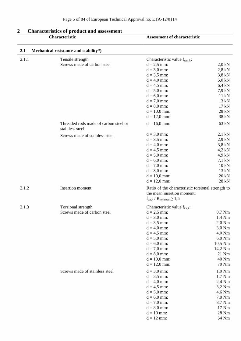
Characteristic value ftens,k: d = 2,5 mm: 2,0 kN d = 3,0 mm: 2,8 kN d = 3,5 mm: 3,8 kN d = 4,0 mm: 5,0 kN d = 4,5 mm: 6,4 kN d = 5,0 mm: 7,9 kN d = 6,0 mm: 11 kN d = 7,0 mm: 13 kN d = 8,0 mm: 17 kN d = 10,0 mm: 28 kN d = 12,0 mm: 38 kN
d = 16,0 mm: 63 kN
d = 3,0 mm: 2,1 kN d = 3,5 mm: 2,9 kN d = 4,0 mm: 3,8 kN d = 4,5 mm: 4,2 kN d = 5,0 mm: 4,9 kN d = 6,0 mm: 7,1 kN d = 7,0 mm: 10 kN d = 8,0 mm: 13 kN d = 10,0 mm: 20 kN d = 12,0 mm: 28 kN
2.1.2
Insertion moment Ratio of the characteristic torsional strength to the mean insertion moment: ftor,k / Rtor,mean > 1,5
2.1.3
Torsional strength Screws made of carbon steel
Screws made of stainless steel
Characteristic value ftor,k: d = 2,5 mm: 0,7 Nm d = 3,0 mm: 1,4 Nm d = 3,5 mm: 2,0 Nm d = 4,0 mm: 3,0 Nm d = 4,5 mm: 4,0 Nm d = 5,0 mm: 6,0 Nm d = 6,0 mm: 10,5 Nm d = 7,0 mm: 14,2 Nm d = 8,0 mm: 21 Nm d = 10,0 mm: 40 Nm d = 12,0 mm: 70 Nm
d = 3,0 mm: 1,0 Nm d = 3,5 mm: 1,7 Nm d = 4,0 mm: 2,4 Nm d = 4,5 mm: 3,2 Nm d = 5,0 mm: 4,6 Nm d = 6,0 mm: 7,0 Nm d = 7,0 mm: 8,7 Nm d = 8,0 mm: 17 Nm d = 10 mm: 28 Nm d = 12 mm: 54 Nm

Page 6 of 84 of European Technical Approval no. ETA-12/0114
Characteristic Assessment of characteristic
2.2 Safety in case of fire
2.2.1
Reaction to fire
The screws are made from steel classified as Euroclass A1 in accordance with EN 1350-1 and EC decision 96/603/EC, amended by EC Decision 2000/605/EC
2.3 Hygiene, health and the environment
2.3.1
Influence on air quality
No dangerous materials **)
2.4 Safety in use
Not relevant
2.5 Protection against noise
Not relevant
2.6 Energy economy and heat retention
Not relevant
2.7 Related aspects of serviceability
2.7.1
Durability
The screws have been assessed as having satisfactory durability and serviceability when used in timber structures using the timber species described in Eurocode 5 and subject to the conditions defined by service classes 1, 2 and 3
2.7.2
Serviceability
2.7.3
Identification
See Annex A
*) See page 4 of this ETA **) In accordance with http://europa.eu.int-/comm/enterprise/construction/internal/dangsub/dangmain.htm In addition to the specific clauses relating to dangerous substances contained in this European Technical Approval, there may be other requirements applicable to the products falling within its scope (e.g. transposed European legislation and national laws, regulations and administrative provisions). In order to meet the provisions of the EU Construction Products Directive, these requirements need also to be complied with, when and where they apply.
Page 7 of 84 of European Technical Approval no. ETA-12/0114
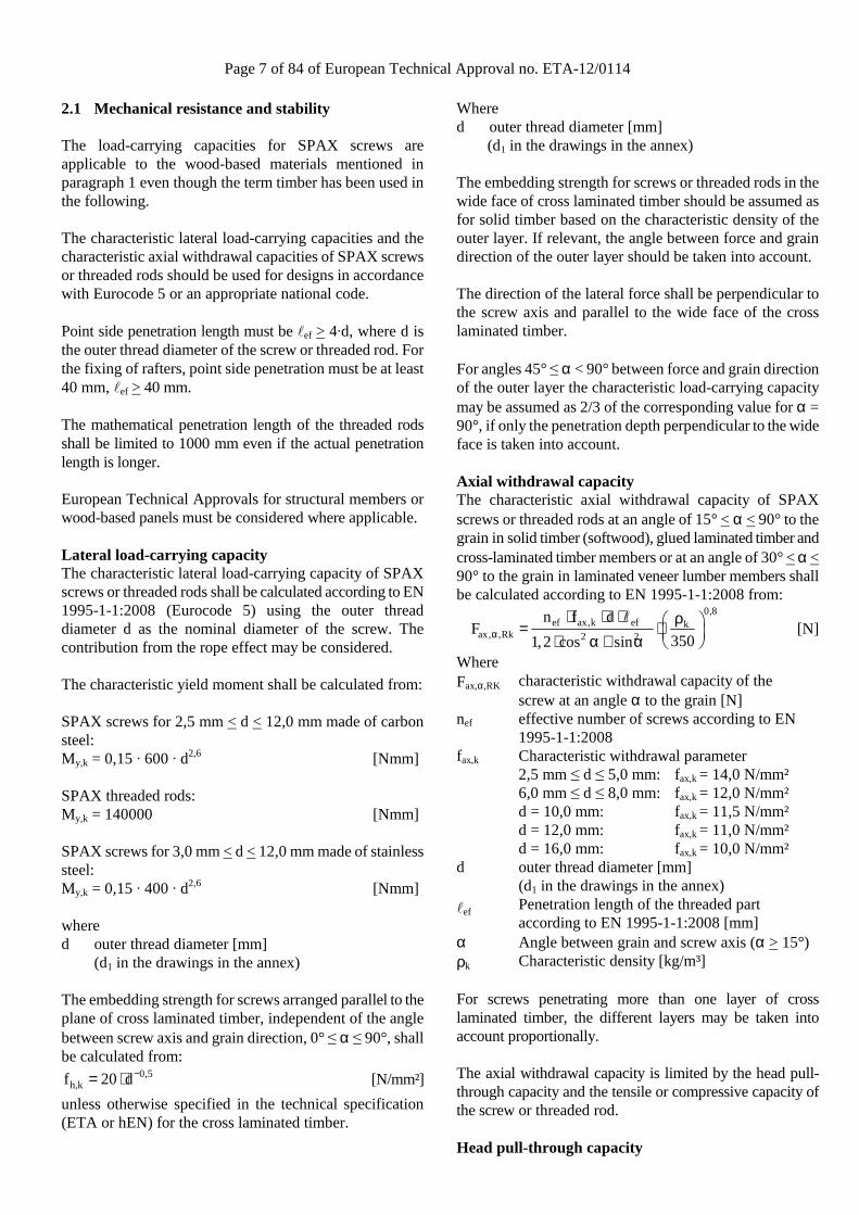
2.1 Mechanical resistance and stability The load-carrying capacities for SPAX screws are applicable to the wood-based materials mentioned in paragraph 1 even though the term timber has been used in the following. The characteristic lateral load-carrying capacities and the characteristic axial withdrawal capacities of SPAX screws or threaded rods should be used for designs in accordance with Eurocode 5 or an appropriate national code. Point side penetration length must be ℓef > 4·d, where d is the outer thread diameter of the screw or threaded rod. For the fixing of rafters, point side penetration must be at least 40 mm, ℓef > 40 mm. The mathematical penetration length of the threaded rods shall be limited to 1000 mm even if the actual penetration length is longer. European Technical Approvals for structural members or wood-based panels must be considered where applicable. Lateral load-carrying capacity The characteristic lateral load-carrying capacity of SPAX screws or threaded rods shall be calculated according to EN 1995-1-1:2008 (Eurocode 5) using the outer thread diameter d as the nominal diameter of the screw. The contribution from the rope effect may be considered. The characteristic yield moment shall be calculated from: SPAX screws for 2,5 mm < d < 12,0 mm made of carbon steel: My,k = 0,15 · 600 · d2,6 [Nmm] SPAX threaded rods: My,k = 140000 [Nmm] SPAX screws for 3,0 mm < d < 12,0 mm made of stainless steel: My,k = 0,15 · 400 · d2,6 [Nmm] where d outer thread diameter [mm] (d1 in the drawings in the annex) The embedding strength for screws arranged parallel to the plane of cross laminated timber, independent of the angle between screw axis and grain direction, 0° ≤ α ≤ 90°, shall be calculated from:
0,5h,kf 20 d−= ⋅ [N/mm²]
unless otherwise specified in the technical specification (ETA or hEN) for the cross laminated timber.
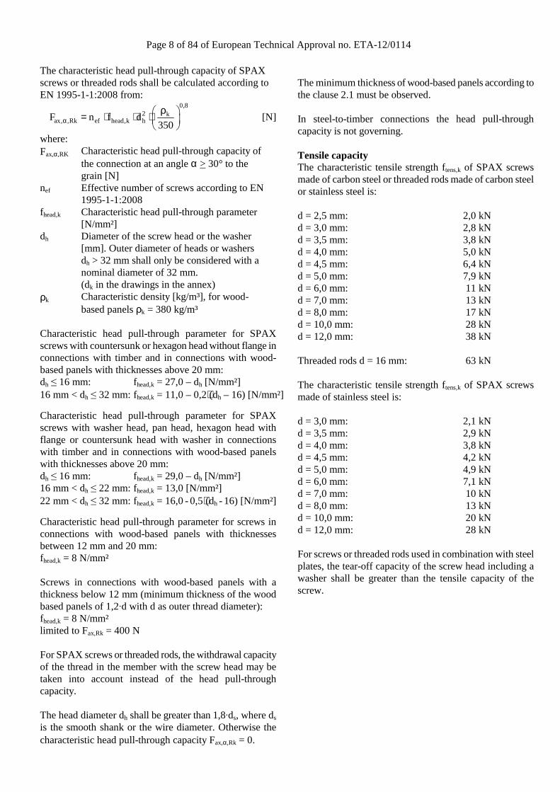
Where d outer thread diameter [mm] (d1 in the drawings in the annex) The embedding strength for screws or threaded rods in the wide face of cross laminated timber should be assumed as for solid timber based on the characteristic density of the outer layer. If relevant, the angle between force and grain direction of the outer layer should be taken into account. The direction of the lateral force shall be perpendicular to the screw axis and parallel to the wide face of the cross laminated timber. For angles 45° ≤ α < 90° between force and grain direction of the outer layer the characteristic load-carrying capacity may be assumed as 2/3 of the corresponding value for α = 90°, if only the penetration depth perpendicular to the wide face is taken into account. Axial withdrawal capacity The characteristic axial withdrawal capacity of SPAX screws or threaded rods at an angle of 15° < α < 90° to the grain in solid timber (softwood), glued laminated timber and cross-laminated timber members or at an angle of 30° < α < 90° to the grain in laminated veneer lumber members shall be calculated according to EN 1995-1-1:2008 from:
0,8
ef ax,k ef kax, ,Rk 2 2
n f dF
3501,2 cos sinα
⋅ ⋅ ⋅ ρ = ⋅ ⋅ α + α
ℓ [N]
Where Fax,α,RK characteristic withdrawal capacity of the
screw at an angle α to the grain [N] nef effective number of screws according to EN
1995-1-1:2008 fax,k Characteristic withdrawal parameter
2,5 mm ≤ d ≤ 5,0 mm: fax,k = 14,0 N/mm² 6,0 mm ≤ d ≤ 8,0 mm: fax,k = 12,0 N/mm² d = 10,0 mm: fax,k = 11,5 N/mm² d = 12,0 mm: fax,k = 11,0 N/mm² d = 16,0 mm: fax,k = 10,0 N/mm²
d outer thread diameter [mm] (d1 in the drawings in the annex)
ℓef Penetration length of the threaded part according to EN 1995-1-1:2008 [mm]
α Angle between grain and screw axis (α > 15°) ρk Characteristic density [kg/m³] For screws penetrating more than one layer of cross laminated timber, the different layers may be taken into account proportionally. The axial withdrawal capacity is limited by the head pull-through capacity and the tensile or compressive capacity of the screw or threaded rod. Head pull-through capacity
Page 8 of 84 of European Technical Approval no. ETA-12/0114
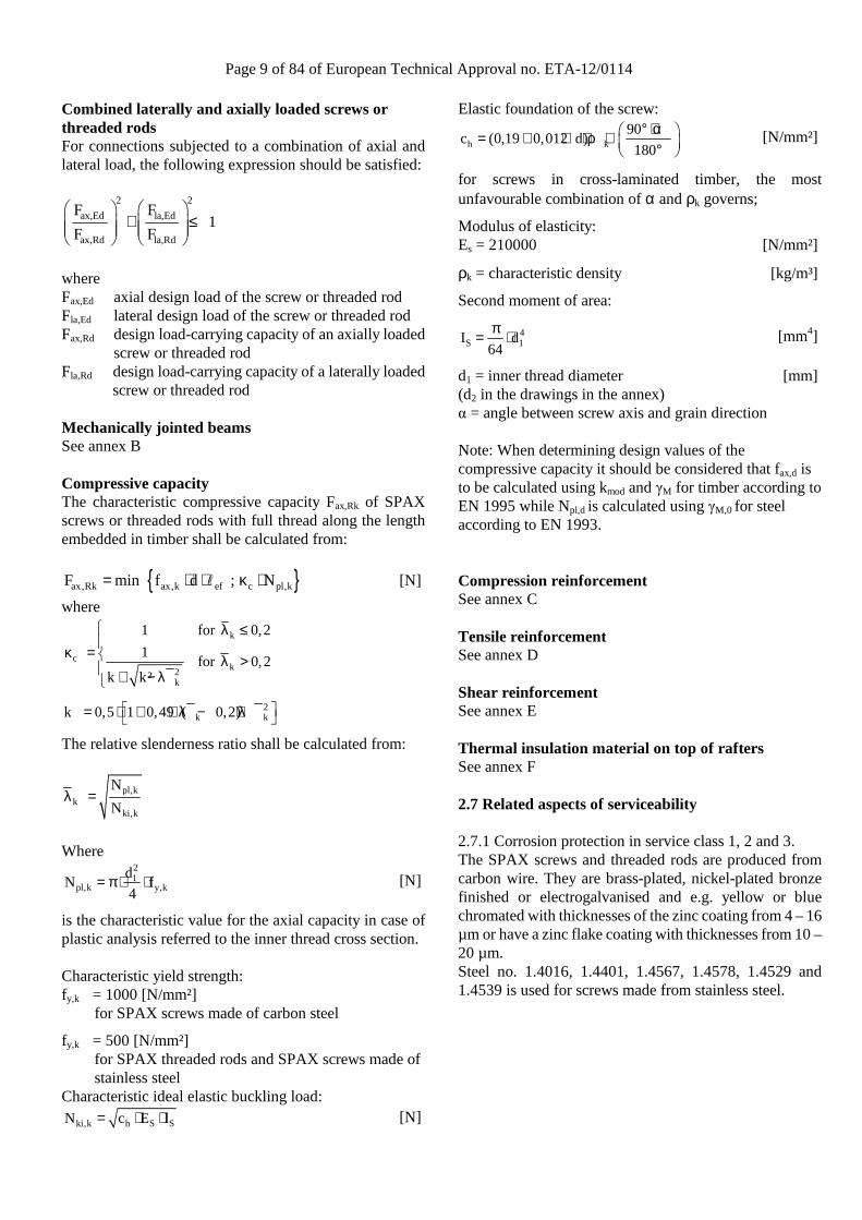
The characteristic head pull-through capacity of SPAX screws or threaded rods shall be calculated according to EN 1995-1-1:2008 from:
0,8
2 kax, ,Rk ef head,k hF n f d
350αρ = ⋅ ⋅ ⋅
[N]
where: Fax,α,RK Characteristic head pull-through capacity of
the connection at an angle α > 30° to the grain [N]
nef Effective number of screws according to EN 1995-1-1:2008
fhead,k Characteristic head pull-through parameter [N/mm²]
dh Diameter of the screw head or the washer [mm]. Outer diameter of heads or washers dh > 32 mm shall only be considered with a nominal diameter of 32 mm. (dk in the drawings in the annex)
ρk Characteristic density [kg/m³], for wood-based panels ρk = 380 kg/m³
Characteristic head pull-through parameter for SPAX screws with countersunk or hexagon head without flange in connections with timber and in connections with wood-based panels with thicknesses above 20 mm: dh ≤ 16 mm: fhead,k = 27,0 – dh [N/mm²] 16 mm < dh ≤ 32 mm: fhead,k = 11,0 – 0,2⋅(dh – 16) [N/mm²]
Characteristic head pull-through parameter for SPAX screws with washer head, pan head, hexagon head with flange or countersunk head with washer in connections with timber and in connections with wood-based panels with thicknesses above 20 mm: dh ≤ 16 mm: fhead,k = 29,0 – dh [N/mm²] 16 mm < dh ≤ 22 mm: fhead,k = 13,0 [N/mm²] 22 mm < dh ≤ 32 mm: fhead,k = 16,0 - 0,5⋅(dh - 16) [N/mm²]
Characteristic head pull-through parameter for screws in connections with wood-based panels with thicknesses between 12 mm and 20 mm: fhead,k = 8 N/mm² Screws in connections with wood-based panels with a thickness below 12 mm (minimum thickness of the wood based panels of 1,2·d with d as outer thread diameter): fhead,k = 8 N/mm² limited to Fax,Rk = 400 N For SPAX screws or threaded rods, the withdrawal capacity of the thread in the member with the screw head may be taken into account instead of the head pull-through capacity. The head diameter dh shall be greater than 1,8·ds, where ds is the smooth shank or the wire diameter. Otherwise the characteristic head pull-through capacity Fax,α,Rk = 0.
The minimum thickness of wood-based panels according to the clause 2.1 must be observed. In steel-to-timber connections the head pull-through capacity is not governing. Tensile capacity The characteristic tensile strength ftens,k of SPAX screws made of carbon steel or threaded rods made of carbon steel or stainless steel is: d = 2,5 mm: 2,0 kN d = 3,0 mm: 2,8 kN d = 3,5 mm: 3,8 kN d = 4,0 mm: 5,0 kN d = 4,5 mm: 6,4 kN d = 5,0 mm: 7,9 kN d = 6,0 mm: 11 kN d = 7,0 mm: 13 kN d = 8,0 mm: 17 kN d = 10,0 mm: 28 kN d = 12,0 mm: 38 kN Threaded rods d = 16 mm: 63 kN The characteristic tensile strength ftens,k of SPAX screws made of stainless steel is: d = 3,0 mm: 2,1 kN d = 3,5 mm: 2,9 kN d = 4,0 mm: 3,8 kN d = 4,5 mm: 4,2 kN d = 5,0 mm: 4,9 kN d = 6,0 mm: 7,1 kN d = 7,0 mm: 10 kN d = 8,0 mm: 13 kN d = 10,0 mm: 20 kN d = 12,0 mm: 28 kN For screws or threaded rods used in combination with steel plates, the tear-off capacity of the screw head including a washer shall be greater than the tensile capacity of the screw.
Page 9 of 84 of European Technical Approval no. ETA-12/0114
Combined laterally and axially loaded screws or threaded rods For connections subjected to a combination of axial and lateral load, the following expression should be satisfied:
2 2
ax,Ed la,Ed
ax,Rd la,Rd
F F1
F F
+ ≤
where Fax,Ed axial design load of the screw or threaded rod Fla,Ed lateral design load of the screw or threaded rod Fax,Rd design load-carrying capacity of an axially loaded
screw or threaded rod Fla,Rd design load-carrying capacity of a laterally loaded
screw or threaded rod Mechanically jointed beams See annex B Compressive capacity The characteristic compressive capacity Fax,Rk of SPAX screws or threaded rods with full thread along the length embedded in timber shall be calculated from:
{ }ax,Rk ax,k ef c pl,kF min f d ; N= ⋅ ⋅ κ ⋅ℓ [N]
where
k
ck2
k
1 for 0,2
1for 0,2
k k²
λ ≤
κ = λ > + − λ
2k kk 0,5 1 0,49 ( 0,2) = ⋅ + ⋅ λ − + λ
The relative slenderness ratio shall be calculated from:
pl,kk
ki,k
N
Nλ =
Where
21
pl,k y,kd
N f4
= π ⋅ ⋅ [N]
is the characteristic value for the axial capacity in case of plastic analysis referred to the inner thread cross section. Characteristic yield strength: fy,k = 1000 [N/mm²]
for SPAX screws made of carbon steel
fy,k = 500 [N/mm²] for SPAX threaded rods and SPAX screws made of stainless steel
Characteristic ideal elastic buckling load:
ki,k h S SN c E I= ⋅ ⋅ [N]
Elastic foundation of the screw:
h k90
c (0,19 0,012 d)180
° + α = + ⋅ ⋅ρ ⋅ ° [N/mm²]
for screws in cross-laminated timber, the most unfavourable combination of α and ρk governs;
Modulus of elasticity: Es = 210000 [N/mm²]
ρk = characteristic density [kg/m³]
Second moment of area:
4S 1I d
64
π= ⋅ [mm4]
d1 = inner thread diameter [mm] (d2 in the drawings in the annex) α = angle between screw axis and grain direction Note: When determining design values of the compressive capacity it should be considered that fax,d is to be calculated using kmod and γM for timber according to EN 1995 while Npl,d is calculated using γM,0 for steel according to EN 1993. Compression reinforcement See annex C Tensile reinforcement See annex D Shear reinforcement See annex E Thermal insulation material on top of rafters See annex F 2.7 Related aspects of serviceability 2.7.1 Corrosion protection in service class 1, 2 and 3. The SPAX screws and threaded rods are produced from carbon wire. They are brass-plated, nickel-plated bronze finished or electrogalvanised and e.g. yellow or blue chromated with thicknesses of the zinc coating from 4 – 16 µm or have a zinc flake coating with thicknesses from 10 – 20 µm. Steel no. 1.4016, 1.4401, 1.4567, 1.4578, 1.4529 and 1.4539 is used for screws made from stainless steel.

Page 10 of 84 of European Technical Approval no. ETA-12/0114
3 Attestation of Conformity and CE marking
3.1 Attestation of Conformity system The system of attestation of conformity is 2+
described in Council Directive 89/106/EEC (Construction Products Directive) Annex III.
a) Tasks for the manufacturer:
(1) Factory production control, (2) Initial type testing of the product,
b) Tasks for the notified body: (1) Initial inspection of the factory and the
factory production control, (2) Continuous surveillance 3.2 Responsibilities 3.2.1 Tasks of the manufacturer 3.2.1.1 Factory production control
The manufacturer has a factory production control system in the plant and exercises permanent internal control of production. All the elements, requirements and provisions adopted by the manufacturer are documented in a systematic manner in the form of written policies and procedures. This production control system ensures that the product is in conformity with the European Technical Approval. The manufacturer shall only use raw materials supplied with the relevant inspection documents as laid down in the control plan4. The incoming raw materials shall be subject to controls and tests by the manufacturer before acceptance. Check of raw materials, such as metal wire, shall include control of the inspection documents presented by suppliers (comparison with nominal values) by verifying dimension and determining material properties. The manufactured components shall be subject to the following checks: - Raw material specification; - Dimension of the screws or threaded rods; - Characteristic tensile strength ftens,k; - Characteristic torsional strength ftor,k;
4 The control plan has been deposited at ETA-Danmark and is only made available to the approved bodies involved in the conformity attestation procedure.
- Characteristic insertion moment Rtor,k; - Durability; - Marking.
The control plan, which is part of the technical documentation of this European Technical Approval, includes details of the extent, nature and frequency of testing and controls to be performed within the factory production control and has been agreed between the approval holder and ETA Danmark. The results of factory production control are recorded and evaluated. The records include at least the following information: - Designation of the product, basic material and
components; - Type of control or testing; - Date of manufacture of the product and date of
testing of the product or basic material and components;
- Result of control and testing and, if appropriate, comparison with requirements;
- Signature of person responsible for factory production control.
The records shall be presented to ETA Danmark on request.
3.2.1.1 Initial type testing of the product
For initial type-testing the results of the tests performed as part of the assessment for the European Technical Approval shall be used unless there are changes in the production line or plant. In such cases the necessary initial type testing has to be agreed between ETA Danmark and the notified body. The initial type testing shall be subject to the following checks: - Raw material specification; - Dimension of the screws or threaded rods; - Characteristic yield moment My,k; - Characteristic withdrawal parameter fax,k; - Characteristic head pull-through parameter fhead,k; - Characteristic tensile strength ftens,k; - Characteristic yield strength if relevant; - Characteristic torsional strength ftor,k; - Characteristic insertion moment Rtor,k; - Durability.
3.2.2. Tasks of notified bodies 3.2.2.1 Initial inspection of the factory and the factory production control
Page 11 of 84 of European Technical Approval no. ETA-12/0114
The approved body should ascertain that, in accordance with the control plan, the factory, in particular the staff and equipment, and the factory production control, are suitable to ensure a continuous and orderly manufacturing of the screws with the specifications given in part 2.
3.2.2.2 Continuous surveillance
The approved body shall visit the factory at least once a year for routine inspections. It shall be verified that the system of factory production control and the specified manufacturing processes are maintained, taking account of the control plan.
The results of product certification and continuous surveillance shall be made available on demand by the certification body to ETA Danmark. Where the provisions of the European Technical Approval and the control plan are no longer fulfilled, the certificate of conformity shall be withdrawn by the approved body.
3.3 CE marking The CE marking shall be affixed on each packaging of screws. The initials "CE" shall be followed by the identification number of the notified body and shall be accompanied by the following information:
- Name or identifying mark of the manufacturer
- The last two digits of the year in which the marking was affixed
- Number of the European Technical Approval
- Name of product - Outer thread diameter and length of the
self-tapping screws - Type and mean thickness of the corrosion
protection, if relevant - Stainless steel including the material
number, if relevant - Number of the EC Certificate of
Conformity

Page 12 of 84 of European Technical Approval no. ETA-12/0114
4 Assumptions under which the fitness of the product for the intended use was favourably assessed 4.1 Manufacturing The screws or threaded rods are manufactured in accordance with the provisions of the European Technical Approval using the automated manufacturing process as identified during the inspection of the plant by the approval body issuing the ETA and the approved body and laid down in the technical documentation.
4.2 Installation 4.2.1 The installation shall be carried out in accordance with Eurocode 5 or an appropriate national code unless otherwise is defined in the following. Instructions from SPAX International GmbH & Co. KG should be considered for installation.
4.2.2 The screws or threaded rods are used for connections in load bearing timber structures between members of solid timber (softwood), glued laminated timber, cross-laminated timber (minimum diameter d = 6,0 mm), and laminated veneer lumber, similar glued members, wood-based panels or steel members. To connect cross-laminated timber the inner thread diameter d1 of the screws shall be greater than the maximal width of the gaps in the layer.
The screws or threaded rods may be used for connections in load bearing timber structures with structural members according to an associated European Technical Approval, if according to the associated European Technical Approval of the structural member a connection in load bearing timber structures with screws according to a European Technical Approval is allowed.
SPAX fully threaded screws or threaded rods are also used as tensile or compressive reinforcement perpendicular to the grain or as shear reinforcement.
Furthermore the screws with diameters between 6 mm and 12 mm may also be used for the fixing of insulation on top of rafters.
A minimum of two screws or threaded rods should be used for connections in load bearing timber structures.
The minimum penetration depth in structural members made of solid, glued or cross-laminated timber is 4·d.
Wood-based panels and steel plates should only be arranged on the side of the screw head. The minimum thickness of wood-based panels should be 1,2·d. Furthermore the minimum thickness for following wood-based panels should be:
• Plywood, Fibreboards: 6 mm • Particleboards, OSB, Cement Particleboards: 8 mm
• Solid wood panels: 12 mm
For structural members according to European Technical Approvals the terms of the European Technical Approvals must be considered.
If screws with an outer thread diameter d > 8 mm are used in load bearing timber structures, the structural solid or glued laminated timber, laminated veneer lumber and similar glued members must be from spruce, pine or fir. This does not apply for screws or threaded rods in pre-drilled holes.
The minimum angle between the screw axis and the grain direction is α = 15°.
4.2.3 The screws shall be driven into softwood without predrilling or after pre-drilling with a diameter not larger than the inner thread diameter for the length of the threaded part and with a maximum of the smooth shank diameter for the length of the smooth shank. The threaded rods shall be driven into softwood after pre-drilling with the following diameters: Threaded rod 16 mm Pre-drilling diameter 13 mm Threaded rod shall only be driven into pre-drilled holes The hole diameter in steel members must be predrilled with a suitable diameter.
Only the equipment prescribed by SPAX GmbH & Co. KG shall be used for driving the screws.
In connections with screws with countersunk head according to Annex A the head must be flush with the surface of the connected structural member. A deeper countersink is not allowed.
4.2.4 Unless otherwise specified, minimum thickness for non-predrilled structural members is t = 24 mm for screws with outer thread diameter d < 8 mm, t = 30 mm for screws with outer thread diameter d = 8 mm, t = 40 mm for screws with outer thread diameter d = 10 mm and t = 80 mm for screws with outer thread diameter d = 12 mm. For structural timber members, minimum spacing and distances for screws in predrilled holes are given in EN 1995-1-1:2008 (Eurocode 5) clause 8.3.1.2 and table 8.2 as for nails in predrilled holes. These minimum spacing and distances also apply for SPAX screws with CUT or 4CUT drill tip in non-predrilled holes. Here, the outer thread diameter d must be considered. For SPAX screws with CUT or 4CUT drill tip in non-predrilled holes the following conditions shall be fulfilled: • a1 ≥ 5·d
• a3,c ≥ 12·d
• a3,t ≥ 12·d
• minimum cross-section ≥ 40 d²
Page 13 of 84 of European Technical Approval no. ETA-12/0114
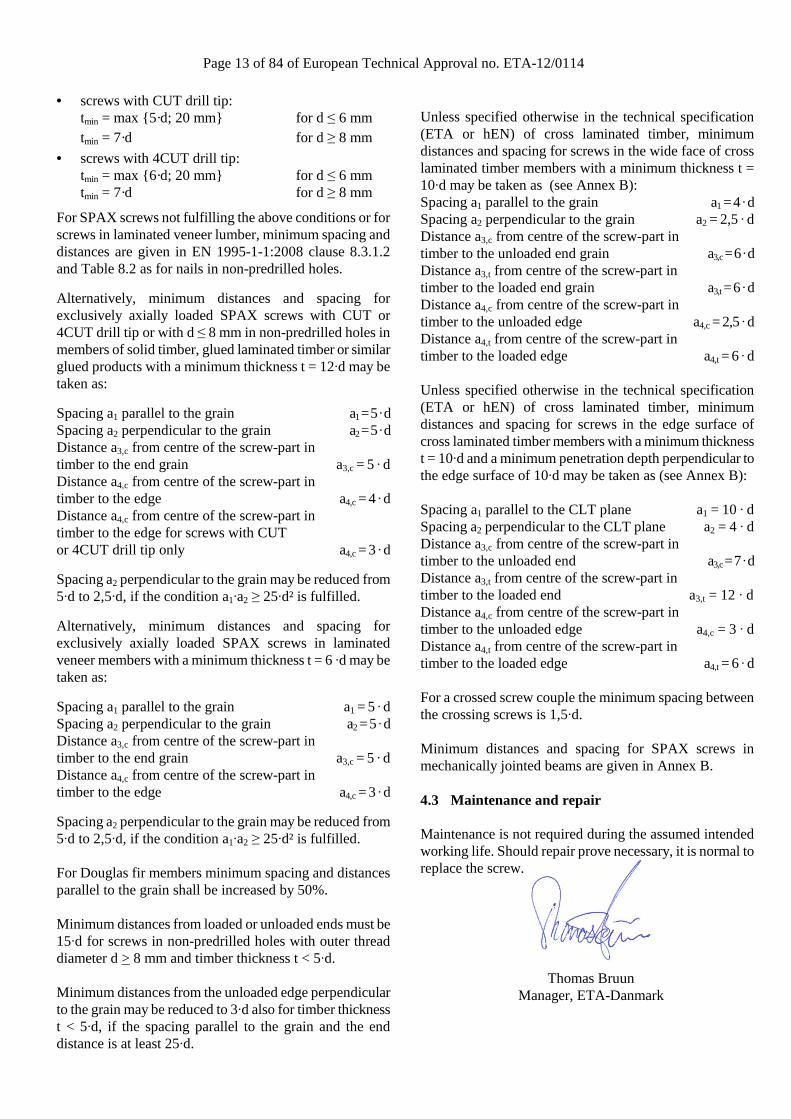
• screws with CUT drill tip: tmin = max {5·d; 20 mm} for d ≤ 6 mm tmin = 7·d for d ≥ 8 mm
• screws with 4CUT drill tip: tmin = max {6·d; 20 mm} for d ≤ 6 mm tmin = 7·d for d ≥ 8 mm
For SPAX screws not fulfilling the above conditions or for screws in laminated veneer lumber, minimum spacing and distances are given in EN 1995-1-1:2008 clause 8.3.1.2 and Table 8.2 as for nails in non-predrilled holes.
Alternatively, minimum distances and spacing for exclusively axially loaded SPAX screws with CUT or 4CUT drill tip or with d ≤ 8 mm in non-predrilled holes in members of solid timber, glued laminated timber or similar glued products with a minimum thickness t = 12·d may be taken as:
Spacing a1 parallel to the grain a1 = 5 · d Spacing a2 perpendicular to the grain a2 = 5 · d Distance a3,c from centre of the screw-part in timber to the end grain a3,c = 5 · d Distance a4,c from centre of the screw-part in timber to the edge a4,c = 4 · d Distance a4,c from centre of the screw-part in timber to the edge for screws with CUT or 4CUT drill tip only a4,c = 3 · d
Spacing a2 perpendicular to the grain may be reduced from 5·d to 2,5·d, if the condition a1·a2 ≥ 25·d² is fulfilled.
Alternatively, minimum distances and spacing for exclusively axially loaded SPAX screws in laminated veneer members with a minimum thickness t = 6 ·d may be taken as:
Spacing a1 parallel to the grain a1 = 5 · d Spacing a2 perpendicular to the grain a2 = 5 · d Distance a3,c from centre of the screw-part in timber to the end grain a3,c = 5 · d Distance a4,c from centre of the screw-part in timber to the edge a4,c = 3 · d
Spacing a2 perpendicular to the grain may be reduced from 5·d to 2,5·d, if the condition a1·a2 ≥ 25·d² is fulfilled. For Douglas fir members minimum spacing and distances parallel to the grain shall be increased by 50%. Minimum distances from loaded or unloaded ends must be 15·d for screws in non-predrilled holes with outer thread diameter d > 8 mm and timber thickness t < 5·d. Minimum distances from the unloaded edge perpendicular to the grain may be reduced to 3·d also for timber thickness t < 5·d, if the spacing parallel to the grain and the end distance is at least 25·d.
Unless specified otherwise in the technical specification (ETA or hEN) of cross laminated timber, minimum distances and spacing for screws in the wide face of cross laminated timber members with a minimum thickness t = 10·d may be taken as (see Annex B): Spacing a1 parallel to the grain a1 = 4 · d Spacing a2 perpendicular to the grain a2 = 2,5 · d Distance a3,c from centre of the screw-part in timber to the unloaded end grain a3,c = 6 · d Distance a3,t from centre of the screw-part in timber to the loaded end grain a3,t = 6 · d Distance a4,c from centre of the screw-part in timber to the unloaded edge a4,c = 2,5 · d Distance a4,t from centre of the screw-part in timber to the loaded edge a4,t = 6 · d Unless specified otherwise in the technical specification (ETA or hEN) of cross laminated timber, minimum distances and spacing for screws in the edge surface of cross laminated timber members with a minimum thickness t = 10·d and a minimum penetration depth perpendicular to the edge surface of 10·d may be taken as (see Annex B): Spacing a1 parallel to the CLT plane a1 = 10 · d Spacing a2 perpendicular to the CLT plane a2 = 4 · d Distance a3,c from centre of the screw-part in timber to the unloaded end a3,c = 7 · d Distance a3,t from centre of the screw-part in timber to the loaded end a3,t = 12 · d Distance a4,c from centre of the screw-part in timber to the unloaded edge a4,c = 3 · d Distance a4,t from centre of the screw-part in timber to the loaded edge a4,t = 6 · d For a crossed screw couple the minimum spacing between the crossing screws is 1,5·d. Minimum distances and spacing for SPAX screws in mechanically jointed beams are given in Annex B. 4.3 Maintenance and repair Maintenance is not required during the assumed intended working life. Should repair prove necessary, it is normal to replace the screw.
Thomas Bruun Manager, ETA-Danmark

Page 14 of 84 of European Technical Approval no. ETA-12/0114
Annex A Drawings, designation and material specification of SPAX screws
Nominal diameterd1 thread size 2,5 3,0 3,5 4,0 4,5 5,0 6,0 permissible tolerancedk head diameter 5,1 6,0 7,0 8,0 8,8 9,7 11,6 permissible tolerance -0,43d2 core diameter 1,7 2,0 2,2 2,5 2,8 3,1 3,8
permissible tolerance -0,25 -0,30ds shank diameter 1,8 2,15 2,45 2,85 3,20 3,55 4,30
permissible tolerancek head height max. 1,6 1,8 2,1 2,4 2,7 2,9 3,4p thread pitch 1,3 1,5 1,8 2,0 2,2 2,5 3,0 permissible toleranceT-STAR size T8 T10 T15 T20 T25 T30Cross recess size Type Z
Ls Standard thread lengths ( full thread = lgV / partial thread = lgT )Nom.dim. min max lgV lgT lgV lgT lgV lgT lgV lgT lgV lgT lgV lgT lgV lgT
12 12,0 13,5 10,015 14,0 15,5 12,0 12,516 16,0 17,5 14,0 14,020 18,5 20,5 17,0 12,0 17,0 16,0 16,025 23,5 25,5 22,0 18,0 21,0 18,0 21,0 18,0 21,0 20,0 20,030 28,5 30,5 27,0 18,0 26,0 18,0 25,0 18,0 25,0 18,0 25,0 25,0 24,035 33,5 36,0 22,0 31,0 23,0 30,0 23,0 30,0 23,0 30,0 25,0 30,0 25,0 29,0 24,040 38,5 41,0 22,0 36,0 23,0 35,0 23,0 35,0 23,0 34,0 25,0 35,0 27,0 34,0 24,045 43,5 46,0 28,0 28,0 40,0 30,0 40,0 30,0 39,0 30,0 39,0 30,0 38,0 29,050 48,5 51,0 28,0 40,0 32,0 45,0 32,0 44,0 32,0 44,0 32,0 43,0 32,055 53,5 56,0 36,0 35,0 50,0 35,0 49,0 37,0 49,0 37,0 48,0 37,060 58,5 61,0 35,0 50,0 35,0 54,0 37,0 54,0 37,0 53,0 37,065 63,5 66,0 40,0 37,5 59,0 42,0 59,0 41,0 58,0 41,070 68,5 71,0 37,5 59,0 42,0 61,0 41,0 61,0 41,075 73,5 76,0 37,5 42,0 61,0 41,0 61,0 41,080 78,5 81,0 37,5 47,0 61,0 46,0 61,0 46,090 88,5 91,5 47,0 61,0 61,0100 98,5 101,5 61,0 61,0110 108,5 111,5 69,0 68,0120 118,5 121,5 69,0 68,0130 128,0 132,0 68,0140 138,0 142,0 68,0150 148,0 152,0 68,0160 158,0 162,0 68,0
Screws of Ø6,0mm with partial thread additionally in lenght Other thread lengths in the range ≥4xd1of 180 to 300mm, in steps of 20mm, LgT= 68,0 mm to max. standard length permitted.
Intermediate lengths on Ls possible
Annex A1
Flat countersunk head
1 2 3
±0,15
±0,10
±0,1 x p
4,02,5 3,5 4,5 5,0 6,0
Self-drilling screw with full and partial threadMaterial: cold rolled wire according to SPAX - Factory Standard
Screws of high carbon steel
3,0
-0,40
Page 15 of 84 of European Technical Approval no. ETA-12/0114
d1 thread size permissible tolerancedk head diameter permissible toleranced2 core diameter
permissible toleranceds shank diameter
permissible tolerancek head height max.p thread pitch permissible toleranceT - STAR sizeCross recess size Type Z
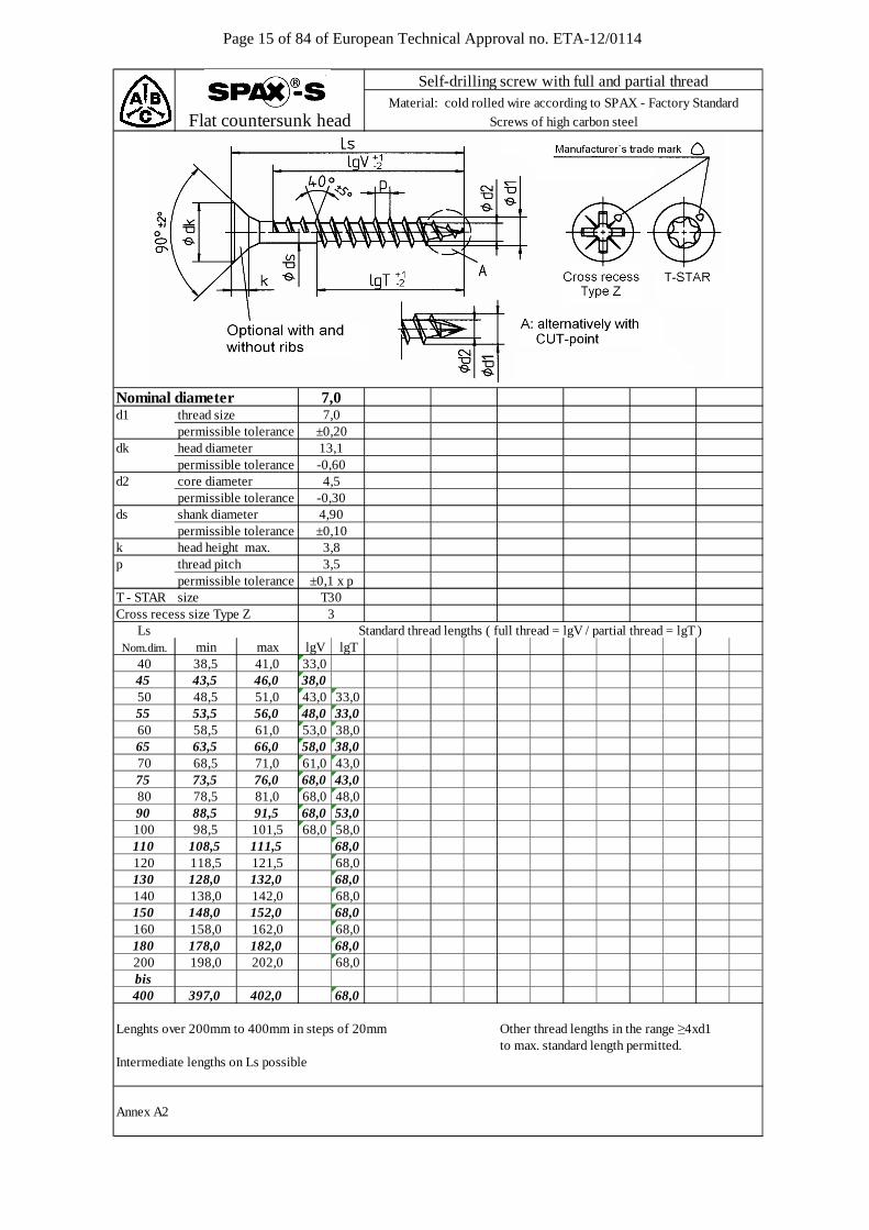
Ls Standard thread lengths ( full thread = lgV / partial thread = lgT )Nom.dim. min max lgV lgT
40 38,5 41,0 33,045 43,5 46,0 38,050 48,5 51,0 43,0 33,055 53,5 56,0 48,0 33,060 58,5 61,0 53,0 38,065 63,5 66,0 58,0 38,070 68,5 71,0 61,0 43,075 73,5 76,0 68,0 43,080 78,5 81,0 68,0 48,090 88,5 91,5 68,0 53,0100 98,5 101,5 68,0 58,0110 108,5 111,5 68,0120 118,5 121,5 68,0130 128,0 132,0 68,0140 138,0 142,0 68,0150 148,0 152,0 68,0160 158,0 162,0 68,0180 178,0 182,0 68,0200 198,0 202,0 68,0bis 400 397,0 402,0 68,0
Lenghts over 200mm to 400mm in steps of 20mm Other thread lengths in the range ≥4xd1to max. standard length permitted.
Intermediate lengths on Ls possible
Annex A2
13,1
T303
±0,103,83,5
±0,1 x p
-0,604,5
-0,30
Self-drilling screw with full and partial threadMaterial: cold rolled wire according to SPAX - Factory Standard
Screws of high carbon steelFlat countersunk head
Nominal diameter 7,0
4,90
7,0±0,20
Page 16 of 84 of European Technical Approval no. ETA-12/0114
d1 thread size permissible tolerancedk head diameter permissible tolerancedk1 contersink diameter
permissible toleranced2 core diameter
permissible toleranceds shank diameter 2,45
permissible tolerancek head height max.p thread pitch permissible toleranceT - STAR sizeCross recess size Type Z
LsNom.dim. min max lgV lgT lgV lgT lgV lgT lgV lgT lgV lgT lgV lgT
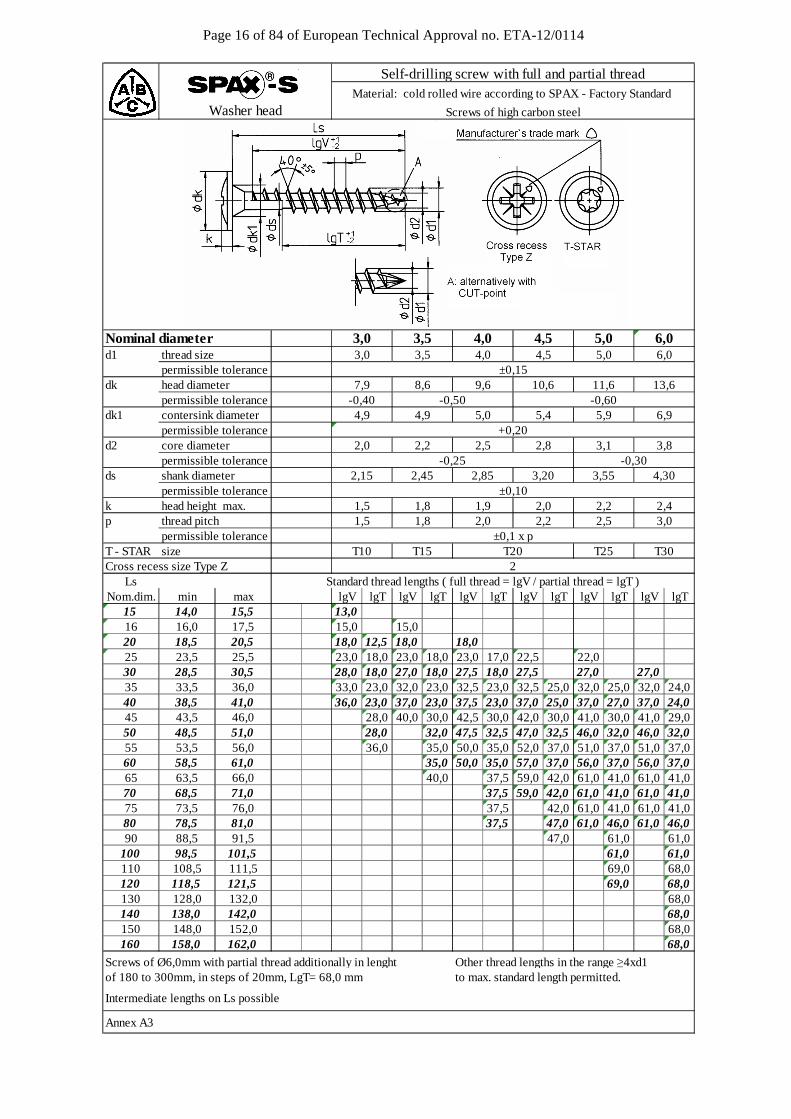
15 14,0 15,5 13,016 16,0 17,5 15,0 15,020 18,5 20,5 18,0 12,5 18,0 18,025 23,5 25,5 23,0 18,0 23,0 18,0 23,0 17,0 22,5 22,030 28,5 30,5 28,0 18,0 27,0 18,0 27,5 18,0 27,5 27,0 27,035 33,5 36,0 33,0 23,0 32,0 23,0 32,5 23,0 32,5 25,0 32,0 25,0 32,0 24,040 38,5 41,0 36,0 23,0 37,0 23,0 37,5 23,0 37,0 25,0 37,0 27,0 37,0 24,045 43,5 46,0 28,0 40,0 30,0 42,5 30,0 42,0 30,0 41,0 30,0 41,0 29,050 48,5 51,0 28,0 32,0 47,5 32,5 47,0 32,5 46,0 32,0 46,0 32,055 53,5 56,0 36,0 35,0 50,0 35,0 52,0 37,0 51,0 37,0 51,0 37,060 58,5 61,0 35,0 50,0 35,0 57,0 37,0 56,0 37,0 56,0 37,065 63,5 66,0 40,0 37,5 59,0 42,0 61,0 41,0 61,0 41,070 68,5 71,0 37,5 59,0 42,0 61,0 41,0 61,0 41,075 73,5 76,0 37,5 42,0 61,0 41,0 61,0 41,080 78,5 81,0 37,5 47,0 61,0 46,0 61,0 46,090 88,5 91,5 47,0 61,0 61,0
100 98,5 101,5 61,0 61,0110 108,5 111,5 69,0 68,0120 118,5 121,5 69,0 68,0130 128,0 132,0 68,0140 138,0 142,0 68,0150 148,0 152,0 68,0160 158,0 162,0 68,0
Screws of Ø6,0mm with partial thread additionally in lenght Other thread lengths in the range ≥4xd1of 180 to 300mm, in steps of 20mm, LgT= 68,0 mm to max. standard length permitted.
Intermediate lengths on Ls possible
Annex A3
Self-drilling screw with full and partial threadMaterial: cold rolled wire according to SPAX - Factory Standard
Screws of high carbon steel
6,9
2,8 3,1 3,8
5,9
4,0 4,5
Washer head
3,0±0,1 x p
2
2,01,8 2,2 2,5
4,30
2,41,9 2,0±0,10
2,85 3,20 3,55
5,0
2,2
9,6-0,60
+0,20
-0,25 -0,302,5
3,5
4,9
3,0±0,15
-0,505,0
6,0
4,9
2,2
1,8
3,0 3,5 4,0 4,5
2,0
2,15
1,51,5
T10
13,6-0,40
10,6 11,68,67,9
6,0
Standard thread lengths ( full thread = lgV / partial thread = lgT )
Nominal diameter 5,0
T15 T20 T25 T30
5,4
Page 17 of 84 of European Technical Approval no. ETA-12/0114
Norminal diameterd1 thread size permissible tolerancedk head diameter permissible tolerancedk1 contersink diameter
permissible toleranced2 core diameter
permissible toleranceds shank diameter
permissible tolerancek head height max. p thread pitch permissible toleranceT - STAR sizeCross recess size Type Z
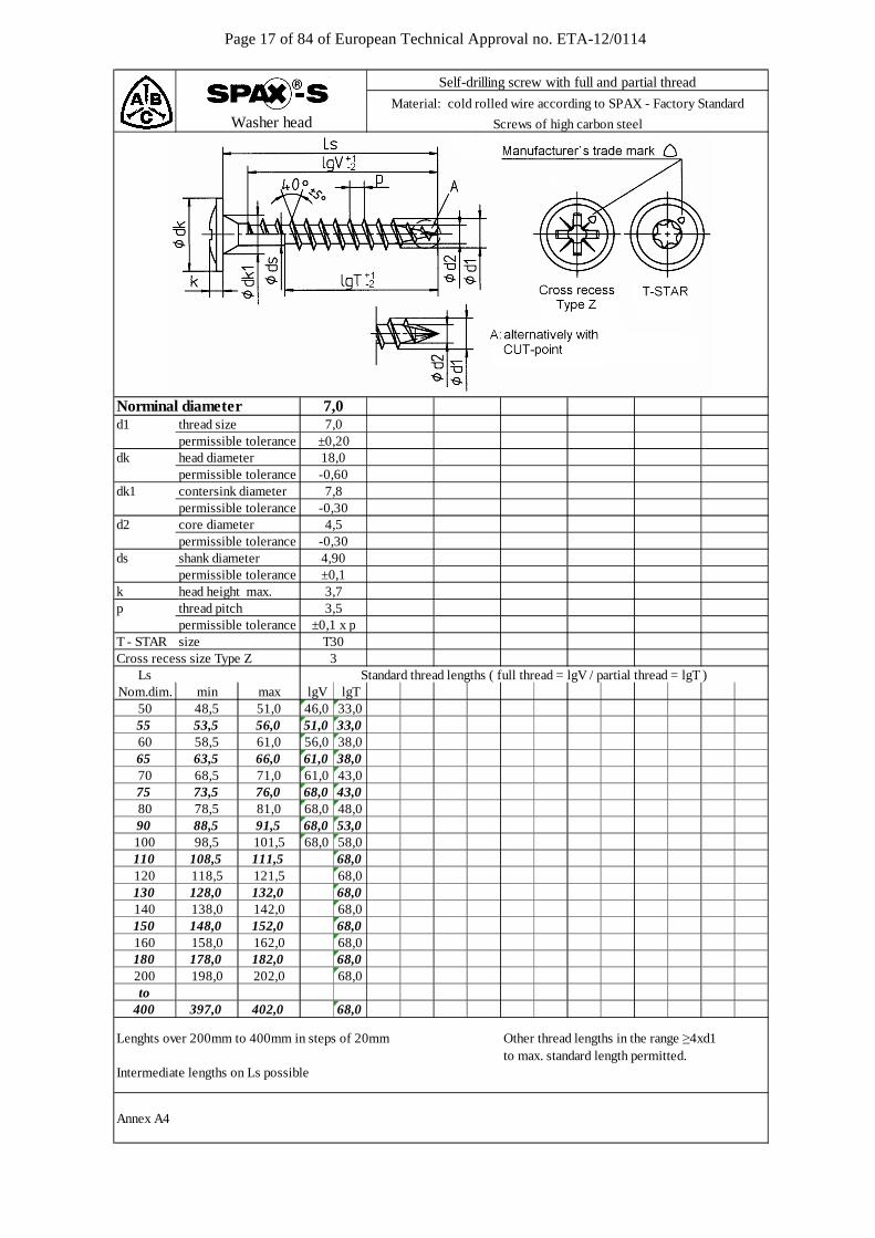
Ls Standard thread lengths ( full thread = lgV / partial thread = lgT )Nom.dim. min max lgV lgT
50 48,5 51,0 46,0 33,055 53,5 56,0 51,0 33,060 58,5 61,0 56,0 38,065 63,5 66,0 61,0 38,070 68,5 71,0 61,0 43,075 73,5 76,0 68,0 43,080 78,5 81,0 68,0 48,090 88,5 91,5 68,0 53,0100 98,5 101,5 68,0 58,0110 108,5 111,5 68,0120 118,5 121,5 68,0130 128,0 132,0 68,0140 138,0 142,0 68,0150 148,0 152,0 68,0160 158,0 162,0 68,0180 178,0 182,0 68,0200 198,0 202,0 68,0to
400 397,0 402,0 68,0
Lenghts over 200mm to 400mm in steps of 20mm Other thread lengths in the range ≥4xd1to max. standard length permitted.
Intermediate lengths on Ls possible
Annex A4
Washer head
Self-drilling screw with full and partial thread
Material: cold rolled wire according to SPAX - Factory Standard
Screws of high carbon steel
4,90
T30
3,7
4,5
3,5±0,1 x p
±0,1
-0,30
-0,60
±0,20
-0,30
18,0
3
7,07,0
7,8
Page 18 of 84 of European Technical Approval no. ETA-12/0114
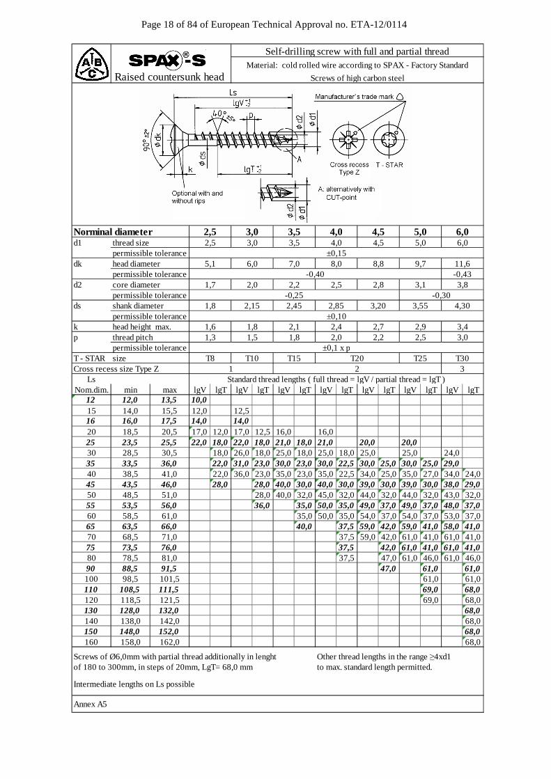
Raised countersunk head
Norminal diameterd1 thread size 2,5 3,0 3,5 4,0 4,5 5,0 6,0 permissible tolerancedk head diameter 5,1 6,0 7,0 8,0 8,8 9,7 11,6 permissible tolerance -0,43d2 core diameter 1,7 2,0 2,2 2,5 2,8 3,1 3,8
permissible tolerance -0,25 -0,30ds shank diameter 1,8 2,15 2,45 2,85 3,20 3,55 4,30
permissible tolerancek head height max. 1,6 1,8 2,1 2,4 2,7 2,9 3,4p thread pitch 1,3 1,5 1,8 2,0 2,2 2,5 3,0 permissible toleranceT - STAR size T8 T10 T15 T20 T25 T30Cross recess size Type Z 1 2 3
LsNom.dim. min max lgV lgT lgV lgT lgV lgT lgV lgT lgV lgT lgV lgT lgV lgT
12 12,0 13,5 10,015 14,0 15,5 12,0 12,516 16,0 17,5 14,0 14,020 18,5 20,5 17,0 12,0 17,0 12,5 16,0 16,025 23,5 25,5 22,0 18,0 22,0 18,0 21,0 18,0 21,0 20,0 20,030 28,5 30,5 18,0 26,0 18,0 25,0 18,0 25,0 18,0 25,0 25,0 24,035 33,5 36,0 22,0 31,0 23,0 30,0 23,0 30,0 22,5 30,0 25,0 30,0 25,0 29,040 38,5 41,0 22,0 36,0 23,0 35,0 23,0 35,0 22,5 34,0 25,0 35,0 27,0 34,0 24,045 43,5 46,0 28,0 28,0 40,0 30,0 40,0 30,0 39,0 30,0 39,0 30,0 38,0 29,050 48,5 51,0 28,0 40,0 32,0 45,0 32,0 44,0 32,0 44,0 32,0 43,0 32,055 53,5 56,0 36,0 35,0 50,0 35,0 49,0 37,0 49,0 37,0 48,0 37,060 58,5 61,0 35,0 50,0 35,0 54,0 37,0 54,0 37,0 53,0 37,065 63,5 66,0 40,0 37,5 59,0 42,0 59,0 41,0 58,0 41,070 68,5 71,0 37,5 59,0 42,0 61,0 41,0 61,0 41,075 73,5 76,0 37,5 42,0 61,0 41,0 61,0 41,080 78,5 81,0 37,5 47,0 61,0 46,0 61,0 46,090 88,5 91,5 47,0 61,0 61,0100 98,5 101,5 61,0 61,0110 108,5 111,5 69,0 68,0120 118,5 121,5 69,0 68,0130 128,0 132,0 68,0140 138,0 142,0 68,0150 148,0 152,0 68,0160 158,0 162,0 68,0
Screws of Ø6,0mm with partial thread additionally in lenght Other thread lengths in the range ≥4xd1of 180 to 300mm, in steps of 20mm, LgT= 68,0 mm to max. standard length permitted.
Intermediate lengths on Ls possible
Annex A5
±0,15
±0,10
2,5 5,0 6,0
Standard thread lengths ( full thread = lgV / partial thread = lgT )
3,0 3,5 4,0
Self-drilling screw with full and partial threadMaterial: cold rolled wire according to SPAX - Factory Standard
Screws of high carbon steel
±0,1 x p
4,5
-0,40
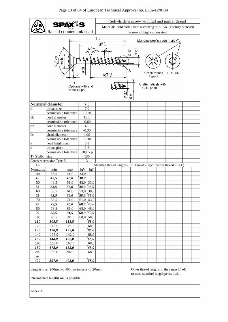
Page 19 of 84 of European Technical Approval no. ETA-12/0114
d1 thread size permissible tolerancedk head diameter permissible toleranced2 core diameter
permissible toleranceds shank diameter
permissible tolerancek head height max.max.p thread pitch permissible toleranceT - STAR sizeCross recess size Type Z
LsNom.dim. min max lgV lgT
40 38,5 41,0 33,045 43,5 46,0 38,050 48,5 51,0 43,0 33,055 53,5 56,0 48,0 33,060 58,5 61,0 53,0 38,065 63,5 66,0 58,0 38,070 68,5 71,0 61,0 43,075 73,5 76,0 68,0 43,080 78,5 81,0 68,0 48,090 88,5 91,5 68,0 53,0100 98,5 101,5 68,0 58,0110 108,5 111,5 68,0120 118,5 121,5 68,0130 128,0 132,0 68,0140 138,0 142,0 68,0150 148,0 152,0 68,0160 158,0 162,0 68,0180 178,0 182,0 68,0200 198,0 202,0 68,0to
400 397,0 402,0 68,0
Lenghts over 200mm to 400mm in steps of 20mm Other thread lengths in the range ≥4xd1to max. standard length permitted.
Intermediate lengths on Ls possible
Annex A6
7,0
13,1
4,5
±0,20
-0,60
-0,30
±0,104,90
Standard thread lengths ( full thread = lgV / partial thread = lgT )
Self-drilling screw with full and partial threadMaterial: cold rolled wire according to SPAX - Factory Standard
Screws of high carbon steelRaised countersunk head
Norminal diameter 7,0
3,83,5
±0,1 x pT303
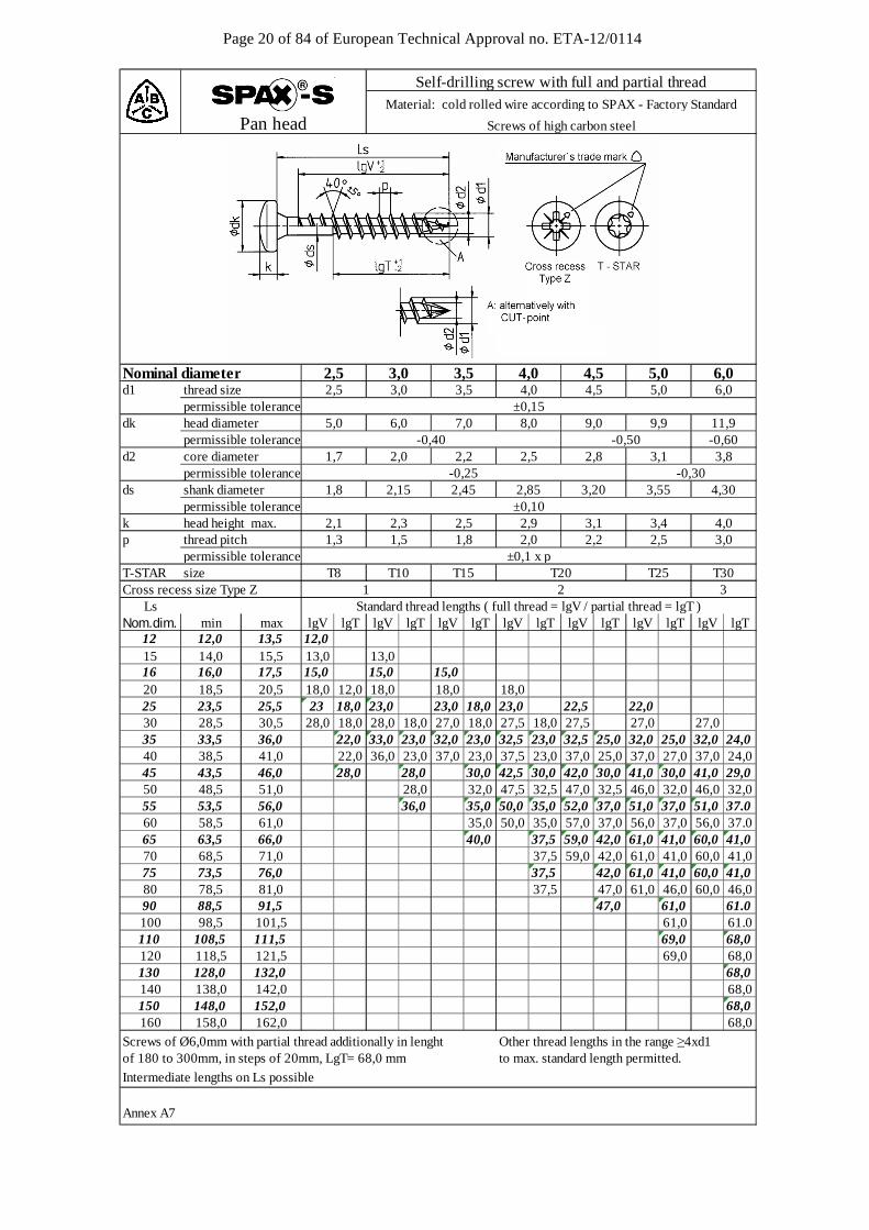
Page 20 of 84 of European Technical Approval no. ETA-12/0114
Nominal diameterd1 thread size 2,5 3,0 3,5 4,0 4,5 5,0 6,0 permissible tolerancedk head diameter 5,0 6,0 7,0 8,0 9,0 9,9 11,9 permissible tolerance -0,40 -0,50 -0,60d2 core diameter 1,7 2,0 2,2 2,5 2,8 3,1 3,8
permissible tolerance -0,25 -0,30ds shank diameter 1,8 2,15 2,45 2,85 3,20 3,55 4,30
permissible tolerancek head height max. 2,1 2,3 2,5 2,9 3,1 3,4 4,0p thread pitch 1,3 1,5 1,8 2,0 2,2 2,5 3,0 permissible toleranceT-STAR size T8 T10 T15 T20 T25 T30Cross recess size Type Z 1 2 3
LsNom.dim. min max lgV lgT lgV lgT lgV lgT lgV lgT lgV lgT lgV lgT lgV lgT
12 12,0 13,5 12,015 14,0 15,5 13,0 13,016 16,0 17,5 15,0 15,0 15,020 18,5 20,5 18,0 12,0 18,0 18,0 18,025 23,5 25,5 23 18,0 23,0 23,0 18,0 23,0 22,5 22,030 28,5 30,5 28,0 18,0 28,0 18,0 27,0 18,0 27,5 18,0 27,5 27,0 27,035 33,5 36,0 22,0 33,0 23,0 32,0 23,0 32,5 23,0 32,5 25,0 32,0 25,0 32,0 24,040 38,5 41,0 22,0 36,0 23,0 37,0 23,0 37,5 23,0 37,0 25,0 37,0 27,0 37,0 24,045 43,5 46,0 28,0 28,0 30,0 42,5 30,0 42,0 30,0 41,0 30,0 41,0 29,050 48,5 51,0 28,0 32,0 47,5 32,5 47,0 32,5 46,0 32,0 46,0 32,055 53,5 56,0 36,0 35,0 50,0 35,0 52,0 37,0 51,0 37,0 51,0 37.060 58,5 61,0 35,0 50,0 35,0 57,0 37,0 56,0 37,0 56,0 37.065 63,5 66,0 40,0 37,5 59,0 42,0 61,0 41,0 60,0 41,070 68,5 71,0 37,5 59,0 42,0 61,0 41,0 60,0 41,075 73,5 76,0 37,5 42,0 61,0 41,0 60,0 41,080 78,5 81,0 37,5 47,0 61,0 46,0 60,0 46,090 88,5 91,5 47,0 61,0 61.0100 98,5 101,5 61,0 61.0110 108,5 111,5 69,0 68,0120 118,5 121,5 69,0 68,0130 128,0 132,0 68,0140 138,0 142,0 68,0150 148,0 152,0 68,0160 158,0 162,0 68,0
Screws of Ø6,0mm with partial thread additionally in lenght Other thread lengths in the range ≥4xd1of 180 to 300mm, in steps of 20mm, LgT= 68,0 mm to max. standard length permitted.
Intermediate lengths on Ls possible
Annex A7
Pan head
Self-drilling screw with full and partial threadMaterial: cold rolled wire according to SPAX - Factory Standard
Screws of high carbon steel
2,5 4,5 5,0 6,03,0 3,5 4,0
±0,15
±0,10
±0,1 x p
Standard thread lengths ( full thread = lgV / partial thread = lgT )
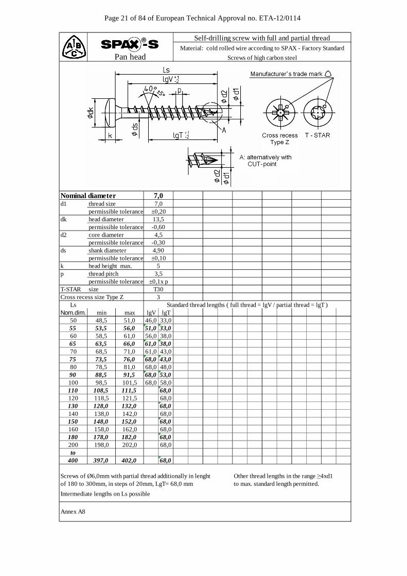
Page 21 of 84 of European Technical Approval no. ETA-12/0114
d1 thread size permissible tolerancedk head diameter permissible toleranced2 core diameter
permissible toleranceds shank diameter
permissible tolerancek head height max.p thread pitch permissible toleranceT-STAR sizeCross recess size Type Z
LsNom.dim. min max lgV lgT
50 48,5 51,0 46,0 33,055 53,5 56,0 51,0 33,060 58,5 61,0 56,0 38,065 63,5 66,0 61,0 38,070 68,5 71,0 61,0 43,075 73,5 76,0 68,0 43,080 78,5 81,0 68,0 48,090 88,5 91,5 68,0 53,0100 98,5 101,5 68,0 58,0110 108,5 111,5 68,0120 118,5 121,5 68,0130 128,0 132,0 68,0140 138,0 142,0 68,0150 148,0 152,0 68,0160 158,0 162,0 68,0180 178,0 182,0 68,0200 198,0 202,0 68,0to
400 397,0 402,0 68,0
Screws of Ø6,0mm with partial thread additionally in lenght Other thread lengths in the range ≥4xd1of 180 to 300mm, in steps of 20mm, LgT= 68,0 mm to max. standard length permitted.
Intermediate lengths on Ls possible
Annex A8
T303
4,90±0,10
Standard thread lengths ( full thread = lgV / partial thread = lgT )
7,0
-0,30
7,0
13,5
5
4,5
3,5±0,1x p
±0,20
-0,60
Self-drilling screw with full and partial threadMaterial: cold rolled wire according to SPAX - Factory Standard
Screws of high carbon steelPan head
Nominal diameter
Page 22 of 84 of European Technical Approval no. ETA-12/0114
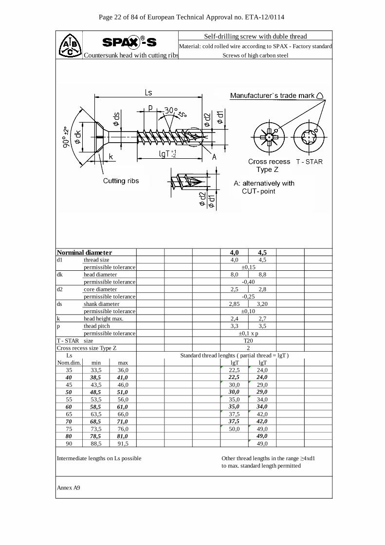
Countersunk head with cutting ribs
d1 thread size 4,0 4,5 permissible tolerancedk head diameter 8,0 8,8 permissible toleranced2 core diameter 2,5 2,8
permissible toleranceds shank diameter 2,85 3,20
permissible tolerancek head height max. 2,4 2,7p thead pitch 3,3 3,5 permissible toleranceT - STAR size T20 Cross recess size Type Z 2
LsNom.dim. min max lgT lgT
35 33,5 36,040 38,5 41,045 43,5 46,050 48,5 51,055 53,5 56,060 58,5 61,065 63,5 66,070 68,5 71,075 73,5 76,080 78,5 81,090 88,5 91,5
Intermediate lengths on Ls possible Other thread lengths in the range ≥4xd1to max. standard length permitted
Annex A9
4,5
±0,15
Self-drilling screw with duble threadMaterial: cold rolled wire according to SPAX - Factory standard
Screws of high carbon steel
Standard thread lenghts ( partial thread = lgT )
-0,40
-0,25
±0,10
±0,1 x p
35,037,5
50,037,5
Norminal diameter 4,0
24,0
29,0
34,0
42,0
22,522,530,030,035,0
49,0
49,0
24,0
29,0
34,0
42,0
49,0

Page 23 of 84 of European Technical Approval no. ETA-12/0114
d1 thread size 4,0 4,5 5,0 6,0 permissible tolerancedk head diameter 8,0 8,8 9,7 11,6 permissible tolerancedb hole diameter 2,50
permissible toleranced2 core diameter 2,5 2,8 3,1 3,8
permissible toleranceds1 shank diameter 2,85 3,20 3,55 4,30
permissible toleranceds2 shank diameter 3,60 3,80 4,50 ohne
permissible tolerancek head height max. 2,4 2,7 2,9 3,4p thread pitch 2,0 2,2 2,5 3,0 permissible toleranceCross recess size Z
LsNom.dim. min max lgV lgV lgV lgV
25 23,5 26,030 28,5 31,035 33,5 36,040 38,5 41,045 43,5 46,050 48,5 51,055 53,5 56,060 58,5 61,065 63,5 66,070 68,5 71,075 73,5 76,080 78,5 81,090 88,5 91,5
100 98,5 101,5110 108,5 111,5120 118,5 121,5130 128,0 132,0140 138,0 142,0150 148,0 152,0160 158,0 162,0
Screw of Ø 6,0 mm with partial thread additionally in lengthsof 180 to 300 mm , in steps of 20mm, lgV = 68,0 mm
Intermediate lengths on Ls possible
Annex A10
Self-drilling screw with full threadMaterial: cold rolled wire according to SPAX - Factory Standard
Screws of high carbon steel
18,0
5,0 6,0
Standard thread lengths ( full thread = lgV )3
Countersunk with head hole
23,0
Nominal diameter 4,0 4,5
20,0
to max. standard length permittedOther thead lengths in the range ≥4xd1
54,050,0
59,0
59,0 61,059,0 61,0
69,0
27,532,5 30,030,0
25,0
46,0
56,049,054,0
59,0
39,039,0
49,0
61,0
68,068,068,0
61,0
61,0
68,0
37,5
47,5
34,0
44,042,5
68,0
61,0
61,0
35,0
44,0
69,0
41,0
51,0
61,0
61,0
61,0
68,0
± 0,15
-0,50
± 0,15
-0,25 -0,30
± 0,10
±0,10
± 0,1 x p2

Page 24 of 84 of European Technical Approval no. ETA-12/0114
Nominal diameterd1 thread size 3,0 3,5 4,0 4,5 5,1 6,1 permissible tolerancedk head diameter 6,0 7,0 8,0 8,8 9,7 11,6 permissible tolerance -0,43d2 core diameter 2,1 2,4 2,8 3,0 3,4 3,8
permissible tolerance -0,30ds shank diameter 2,25 2,60 3,00 3,30 4,30
permissible tolerancek head height max. 1,8 2,1 2,4 2,7 2,9 3,4p thread pitch 1,5 1,8 2,0 2,2 2,5 3,0 permissible toleranceT-STAR size T10 T15 T20 T25 T30Cross recess size Type Z
Ls Standard thread lengths ( full thread = lgV / partial thread = lgT )Nom.dim. min max lgV lgT lgV lgT lgV lgT lgV lgT lgV lgT lgV lgT lgV lgT
15 14,0 15,5 12,516 16,0 17,5 14,020 18,5 20,5 17,0 16,0 16,025 23,5 25,5 21,0 18,0 21,0 18,0 21,0 20,0 20,030 28,5 30,5 26,0 18,0 25,0 18,0 25,0 18,0 25,0 25,0 24,035 33,5 36,0 31,0 23,0 30,0 23,0 30,0 23,0 30,0 25,0 30,0 25,0 29,0 24,040 38,5 41,0 36,0 23,0 35,0 23,0 35,0 23,0 34,0 25,0 35,0 27,0 34,0 24,045 43,5 46,0 28,0 40,0 30,0 40,0 30,0 39,0 30,0 39,0 30,0 38,0 29,050 48,5 51,0 28,0 40,0 32,0 45,0 32,0 44,0 32,0 44,0 32,0 43,0 32,055 53,5 56,0 36,0 35,0 50,0 35,0 49,0 37,0 49,0 37,0 48,0 37,060 58,5 61,0 35,0 50,0 35,0 54,0 37,0 54,0 37,0 53,0 37,065 63,5 66,0 40,0 37,5 59,0 42,0 59,0 41,0 58,0 41,070 68,5 71,0 37,5 59,0 42,0 61,0 41,0 61,0 41,075 73,5 76,0 37,5 42,0 61,0 41,0 61,0 41,080 78,5 81,0 37,5 47,0 61,0 46,0 61,0 46,090 88,5 91,5 47,0 61,0 61,0100 98,5 101,5 61,0 61,0110 108,5 111,5 69,0 68,0120 118,5 121,5 69,0 68,0130 128,0 132,0 68,0140 138,0 142,0 68,0150 148,0 152,0 68,0160 158,0 162,0 68,0
Other thread lengths in the range ≥4xd1Intermediate lengths on Ls possible to max. standard length permitted.
Annex A11
3,0
-0,25
±0,1 x p
3,5
3,75
Flat countersunk head
4,5 5,0 6,0
±0,2 ±0,25
3
4,0
1
±0,10
2
-0,40
Self-drilling screw with full and partial threadMaterial: cold rolled wire according to SPAX - Factory Standard
Stainless steel screws
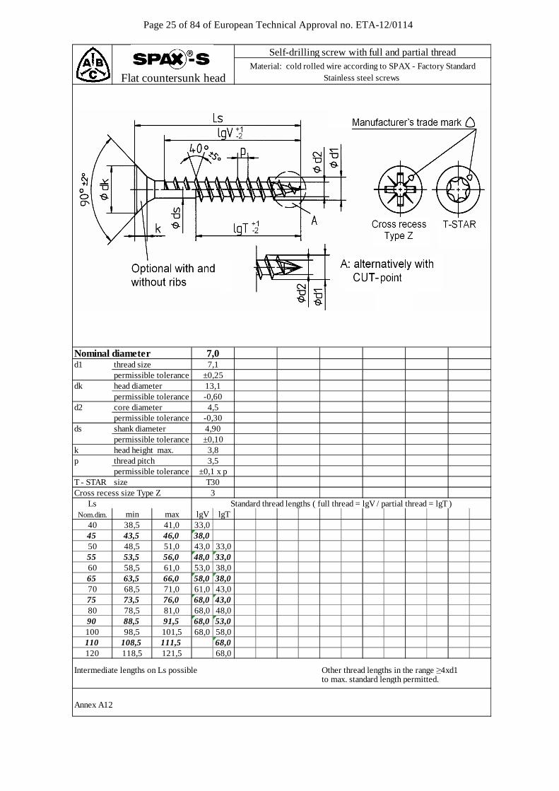
Page 25 of 84 of European Technical Approval no. ETA-12/0114
d1 thread size 7,1 permissible tolerance ±0,25dk head diameter 13,1 permissible tolerance -0,60d2 core diameter 4,5
permissible tolerance -0,30ds shank diameter 4,90
permissible tolerance ±0,10k head height max. 3,8p thread pitch 3,5 permissible tolerance ±0,1 x pT - STAR size T30Cross recess size Type Z 3
LsNom.dim. min max lgV lgT
40 38,5 41,0 33,045 43,5 46,0 38,050 48,5 51,0 43,0 33,055 53,5 56,0 48,0 33,060 58,5 61,0 53,0 38,065 63,5 66,0 58,0 38,070 68,5 71,0 61,0 43,075 73,5 76,0 68,0 43,080 78,5 81,0 68,0 48,090 88,5 91,5 68,0 53,0100 98,5 101,5 68,0 58,0110 108,5 111,5 68,0120 118,5 121,5 68,0
Intermediate lengths on Ls possible Other thread lengths in the range ≥4xd1 to max. standard length permitted.
Annex A12
Standard thread lengths ( full thread = lgV / partial thread = lgT )
Nominal diameter 7,0
Self-drilling screw with full and partial threadMaterial: cold rolled wire according to SPAX - Factory Standard
Stainless steel screws Flat countersunk head

Page 26 of 84 of European Technical Approval no. ETA-12/0114
3,0 3,5 4,0 4,5 5,0 6,0d1 thread size 3,0 3,5 4,0 4,5 5,1 6,1 permissible tolerancedk head diameter permissible tolerancedk1 contersink diameter
permissible toleranced2 core diameter
permissible toleranceds shank diameter
permissible tolerancek head height max.p thread pitch permissible toleranceT - STAR sizeCross recess size Type Z
LsNom.dim. min max lgV lgT lgV lgT lgV lgT lgV lgT lgV lgT lgV lgT
12 12,0 13,5 13,015 16,0 17,5 14,016 16,0 17,5 15,0 15,020 18,5 20,5 18,0 12,5 18,0 18,025 23,5 25,5 23,0 18,0 23,0 18,0 23,0 22,5 22,030 28,5 30,5 28,0 18,0 27,0 18,0 27,5 18,0 27,5 27,0 27,035 33,5 36,0 33,0 23,0 32,0 23,0 32,5 23,0 32,5 25,0 32,0 25,0 32,0 24,040 38,5 41,0 36,0 23,0 37,0 23,0 37,5 23,0 37,0 25,0 37,0 27,0 37,0 24,045 43,5 46,0 28,0 30,0 42,5 30,0 42,0 30,0 41,0 30,0 41,0 29,050 48,5 51,0 28,0 32,0 47,5 32,5 47,0 32,5 46,0 32,0 46,0 32,055 53,5 56,0 36,0 35,0 50,0 35,0 52,0 37,0 51,0 37,0 51,0 37,060 58,5 61,0 35,0 50,0 35,0 57,0 37,0 56,0 37,0 56,0 37,065 63,5 66,0 40,0 37,5 59,0 42,0 61,0 41,0 61,0 41,070 68,5 71,0 37,5 59,0 42,0 61,0 41,0 61,0 41,075 73,5 76,0 37,5 42,0 61,0 41,0 61,0 41,080 78,5 81,0 37,5 47,0 61,0 46,0 61,0 46,090 88,5 91,5 47,0 61,0 61,0
100 98,5 101,5 61,0 61,0110 108,5 111,5 69,0 68,0120 118,5 121,5 69,0 68,0130 128,5 131,5 68,0140 138,5 141,5 68,0150 148,5 151,5 68,0160 158,5 161,5 68,0
Intermediate lengths on Ls possible Other thread lengths in the range ≥4xd1to max. standard length permitted.
Annex A13
4,9
10,6 11,6-0,50 -0,60
9,6
5,0 5,4 5,94,9
2,1
2,25
1,51,5
±0,10
2,82,4
13,6-0,40
8,67,9
2,2 2,41,8
+0,206,9
3,0 3,4 3,8-0,25 -0,30
1,8 2,2 2,5
3,75 4,302,60 3,00 3,30
1,9 2,0
Standard thread lengths ( full thread = lgV / partial thread = lgT )
T25 T30
3,0±0,1 x p
2,0
T20T152
T10
±0,20 ±0,25
Self-drilling screw with full and partial threadMaterial: cold rolled wire according to SPAX - Factory Standard
Stainless steel screws Washer head
Nominal diameter

Page 27 of 84 of European Technical Approval no. ETA-12/0114
d1 thread size permissible tolerancedk head diameter permissible tolerancedk1 contersink diameter
permissible toleranced2 core diameter
permissible toleranceds shank diameter
permissible tolerancek head height max. p thread pitch permissible toleranceT - STAR size
LsNom.dim. min max lgV lgT
50 48,5 51,0 46,0 33,055 53,5 56,0 51,0 33,060 58,5 61,0 56,0 38,065 63,5 66,0 61,0 38,070 68,5 71,0 61,0 43,075 73,5 76,0 68,0 43,080 78,5 81,0 68,0 48,090 88,5 91,5 68,0 53,0100 98,5 101,5 68,0 58,0110 108,5 111,5 68,0120 118,5 121,5 68,0
Intermediate lengths on Ls possible Other thread lengths in the range ≥4xd1to max. standard length permitted.
Annex A14
Self-drilling screw with full and partial thread
Material: cold rolled wire according to SPAX - Factory Standard
Stainless steel screwWasher head
Norminal diameter 7,0
Standard thread lengths ( full thread = lgV / partial thread = lgT )
4,90
7,1
18,0
7,8
4,5
-0,60
±0,25
-0,30
T30±0,1 x p
±0,10
-0,30
3,73,5
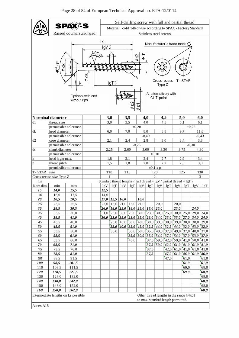
Page 28 of 84 of European Technical Approval no. ETA-12/0114
d1 thread size 3,0 3,5 4,0 4,5 5,1 6,1 permissible tolerancedk head diameter 6,0 7,0 8,0 8,8 9,7 11,6 permissible tolerance -0,43d2 core diameter 2,1 2,4 2,8 3,0 3,4 3,8
permissible tolerance -0,30ds shank diameter 2,25 2,60 3,75 4,30
permissible tolerancek head hight max. 1,8 2,1 2,4 2,7 2,9 3,4p thread pitch 1,5 1,8 2,0 2,2 2,5 3,0 permissible toleranceT - STAR size T10 T15 T20 T25 T30Cross recess size Type Z 1 2 3
LsNom.dim. min max lgV lgT lgV lgT lgV lgT lgV lgT lgV lgT lgV lgT
15 14,0 15,5 12,516 16,0 17,5 14,020 18,5 20,5 17,0 12,5 16,0 16,025 23,5 25,5 22,0 18,0 21,0 18,0 21,0 20,0 20,030 28,5 30,5 26,0 18,0 25,0 18,0 25,0 18,0 25,0 25,0 24,035 33,5 36,0 31,0 23,0 30,0 23,0 30,0 23,0 30,0 25,0 30,0 25,0 29,0 24,040 38,5 41,0 36,0 23,0 35,0 23,0 35,0 23,0 34,0 25,0 35,0 27,0 34,0 24,045 43,5 46,0 28,0 40,0 30,0 40,0 30,0 39,0 30,0 39,0 30,0 38,0 29,050 48,5 51,0 28,0 40,0 32,0 45,0 32,5 44,0 32,5 44,0 32,0 43,0 32,055 53,5 56,0 36,0 35,0 50,0 35,0 49,0 37,0 49,0 37,0 48,0 37,060 58,5 61,0 35,0 50,0 35,0 54,0 37,0 54,0 37,0 53,0 37,065 63,5 66,0 40,0 37,5 59,0 42,0 59,0 41,0 58,0 41,070 68,5 71,0 37,5 59,0 42,0 61,0 41,0 61,0 41,075 73,5 76,0 37,5 42,0 61,0 41,0 61,0 41,080 78,5 81,0 37,5 47,0 61,0 46,0 61,0 46,090 88,5 91,5 47,0 61,0 61,0
100 98,5 101,5 61,0 61,0110 108,5 111,5 69,0 68,0120 118,5 121,5 69,0 68,0130 128,0 132,0 68,0140 138,0 142,0 68,0150 148,0 152,0 68,0160 158,0 162,0 68,0
Intermediate lengths on Ls possible Other thread lengths in the range ≥4xd1to max. standard length permitted.
Annex A15
Standard thread lengths ( full thread = lgV / partial thread = lgT )
Norminal diameter 3,0 3,5 4,0 4,5 5,0
Raised countersunk head
Self-drilling screw with full and partial threadMaterial: cold rolled wire according to SPAX - Factory Standard
Stainless steel screws
-0,40
±0,10
±0,25
±0,1 x p
3,00 3,30-0,25
±0,20
6,0
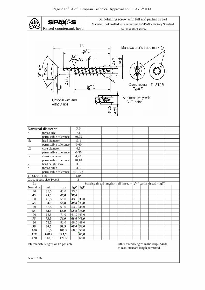
Page 29 of 84 of European Technical Approval no. ETA-12/0114
d1 thread size 7,1 permissible tolerance ±0,25dk head diameter 13,1 permissible tolerance -0,60d2 core diameter 4,5
permissible tolerance -0,30ds shank diameter 4,90
permissible tolerance ±0,10k head height max. 3,8p thread pitch 3,5 permissible tolerance ±0,1 x pT - STAR size T30Cross recess size Type Z 3
LsNom dim. min max lgV lgT
40 38,5 41,0 33,045 43,5 46,0 38,050 48,5 51,0 43,0 33,055 53,5 56,0 48,0 33,060 58,5 61,0 53,0 38,065 63,5 66,0 58,0 38,070 68,5 71,0 61,0 43,075 73,5 76,0 68,0 43,080 78,5 81,0 68,0 48,090 88,5 91,5 68,0 53,0100 98,5 101,5 68,0 58,0110 108,5 111,5 68,0120 118,5 121,5 68,0
Intermediate lengths on Ls possible Other thread lengths in the range ≥4xd1to max. standard length permitted.
Annex A16
Standard thread lengths ( full thread = lgV / partial thread = lgT )
Raised countersunk head
Self-drilling screw with full and partial threadMaterial: cold rolled wire according to SPAX - Factory Standard
Stailness steel screw
Norminal diameter 7,0
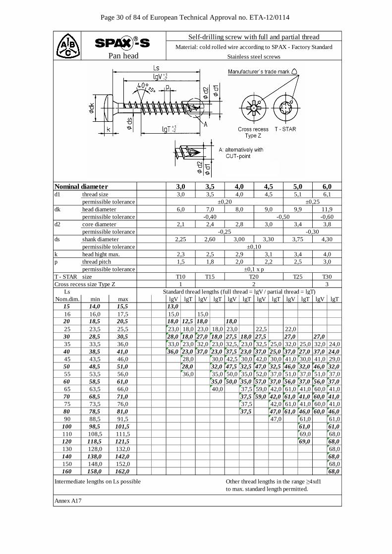
Page 30 of 84 of European Technical Approval no. ETA-12/0114
d1 thread size 3,0 3,5 4,0 4,5 5,1 6,1 permissible tolerancedk head diameter 6,0 7,0 8,0 9,0 9,9 11,9 permissible tolerance -0,50 -0,60d2 core diameter 2,1 2,4 2,8 3,0 3,4 3,8
permissible tolerance -0,30ds shank diameter 2,25 2,60 3,00 3,30 3,75 4,30
permissible tolerancek head hight max. 2,3 2,5 2,9 3,1 3,4 4,0p thread pitch 1,5 1,8 2,0 2,2 2,5 3,0 permissible toleranceT - STAR size T10 T15 T20 T25 T30Cross recess size Type Z 1 2 3
LsNom.dim. min max lgV lgT lgV lgT lgV lgT lgV lgT lgV lgT lgV lgT
15 14,0 15,5 13,016 16,0 17,5 15,0 15,020 18,5 20,5 18,0 12,5 18,0 18,025 23,5 25,5 23,0 18,0 23,0 18,0 23,0 22,5 22,030 28,5 30,5 28,0 18,0 27,0 18,0 27,5 18,0 27,5 27,0 27,035 33,5 36,0 33,0 23,0 32,0 23,0 32,5, 23,0 32,5 25,0 32,0 25,032,0 24,040 38,5 41,0 36,0 23,0 37,0 23,0 37,5 23,0 37,0 25,0 37,0 27,0 37,0 24,045 43,5 46,0 28,0 30,0 42,5 30,0 42,0 30,0 41,0 30,0 41,0 29,050 48,5 51,0 28,0 32,0 47,5 32,5 47,0 32,5 46,0 32,0 46,0 32,055 53,5 56,0 36,0 35,0 50,0 35,0 52,0 37,0 51,0 37,0 51,0 37,060 58,5 61,0 35,0 50,0 35,0 57,0 37,0 56,0 37,0 56,0 37,065 63,5 66,0 40,0 37,5 59,0 42,0 61,0 41,0 60,0 41,070 68,5 71,0 37,5 59,0 42,0 61,0 41,0 60,0 41,075 73,5 76,0 37,5 42,0 61,0 41,0 60,0 41,080 78,5 81,0 37,5 47,0 61,0 46,0 60,0 46,090 88,5 91,5 47,0 61,0 61,0
100 98,5 101,5 61,0 61,0110 108,5 111,5 69,0 68,0120 118,5 121,5 69,0 68,0130 128,0 132,0 68,0140 138,0 142,0 68,0150 148,0 152,0 68,0160 158,0 162,0 68,0
Intermediate lengths on Ls possible Other thread lengths in the range ≥4xd1to max. standard length permitted.
Annex A17
Standard thread lengths (full thread = lgV / partial thread = lgT)
3,0 3,5 4,0 4,5
±0,1 x p
±0,10
-0,25
-0,40
±0,20 ±0,25
Nominal diameter
Self-drilling screw with full and partial threadMaterial: cold rolled wire according to SPAX - Factory Standard
5,0 6,0
Stainless steel screwsPan head
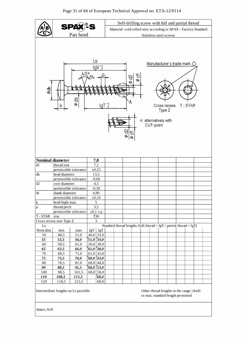
Page 31 of 84 of European Technical Approval no. ETA-12/0114
d1 thread size 7,1 permissible tolerance ±0,25dk head diameter 13,5 permissible tolerance -0,60d2 core diameter 4,5
permissible tolerance -0,30ds shank diameter 4,90
permissible tolerance ±0,10k head hight max. 5p thread pitch 3,5 permissible tolerance ±0,1 x pT - STAR size T30Cross recess size Type Z 3
LsNom.dim. min max lgV lgT
50 48,5 51,0 46,0 33,055 53,5 56,0 51,0 33,060 58,5 61,0 56,0 38,065 63,5 66,0 61,0 38,070 68,5 71,0 61,0 43,075 73,5 76,0 68,0 43,080 78,5 81,0 68,0 48,090 88,5 91,5 68,0 53,0100 98,5 101,5 68,0 58,0110 108,5 111,5 68,0120 118,5 121,5 68,0
Other thread lengths in the range ≥4xd1to max. standard length permitted.
Annex A18
Standard thread lengths (full thread = lgV / partial thread = lgT)
Intermediate lengths on Ls possible
Pan headMaterial: cold rolled wire according to SPAX - Factory Standard
Self-drilling screw with full and partial thread
Stainless steel screws
Nominal diameter 7,0
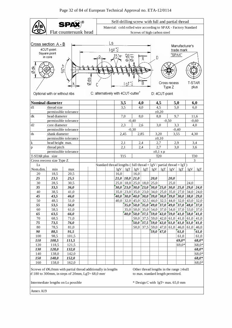
Page 32 of 84 of European Technical Approval no. ETA-12/0114
d1 thread size permissible tolerancedk head diameter permissible toleranced2 core diameter
permissible toleranceds shank diameter 2,45 2,85 3,20 3,55 4,30
permissible tolerancek head height max. 2,1 2,4 2,7 2,9 3,4p thread pitch permissible toleranceT-STAR plus size T15 T30Cross reecess size Type Z 2 3
LsNom.dim. min max lgV lgT lgV lgT lgV lgT lgV lgT lgV lgT
20 18,5 20,5 16,0 16,025 23,5 25,5 21,0 18,0 21,0 20,0 20,030 28,5 30,5 25,0 18,0 25,0 18,0 25,0 25,0 24,035 33,5 36,0 30,0 23,0 30,0 23,0 30,0 25,0 30,0 25,0 29,0 24,040 38,5 41,0 35,0 23,0 35,0 23,0 34,0 25,0 35,0 27,0 34,0 24,045 43,5 46,0 40,0 30,0 40,0 30,0 39,0 30,0 39,0 30,0 38,0 29,050 48,5 51,0 40,0 32,0 45,0 32,5 44,0 32,5 44,0 32,0 43,0 32,055 53,5 56,0 35,0 50,0 35,0 49,0 37,0 49,0 37,0 48,0 37,060 58,5 61,0 35,0 50,0 35,0 54,0 37,0 54,0 37,0 53,0 37,065 63,5 66,0 40,0 50,0 37,5 59,0 42,0 59,0 41,0 58,0 41,070 68,5 71,0 50,0 37,5 59,0 42,0 61,0 41,0 61,0 41,075 73,5 76,0 50,0 37,5 59,0 42,0 61,0 41,0 61,0 41,080 78,5 81,0 50,0 37,5 59,0 47,0 61,0 46,0 61,0 46,090 88,5 91,5 59,0 47,0 61,0 61,0100 98,5 101,5 61,0 61,0110 108,5 111,5 69,0* 68,0*120 118,5 121,5 69,0* 68,0*130 128,0 132,0 68,0*140 138,0 142,0 68,0*150 148,0 152,0 68,0*160 158,0 162,0 68,0*
Screws of Ø6,0mm with partial thread additionally in lengths Other thread lengths in the range ≥4xd1to max. standard length permitted.
Intermediate lengths on Ls possible * Design C with lgT= max. 65,0 mm
Annex A19
of 180 to 300mm, in steps of 20mm, LgT= 68,0 mm*
11,6
3,0 3,3-0,60
8,0 8,8 9,7
-0,30
2,1
Self-drilling screw with full and partial threadMaterial: cold rolled wire according to SPAX - Factory Standard
Screws of high carbon steelFlat countersunk head
3,6
4,0
±0,10
2,3
±0,1 x p
Standard thread lengths ( full thread = lgV / partial thread = lgT )
6,0Nominal diameter6,03,5 4,54,0
T20
5,0
2,6-0,40
2,7
-0,40
2,4 3,0
±0,207,0
-0,50
3,5 4,05,0
4,5

Page 33 of 84 of European Technical Approval no. ETA-12/0114
d1 thread size permissible tolerancedk head diameter permissible tolerancedk1 countersink diameter
permissible toleranced2 core diameter
permissible toleranceds shank diameter 2,45
permissible tolerancek head height max.p thread pitch permissible toleranceT-STAR plus sizeCross recess size Type Z
LsNom.dim. min max lgV lgT lgV lgT lgV lgT lgV lgT lgV lgT
16 16,0 17,5 15,020 18,5 20,5 18,0 18,025 23,5 25,5 23,0 18,0 23,0 22,5 22,030 28,5 30,5 27,0 18,0 27,5 18,0 27,5 27,0 27,035 33,5 36,0 32,0 23,0 32,5 23,0 32,5 25,0 32,0 25,0 32,0 24,040 38,5 41,0 37,0 23,0 37,5 23,0 37,0 25,0 37,0 27,0 37,0 24,045 43,5 46,0 40,0 30,0 42,5 30,0 42,0 30,0 41,0 30,0 41,0 29,050 48,5 51,0 40,0 32,0 47,5 32,5 47,0 32,5 46,0 32,0 46,0 32,055 53,5 56,0 35,0 50,0 35,0 52,0 37,0 51,0 37,0 51,0 37,060 58,5 61,0 35,0 50,0 35,0 57,0 37,0 56,0 37,0 56,0 37,065 63,5 66,0 40,0 50,0 37,5 59,0 42,0 61,0 41,0 61,0 41,070 68,5 71,0 50,0 37,5 59,0 42,0 61,0 41,0 61,0 41,075 73,5 76,0 50,0 37,5 59,0 42,0 61,0 41,0 61,0 41,080 78,5 81,0 59,0 47,0 61,0 46,0 61,0 46,090 88,5 91,5 59,0 47,0 61,0 61,0100 98,5 101,5 61,0 61,0110 108,5 111,5 69,0* 68,0*120 118,5 121,5 69,0* 68,0*130 128,0 132,0 68,0*140 138,0 142,0 68,0*150 148,0 152,0 68,0*160 158,0 162,0 68,0*
Screws of Ø6,0mm with partial thread additionally in lengths Other thread lengths in the range ≥4xd1to max. standard length permitted.
Intermediate lengths on Ls possible * Design C with lgT= max. 65,0 mm
Annex A20
of 180 to 300mm, in steps of 20mm, LgT= 68,0 mm*
2,6
T30
-0,50 -0,60
2,23,62,42,1 2,7
4,302,85
3,1
2
2,01,8 1,93,0
3,55
T20
-0,30 -0,40
3,5
3,20
3,3 4,0
6,0
13,6
6,94,9 5,9
4,0 4,5 5,0
11,6±0,2010,68,6 9,6
Nominal diameter
T15
±0,10
±0,1 x p
3,5
2,3 3,0
5,0 5,4+0,20
Standard thread lengths ( full thread = lgV / partial thread = lgT )
Self-drilling screw with full and partial threadMaterial: cold rolled wire according to SPAX - Factory Standard
Screws of high carbon steelWasher head
6,04,0 4,5 5,0

Page 34 of 84 of European Technical Approval no. ETA-12/0114
d1 thread size permissible tolerancedk head diameter permissible toleranced2 core diameter
permissible toleranceds shank diameter 2,45 2,85 3,20 3,55 4,30
permissible tolerancek head height max. 2,1 2,4 2,7 2,9 3,4p thread pitch permissible toleranceT-STAR plus size T15 T30Cross recess size Type Z 2 3
LsNom.dim. min max lgV lgT lgV lgT lgV lgT lgV lgT lgV lgT
20 18,5 20,5 16,0 16,025 23,5 25,5 23,0 18,0 21,0 20,0 20,030 28,5 30,5 25,0 18,0 25,0 18,0 25,0 25,0 24,035 33,5 36,0 30,0 23,0 30,0 23,0 30,0 25,0 30,0 25,0 29,040 38,5 41,0 35,0 23,0 35,0 23,0 34,0 25,0 35,0 27,0 34,0 24,045 43,5 46,0 40,0 30,0 40,0 30,0 39,0 30,0 39,0 30,0 38,0 29,050 48,5 51,0 40,0 32,0 45,0 32,5 44,0 32,5 44,0 32,0 43,0 32,055 53,5 56,0 35,0 50,0 35,0 49,0 37,0 49,0 37,0 48,0 37,060 58,5 61,0 35,0 50,0 35,0 54,0 37,0 54,0 37,0 53,0 37,065 63,5 66,0 40,0 50,0 37,5 59,0 42,0 59,0 41,0 58,0 41,070 68,5 71,0 50,0 37,5 59,0 42,0 61,0 41,0 61,0 41,075 73,5 76,0 50,0 37,5 59,0 42,0 61,0 41,0 61,0 41,080 78,5 81,0 50,0 37,5 59,0 47,0 61,0 46,0 61,0 46,090 88,5 91,5 59,0 47,0 61,0 61,0100 98,5 101,5 61,0 61,0110 108,5 111,5 69,0* 68,0*120 118,5 121,5 69,0* 68,0*130 128,0 132,0 68,0*140 138,0 142,0 68,0*150 148,0 152,0 68,0*160 158,0 162,0 68,0*
Screws of Ø6,0mm with partial thread additionally in lengths Other thread lengths in the range ≥4xd1to max. standard length permitted.
Intermediate lengths on Ls possible * Design C with lgT= max. 65,0 mm
Annex A21
of 180 to 300mm, in steps of 20mm, LgT= 68,0 mm*
Material: cold rolled wire according to SPAX - Factory Standard
Screws of high carbon steel
Nominal diamerer
Raised countersunk head
2,1
Standard thread lengths ( full thread = lgV / partial thread = lgT )
3,5 4,0 4,55,05,0 6,0
Self-drilling screw with full and partial thread
3,6
6,0±0,20
7,0
4,02,3 3,32,6
8,0 8,8-0,40
4,0
-0,50
4,5
9,7 11,6
3,5
T20±0,1 x p
3,0
±0,10
-0,30 -0,40
2,4 2,7 3,0
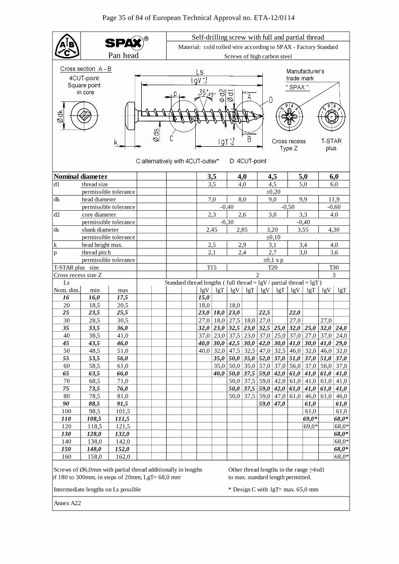
Page 35 of 84 of European Technical Approval no. ETA-12/0114
d1 thread size permissible tolerancedk head diameter permissible toleranced2 core diameter
permissible toleranceds shank diameter 2,45 2,85 3,20 3,55 4,30
permissible tolerancek head height max.p thread pitch permissible toleranceT-STAR plus size T15 T30Cross recess size Z 2 3
LsNom. dim. min max lgV lgT lgV lgT lgV lgT lgV lgT lgV lgT
16 16,0 17,5 15,020 18,5 20,5 18,0 18,025 23,5 25,5 23,0 18,0 23,0 22,5 22,030 28,5 30,5 27,0 18,0 27,5 18,0 27,0 27,0 27,035 33,5 36,0 32,0 23,0 32,5 23,0 32,5 25,0 32,0 25,0 32,0 24,040 38,5 41,0 37,0 23,0 37,5 23,0 37,0 25,0 37,0 27,0 37,0 24,045 43,5 46,0 40,0 30,0 42,5 30,0 42,0 30,0 41,0 30,0 41,0 29,050 48,5 51,0 40,0 32,0 47,5 32,5 47,0 32,5 46,0 32,0 46,0 32,055 53,5 56,0 35,0 50,0 35,0 52,0 37,0 51,0 37,0 51,0 37,060 58,5 61,0 35,0 50,0 35,0 57,0 37,0 56,0 37,0 56,0 37,065 63,5 66,0 40,0 50,0 37,5 59,0 42,0 61,0 41,0 61,0 41,070 68,5 71,0 50,0 37,5 59,0 42,0 61,0 41,0 61,0 41,075 73,5 76,0 50,0 37,5 59,0 42,0 61,0 41,0 61,0 41,080 78,5 81,0 50,0 37,5 59,0 47,0 61,0 46,0 61,0 46,090 88,5 91,5 59,0 47,0 61,0 61,0100 98,5 101,5 61,0 61,0110 108,5 111,5 69,0* 68,0*120 118,5 121,5 69,0* 68,0*130 128,0 132,0 68,0*140 138,0 142,0 68,0*150 148,0 152,0 68,0*160 158,0 162,0 68,0*
Screws of Ø6,0mm with partial thread additionally in lengths Other thread lengths in the range ≥4xd1to max. standard length permitted.
Intermediate lengths on Ls possible * Design C with lgT= max. 65,0 mm
Annex A22
2,3 3,3-0,40 -0,50
2,6 3,0
9,9 11,9
T20
4,0
2,7
-0,30 -0,40
-0,607,0
±0,10
6,03,5 4,54,03,5
5,0
8,0 9,0±0,20
3,4 4,0
Standard thread lengths ( full thread = lgV / partial thread = lgT )
2,53,0 3,6
2,9 3,1
±0,1 x p2,1 2,4
of 180 to 300mm, in steps of 20mm, LgT= 68,0 mm*
Self-drilling screw with full and partial threadMaterial: cold rolled wire according to SPAX - Factory Standard
Screws of high carbon steel
4,0 4,5
Pan head
5,0 6,0Nominal diameter
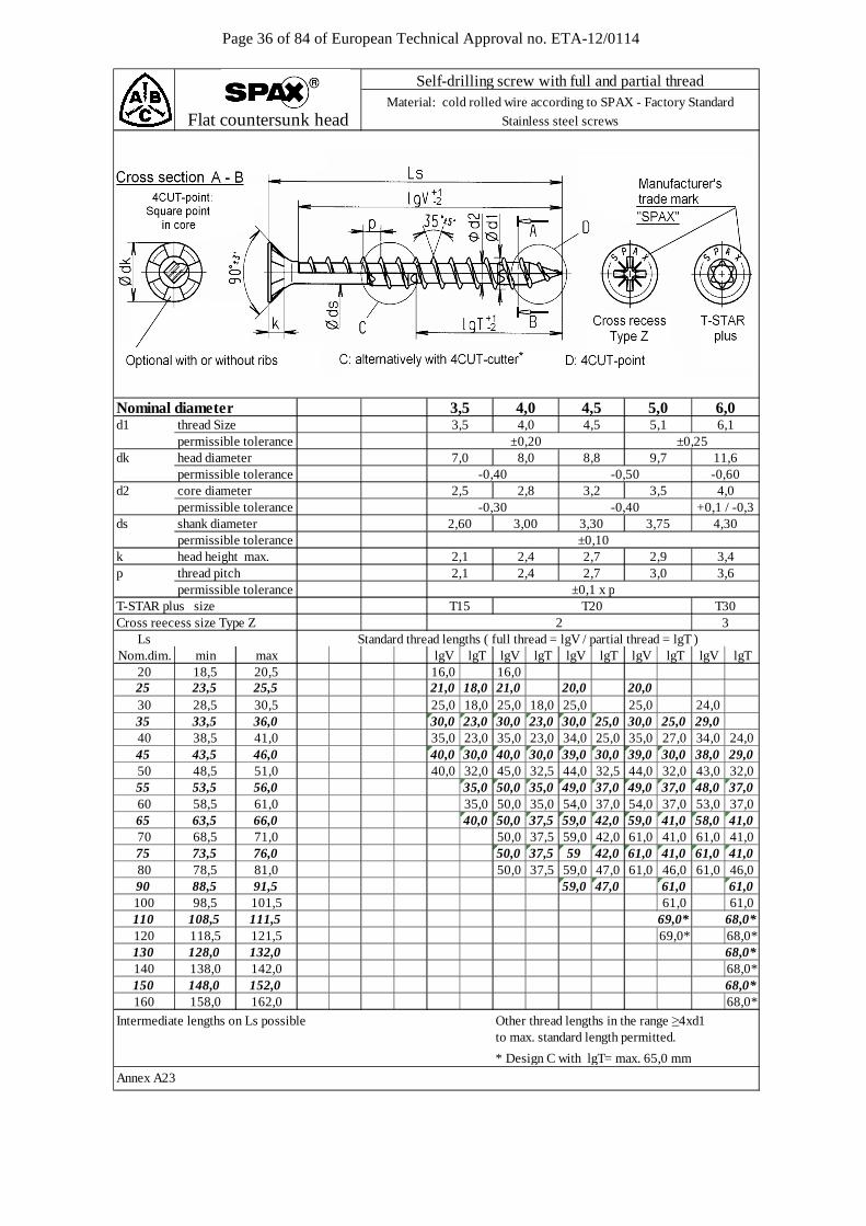
Page 36 of 84 of European Technical Approval no. ETA-12/0114
d1 thread Size permissible tolerancedk head diameter permissible toleranced2 core diameter
permissible toleranceds shank diameter 2,60 3,00 3,30 3,75 4,30
permissible tolerancek head height max. 2,1 2,4 2,7 2,9 3,4p thread pitch permissible toleranceT-STAR plus size T15 T30Cross reecess size Type Z 2 3
LsNom.dim. min max lgV lgT lgV lgT lgV lgT lgV lgT lgV lgT
20 18,5 20,5 16,0 16,025 23,5 25,5 21,0 18,0 21,0 20,0 20,030 28,5 30,5 25,0 18,0 25,0 18,0 25,0 25,0 24,035 33,5 36,0 30,0 23,0 30,0 23,0 30,0 25,0 30,0 25,0 29,040 38,5 41,0 35,0 23,0 35,0 23,0 34,0 25,0 35,0 27,0 34,0 24,045 43,5 46,0 40,0 30,0 40,0 30,0 39,0 30,0 39,0 30,0 38,0 29,050 48,5 51,0 40,0 32,0 45,0 32,5 44,0 32,5 44,0 32,0 43,0 32,055 53,5 56,0 35,0 50,0 35,0 49,0 37,0 49,0 37,0 48,0 37,060 58,5 61,0 35,0 50,0 35,0 54,0 37,0 54,0 37,0 53,0 37,065 63,5 66,0 40,0 50,0 37,5 59,0 42,0 59,0 41,0 58,0 41,070 68,5 71,0 50,0 37,5 59,0 42,0 61,0 41,0 61,0 41,075 73,5 76,0 50,0 37,5 59 42,0 61,0 41,0 61,0 41,080 78,5 81,0 50,0 37,5 59,0 47,0 61,0 46,0 61,0 46,090 88,5 91,5 59,0 47,0 61,0 61,0100 98,5 101,5 61,0 61,0110 108,5 111,5 69,0* 68,0*120 118,5 121,5 69,0* 68,0*130 128,0 132,0 68,0*140 138,0 142,0 68,0*150 148,0 152,0 68,0*160 158,0 162,0 68,0*
Intermediate lengths on Ls possible Other thread lengths in the range ≥4xd1to max. standard length permitted.
* Design C with lgT= max. 65,0 mm
Annex A23
Flat countersunk head
3,6
4,0
±0,10
2,5
11,68,8-0,50
2,8 3,2
T20±0,1 x p
-0,30
3,02,1
Standard thread lengths ( full thread = lgV / partial thread = lgT )
3,5 4,0 4,55,1
2,4
9,7
2,7
3,5
5,0 6,0Nominal diameter
-0,40 +0,1 / -0,3
-0,60
±0,25
-0,40
Self-drilling screw with full and partial threadMaterial: cold rolled wire according to SPAX - Factory Standard
Stainless steel screws
6,1
7,0 8,0
3,5 4,54,0±0,20

Page 37 of 84 of European Technical Approval no. ETA-12/0114
d1 thread size permissible tolerancedk head diameter permissible tolerancedk1 countersink diameter
permissible toleranced2 core diameter
permissible toleranceds shank diameter 2,60
permissible tolerancek head height max.p thread pitch permissible toleranceT-STAR plus sizeCross recess size Type Z
LsNom.dim. min max lgV lgT lgV lgT lgV lgT lgV lgT lgV lgT
16 16,0 17,5 15,020 18,5 20,5 18,0 18,025 23,5 25,5 23,0 18,0 23,0 22,5 22,030 28,5 30,5 27,0 18,0 27,5 18,0 27,5 27,0 27,035 33,5 36,0 32,0 23,0 32,5 23,0 32,5 25,0 32,0 25,0 32,0 24,040 38,5 41,0 37,0 23,0 37,5 23,0 37,0 25,0 37,0 27,0 37,0 24,045 43,5 46,0 40,0 30,0 42,5 30,0 42,0 30,0 41,0 30,0 41,0 29,050 48,5 51,0 40,0 32,0 47,5 32,5 47,0 32,5 46,0 32,0 46,0 32,055 53,5 56,0 35,0 50,0 35,0 52,0 37,0 51,0 37,0 51,0 37,060 58,5 61,0 35,0 50,0 35,0 57,0 37,0 56,0 37,0 56,0 37,065 63,5 66,0 40,0 50,0 37,5 59,0 42,0 61,0 41,0 61,0 41,070 68,5 71,0 50,0 37,5 59,0 42,0 61,0 41,0 61,0 41,075 73,5 76,0 50,0 37,5 59,0 42,0 61,0 41,0 61,0 41,080 78,5 81,0 59,0 47,0 61,0 46,0 61,0 46,090 88,5 91,5 59,0 47,0 61,0 61,0100 98,5 101,5 61,0 61,0110 108,5 111,5 69,0* 68,0*120 118,5 121,5 69,0* 68,0*130 128,0 132,0 68,0*140 138,0 142,0 68,0*150 148,0 152,0 68,0*160 158,0 162,0 68,0*
Intermediate lengths on Ls possible Other thread lengths in the range ≥4xd1to max. standard length permitted.
* Design C with lgT= max. 65,0 mm
Annex A24
+0,1 / -0,3
4,54,0
3,75
3,5-0,30
4,5
8,6
5,0
±0,20
-0,40
13,610,6
1,8
4,0
2,1 2,7
5,94,9+0,205,4
2,2
6,9
3,2
5,0
T20
Self-drilling screw with full and partial threadMaterial: cold rolled wire according to SPAX - Factory Standard
Stainless steel screws
2,8
6,1
3,00
4,0
4,303,30
2
9,6
1,9
-0,50 -0,60
Nominal diameter 3,5 6,05,1
11,6
3,5±0,25
Standard thread lengths ( full thread = lgV / partial thread = lgT )
2,0
T30
3,62,4
T15
±0,10
±0,1 x p
3,13,0
Washer head
2,5
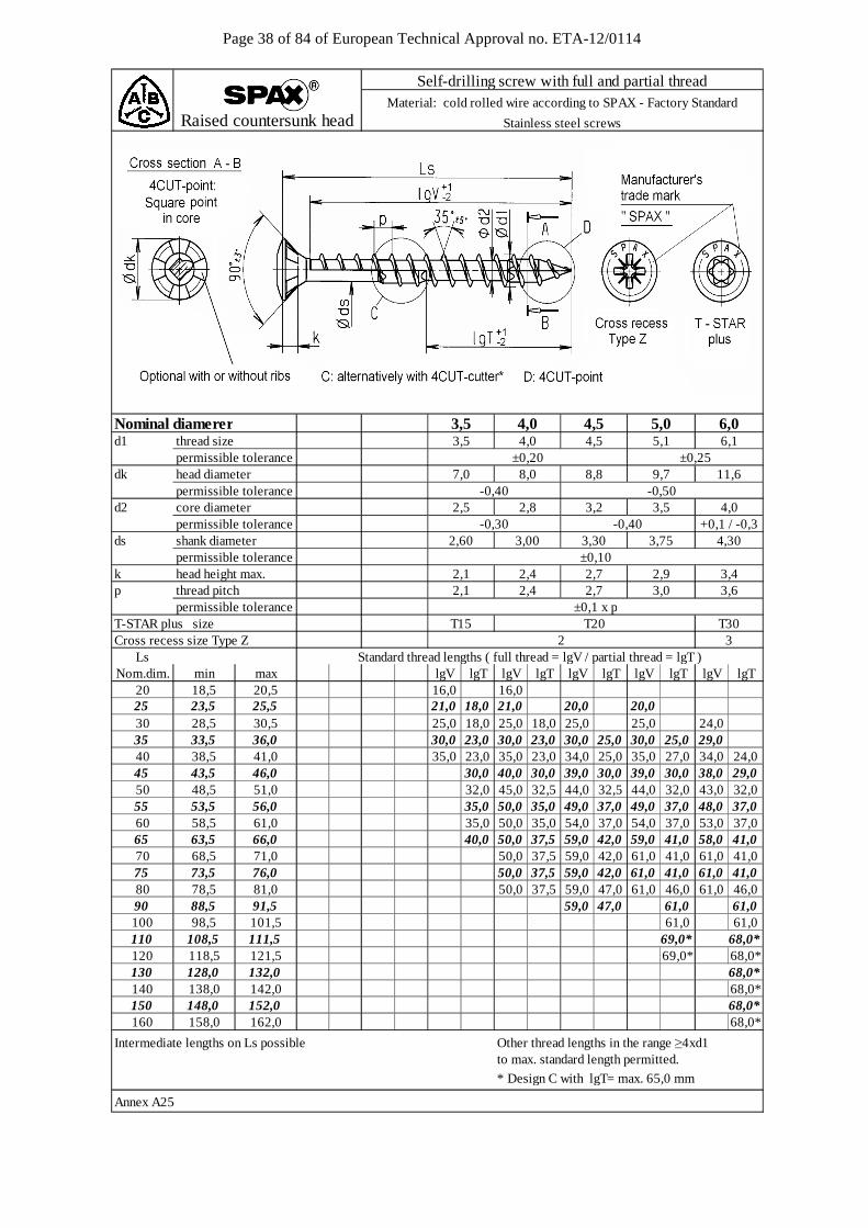
Page 38 of 84 of European Technical Approval no. ETA-12/0114
d1 thread size permissible tolerancedk head diameter permissible toleranced2 core diameter
permissible toleranceds shank diameter 2,60 3,00 3,30 3,75 4,30
permissible tolerancek head height max. 2,1 2,4 2,7 2,9 3,4p thread pitch permissible toleranceT-STAR plus size T15 T30Cross recess size Type Z 2 3
LsNom.dim. min max lgV lgT lgV lgT lgV lgT lgV lgT lgV lgT
20 18,5 20,5 16,0 16,025 23,5 25,5 21,0 18,0 21,0 20,0 20,030 28,5 30,5 25,0 18,0 25,0 18,0 25,0 25,0 24,035 33,5 36,0 30,0 23,0 30,0 23,0 30,0 25,0 30,0 25,0 29,040 38,5 41,0 35,0 23,0 35,0 23,0 34,0 25,0 35,0 27,0 34,0 24,045 43,5 46,0 30,0 40,0 30,0 39,0 30,0 39,0 30,0 38,0 29,050 48,5 51,0 32,0 45,0 32,5 44,0 32,5 44,0 32,0 43,0 32,055 53,5 56,0 35,0 50,0 35,0 49,0 37,0 49,0 37,0 48,0 37,060 58,5 61,0 35,0 50,0 35,0 54,0 37,0 54,0 37,0 53,0 37,065 63,5 66,0 40,0 50,0 37,5 59,0 42,0 59,0 41,0 58,0 41,070 68,5 71,0 50,0 37,5 59,0 42,0 61,0 41,0 61,0 41,075 73,5 76,0 50,0 37,5 59,0 42,0 61,0 41,0 61,0 41,080 78,5 81,0 50,0 37,5 59,0 47,0 61,0 46,0 61,0 46,090 88,5 91,5 59,0 47,0 61,0 61,0100 98,5 101,5 61,0 61,0110 108,5 111,5 69,0* 68,0*120 118,5 121,5 69,0* 68,0*130 128,0 132,0 68,0*140 138,0 142,0 68,0*150 148,0 152,0 68,0*160 158,0 162,0 68,0*
Intermediate lengths on Ls possible Other thread lengths in the range ≥4xd1to max. standard length permitted.
* Design C with lgT= max. 65,0 mm
Annex A25
3,2
Raised countersunk head
-0,40
4,0
-0,50
4,5
±0,10
-0,30 -0,40
2,7 3,0 3,6±0,1 x p
+0,1 / -0,3
2,1
Standard thread lengths ( full thread = lgV / partial thread = lgT )
5,1
T20
6,1
7,0
4,02,5 3,52,8
2,4
Nominal diamerer
11,6
3,5
8,0 8,8 9,7±0,20 ±0,25
6,03,5 4,0 4,5
Self-drilling screw with full and partial threadMaterial: cold rolled wire according to SPAX - Factory Standard
Stainless steel screws
5,0
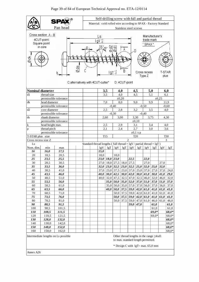
Page 39 of 84 of European Technical Approval no. ETA-12/0114
d1 thread size permissible tolerancedk head diameter permissible toleranced2 core diameter
permissible toleranceds shank diameter 2,60 3,00 3,30 3,75 4,30
permissible tolerancek head height max.p thread pitch permissible toleranceT-STAR plus size T15 T30Cross recess size Z 2 3
LsNom. dim. min max lgV lgT lgV lgT lgV lgT lgV lgT lgV lgT
16 16,0 17,5 15,020 18,5 20,5 18,0 18,025 23,5 25,5 23,0 18,0 23,0 22,5 22,030 28,5 30,5 27,0 18,0 27,5 18,0 27,5 27,0 27,035 33,5 36,0 32,0 23,0 32,5 23,0 32,5 25,0 32,0 25,0 32,040 38,5 41,0 37,0 23,0 37,5 23,0 37,0 25,0 37,0 27,0 37,0 24,045 43,5 46,0 40,0 30,0 42,5 30,0 42,0 30,0 41,0 30,0 41,0 29,050 48,5 51,0 40,0 32,0 47,5 32,5 47,0 32,5 46,0 32,0 46,0 32,055 53,5 56,0 35,0 50,0 35,0 52,0 37,0 51,0 37,0 51,0 37,060 58,5 61,0 35,0 50,0 35,0 57,0 37,0 56,0 37,0 56,0 37,065 63,5 66,0 40,0 50,0 37,5 59,0 42,0 61,0 41,0 61,0 41,070 68,5 71,0 50,0 37,5 59,0 42,0 61,0 41,0 61,0 41,075 73,5 76,0 50,0 37,5 59,0 42,0 61,0 41,0 61,0 41,080 78,5 81,0 50,0 37,5 59,0 47,0 61,0 46,0 61,0 46,090 88,5 91,5 59,0 47,0 61,0 61,0100 98,5 101,5 61,0 61,0110 108,5 111,5 69,0* 68,0*120 118,5 121,5 69,0* 68,0*130 128,0 132,0 68,0*140 138,0 142,0 68,0*150 148,0 152,0 68,0*160 158,0 162,0 68,0*
Other thread lengths in the range ≥4xd1to max. standard length permitted.
* Design C with lgT= max. 65,0 mm
Annex A26
3,5-0,40 -0,50
9,0 9,9 11,9
3,0
-0,60
3,55,15,0 6,0
6,1
3,6
7,0
±0,10
4,54,0
8,0
2,8 3,2
2,1 2,4 2,7
2,5
4,0 4,5
Pan head
Nominal diameter
3,4 4,0
Standard thread lengths ( full thread = lgV / partial thread = lgT )
2,5 2,9 3,1
T20
Intermediate lengths on Ls possible
±0,1 x p
±0,25
Self-drilling screw with full and partial threadMaterial: cold rolled wire according to SPAX - Factory Standard
Stainless steel screws
-0,40-0,304,0
±0,203,5
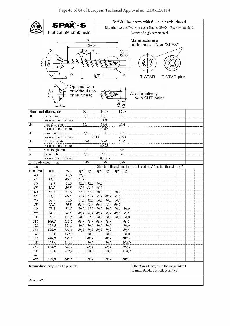
Page 40 of 84 of European Technical Approval no. ETA-12/0114
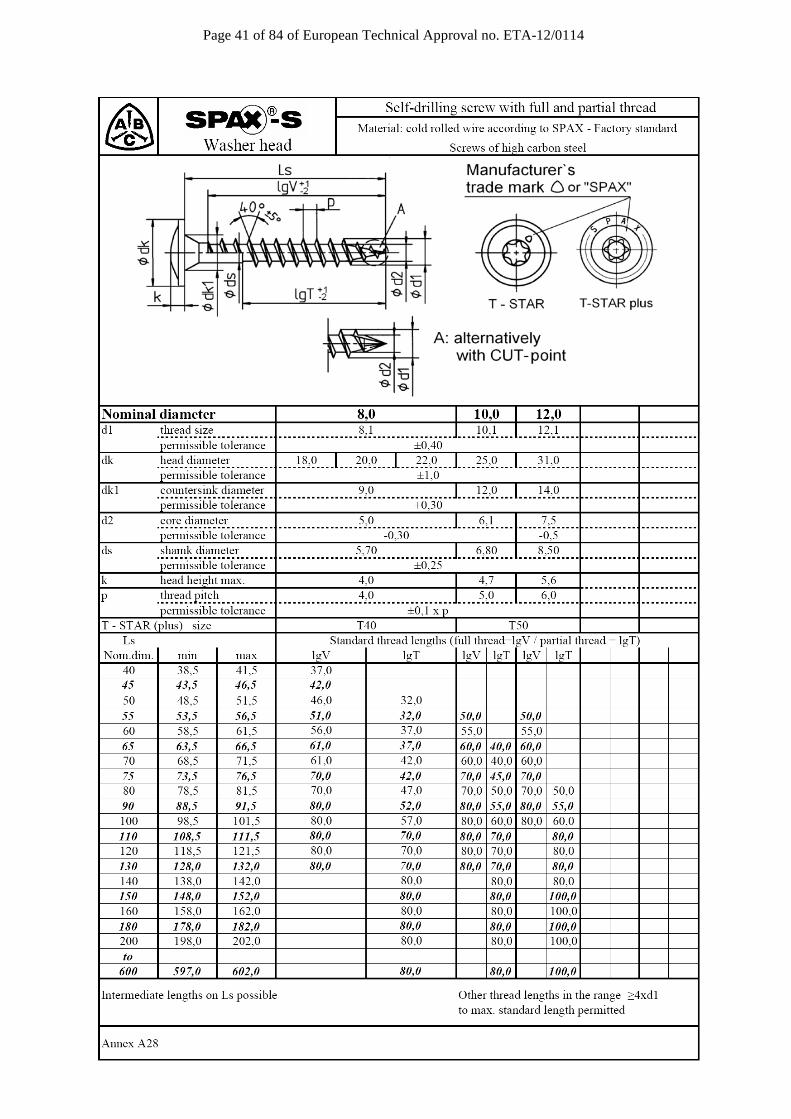
Page 41 of 84 of European Technical Approval no. ETA-12/0114

Page 42 of 84 of European Technical Approval no. ETA-12/0114

Page 43 of 84 of European Technical Approval no. ETA-12/0114
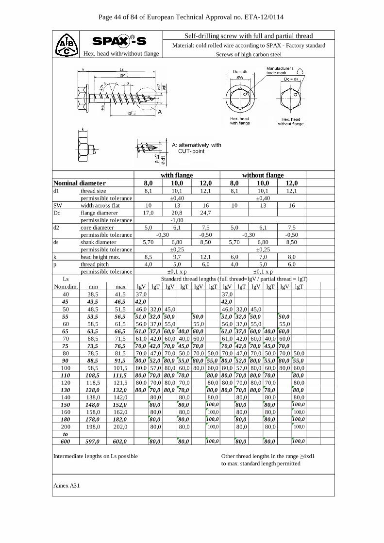
Page 44 of 84 of European Technical Approval no. ETA-12/0114
d1 thread size permissible toleranceSW width across flatDc flange diamerer
permissible toleranced2 core diameter
permissible toleranceds shank diameter
permissible tolerancek head height max.p thread pitch permissible tolerance
LsNom.dim. min max lgV lgT lgV lgT lgV lgT lgV lgT lgV lgT lgV lgT
40 38,5 41,5 37,0 37,045 43,5 46,5 42,0 42,050 48,5 51,5 46,0 32,0 45,0 46,0 32,0 45,055 53,5 56,5 51,0 32,0 50,0 50,0 51,0 32,0 50,0 50,060 58,5 61,5 56,0 37,0 55,0 55,0 56,0 37,0 55,0 55,065 63,5 66,5 61,0 37,0 60,0 40,0 60,0 61,0 37,0 60,0 40,0 60,070 68,5 71,5 61,0 42,0 60,0 40,0 60,0 61,0 42,0 60,0 40,0 60,075 73,5 76,5 70,0 42,0 70,0 45,0 70,0 70,0 42,0 70,0 45,0 70,080 78,5 81,5 70,0 47,0 70,0 50,0 70,0 50,0 70,0 47,0 70,0 50,0 70,0 50,090 88,5 91,5 80,0 52,0 80,0 55,0 80,0 55,0 80,0 52,0 80,0 55,0 80,0 55,0100 98,5 101,5 80,0 57,0 80,0 60,0 80,0 60,0 80,0 57,0 80,0 60,0 80,0 60,0110 108,5 111,5 80,0 70,0 80,0 70,0 80,0 80,0 70,0 80,0 70,0 80,0120 118,5 121,5 80,0 70,0 80,0 70,0 80,0 80,0 70,0 80,0 70,0 80,0130 128,0 132,0 80,0 70,0 80,0 70,0 80,0 80,0 70,0 80,0 70,0 80,0140 138,0 142,0 80,0 80,0 80,0 80,0 80,0 80,0150 148,0 152,0 80,0 80,0 100,0 80,0 80,0 100,0
160 158,0 162,0 80,0 80,0 100,0 80,0 80,0 100,0
180 178,0 182,0 80,0 80,0 100,0 80,0 80,0 100,0
200 198,0 202,0 80,0 80,0 100,0 80,0 80,0 100,0
to 600 597,0 602,0 80,0 80,0 100,0 80,0 80,0 100,0
Intermediate lengths on Ls possible Other thread lengths in the range ≥4xd1to max. standard length permitted
Annex A31
without flangewith flange
Self-drilling screw with full and partial threadMaterial: cold rolled wire according to SPAX - Factory standard
Screws of high carbon steelHex. head with/without flange
Nominal diameter 8,0 10,0 12,0 10,0 12,0
±0,1 x p
10,18,1
10
5,0
8,50
12,1±0,25
-0,30
13
6,15,0
8,0
-0,50
±0,256,0
-1,00
-0,507,5
8,012,1
1624,7
1017,0 20,8
6,04,0
6,80
9,75,0
5,70
8,5
±0,40
6,0
±0,40
6,1
4,0
-0,30
5,07,0
5,70 6,80
±0,1 x p
12,1
16
7,5
8,50
Standard thread lengths (full thread=lgV / partial thread = lgT)
10,1
13
8,1
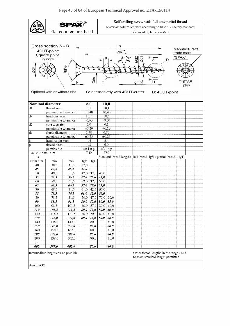
Page 45 of 84 of European Technical Approval no. ETA-12/0114

Page 46 of 84 of European Technical Approval no. ETA-12/0114
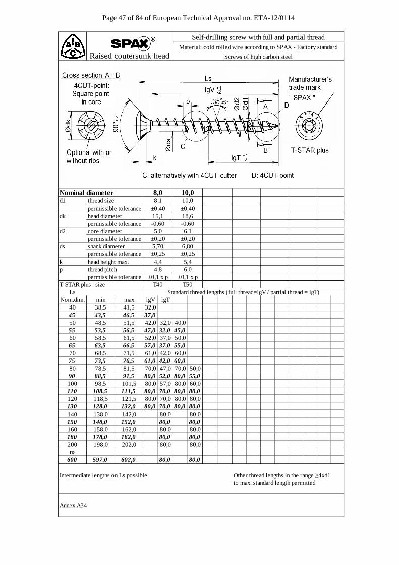
Page 47 of 84 of European Technical Approval no. ETA-12/0114
d1 thread size permissible tolerancedk head diameter permissible toleranced2 core diameter
permissible toleranceds shank diameter
permissible tolerancek head height max.p thread pitch permissible toleranceT-STAR plus size
LsNom.dim. min max lgV lgT
40 38,5 41,5 32,045 43,5 46,5 37,050 48,5 51,5 42,0 32,0 40,055 53,5 56,5 47,0 32,0 45,060 58,5 61,5 52,0 37,0 50,065 63,5 66,5 57,0 37,0 55,070 68,5 71,5 61,0 42,0 60,075 73,5 76,5 61,0 42,0 60,080 78,5 81,5 70,0 47,0 70,0 50,090 88,5 91,5 80,0 52,0 80,0 55,0100 98,5 101,5 80,0 57,0 80,0 60,0110 108,5 111,5 80,0 70,0 80,0 80,0120 118,5 121,5 80,0 70,0 80,0 80,0130 128,0 132,0 80,0 70,0 80,0 80,0140 138,0 142,0 80,0 80,0150 148,0 152,0 80,0 80,0160 158,0 162,0 80,0 80,0180 178,0 182,0 80,0 80,0200 198,0 202,0 80,0 80,0to
600 597,0 602,0 80,0 80,0
Intermediate lengths on Ls possible Other thread lengths in the range ≥4xd1to max. standard length permitted
Annex A34
6,80±0,255,46,0
±0,1 x pT50
5,0
5,70
10,010,0±0,4018,6-0,606,1
±0,20±0,20
Raised coutersunk head
Standard thread lengths (full thread=lgV / partial thread = lgT)
±0,25
±0,1 x p
Nominal diameter 8,0
-0,60
8,1
15,1
4,44,8
T40
Self-drilling screw with full and partial threadMaterial: cold rolled wire according to SPAX - Factory standard
Screws of high carbon steel
±0,40
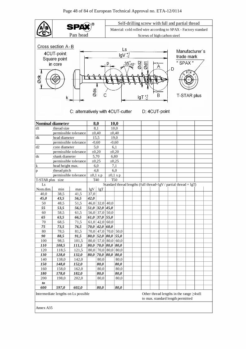
Page 48 of 84 of European Technical Approval no. ETA-12/0114
d1 thread size permissible tolerancedk head diameter permissible toleranced2 core diameter
permissible toleranceds shank diameter
permissible tolerancek head height max.p thread pitch permissible toleranceT-STAR plus size
LsNom.dim. min max lgV lgT
40,0 38,5 41,5 37,045,0 43,5 56,5 42,050 48,5 51,5 46,0 32,0 40,055 53,5 56,5 51,0 32,0 45,060 58,5 61,5 56,0 37,0 50,065 63,5 66,5 61,0 37,0 55,070 68,5 71,5 61,0 42,0 60,075 73,5 76,5 70,0 42,0 60,080 78,5 81,5 70,0 47,0 70,0 50,090 88,5 91,5 80,0 52,0 80,0 55,0100 98,5 101,5 80,0 57,0 80,0 60,0110 108,5 111,5 80,0 70,0 80,0 80,0120 118,5 121,5 80,0 70,0 80,0 80,0130 128,0 132,0 80,0 70,0 80,0 80,0140 138,0 142,0 80,0 80,0150 148,0 152,0 80,0 80,0160 158,0 162,0 80,0 80,0180 178,0 182,0 80,0 80,0200 198,0 202,0 80,0 80,0to
600 597,0 602,0 80,0 80,0
Intermediate lengths on Ls possible Other thread lengths in the range ≥4xd1to max. standard length permitted
Annex A35
6,80±0,257,16,0
±0,1 x pT50
10,0±0,4019,0-0,606,1
±0,20
T40
-0,60
8,1
15,5±0,40
Self-drilling screw with full and partial threadMaterial: cold rolled wire according to SPAX - Factory standard
Screws of high carbon steelPan head
10,0
5,70
6,04,8
Standard thread lengths (full thread=lgV / partial thread = lgT)
±0,25
±0,1 x p
Nominal diameter 8,0
5,0±0,20

Page 49 of 84 of European Technical Approval no. ETA-12/0114
without flange without flange
d1 thread size permissible toleranceSW wrench sizeDc flange diameter permissible toleranced2 core diameter
permissible toleranceds shank diameter
permissible tolerancek head height max.p thread pitch permissible tolerance
LsNom.dim. min max lgV lgT
40 38,5 41,5 32,0 32,045 43,5 46,5 37,0 37,050 48,5 51,5 42,0 32,0 42,0 32,0 40,0 40,055 53,5 56,5 47,0 32,0 47,0 32,0 45,0 45,060 58,5 61,5 52,0 37,0 52,0 37,0 50,0 50,065 63,5 66,5 57,0 37,0 57,0 37,0 55,0 55,070 68,5 71,5 61,0 42,0 61,0 42,0 60,0 60,075 73,5 76,5 61,0 42,0 61,0 42,0 60,0 60,080 78,5 81,5 70,0 47,0 70,0 47,0 70,0 50,0 70,0 50,090 88,5 91,5 80,0 52,0 80,0 52,0 80,0 55,0 80,0 55,0100 98,5 101,5 80,0 57,0 80,0 57,0 80,0 60,0 80,0 60,0110 108,5 111,5 80,0 70,0 80,0 70,0 80,0 80,0 80,0 80,0120 118,5 121,5 80,0 70,0 80,0 70,0 80,0 80,0 80,0 80,0130 128,0 132,0 80,0 70,0 80,0 70,0 80,0 80,0 80,0 80,0140 138,0 142,0 80,0 80,0 80,0 80,0150 148,0 152,0 80,0 80,0 80,0 80,0160 158,0 162,0 80,0 80,0 80,0 80,0180 178,0 182,0 80,0 80,0 80,0 80,0200 198,0 202,0 80,0 80,0 80,0 80,0to
600 597,0 602,0 80,0 80,0 80,0 80,0
Intermediate lengths on Ls possible Other thread lengths in the range ≥4xd1to max. standard length permitted
Annex A36
9,7 7,06,0 6,0
±0,1 x p ±0,1 x p
±0,20 ±0,206,80 6,80±0,25 ±0,25
20,8 --1,00 -6,1 6,1
10,0 10,0±0,40 ±0,40
13 13
±0,254,4 4,4
±0,25
Standard thread lengths (full thread=lgV / partial thread = lgT)
4,8 4,8±0,1 x p ±0,1 x p
±0,20 ±0,205,70 5,70
-1,0017,0
±0,40
--
5,0 5,0
8,1 8,18,0
±0,4010 10
with flange
Self-drilling screw with full and partial threadMaterial: cold rolled wire according to SPAX - Factory standard
Hex. Head with/without flange Screws of high carbon steel
Nominal diameter 8,0with flange
10,0 10,0
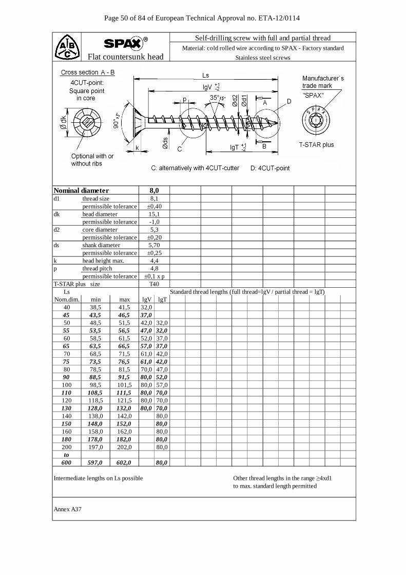
Page 50 of 84 of European Technical Approval no. ETA-12/0114
d1 thread size permissible tolerancedk head diameter permissible toleranced2 core diameter
permissible toleranceds shank diameter
permissible tolerancek head height max.p thread pitch permissible toleranceT-STAR plus size
LsNom.dim. min max lgV lgT
40 38,5 41,5 32,045 43,5 46,5 37,050 48,5 51,5 42,0 32,055 53,5 56,5 47,0 32,060 58,5 61,5 52,0 37,065 63,5 66,5 57,0 37,070 68,5 71,5 61,0 42,075 73,5 76,5 61,0 42,080 78,5 81,5 70,0 47,090 88,5 91,5 80,0 52,0100 98,5 101,5 80,0 57,0110 108,5 111,5 80,0 70,0120 118,5 121,5 80,0 70,0130 128,0 132,0 80,0 70,0140 138,0 142,0 80,0150 148,0 152,0 80,0160 158,0 162,0 80,0180 178,0 182,0 80,0200 197,0 202,0 80,0to
600 597,0 602,0 80,0
Intermediate lengths on Ls possible Other thread lengths in the range ≥4xd1to max. standard length permitted
Annex A37
Standard thread lengths (full thread=lgV / partial thread = lgT)
4,8±0,1 x p
T40
5,70±0,254,4
5,3±0,20
±0,4015,1-1,0
Nominal diameter 8,08,1
Self-drilling screw with full and partial threadMaterial: cold rolled wire according to SPAX - Factory standard
Flat countersunk head Stainless steel screws

Page 51 of 84 of European Technical Approval no. ETA-12/0114
d1 thread size permissible tolerancedk head diameter permissible tolerancedk1 countersink diameter
permissible toleranced2 core diameter
permissible toleranceds shank diameter
permissible tolerancek head height max.p thread pitch permissible toleranceT-STAR plus size
LsNom.dim. min max
40 37,5 41,545 43,5 46,550 48,5 51,555 53,5 56,560 58,5 61,565 63,5 66,570 68,5 71,575 73,5 76,580 78,5 81,590 88,5 91,5100 98,5 101,5110 108,5 111,5120 118,5 121,5130 128,0 132,0140 138,0 142,0150 148,0 152,0160 158,0 162,0180 178,0 182,0200 197,0 202,0to
600 597,0 602,0
Intermediate lengths on Ls possible Other thread lengths in the range ≥4xd1 = Preferred size to max. standard length permitted
Annex A38
37,0
80,080,0
70,070,0
42,047,0
80,0
80,0
80,0
80,080,0
70,070,0
80,0 70,080,0
80,080,0
52,057,0
±0,40
37,061,061,0
37,042,0
42,0
lgTlgV
Self-drilling screw with full and partial threadMaterial: cold rolled wire according to SPAX - Factory standard
Washer head Stainless steel screws
Nominal diameter
18,0 22,020,0
8,08,1
±1,024,0
5,70
Standard thread lengths (full thread=lgV / partial thread = lgT)
±0,254,3
T40
4,8±0,1 x p
9,00+0,50
5,3±0,20
46,0 32,051,056,0
32,0
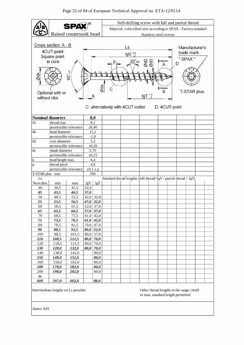
Page 52 of 84 of European Technical Approval no. ETA-12/0114
d1 thread size permissible tolerancedk head diameter permissible toleranced2 core diameter
permissible toleranceds shank diameter
permissible tolerancek head height max.p thread pitch permissible toleranceT-STAR plus size
LsNom.dim. min max lgV lgT
40 38,5 41,5 32,045 43,5 46,5 37,050 48,5 51,5 42,0 32,055 53,5 56,5 47,0 32,060 58,5 61,5 52,0 37,065 63,5 66,5 57,0 37,070 68,5 71,5 61,0 42,075 73,5 76,5 61,0 42,080 78,5 81,5 70,0 47,090 88,5 91,5 80,0 52,0100 98,5 101,5 80,0 57,0110 108,5 111,5 80,0 70,0120 118,5 121,5 80,0 70,0130 128,0 132,0 80,0 70,0140 138,0 142,0 80,0150 148,0 152,0 80,0160 158,0 162,0 80,0180 178,0 182,0 80,0200 198,0 202,0 80,0to
600 597,0 602,0 80,0
Intermediate lengths on Ls possible Other thread lengths in the range ≥4xd1to max. standard length permitted
Annex A39
Standard thread lengths (full thread=lgV / partial thread = lgT)
4,8±0,1 x p
T40
5,70±0,254,4
5,3±0,20
±0,4015,1-1,0
Nominal diameter 8,08,1
Self-drilling screw with full and partial threadMaterial: cold rolled wire according to SPAX - Factory standard
Raised coutersunk head Stainless steel screws
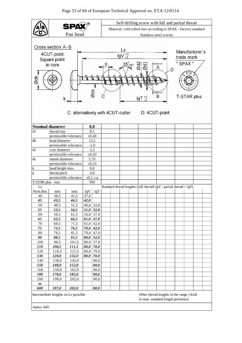
Page 53 of 84 of European Technical Approval no. ETA-12/0114
d1 thread size permissible tolerancedk head diameter permissible toleranced2 core diameter
permissible toleranceds shamk diameter
permissible tolerancek head height max.p thread pitch permissible toleranceT-STAR plus size
LsNom.dim. min max lgV lgT
40 38,5 41,5 37,045 43,5 46,5 42,050 48,5 51,5 46,0 32,055 53,5 56,5 51,0 32,060 58,5 61,5 56,0 37,065 63,5 66,5 61,0 37,070 68,5 71,5 61,0 42,075 73,5 76,5 70,0 42,080 78,5 81,5 70,0 47,090 88,5 91,5 80,0 52,0100 98,5 101,5 80,0 57,0110 108,5 111,5 80,0 70,0120 118,5 121,5 80,0 70,0130 128,0 132,0 80,0 70,0140 138,0 142,0 80,0150 148,0 152,0 80,0160 158,0 162,0 80,0180 178,0 182,0 80,0200 198,0 202,0 80,0to
600 597,0 202,0 80,0
Intermediate lengths on Ls possible Other thread lengths in the range ≥4xd1to max. standard length permitted
Annex A40
Self-drilling screw with full and partial threadMaterial: cold rolled wire according to SPAX - Factory standard
Pan head Stainless steel screws
Nominal diameter 8,08,1
±0,4015,5-1,05,3
±0,205,70±0,256,0
Standard thread lengths (full thread=lgV / partial thread = lgT)
4,8±0,1 x p
T40
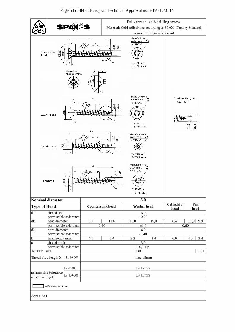
Page 54 of 84 of European Technical Approval no. ETA-12/0114
Nominal diameter
d1 thread size permissible tolerancedk head diameter 9,7 13,0 11,9 9,9 permissible toleranced2 core diameter
permissible tolerancek head height max. 4,0 3,4p thread pitch
permissible toleranceT-STAR size T20
=Preferred size
Annex A41
-0,60 ±1,0 -0,60
Full- thread, self-drilling screwMaterial: Cold rolled wire according to SPAX - Factory Standard
Screws of high-carbon steel
6,0Cylindric Pan
headType of Head Countersunk head Washer head head
6,0±0,20
11,6 15,0 8,4
Thread-free length X
4,0-0,40
4,0 5,0 2,2 2,4 6,03,0
±0,1 x pT30
Ls 60-200 max. 15mm
permissible toleranceLs 60-99 Ls ±2mm
Ls 100-200 Ls ±5mmof screw length
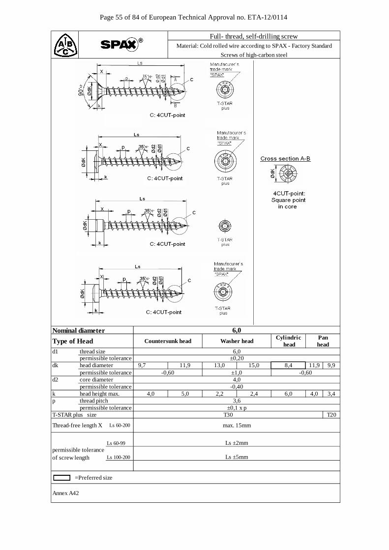
Page 55 of 84 of European Technical Approval no. ETA-12/0114
Nominal diameter
d1 thread size permissible tolerancedk head diameter 9,7 11,9 9,9 permissible toleranced2 core diameter
permissible tolerancek head height max. 4,0 3,4p thread pitch
permissible toleranceT-STAR plus size T20
=Preferred size
Annex A42
Full- thread, self-drilling screwMaterial: Cold rolled wire according to SPAX - Factory Standard
Screws of high-carbon steel
6,0
Type of Head Cylindric
Ls 60-200 max. 15mm
6,0±0,20
Pan head head
Countersunk head Washer head
4,0-0,40
4,0 5,0 2,2 2,4 6,0
15,0
permissible toleranceLs 60-99 Ls ±2mm
Ls 100-200 Ls ±5mmof screw length
Thread-free length X
8,4
3,6±0,1 x p
T30
13,0-0,60-0,60 ±1,0
11,9
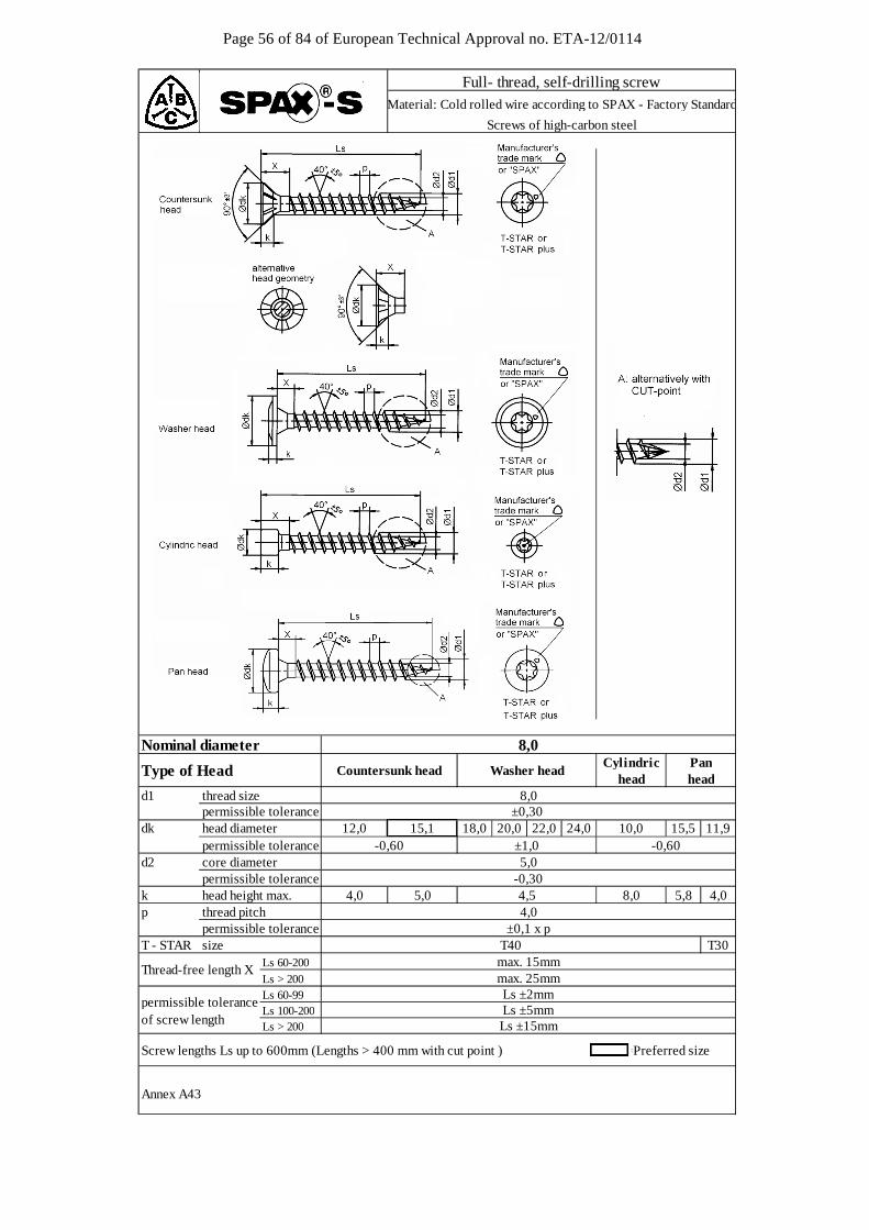
Page 56 of 84 of European Technical Approval no. ETA-12/0114
Nominal diameter
d1 thread size permissible tolerancedk head diameter 18,0 20,0 22,0 24,0 15,5 11,9 permissible toleranced2 core diameter
permissible tolerancek head height max. 5,8 4,0p thread pitch
permissible toleranceT - STAR size T30
Ls 60-200Ls > 200
Screw lengths Ls up to 600mm (Lengths > 400 mm with cut point ) =Preferred size
Annex A43
permissible toleranceof screw length
Thread-free length Xmax. 15mmmax. 25mm
Ls 60-99Ls 100-200Ls > 200
Ls ±5mmLs ±2mm
-0,30
Ls ±15mm
T40
Type of Head
5,0 4,54,0
Washer headPan
±0,1 x p
Full- thread, self-drilling screwMaterial: Cold rolled wire according to SPAX - Factory Standard
Screws of high-carbon steel
10,0
head
8,0
headCylindric
-0,6015,112,0
Countersunk head
8,0
8,04,0
-0,60±1,05,0
±0,30
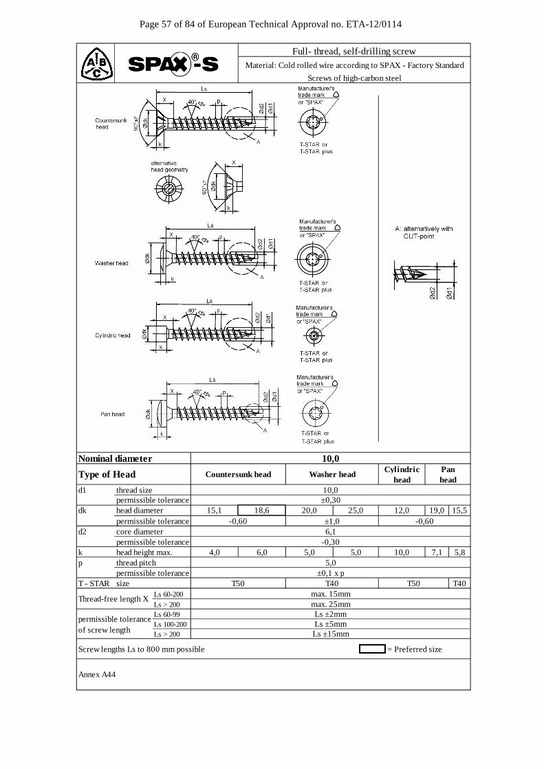
Page 57 of 84 of European Technical Approval no. ETA-12/0114
d1 thread size permissible tolerancedk head diameter 19,0 15,5 permissible toleranced2 core diameter
permissible tolerancek head height max. 7,1 5,8p thread pitch
permissible toleranceT - STAR size T40
Ls 60-200Ls > 200
Screw lengths Ls to 800 mm possible
Annex A44
±0,1 x p
Type of Headhead
Ls ±2mm
Thread-free length Xmax. 25mm
5,0
permissible toleranceLs 60-99
T50
Ls 100-200 Ls ±5mm
T50
= Preferred size
of screw length Ls > 200
-0,30
max. 15mm
4,0 6,0 5,0
Ls ±15mm
10,05,0
T40
6,1
25,015,1 20,018,6 12,0-0,60 ±1,0 -0,60
10,0
10,0Cylindric
±0,30
Panhead
Nominal diameter
Full- thread, self-drilling screwMaterial: Cold rolled wire according to SPAX - Factory Standard
Screws of high-carbon steel
Countersunk head Washer head
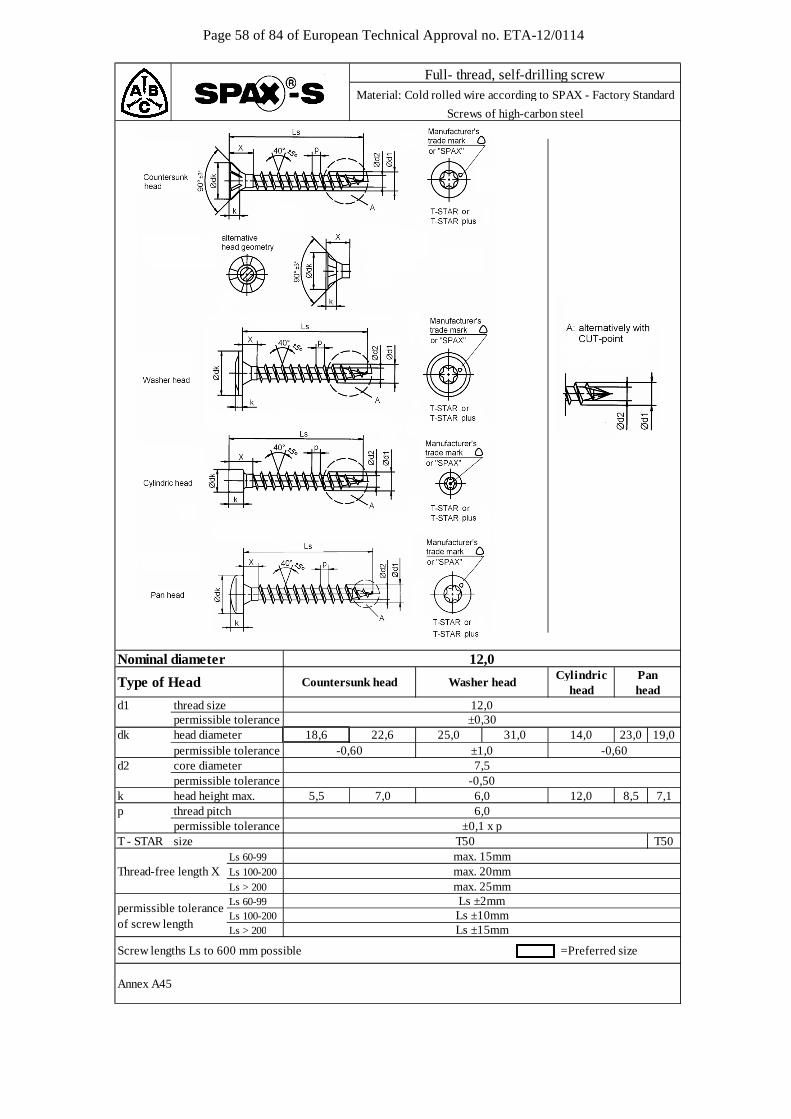
Page 58 of 84 of European Technical Approval no. ETA-12/0114
Nominal diameter
d1 thread size permissible tolerancedk head diameter 23,0 19,0 permissible toleranced2 core diameter
permissible tolerancek head height max. 8,5 7,1p thread pitch
permissible toleranceT - STAR size T50
Ls 60-99Ls 100-200
Ls > 200
Screw lengths Ls to 600 mm possible =Preferred size
Annex A45
Panhead
Countersunk head Washer head
Full- thread, self-drilling screwMaterial: Cold rolled wire according to SPAX - Factory Standard
Screws of high-carbon steel
12,0
Type of Headhead
Cylindric
-0,507,5
6,0±0,1 x p
max. 20mm
12,0
18,6 25,0±0,30
22,6-0,60 ±1,0 -0,60
31,0 14,0
permissible toleranceLs 60-99
5,5 7,0
Ls ±2mmLs 100-200 Ls ±10mm
of screw lengthLs > 200 Ls ±15mm
Thread-free length Xmax. 15mm
max. 25mm
T50
12,06,0
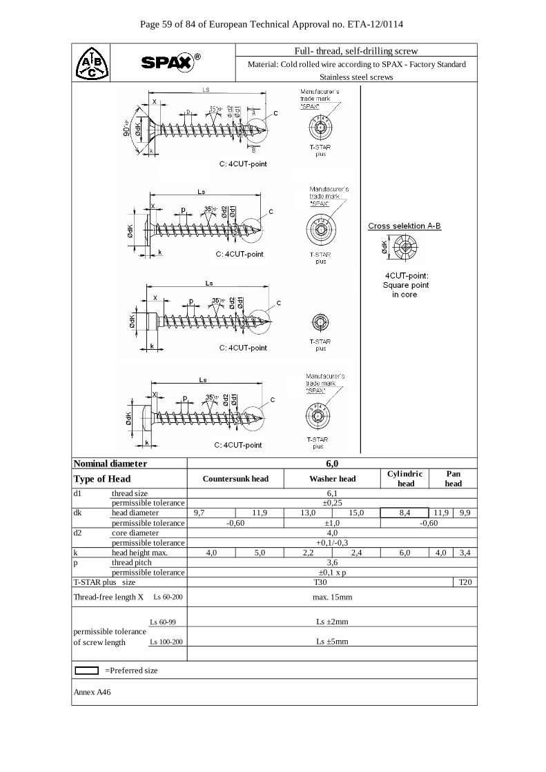
Page 59 of 84 of European Technical Approval no. ETA-12/0114
d1 thread size permissible tolerancedk head diameter 9,7 11,9 9,9 permissible toleranced2 core diameter
permissible tolerancek head height max. 4,0 3,4p thread pitch
permissible toleranceT-STAR plus size T20
=Preferred size
Annex A46
Full- thread, self-drilling screwMaterial: Cold rolled wire according to SPAX - Factory Standard
Stainless steel screws
6,0
Type of Head CylindricNominal diameter
Ls 60-200 max. 15mm
6,1±0,25
Pan head headCountersunk head Washer head
4,0+0,1/-0,3
4,0 5,0 2,2 2,4 6,0
15,0
permissible toleranceLs 60-99 Ls ±2mm
Ls 100-200 Ls ±5mmof screw length
Thread-free length X
8,4
3,6±0,1 x p
T30
13,0-0,60-0,60 ±1,0
11,9
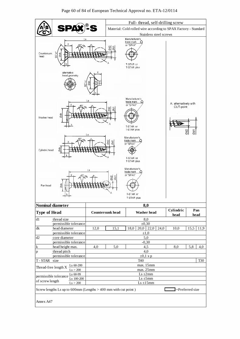
Page 60 of 84 of European Technical Approval no. ETA-12/0114
Nominal diameter
d1 thread size permissible tolerancedk head diameter 18,0 20,0 22,0 24,0 15,5 11,9 permissible toleranced2 core diameter
permissible tolerancek head height max. 5,8 4,0p thread pitch
permissible toleranceT - STAR size T30
Ls 60-200Ls > 200
Screw lengths Ls up to 600mm (Lengths > 400 mm with cut point ) =Preferred size
Annex A47
permissible toleranceof screw length
Thread-free length Xmax. 15mmmax. 25mm
Ls 60-99Ls 100-200Ls > 200
Ls ±5mmLs ±2mm
-0,30
Ls ±15mm
T40
Type of Head
5,0 4,54,0
Washer head
±0,1 x p
Full- thread, self-drilling screwMaterial: Cold rolled wire according to SPAX Factory - Standard
Stainless steel screws
10,0
head
8,0
headCylindric
±1,015,112,0
Countersunk head
8,0
8,04,0
5,0
±0,30
Pan
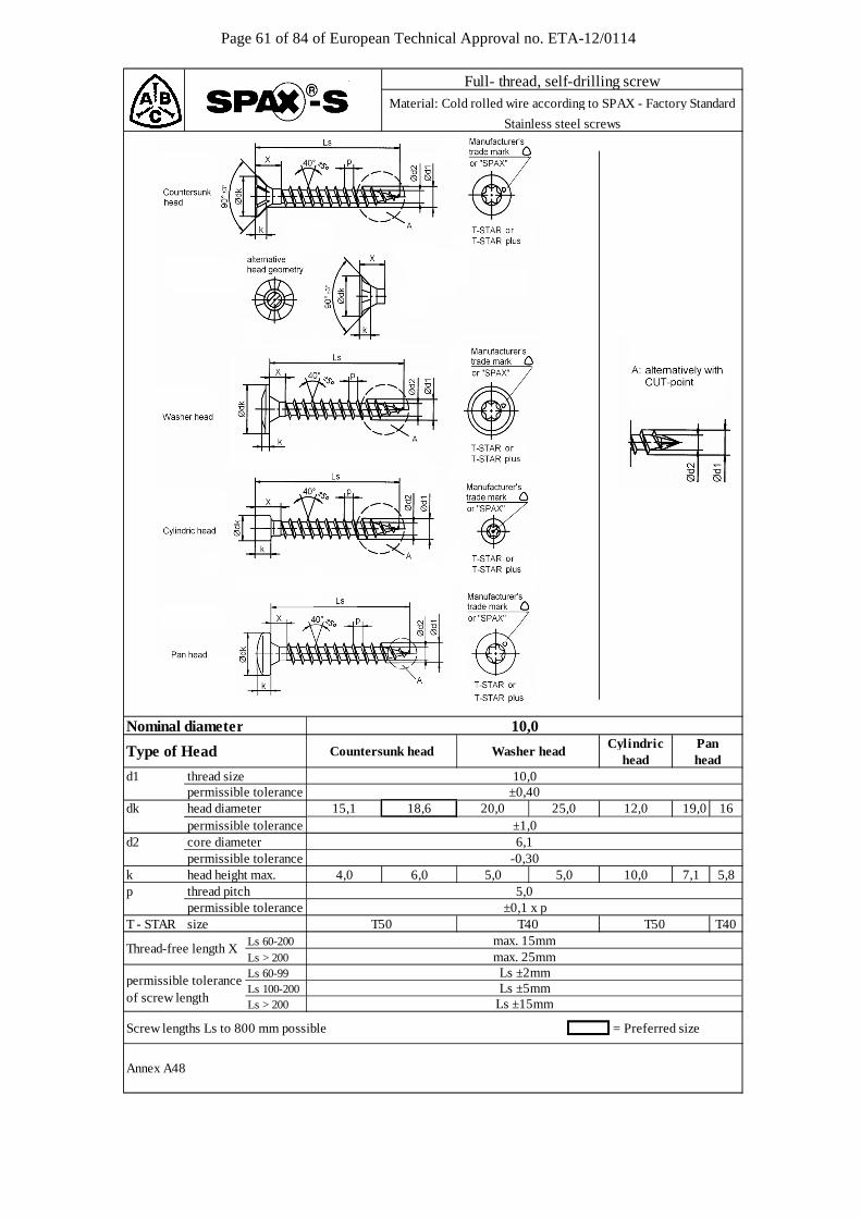
Page 61 of 84 of European Technical Approval no. ETA-12/0114
d1 thread size permissible tolerancedk head diameter 19,0 16 permissible toleranced2 core diameter
permissible tolerancek head height max. 7,1 5,8p thread pitch
permissible toleranceT - STAR size T40
Ls 60-200Ls > 200
Screw lengths Ls to 800 mm possible
Annex A48
= Preferred size
±0,1 x p
Ls 100-200 Ls ±5mm
Type of Head
±1,0
max. 25mm
5,05,0
T50
Nominal diameter
permissible toleranceLs 60-99
of screw length Ls > 200
Thread-free length X
T40 T50
-0,30
max. 15mm
4,0 6,0 5,0
Ls ±15mm
10,0
Ls ±2mm
±0,40
Panhead
6,1
25,015,1 20,018,6 12,0
Full- thread, self-drilling screwMaterial: Cold rolled wire according to SPAX - Factory Standard
Stainless steel screws
Countersunk head Washer head
10,0
10,0Cylindric
head
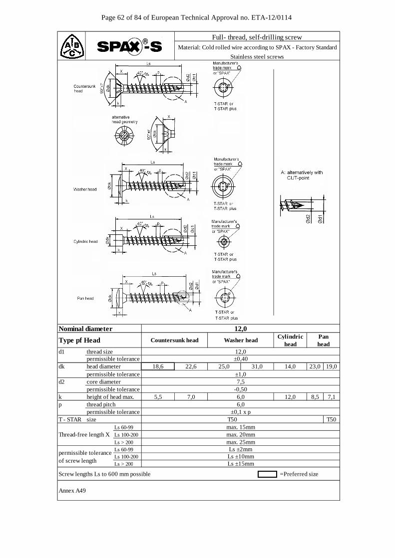
Page 62 of 84 of European Technical Approval no. ETA-12/0114
d1 thread size permissible tolerancedk head diameter 23,0 19,0 permissible toleranced2 core diameter
permissible tolerancek height of head max. 8,5 7,1p thread pitch
permissible toleranceT - STAR size T50
Ls 60-99Ls 100-200
Ls > 200
Screw lengths Ls to 600 mm possible =Preferred size
Annex A49
±1,0
Nominal diameter
Thread-free length Xmax. 15mm
max. 25mm
T50
12,06,0
18,6 25,0
permissible toleranceLs 60-99
5,5 7,0
Ls ±2mmLs 100-200 Ls ±10mm
of screw lengthLs > 200
22,6 31,0 14,0
Type pf Headhead
Cylindric
12,0
Panhead
±0,40
-0,507,5
6,0±0,1 x p
max. 20mm
Ls ±15mm
Countersunk head Washer head
Full- thread, self-drilling screwMaterial: Cold rolled wire according to SPAX - Factory Standard
Stainless steel screws
12,0
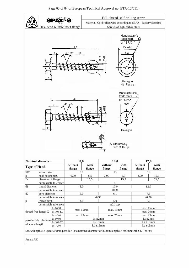
Page 63 of 84 of European Technical Approval no. ETA-12/0114
Nominal diameter
SW wrench sizek head height max.Dc diameter of flange
d1 thread diameter permissible toleranced2 core diameter
permissible tolerancep thread pitch
permissible toleranceLs 60-99
Ls 100-200
Ls > 200
Screw lengths Ls up to 600mm possible (at a nominal diameter of 8,0mm lengths > 400mm with CUT-point)
Annex A50
permissible tolerance ±1
Ls ±2mmLs ±10mm
max. 15mmmax. 15mmmax. 20mm
max. 25mm
4,0 5,0
thread-free length X
permissible toleranceLs 60-99Ls 100-200
of screw length Ls > 200
max. 25mmmax. 25mm
max. 15mm
6,0±0,1 x p
Ls ±15mm
Ls ±2mmLs ±5mmLs ±15mm
5,0 6,1 7,5-0,30 -0,50
8,0 10,0 12,0±0,30
8,00 12,115,5 19,5 22,5
6,00 8,5 7,00 9,7
withflange flange
10 13 16flange flange flange flange
Type of Head without with without with without
Full- thread, self-drilling screwMaterial: Cold rolled wire according to SPAX - Factory Standard
Hex. head with/without flange Screws of high-carbon steel
8,0 10,0 12,0
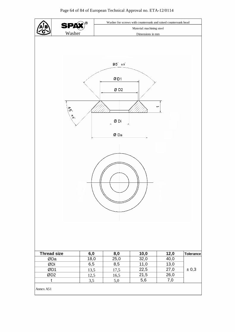
Page 64 of 84 of European Technical Approval no. ETA-12/0114
Annex A51
26,07,0
10,032,0
12,040,013,027,0
11,022,5
ØDi ØD1
3,5 5,6ØD2
t16,55,0
Washer for screws with countersunk and raised countersunk head
Material: machining steel
Dimensions in mm
21,5
6,513,512,5
6,018,0
± 0,3
Tolerance
Washer
Thread size ØDa
8,025,08,517,5
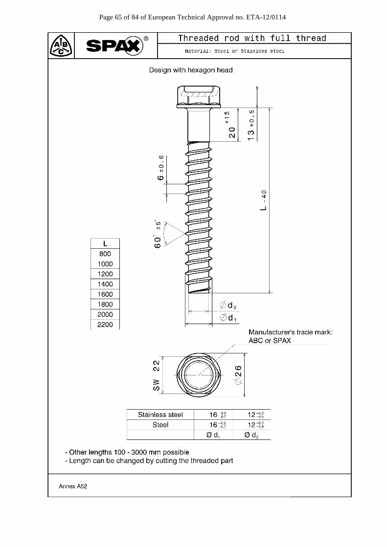
Page 65 of 84 of European Technical Approval no. ETA-12/0114
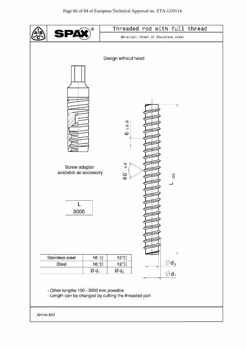
Page 66 of 84 of European Technical Approval no. ETA-12/0114

Page 67 of 84 of European Technical Approval no. ETA-12/0114
Annex B Minimum distances and spacing
Minimum distances and spacing for exclusively axially loaded SPAX screws with CUT or 4CUT drill tip or with d ≤ 8 mm in non-predrilled holes in members of solid timber, glued laminated timber or similar glued products Single configuration
a3,c
Top View
a4,c
a4,c
a2 s
s
Side Views
s
s
a4,c
a4,ca3,c
a1
a1
F
F
F
Tim
ber
thic
knes
sC
ompo
nen t
wid
th
α
> 1
2· d
grain direction screw axis S centroid of the part of the screw in the timber
15° < α < 90° a1 > 5 · d a2 > 2,5 · d a3,c > 5 · d a4,c > 4 · d > 3 · d for screws with CUT or 4CUT drill tip a1 · a2 > 25 · d²
Minimum distances and spacing see also 4.2 Minimum timber thickness t = 12 · d for solid or glued laminated timber and t = 6 · d for laminated veneer lumber, see also 4.2
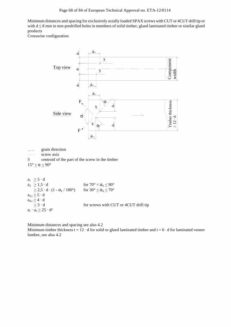
Page 68 of 84 of European Technical Approval no. ETA-12/0114
Minimum distances and spacing for exclusively axially loaded SPAX screws with CUT or 4CUT drill tip or with d ≤ 8 mm in non-predrilled holes in members of solid timber, glued laminated timber or similar glued products Crosswise configuration
Top view
Side view
a3,c
a3,c
a3,c
a3,c
a4,c
a4,c
a4, c
a4, c
a2 s
s
s
s αα
αk
F
F
Com
pone
ntw
idth
Tim
ber
thic
knes
s>
12
· d1
grain direction screw axis S centroid of the part of the screw in the timber
15° < α < 90° a1 > 5 · d a2 > 1,5 · d for 70° < αk < 90° > 2,5 · d · (1 - αk / 180°) for 30° < αk < 70° a3,c > 5 · d a4,c > 4 · d > 3 · d for screws with CUT or 4CUT drill tip a1 · a2 > 25 · d²
Minimum distances and spacing see also 4.2 Minimum timber thickness t = 12 · d for solid or glued laminated timber and t = 6 · d for laminated veneer lumber, see also 4.2
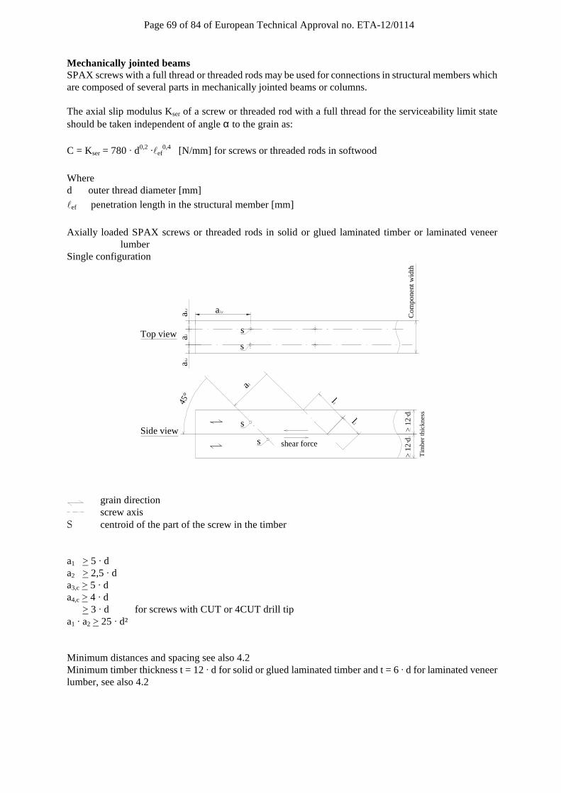
Page 69 of 84 of European Technical Approval no. ETA-12/0114
Mechanically jointed beams SPAX screws with a full thread or threaded rods may be used for connections in structural members which are composed of several parts in mechanically jointed beams or columns. The axial slip modulus Kser of a screw or threaded rod with a full thread for the serviceability limit state should be taken independent of angle α to the grain as:
C = Kser = 780 · d0,2 ·ℓef0,4 [N/mm] for screws or threaded rods in softwood
Where d outer thread diameter [mm]
ℓef penetration length in the structural member [mm]
Axially loaded SPAX screws or threaded rods in solid or glued laminated timber or laminated veneer
lumber Single configuration
Top view
Side views
s
a4,c
a4,c
a2
Com
pone
nt w
idth
Tim
ber
t hic
knes
s
shear force
45°
a1
l1
l 2
> 1
2·d1
>
12·
d1
a3,c
s
s
grain direction screw axis S centroid of the part of the screw in the timber
a1 > 5 · d a2 > 2,5 · d a3,c > 5 · d a4,c > 4 · d > 3 · d for screws with CUT or 4CUT drill tip a1 · a2 > 25 · d² Minimum distances and spacing see also 4.2 Minimum timber thickness t = 12 · d for solid or glued laminated timber and t = 6 · d for laminated veneer lumber, see also 4.2

Page 70 of 84 of European Technical Approval no. ETA-12/0114
Axially loaded SPAX screws or threaded rods in solid or glued laminated timber or laminated veneer lumber Crosswise configuration
shear force
s s
s s
> 1
2 · d
1
T
imbe
r th
ick n
ess
Co m
pone
nt
wid
t h
l1
l2
a4,c
a4,c
a2
a1
45°
Top view
Side view αk
> 1
2 · d
1
grain direction screw axis S centroid of the part of the screw in the timber
a1 > 5 · d a2 > 2,5 · d (a2 > 1,5 · d between the crossing screws of a screw couple) a3,c > 5 · d a4,c > 4 · d > 3 · d for screws with CUT or 4CUT drill tip a1 · a2 > 25 · d²
Minimum distances and spacing see also 4.2 Minimum timber thickness t = 12 · d for solid or glued laminated timber and t = 6 · d for laminated veneer lumber, see also 4.2
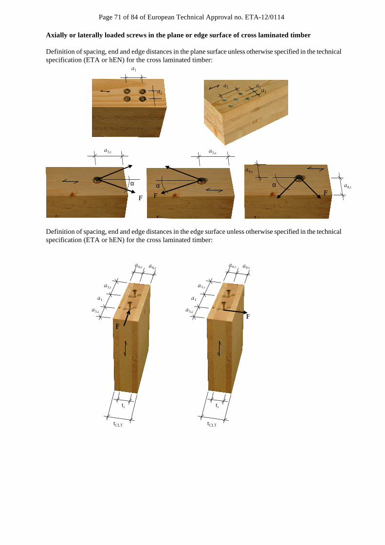
Page 71 of 84 of European Technical Approval no. ETA-12/0114
Axially or laterally loaded screws in the plane or edge surface of cross laminated timber Definition of spacing, end and edge distances in the plane surface unless otherwise specified in the technical specification (ETA or hEN) for the cross laminated timber:
Definition of spacing, end and edge distances in the edge surface unless otherwise specified in the technical specification (ETA or hEN) for the cross laminated timber:
F
α a4,t
a4,c
F
α
a3,c
α
F
a3,t
a1
a2 a2 a2
a1
tCLT
F
ti
a3,c
a1
a3,c
a4,c a4,t
tCLT
F
ti
a3,c
a1
a3,t
a4,c a4,c
F
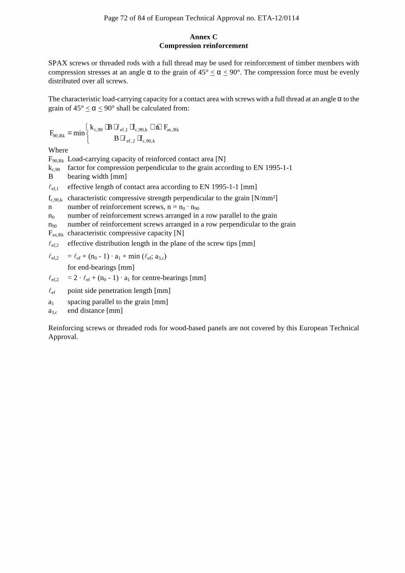
Page 72 of 84 of European Technical Approval no. ETA-12/0114
Annex C Compression reinforcement
SPAX screws or threaded rods with a full thread may be used for reinforcement of timber members with compression stresses at an angle α to the grain of 45° < α < 90°. The compression force must be evenly distributed over all screws. The characteristic load-carrying capacity for a contact area with screws with a full thread at an angle α to the grain of 45° < α < 90° shall be calculated from:
c,90 ef ,1 c,90,k ax,Rk90,Rk
ef ,2 c,90,k
k B f n FF min
B f
⋅ ⋅ ⋅ + ⋅= ⋅ ⋅
ℓ
ℓ
Where F90,Rk Load-carrying capacity of reinforced contact area [N] kc,90 factor for compression perpendicular to the grain according to EN 1995-1-1 B bearing width [mm]
ℓef,1 effective length of contact area according to EN 1995-1-1 [mm]
fc,90,k characteristic compressive strength perpendicular to the grain [N/mm²] n number of reinforcement screws, n = n0 · n90
n0 number of reinforcement screws arranged in a row parallel to the grain n90 number of reinforcement screws arranged in a row perpendicular to the grain
Fax,Rk characteristic compressive capacity [N]
ℓef,2 effective distribution length in the plane of the screw tips [mm]
ℓef,2 = ℓef + (n0 - 1) · a1 + min (ℓef; a3,c)
for end-bearings [mm]
ℓef,2 = 2 · ℓef + (n0 - 1) · a1 for centre-bearings [mm]
ℓef point side penetration length [mm]
a1 spacing parallel to the grain [mm] a3,c end distance [mm] Reinforcing screws or threaded rods for wood-based panels are not covered by this European Technical Approval.
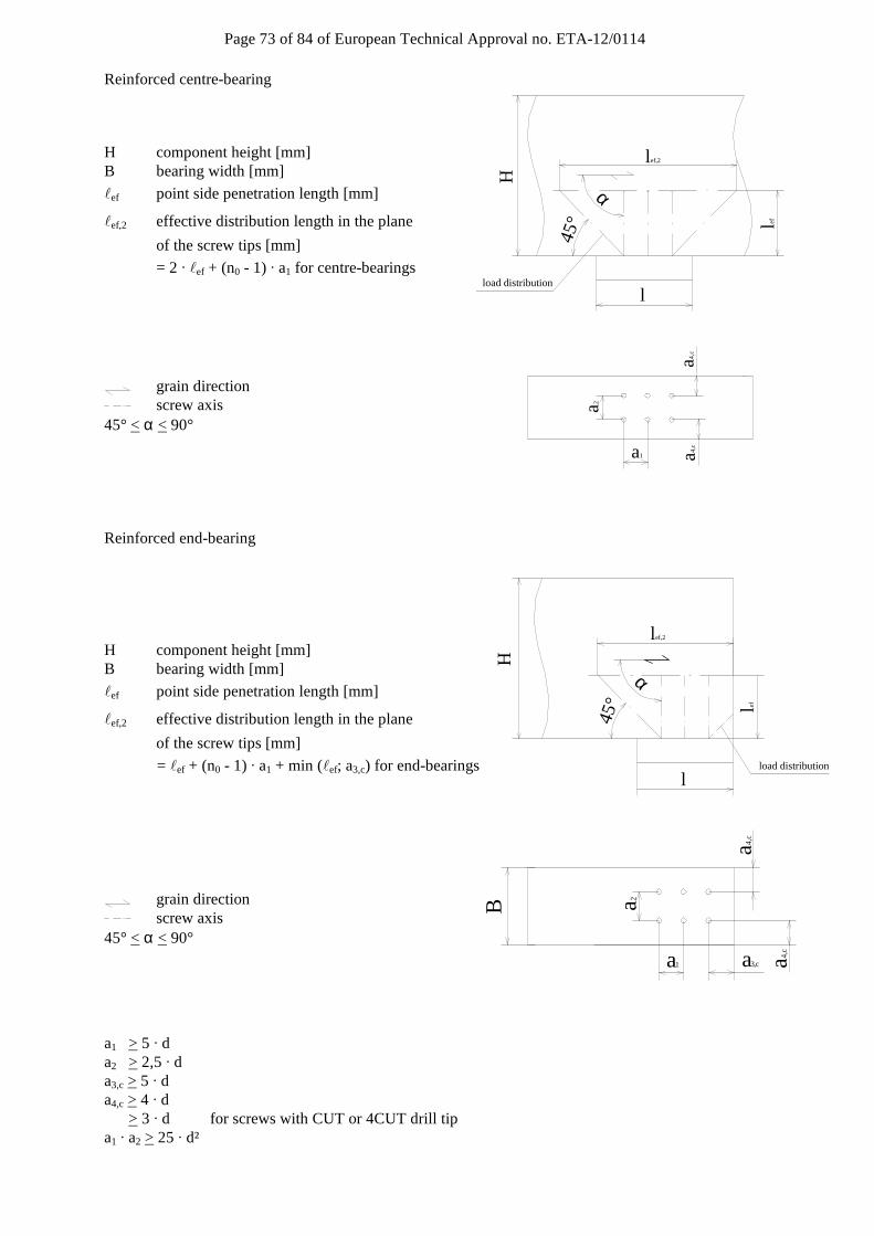
Page 73 of 84 of European Technical Approval no. ETA-12/0114
l ef,2
l
lef
load distribution
45°
H
α
lef,2
l
lefload distribution
45°
α
H
a2
a3,c a4,c
a1
a4,c
B
a2
a1
a4,c
a4,c
Reinforced centre-bearing
H component height [mm] B bearing width [mm]
ℓef point side penetration length [mm]
ℓef,2 effective distribution length in the plane
of the screw tips [mm]
= 2 · ℓef + (n0 - 1) · a1 for centre-bearings
grain direction screw axis 45° < α < 90°
Reinforced end-bearing
H component height [mm] B bearing width [mm]
ℓef point side penetration length [mm]
ℓef,2 effective distribution length in the plane
of the screw tips [mm]
= ℓef + (n0 - 1) · a1 + min (ℓef; a3,c) for end-bearings
grain direction screw axis 45° < α < 90° a1 > 5 · d a2 > 2,5 · d a3,c > 5 · d a4,c > 4 · d > 3 · d for screws with CUT or 4CUT drill tip a1 · a2 > 25 · d²

Page 74 of 84 of European Technical Approval no. ETA-12/0114
Annex D Tensile reinforcement perpendicular to grain
Unless specified otherwise in national provisions that apply at the installation site, the axial capacity of a reinforcement of a timber member loaded by a connection force perpendicular to the grain shall fulfil the following condition:
2 390,d
ax,Rd
1 3 2 F1
F
− ⋅α + ⋅ α ⋅ ≤
Where F90,d Design value of the force component perpendicular to the grain, α = a/h h = member depth Fax,Rd Minimum of the design values of the withdrawal capacity and the tensile capacity of the reinforcing
screws or threaded rods where ℓef is the smaller value of the penetration depth below or above the
potential crack
F90
h
lef,c
lef,t
a
potential crack
A
A
F90 F90/2F90/2
b
t t
ar
ah
h1 h2hi
hn
A
A
F90 F90/2F90/2
b
t t
ar
ah
h1 h2hi
hn
Unless specified otherwise in national provisions that apply at the installation site, the axial capacity of a reinforcement of a notched beam support shall fulfil the following condition:
( ) ( )2 3d
ax,Rd
1,3 V 3 1 2 11
F
⋅ ⋅ ⋅ − α − ⋅ − α ≤
Where Vd Design value of the shear force, α = he/h h = member depth Fax,Rd Minimum of the design values of the withdrawal capacity and the tensile capacity of the reinforcing
screws or threaded rods where ℓef is the smaller value of the penetration depth below or above the
potential crack
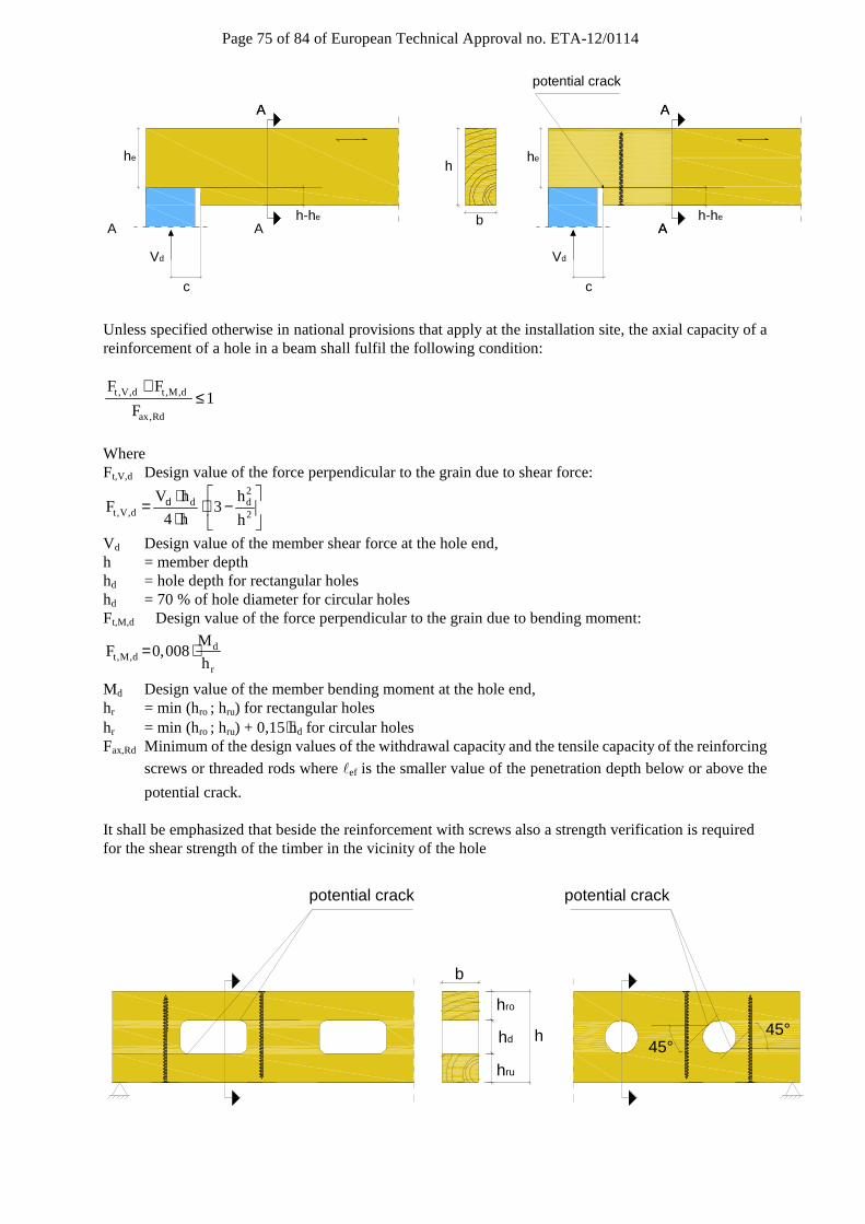
Page 75 of 84 of European Technical Approval no. ETA-12/0114
A
A
c
A
A
Vd
b
heh
h-he
A
A
A
A
Vd
he
h-he
c
potential crack
Unless specified otherwise in national provisions that apply at the installation site, the axial capacity of a reinforcement of a hole in a beam shall fulfil the following condition:
t ,V,d t,M,d
ax,Rd
F F1
F
+≤
Where Ft,V,d Design value of the force perpendicular to the grain due to shear force:
2d d
t,V,d 2
V h hF 3
4 h h
⋅= ⋅ − ⋅
d
Vd Design value of the member shear force at the hole end, h = member depth hd = hole depth for rectangular holes hd = 70 % of hole diameter for circular holes Ft,M,d Design value of the force perpendicular to the grain due to bending moment:
dt,M,d
r
MF 0,008
h= ⋅
Md Design value of the member bending moment at the hole end, hr = min (hro ; hru) for rectangular holes hr = min (hro ; hru) + 0,15⋅hd for circular holes Fax,Rd Minimum of the design values of the withdrawal capacity and the tensile capacity of the reinforcing
screws or threaded rods where ℓef is the smaller value of the penetration depth below or above the
potential crack. It shall be emphasized that beside the reinforcement with screws also a strength verification is required for the shear strength of the timber in the vicinity of the hole
h
hro
hd
hru
b
potential crackpotential crack
45°45°
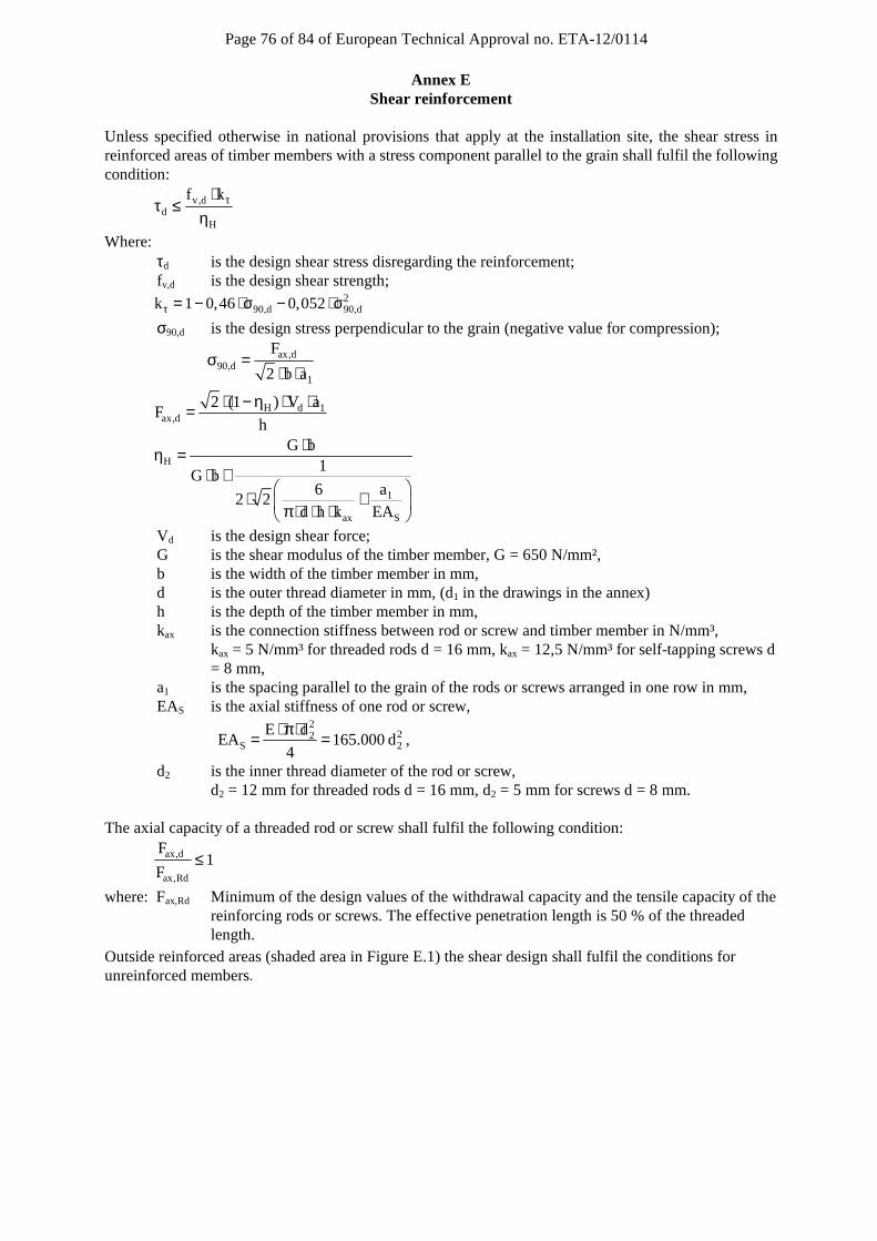
Page 76 of 84 of European Technical Approval no. ETA-12/0114
Annex E Shear reinforcement
Unless specified otherwise in national provisions that apply at the installation site, the shear stress in reinforced areas of timber members with a stress component parallel to the grain shall fulfil the following condition:
v,dd
H
f k τ⋅τ ≤
η
Where: τd is the design shear stress disregarding the reinforcement; fv,d is the design shear strength;
290,d 90,dk 1 0,46 0,052τ = − ⋅ σ − ⋅ σ
σ90,d is the design stress perpendicular to the grain (negative value for compression);
ax,d90,d
1
F
2 b aσ =
⋅ ⋅
H d 1ax,d
2 (1 ) V aF
h
⋅ − η ⋅ ⋅=
H
1
ax S
G b1
G b6 a
2 2d h k EA
⋅η =⋅ +
⋅ + π ⋅ ⋅ ⋅
Vd is the design shear force; G is the shear modulus of the timber member, G = 650 N/mm², b is the width of the timber member in mm, d is the outer thread diameter in mm, (d1 in the drawings in the annex) h is the depth of the timber member in mm, kax is the connection stiffness between rod or screw and timber member in N/mm³,
kax = 5 N/mm³ for threaded rods d = 16 mm, kax = 12,5 N/mm³ for self-tapping screws d = 8 mm,
a1 is the spacing parallel to the grain of the rods or screws arranged in one row in mm, EAS is the axial stiffness of one rod or screw,
2
22S 2
E dEA 165.000 d
4
⋅ π ⋅= = ,
d2 is the inner thread diameter of the rod or screw, d2 = 12 mm for threaded rods d = 16 mm, d2 = 5 mm for screws d = 8 mm.
The axial capacity of a threaded rod or screw shall fulfil the following condition:
ax,d
ax,Rd
F1
F≤
where: Fax,Rd Minimum of the design values of the withdrawal capacity and the tensile capacity of the reinforcing rods or screws. The effective penetration length is 50 % of the threaded length.
Outside reinforced areas (shaded area in Figure E.1) the shear design shall fulfil the conditions for unreinforced members.
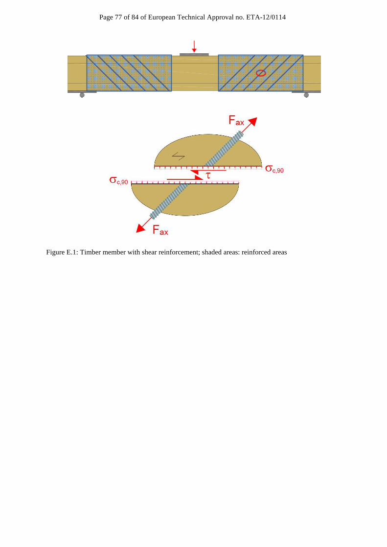
Page 77 of 84 of European Technical Approval no. ETA-12/0114
Figure E.1: Timber member with shear reinforcement; shaded areas: reinforced areas

Page 78 of 84 of European Technical Approval no. ETA-12/0114
Annex F Thermal insulation material on top of rafters
SPAX screws with an outer thread diameter 6 mm ≤ d ≤ 12 mm may be used for the fixing of Thermal insulation material on top of rafters. The thickness of the insulation shall not exceed 400 mm. The rafter insulation must be placed on top of solid timber or glued laminated timber rafters and be fixed by battens arranged parallel to the rafters or by wood-based panels on top of the insulation layer. The insulation of vertical facades is also covered by the rules given here. Screws must be screwed in the rafter through the battens or panels and the insulation without pre-drilling in one sequence. The angle α between the screw axis and the grain direction of the rafter should be between 30° and 90°. The rafter consists of solid timber (softwood) according to EN 14081-1, glued laminated timber according to EN 14080, cross-laminated timber, or laminated veneer lumber according to EN 14374 or to European Technical Approval or similar glued members according to European Technical Approval and has a minimum width of 60 mm. The battens must be from solid timber (softwood) according to EN 338:2003-04. The minimum thickness t and the minimum width b of the battens is given as follows: Screws d ≤ 8,0 mm: bmin = 50 mm tmin = 30 mm Screws d = 10 mm: bmin = 60 mm tmin = 40 mm Screws d = 12 mm: bmin = 80 mm tmin = 100 mm Alternatively to the battens, panels with a minimum thickness of 20 mm from plywood according to EN 636, particleboard according to EN 312, oriented strand board OSB/3 and OSB/4 according to EN 300 or European Technical Approval and solid wood panels according to EN 13353 may be used. This only applies to the system with parallel inclined screws. The insulation must comply with a European Technical Approval. Friction forces shall not be considered for the design of the characteristic axial capacity of the screws. The anchorage of wind suction forces as well as the bending stresses of the battens or the boards, respectively, shall be considered in design. Additional screws perpendicular to the grain of the rafter (angle α = 90°) may be arranged if necessary. The maximum screw spacing is eS = 1,75 m.

Page 79 of 84 of European Technical Approval no. ETA-12/0114
Thermal insulation material on rafters with parallel inclined screws Mechanical model
The system of rafter, Thermal insulation material on top of rafter and battens parallel to the rafter may be considered as a beam on elastic foundation. The batten represents the beam, and the Thermal insulation material on top of the rafter the elastic foundation. The minimum compression stress of the Thermal insulation material at 10 % deformation, measured according to EN 8262, shall be σ(10 %) = 0,05 N/mm². The batten is loaded perpendicular to the axis by point loads Fb. Further point loads Fs are from the shear load of the roof due to dead and snow load, which are transferred from the screw heads into the battens.
ß
e scr
e scr
e scr
ß
batten
heat insulation
vapor barrierroof boarding
rafter
dead load and snow load s0
wind
wpressure
wsuction
axisbatten
top edge rafter
compression in heat insulation
screw axistensile force Fz
concentrated compression load in heat insulation
α = angle between screw axis and rafter axisβ = roof pitchescr = screws distanceℓef = penetration length in the rafter
α
ℓef
α
2 EN 826:1996 Thermal insulating products for building applications - Determination of compression
behaviour
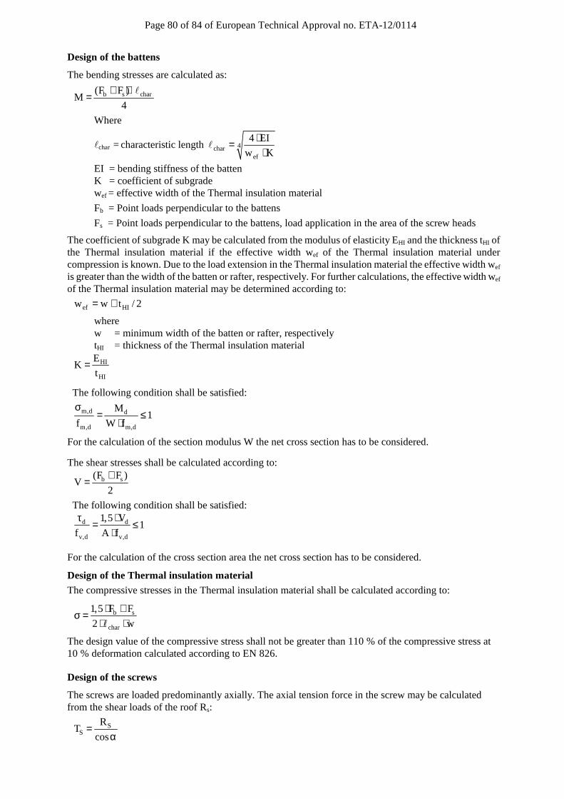
Page 80 of 84 of European Technical Approval no. ETA-12/0114
Design of the battens
The bending stresses are calculated as:
b s char(F F )M
4
+ ⋅=
ℓ
Where
ℓchar = characteristic length 4charef
4 EI
w K
⋅=⋅
ℓ
EI = bending stiffness of the batten K = coefficient of subgrade wef = effective width of the Thermal insulation material
Fb = Point loads perpendicular to the battens
Fs = Point loads perpendicular to the battens, load application in the area of the screw heads
The coefficient of subgrade K may be calculated from the modulus of elasticity EHI and the thickness tHI of the Thermal insulation material if the effective width wef of the Thermal insulation material under compression is known. Due to the load extension in the Thermal insulation material the effective width wef is greater than the width of the batten or rafter, respectively. For further calculations, the effective width wef of the Thermal insulation material may be determined according to:
ef HIw w t / 2= +
where w = minimum width of the batten or rafter, respectively tHI = thickness of the Thermal insulation material
HI
HI
EK
t=
The following condition shall be satisfied:
m,d d
m,d m,d
M1
f W f
σ= ≤
⋅
For the calculation of the section modulus W the net cross section has to be considered.
The shear stresses shall be calculated according to:
b s(F F )V
2
+=
The following condition shall be satisfied:
d d
v,d v,d
1,5 V1
f A f
τ ⋅= ≤
⋅
For the calculation of the cross section area the net cross section has to be considered.
Design of the Thermal insulation material
The compressive stresses in the Thermal insulation material shall be calculated according to:
b s
char
1,5 F F
2 w
⋅ +σ =
⋅ ⋅ℓ
The design value of the compressive stress shall not be greater than 110 % of the compressive stress at 10 % deformation calculated according to EN 826.
Design of the screws
The screws are loaded predominantly axially. The axial tension force in the screw may be calculated from the shear loads of the roof Rs:
SS
RT
cos=
α
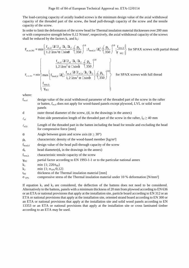
Page 81 of 84 of European Technical Approval no. ETA-12/0114
The load-carrying capacity of axially loaded screws is the minimum design value of the axial withdrawal capacity of the threaded part of the screw, the head pull-through capacity of the screw and the tensile capacity of the screw.
In order to limit the deformation of the screw head for Thermal insulation material thicknesses over 200 mm or with compressive strength below 0,12 N/mm², respectively, the axial withdrawal capacity of the screws shall be reduced by the factors k1 and k2:
0.8 0.8ax,d ef 1 2 tens,k2k k
ax, ,Rd head,d hM2
f d k k fF min ;f d ;
1.2 cos² sin ² 350 350α
⋅ ⋅ ⋅ ⋅ ρ ρ = ⋅ ⋅ ⋅ ⋅ α + α γ
ℓfor SPAX screws with partial thread
ax , ,Rd
0,8ax,d ef 1 2 k
2 2
0,8ax,d ef ,b 1 22 k
head,d h 2 2
tens,k
M2
F min
f d k k
3501,2 cos sin
f d k kmax f d ;
3501,2 cos sin
f
α =
⋅ ⋅ ⋅ ⋅ ρ ⋅ ⋅ α + α ⋅ ⋅ ⋅ ⋅ ρ ⋅ ⋅ ⋅ α + α γ
ℓ
ℓ for SPAX screws with full thread
where: fax,d design value of the axial withdrawal parameter of the threaded part of the screw in the rafter
or batten, fax,d does not apply for wood-based panels except plywood, LVL or solid wood panels
d outer thread diameter of the screw, (d1 in the drawings in the annex)
ℓef Point side penetration length of the threaded part of the screw in the rafter, lef ≥ 40 mm
ℓef,b Length of the threaded part in the batten including the head for tensile and excluding the head for compressive force [mm]
α Angle between grain and screw axis (α > 30°)
ρk characteristic density of the wood-based member [kg/m³]
fhead,d design value of the head pull-through capacity of the screw
dh head diameter(dk in the drawings in the annex)
f tens,k characteristic tensile capacity of the screw
γM2 partial factor according to EN 1993-1-1 or to the particular national annex
k1 min {1; 220/tHI} k2 min {1; σ10%/0,12} tHI thickness of the Thermal insulation material [mm] σ 10% compressive stress of the Thermal insulation material under 10 % deformation [N/mm²] If equation k1 and k2 are considered, the deflection of the battens does not need to be considered. Alternatively to the battens, panels with a minimum thickness of 20 mm from plywood according to EN 636 or an ETA or national provisions that apply at the installation site, particle board according to EN 312 or an ETA or national provisions that apply at the installation site, oriented strand board according to EN 300 or an ETA or national provisions that apply at the installation site and solid wood panels according to EN 13353 or an ETA or national provisions that apply at the installation site or cross laminated timber according to an ETA may be used.
Page 82 of 84 of European Technical Approval no. ETA-12/0114
Thermal insulation material on rafters with alternatively inclined screws
Mechanical model
Depending on the screw spacing and the arrangement of tensile and compressive screws with different inclinations the battens are loaded by significant bending moments. The bending moments are derived based on the following assumptions: • The tensile and compressive loads in the screws are determined based on equilibrium conditions
from the actions parallel and perpendicular to the roof plane. These actions are constant line loads q⊥ and q .
• The screws act as hinged columns supported 10 mm within the batten or rafter, respectively. The effective column length consequently equals the length of the screw between batten and rafter plus 20 mm.
• The batten is considered as a continuous beam with a constant span ℓ = A + B.
The compressive screws constitute the supports of the continuous beam while the tensile screws transfer concentrated loads perpendicular to the batten axis.
The screws are predominantly loaded in withdrawal or compression, respectively. The screw’s normal forces are determined based on the loads parallel and perpendicular to the roof plane:
Compressive screw: II 2c,Ed
1 1 2 1 2
q q sin(90 )F (A B)
cos sin / tan sin( )⊥ ⋅ ° − α= + ⋅ − − α + α α α + α
Tensile screw: II 1t,Ed
2 2 1 1 2
q q sin(90 )F (A B)
cos sin / tan sin( )⊥ ⋅ ° − α= + ⋅ − α + α α α + α
Counter batten
90° - α1 = 0° to 60°
90° - α2 = 0° to 60°
1 Counter batten 2 Insulation 3 Vapour barrier 4 Sheathing 5 Compressive screw 6 Rafter
ℓef,b
ℓef,r
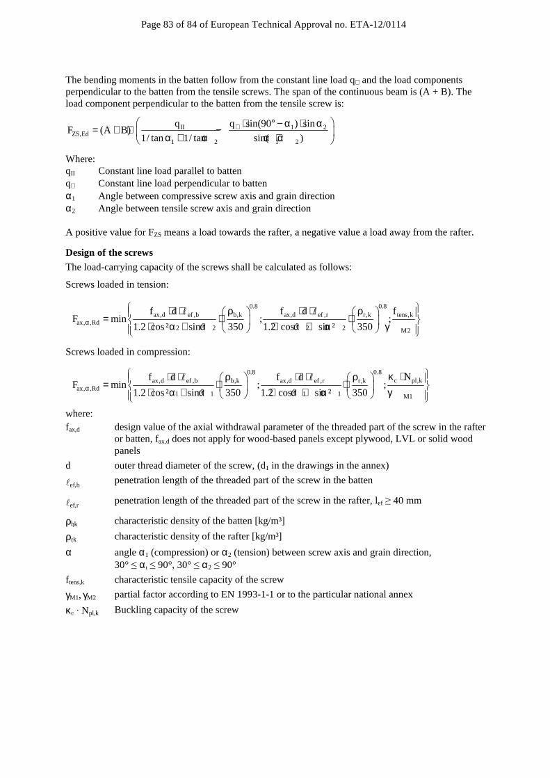
Page 83 of 84 of European Technical Approval no. ETA-12/0114
The bending moments in the batten follow from the constant line load q⊥ and the load components perpendicular to the batten from the tensile screws. The span of the continuous beam is (A + B). The load component perpendicular to the batten from the tensile screw is:
II 1 2ZS,Ed
1 2 1 2
q q sin(90 ) sinF (A B)
1/ tan 1/ tan sin( )⊥ ⋅ ° − α ⋅ α= + ⋅ − α + α α + α
Where: qII Constant line load parallel to batten q⊥ Constant line load perpendicular to batten α1 Angle between compressive screw axis and grain direction α2 Angle between tensile screw axis and grain direction A positive value for FZS means a load towards the rafter, a negative value a load away from the rafter.
Design of the screws
The load-carrying capacity of the screws shall be calculated as follows:
Screws loaded in tension:
0.8 0.8ax,d ef ,b b,k ax,d ef ,r r,k tens,k
ax, ,Rd2 2 2 2 M2
f d f d fF min ; ;
1.2 cos² sin ² 350 1.2 cos ² sin ² 350α
⋅ ⋅ ρ ⋅ ⋅ ρ = ⋅ ⋅ ⋅ α + α ⋅ α + α γ
ℓ ℓ
Screws loaded in compression:
0.8 0.8c pl,kax,d ef ,b b,k ax,d ef ,r r,k
ax, ,Rd1 1 1 1 M1
Nf d f dF min ; ;
1.2 cos² sin ² 350 1.2 cos² sin ² 350α
κ ⋅⋅ ⋅ ρ ⋅ ⋅ ρ = ⋅ ⋅ ⋅ α + α ⋅ α + α γ
ℓ ℓ
where: fax,d design value of the axial withdrawal parameter of the threaded part of the screw in the rafter
or batten, fax,d does not apply for wood-based panels except plywood, LVL or solid wood panels
d outer thread diameter of the screw, (d1 in the drawings in the annex)
ℓef,b penetration length of the threaded part of the screw in the batten
ℓef,r penetration length of the threaded part of the screw in the rafter, lef ≥ 40 mm
ρbk characteristic density of the batten [kg/m³]
ρrk characteristic density of the rafter [kg/m³]
α angle α1 (compression) or α2 (tension) between screw axis and grain direction, 30° ≤ α ≤ 90°, 30° ≤ α2 ≤ 90°
f tens,k characteristic tensile capacity of the screw
γM1, γM2 partial factor according to EN 1993-1-1 or to the particular national annex
κc · Npl,k Buckling capacity of the screw

Page 84 of 84 of European Technical Approval no. ETA-12/0114
Free screw length [mm]
Carbon steel Stainless steel 6,0 mm 8,0 mm 10,0 mm 12,0 mm 10,0 mm 12,0 mm
κc · Npl,k [kN] κc · Npl,k [kN] κc · Npl,k [kN] κc · Npl,k [kN] κc · Npl,k [kN] κc · Npl,k [kN]
≤ 100 1,12 2,79 6,09 12,0 5,22 9,68 120 0,85 2,12 4,68 9,39 4,16 7,97 140 0,66 1,66 3,70 7,50 3,36 6,58 160 0,53 1,34 2,99 6,10 2,76 5,48 180 0,43 1,10 2,48 5,06 2,30 4,62 200 0,92 2,07 4,26 1,94 3,93 220 0,78 1,76 3,65 1,66 3,38 240 0,67 1,51 3,14 1,44 2,94 260 0,58 1,32 2,73 1,26 2,58 280 0,51 1,15 2,40 1,11 2,28 300 0,45 1,02 2,13 0,98 2,02 320 0,40 0,91 1,90 0,88 1,82 340 0,36 0,82 1,70 0,79 1,63 360 0,32 0,73 1,53 0,71 1,48 380 0,29 0,67 1,39 0,65 1,34 400 0,26 0,61 1,27 0,59 1,22 420 0,24 0,55 1,16 0,54 1,12 440 0,22 0,51 1,06 0,49 1,03 460 0,20 0,47 0,98 0,46 0,95 480 0,19 0,43 0,91 0,42 0,88