Embed Size (px)
Citation preview

Centre Scientifique et
Technique du Bâtiment 84 avenue Jean Jaurès CHAMPS-SUR-MARNE F-77447 Marne-la-Vallée Cedex 2 Tél. : (33) 01 64 68 82 82 Fax : (33) 01 60 05 70 37
Member of
www.eota.eu
European Technical Assessment
ETA- 15/0810 of 13/02/2017
English translation prepared by CSTB - Original version in French language
General Part
Nom commercial Trade name
PoSB-PRO Power Screwbolt
Famille de produit Product family
Vis à béton pour usage multiple et pour applications non structurelles dans le béton
Concrete screw for multiple use and for non-structural applications in concrete
Titulaire Manufacturer
DEWALT/ Powers Richard-Klinger-Straße 11 65510 Idstein Germany
Usine de fabrication Manufacturing plants
Plant 5
Cette evaluation contient: This Assessment contains
13 pages incluant 10 annexes qui font partie intégrante de cette évaluation 13 pages including 10 annexes which form an integral part of this assessment
Base de l‘ETE Basis of ETA
ETAG 001, Partie 6 révisée January 2011, utilisée en tant que EAD
ETAG 001, Part 6 ammended January 2011 used as EAD
Cette evaluation remplace: This Assessment replaces
ETA- 15/0810 du 31/08/2016 ETA- 15/0810 of 31/08/2016
Translations of this European Technical Assessment in other languages shall fully correspond to the original issued document and should be identified as such. Communication of this European Technical Assessment, including transmission by electronic means, shall be in full. However, partial reproduction may be made, with the written consent of the issuing Technical Assessment Body. Any partial reproduction has to be identified as such.

European technical assessment ETA- 15/0810
English translation prepared by CSTB
Page 2 of 13| 13/02/2017
Specific Part
1 Technical description of the product
The Power Screwbolt is an anchor made of zinc plated steel or mechanicaly galvanized steel of size 6 mm. The anchor is screwed into a predrilled cylindrical drill hole. The special thread of the anchor cuts an internal thread into the member while setting. The anchorage is characterised by mechanical interlock in the special thread. The illustration and the description of the product are given in Annexes A.
2 Specification of the intended use
The performances given in Section 3 are only valid if the anchor is used in compliance with the specifications and conditions given in Annexes B.
The provisions made in this European technical assessment are based on an assumed working life of the anchor of 50 years. The indications given on the working life cannot be interpreted as a guarantee given by the producer, but are to be regarded only as a means for choosing the right products in relation to the expected economically reasonable working life of the works.
3 Performance of the product
3.1 Mechanical resistance and stability (BWR 1)
The essential characteristics regarding mechanical resistance and stability are included under the Basic Works Requirement Safety in use.
3.2 Safety in case of fire (BWR 2)
Essential characteristic Performance
Reaction to fire Anchorages satisfy requirements for Class A1
Resistance under fire See Annex C 2
3.3 Hygiene, health and the environment (BWR 3)
Regarding dangerous substances contained in this European technical approval, there may be requirements applicable to the products falling within its scope (e.g. transposed European legislation and national laws, regulations and administrative provisions). In order to meet the provisions of the Construction Products Directive, these requirements need also to be complied with, when and where they apply.
3.4 Safety in use (BWR 4)
Essential characteristic Performance
Characterisitic values for resistance for static and quasi static loads
See Annex C 1
3.5 Protection against noise (BWR 5)
Not relevant.
3.6 Energy economy and heat retention (BWR 6)
Not relevant.
3.7 Sustainable use of natural resources ( (BWR 7)
For the sustainable use of natural resources no performance was determined for this product.
3.8 General aspects relating to fitness for use
Durability and Serviceability are only ensured if the specifications of intended use according to Annex B 1 are kept.

European technical assessment ETA- 15/0810
English translation prepared by CSTB
Page 3 of 13| 13/02/2017
4 Assessment and verification of constancy of performance (AVCP)
According to Decision of the Commission of 17 February 1997 (97/161/EC) (OJ L 062 of 04.03.97 p. 41-42), the system of assessment and verification of constancy of performance (see Annex V and Article 65 Paragraph 2 to Regulation (EU) No 305/2011) given in the following table applies.
Product Intended use Level or class
System
Metal anchors for use in concrete
For use in redundant systems for
fixing and/or supporting to concrete
elements such as lightweight
suspended ceilings, as well as
installations
― 2+
5 Technical details necessary for the implementation of the AVCP system
Technical details necessary for the implementation of the Assessment and verification of constancy of performance (AVCP) system are laid down in the control plan deposited at Centre Scientifique et Technique du Bâtiment.
The manufacturer shall, on the basis of a contract, involve a notified body approved in the field of anchors for issuing the certificate of conformity CE based on the control plan.
The original French version is signed by
Charles Baloche
Technical Director

European technical assessment ETA- 15/0810
English translation prepared by CSTB
Page 4 of 13| 13/02/2017
PoSB-PRO Power Screwbolt
Product description
Installation condition
Annex A1
PoSB-PRO Power Screwbolt
Product in installed condition in concrete
Product and installed condition in precast pre‐stressed hollow core slabs
Core distance alvéoles lc ≥ 100 mm
Prestressing steel distance lp ≥ 100 mm
distance between anchor position
and prestressing steel ap ≥ 50 mm

European technical assessment ETA- 15/0810
English translation prepared by CSTB
Page 5 of 13| 13/02/2017
PoSB-PRO Power Screwbolt
Product descripion
Material
Annex A2
Head Marking:
Marking D X L where
D= Nominal diameter of the bore hole [mm]
L= Length of anchor [mm]
Table 1: Materials
Version Material Protection
PoSB-PRO
C-Steel Version C-Steel fuk≥ 700N/mm² Zinc plated > 5 m
PoSB-PRO MG
Mechanically galv. Version C-Steel fuk≥ 700N/mm²
Mechanically galvanized >
50 m

European technical assessment ETA- 15/0810
English translation prepared by CSTB
Page 6 of 13| 13/02/2017
PoSB-PRO Power Screwbolt
Product descripion
Material
Annex A3
Table 2: Different head styles
Drawing Denomination Abreviation Diameters
Hex Head Version PoSB-PRO HH 6
Pan Head Version PoSB-PRO Pan 6
Countersunk Version PoSB-PRO CSK 6
Hanger Version
Step thread M8/ M10
PoSB-PRO Hanger M8/ M10
6
Dome Head Version PoSB-PRO Dome 6

European technical assessment ETA- 15/0810
English translation prepared by CSTB
Page 7 of 13| 13/02/2017
PoSB-PRO Power Screwbolt
Intended Use
Specifications
Annex B1
Anchorages subject to:
Static, quasi-static loads
Fire exposure
Base materials:
Cracked concrete and non-cracked concrete.
Reinforced or unreinforced normal weight concrete of strength classes C 20/25 at least to C50/60 at most according to EN 206-1: 2013.
Precast, prestressed hollow concrete slabs with w/e ≤ 4,2 and strength classes C30/37 to C50/60.
Use conditions (Environmental conditions):
Structures subject to dry internal conditions.
Design:
The anchorages are designed under the responsibility of an engineer experienced in anchorages and concrete work.
The anchorages are designed under consideration of Technical Report TR055 in accordance with: - Method C of ETAG001 Annex C “Design Method for Anchorages” or - CEN/TS 1992-4:2009, Design method C1).
For application with resistance under fire exposure the anchorages are designed under consideration of Technical Report TR055 in accordance with method given in:
- TR020 “Evaluation of Anchorage in Concrete concerning Resistance to Fire” or - CEN/TS 1992-4-1:2009, Annex D1).
Verifiable calculation notes and drawings are prepared taking account of the loads to be anchored. The position of the anchor is indicated on the design drawings.
The anchor may only be used if in the design and installation specifications for the fixture the excessive slip or failure of one anchor will not result in a significantly violation of the requirements on the fixture in the serviceability and ultimate state
The anchor is to be used only for multiple use for non-structural applications, the definition of multiple use according to the Member States is given in the informative Annex 1 of ETAG 001, Part 6.
Installation:
Anchor installation carried out by appropriately qualified personnel and under the supervision of the person responsible for technical matters of the site.
Use of the anchor only as supplied by the manufacturer without exchanging the components of an anchor.
Anchor installation in accordance with the manufacturer’s specifications and drawings and using the appropriate tools.
Effective anchorage depth, edge distances and spacing not less than the specified values without minus tolerances.
Hole drilling by hammer drill.
Cleaning of the hole of drilling dust.
In case of aborted hole, drilling of new hole at a minimum distance of twice the depth of the aborted hole, or smaller distance provided the aborted drill hole is filled with high strength mortar and no shear or oblique tension loads in the direction of aborted hole.
The anchor is suited for installation with a torque wrench by hand and for installation with a suitable impact screw driver.
Nota 1: The CEN/TS 1992-4-1:2009 standard is going to be replaced by EN 1992-4
European technical assessment ETA- 15/0810
English translation prepared by CSTB
Page 8 of 13| 13/02/2017
PoSB-PRO Power Screwbolt
Intended Use
Installation parameters
Annex B2
.
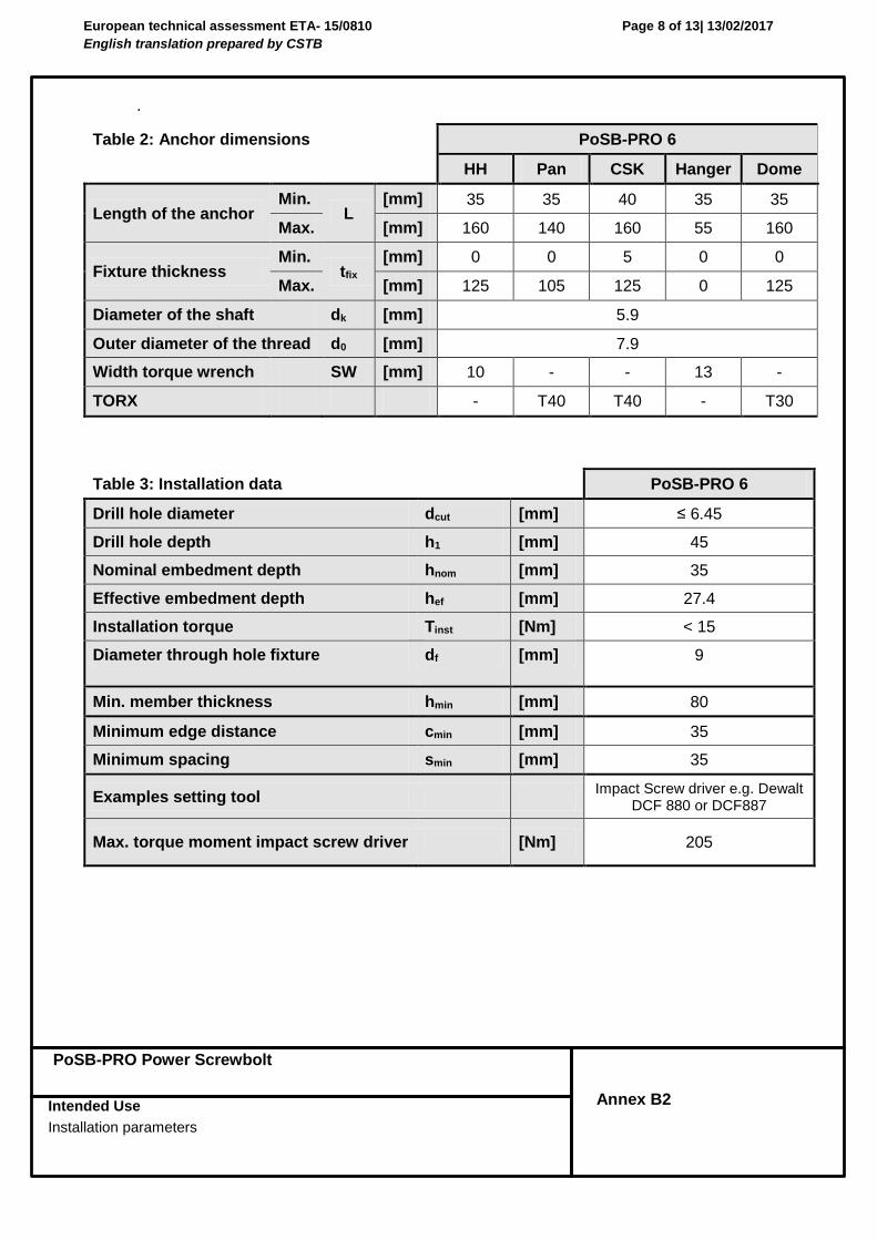
Table 2: Anchor dimensions PoSB-PRO 6
HH Pan CSK Hanger Dome
Length of the anchor Min.
L [mm] 35 35 40 35 35
Max. [mm] 160 140 160 55 160
Fixture thickness Min.
tfix [mm] 0 0 5 0 0
Max. [mm] 125 105 125 0 125
Diameter of the shaft dk [mm] 5.9
Outer diameter of the thread d0 [mm] 7.9
Width torque wrench SW [mm] 10 - - 13 -
TORX - T40 T40 - T30
Table 3: Installation data PoSB-PRO 6
Drill hole diameter dcut [mm] ≤ 6.45
Drill hole depth h1 [mm] 45
Nominal embedment depth hnom [mm] 35
Effective embedment depth hef [mm] 27.4
Installation torque Tinst [Nm] < 15
Diameter through hole fixture df [mm] 9
Min. member thickness hmin [mm] 80
Minimum edge distance cmin [mm] 35
Minimum spacing smin [mm] 35
Examples setting tool Impact Screw driver e.g. Dewalt
DCF 880 or DCF887
Max. torque moment impact screw driver [Nm] 205

European technical assessment ETA- 15/0810
English translation prepared by CSTB
Page 9 of 13| 13/02/2017
PoSB-PRO Power Screwbolt
Intended Use
Installation instructions
Annex B3
Installation instructions: Hex Head Version/ Dome head version/ Pan Head Version/ Countersunk Version
Installation instructions: Hanger Version

European technical assessment ETA- 15/0810
English translation prepared by CSTB
Page 10 of 13| 13/02/2017
PoSB-PRO Power Screwbolt
Intended Use
Installation instructions
Annex B4
Installation instructions: Hex Head Version/ Dome head version/ Pan Head Version/
Countersunk Version in precast pre‐stressed hollow core slabs

European technical assessment ETA- 15/0810
English translation prepared by CSTB
Page 11 of 13| 13/02/2017
PoSB-PRO Power Screwbolt
Intended Use
Installation instructions
Annex B5
Minimum spacing and edge distance of anchors and distance between
anchor groups in precast pre‐stressed hollow core slabs
Minimum edge distance cmin ≥ 100mm Minimum anchor spacing smin ≥ 100mm Minimum distance between anchor groups amin ≥ 100mm c1, c2 edge distance s1, s2 anchor spacing a1, a2 distance between anchor groups

European technical assessment ETA- 15/0810
English translation prepared by CSTB
Page 12 of 13| 13/02/2017
PoSB-PRO Concrete Screwbolt
Characteristic resistance for static and quasi static loads
Annex C1
Table 4: Characteristic resistance for static and quasi static loads
Anchor size 6
Type HH Pan CSK Hanger Dome
Nominal anchorage depth hnom ≥ [mm] 35
All load directions
Characteristic resistance in C20/25 to C50/60
FRk [kN] 3,5
Installation safety factor 2
1)=
inst
2) [-] 2,1
Design resistance in C20/25 to C50/60
FRd [kN] 1,66
Effective anchorage depth hef [mm] 27,4
Characteristic edge distance
ccr [mm] 200
Characteristic spacing scr [mm] 100
Shear load with lever arm
Characteristic bending resistance
M0Rk,s [N.m] 13,3
Table 5: Characteristic values for static and quasi‐static loads in precast pre‐stressed hollow core slabs C30/37 to C50/60
Anchor size 6
Type HH, Pan, CSK, Hanger, Dome
All load directions
Bottom flange thickness [mm] ≥ 35 ≥ 25
Characteristic resistance in C30/37 to C50/60
FRk [kN] 2,5 0,5
Installation safety factor 2
1)=
inst
2) [-] 2,1 2,1
Design resistance in C30/37 to C50/60
FRd [kN] 1,19 0.24
1) Parameter for design according to EOTA Annex C. 2) Parameter for design according to CEN/TS 1992-4-4:2009.

European technical assessment ETA- 15/0810
English translation prepared by CSTB
Page 13 of 13| 13/02/2017
PoSB-PRO Concrete Screwbolt
Characteristic resistance under fire exposure acc. to TR020
Annex C2
Table 6: Characteristic resistance under fire exposure for design according to TR020
Anchor size 6
Type HH Pan CSK Hanger Dome
Nominal anchorage depth
[mm] hnom ≥ 35
All load directions
Characteristic resistance
FRk,fi [kN]
R30 0,27
R60 0,24
R90 0,19
R120 0,13
Characteristic bending resistance
MRk,fi [N.m]
R30 0,24
R60 0,21
R90 0,17
R120 0,12
Edge distance R30…R120 [mm] ccr,fi 200
Fastener spacing R30…R120 [mm] scr,fi 100
The fire resistance data is only valid for concrete C20/25 to C50/60 with a minimun slab thickness of 80mm.
The edge distance of the fastener must be c ≥ 300 mm and ≥ 2hef if the fire attack is from more than one side.
The anchorage depth has to be increased for wet concrete by at least 30 mm compare to the given value.


![Agrément Technique Européen ETA-12/0020webapp.cstb.fr/agrement-technique-europeen/pdf/Doc_ETA...[W/m/K] selon EN 13163 ... L‘épaisseur du voile béton varie de 120 à 300 mm](https://img.pdfslide.net/doc/110x75/5d40f0d788c99377448d6771/agrement-technique-europeen-eta-12-wmk-selon-en-13163-lepaisseur-du.jpg)