Embed Size (px)
Citation preview
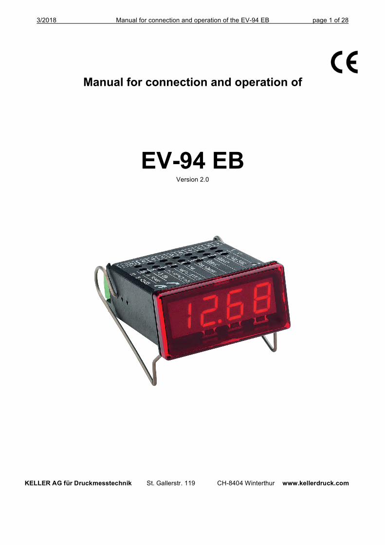
3/2018 Manual for connection and operation of the EV-94 EB page 1 of 28
Manual for connection and operation of
EV-94 EB Version 2.0
KELLER AG für Druckmesstechnik St. Gallerstr. 119 CH-8404 Winterthur www.kellerdruck.com
3/2018 Manual for connection and operation of the EV-94 EB page 2 of 28
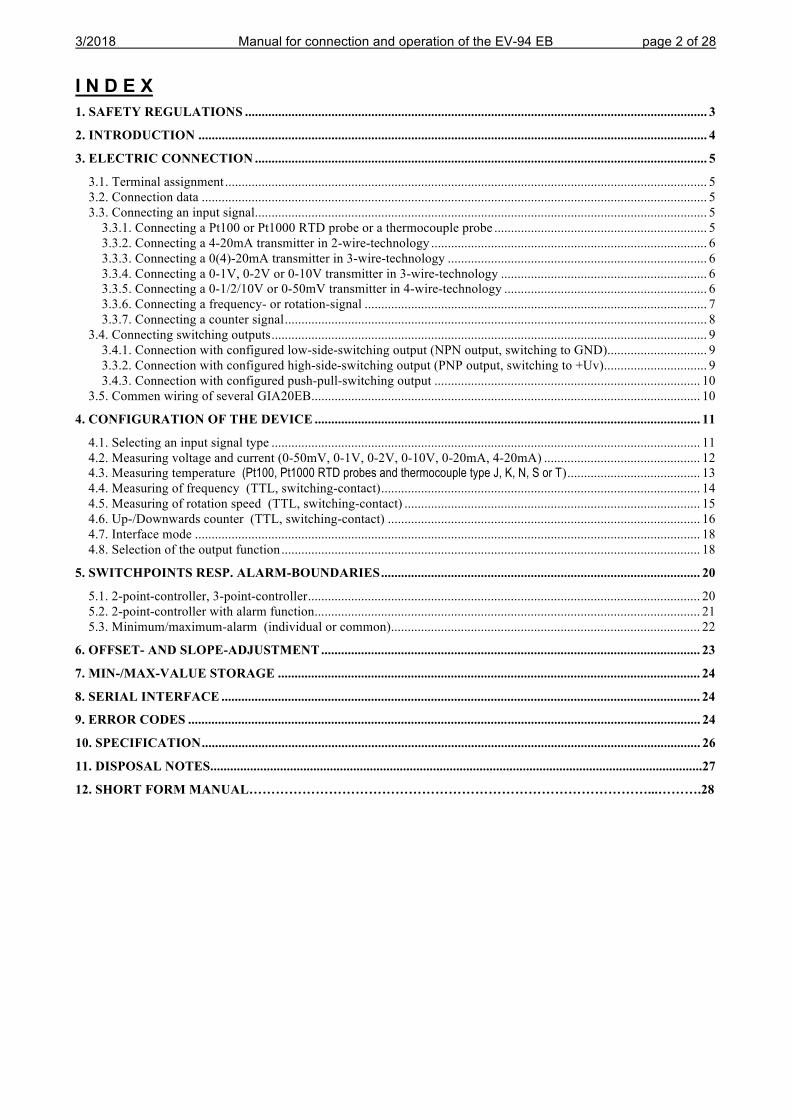
I N D E X 1. SAFETY REGULATIONS ........................................................................................................................................... 3
2. INTRODUCTION ......................................................................................................................................................... 4
3. ELECTRIC CONNECTION ........................................................................................................................................ 5
3.1. Terminal assignment ................................................................................................................................................. 5 3.2. Connection data ........................................................................................................................................................ 5 3.3. Connecting an input signal ........................................................................................................................................ 5
3.3.1. Connecting a Pt100 or Pt1000 RTD probe or a thermocouple probe ................................................................ 5 3.3.2. Connecting a 4-20mA transmitter in 2-wire-technology ................................................................................... 6 3.3.3. Connecting a 0(4)-20mA transmitter in 3-wire-technology .............................................................................. 6 3.3.4. Connecting a 0-1V, 0-2V or 0-10V transmitter in 3-wire-technology .............................................................. 6 3.3.5. Connecting a 0-1/2/10V or 0-50mV transmitter in 4-wire-technology ............................................................. 6 3.3.6. Connecting a frequency- or rotation-signal ....................................................................................................... 7 3.3.7. Connecting a counter signal ............................................................................................................................... 8
3.4. Connecting switching outputs ................................................................................................................................... 9 3.4.1. Connection with configured low-side-switching output (NPN output, switching to GND) .............................. 9 3.3.2. Connection with configured high-side-switching output (PNP output, switching to +Uv) ............................... 9 3.4.3. Connection with configured push-pull-switching output ................................................................................ 10
3.5. Commen wiring of several GIA20EB ..................................................................................................................... 10
4. CONFIGURATION OF THE DEVICE .................................................................................................................... 11
4.1. Selecting an input signal type ................................................................................................................................. 11 4.2. Measuring voltage and current (0-50mV, 0-1V, 0-2V, 0-10V, 0-20mA, 4-20mA) ............................................... 12 4.3. Measuring temperature (Pt100, Pt1000 RTD probes and thermocouple type J, K, N, S or T) ........................................ 13 4.4. Measuring of frequency (TTL, switching-contact) ................................................................................................ 14 4.5. Measuring of rotation speed (TTL, switching-contact) ......................................................................................... 15 4.6. Up-/Downwards counter (TTL, switching-contact) .............................................................................................. 16 4.7. Interface mode ........................................................................................................................................................ 18 4.8. Selection of the output function .............................................................................................................................. 18
5. SWITCHPOINTS RESP. ALARM-BOUNDARIES ................................................................................................ 20
5.1. 2-point-controller, 3-point-controller ...................................................................................................................... 20 5.2. 2-point-controller with alarm function .................................................................................................................... 21 5.3. Minimum/maximum-alarm (individual or common) ............................................................................................. 22
6. OFFSET- AND SLOPE-ADJUSTMENT .................................................................................................................. 23
7. MIN-/MAX-VALUE STORAGE ............................................................................................................................... 24
8. SERIAL INTERFACE ................................................................................................................................................ 24
9. ERROR CODES .......................................................................................................................................................... 24
10. SPECIFICATION ...................................................................................................................................................... 26
11. DISPOSAL NOTES....................................................................................................................................................27
12. SHORT FORM MANUAL………………………………………………………………………………...……….28
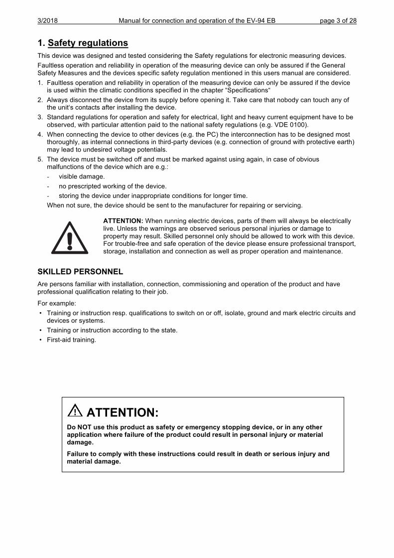
3/2018 Manual for connection and operation of the EV-94 EB page 3 of 28
1. Safety regulations This device was designed and tested considering the Safety regulations for electronic measuring devices. Faultless operation and reliability in operation of the measuring device can only be assured if the General Safety Measures and the devices specific safety regulation mentioned in this users manual are considered. 1. Faultless operation and reliability in operation of the measuring device can only be assured if the device
is used within the climatic conditions specified in the chapter “Specifications“ 2. Always disconnect the device from its supply before opening it. Take care that nobody can touch any of
the unit‘s contacts after installing the device. 3. Standard regulations for operation and safety for electrical, light and heavy current equipment have to be
observed, with particular attention paid to the national safety regulations (e.g. VDE 0100). 4. When connecting the device to other devices (e.g. the PC) the interconnection has to be designed most
thoroughly, as internal connections in third-party devices (e.g. connection of ground with protective earth) may lead to undesired voltage potentials.
5. The device must be switched off and must be marked against using again, in case of obvious malfunctions of the device which are e.g.: - visible damage. - no prescripted working of the device. - storing the device under inappropriate conditions for longer time.
When not sure, the device should be sent to the manufacturer for repairing or servicing.
ATTENTION: When running electric devices, parts of them will always be electrically live. Unless the warnings are observed serious personal injuries or damage to property may result. Skilled personnel only should be allowed to work with this device. For trouble-free and safe operation of the device please ensure professional transport, storage, installation and connection as well as proper operation and maintenance.
SKILLED PERSONNEL Are persons familiar with installation, connection, commissioning and operation of the product and have professional qualification relating to their job.
For example: • Training or instruction resp. qualifications to switch on or off, isolate, ground and mark electric circuits and
devices or systems. • Training or instruction according to the state. • First-aid training.
ATTENTION:
Do NOT use this product as safety or emergency stopping device, or in any other application where failure of the product could result in personal injury or material damage. Failure to comply with these instructions could result in death or serious injury and material damage.
3/2018 Manual for connection and operation of the EV-94 EB page 4 of 28
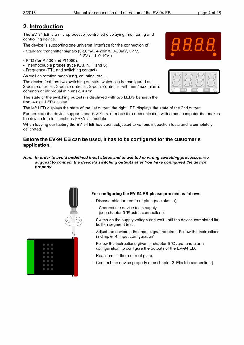
2. Introduction The EV-94 EB is a microprocessor controlled displaying, monitoring and controlling device. The device is supporting one universal interface for the connection of: - Standard transmitter signals (0-20mA, 4-20mA, 0-50mV, 0-1V, 0-2V and 0-10V ) - RTD (for Pt100 and Pt1000), - Thermocouple probes (type K, J, N, T and S) - Frequency (TTL and switching contact) As well as rotation measuring, counting, etc. ... The device features two switching outputs, which can be configured as 2-point-controller, 3-point-controller, 2-point-controller with min./max. alarm, common or individual min./max. alarm. The state of the switching outputs is displayed with two LED’s beneath the front 4-digit LED-display. The left LED displays the state of the 1st output, the right LED displays the state of the 2nd output. Furthermore the device supports one EASYBUS-interface for communicating with a host computer that makes the device to a full functions EASYBUS-module. When leaving our factory the EV-94 EB has been subjected to various inspection tests and is completely calibrated.
Before the EV-94 EB can be used, it has to be configured for the customer’s application.
Hint: In order to avoid undefined input states and unwanted or wrong switching processes, we suggest to connect the device’s switching outputs after You have configured the device properly.
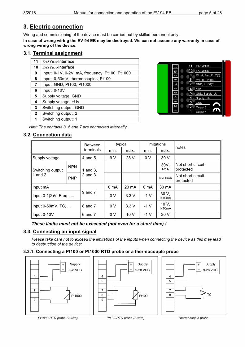
For configuring the EV-94 EB please proceed as follows: - Disassemble the red front plate (see sketch).
- Connect the device to its supply (see chapter 3 ‘Electric connection‘).
- Switch on the supply voltage and wait until the device completed its built-in segment test .
- Adjust the device to the input signal required. Follow the instructions in chapter 4 ‘Input configuration‘
- Follow the instructions given in chapter 5 ‘Output and alarm configuration‘ to configure the outputs of the EV-94 EB.
- Reassemble the red front plate.
- Connect the device properly (see chapter 3 'Electric connection‘)
3/2018 Manual for connection and operation of the EV-94 EB page 5 of 28
3. Electric connection Wiring and commissioning of the device must be carried out by skilled personnel only. In case of wrong wiring the EV-94 EB may be destroyed. We can not assume any warranty in case of wrong wiring of the device.
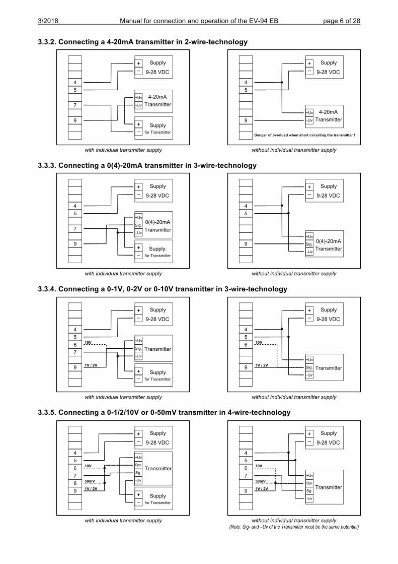
3.1. Terminal assignment 11 EASYBUS-Interface 10 EASYBUS-Interface 9 Input: 0-1V, 0-2V, mA, frequency, Pt100, Pt1000 8 Input: 0-50mV, thermocouples, Pt100 7 Input: GND, Pt100, Pt1000 6 Input: 0-10V 5 Supply voltage: GND 4 Supply voltage: +Uv 3 Switching output: GND 2 Switching output: 2 1 Switching output: 1
Hint: The contacts 3, 5 and 7 are connected internally.
3.2. Connection data
Between terminals
typical limitations notes
min. max. min. max.
Supply voltage 4 and 5 9 V 28 V 0 V 30 V
Switching output 1 and 2
NPN 1 and 3, 2 and 3
30V, I<1A
Not short circuit protected
PNP I<200mA Not short circuit protected
Input mA 9 and 7
0 mA 20 mA 0 mA 30 mA
Input 0-1(2)V, Freq., ... 0 V 3.3 V -1 V 30 V, I<10mA
Input 0-50mV, TC, ... 8 and 7 0 V 3.3 V -1 V 10 V, I<10mA
Input 0-10V 6 and 7 0 V 10 V -1 V 20 V
These limits must not be exceeded (not even for a short time) !
3.3. Connecting an input signal Please take care not to exceed the limitations of the inputs when connecting the device as this may lead to destruction of the device:
3.3.1. Connecting a Pt100 or Pt1000 RTD probe or a thermocouple probe
Pt1000-RTD probe (2-wire) Pt100-RTD probe (3-wire) Thermocouple probe
11
10
98
76
53
21
411
10
9
8
7
6
5
4
3
2
EASYBUS
1V, mA, Freq., Pt100(0)
mV, TC, Pt100
GND, Pt100(0)
10V
GND, Supply -Uv
Supply +Uv
GND
EASYBUS
1
Output 2
Output 1
TC
4
5
7
8
-
+
+_
Supply
9-28 VDC
Pt100
4
5
7
8
9
+_
Supply
9-28 VDC
Pt1000
+_
Supply
9-28 VDC
4
5
7
9
3/2018 Manual for connection and operation of the EV-94 EB page 6 of 28
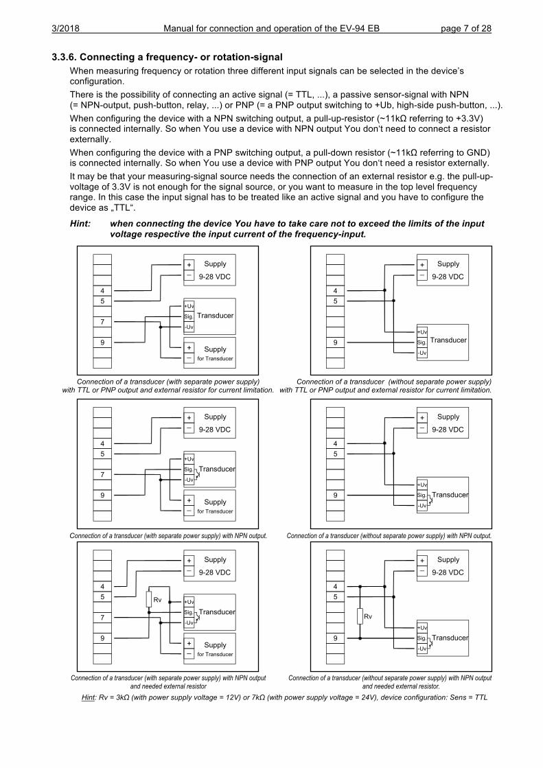
3.3.2. Connecting a 4-20mA transmitter in 2-wire-technology
with individual transmitter supply without individual transmitter supply
3.3.3. Connecting a 0(4)-20mA transmitter in 3-wire-technology
with individual transmitter supply without individual transmitter supply
3.3.4. Connecting a 0-1V, 0-2V or 0-10V transmitter in 3-wire-technology
with individual transmitter supply without individual transmitter supply
3.3.5. Connecting a 0-1/2/10V or 0-50mV transmitter in 4-wire-technology
with individual transmitter supply without individual transmitter supply (Note: Sig- and –Uv of the Transmitter must be the same potential)
+_
Supply
9-28 VDC
4-20mA
Transmitter
+Uv
-Uv
+_
Supply
for Transmitter
4
5
7
9
+_
Supply
9-28 VDC
4-20mA
Transmitter
+Uv
-Uv
4
5
9
0(4)-20mA
Transmitter
+Uv
Sig.
-Uv
+_
Supply
9-28 VDC
+_
Supply:
for Transmitter
4
5
7
90(4)-20mA
Transmitter
+Uv
Sig.
-Uv
+_
Supply
9-28 VDC
4
5
9
Transmitter
+Uv
Sig.
-Uv
+_
Supply
9-28 VDC
+_
Supply
for Transmitter
4
5
6
7
9
10V
1V / 2V
+_
Supply
9-28 VDC
4
5
6
9
10V
1V / 2VTransmitter
+Uv
Sig.
-Uv
+_
Supply
9-28 VDC
+_
Supply
for Transmitter
4
5
6
7
8
9
10V
1V / 2V
Transmitter
+Uv
Sig-
-Uv
Sig+
50mV
Transmitter
+Uv
Sig-
-Uv
Sig+
+_
Supply
9-28 VDC
4
5
6
7
9
10V
1V / 2V
50mV
Danger of overload when short circuiting the transmitter !
3/2018 Manual for connection and operation of the EV-94 EB page 7 of 28
3.3.6. Connecting a frequency- or rotation-signal When measuring frequency or rotation three different input signals can be selected in the device’s configuration. There is the possibility of connecting an active signal (= TTL, ...), a passive sensor-signal with NPN (= NPN-output, push-button, relay, ...) or PNP (= a PNP output switching to +Ub, high-side push-button, ...). When configuring the device with a NPN switching output, a pull-up-resistor (~11kΩ referring to +3.3V) is connected internally. So when You use a device with NPN output You don‘t need to connect a resistor externally. When configuring the device with a PNP switching output, a pull-down resistor (~11kΩ referring to GND) is connected internally. So when You use a device with PNP output You don‘t need a resistor externally. It may be that your measuring-signal source needs the connection of an external resistor e.g. the pull-up-voltage of 3.3V is not enough for the signal source, or you want to measure in the top level frequency range. In this case the input signal has to be treated like an active signal and you have to configure the device as „TTL“.
Hint: when connecting the device You have to take care not to exceed the limits of the input voltage respective the input current of the frequency-input.
Connection of a transducer (with separate power supply) Connection of a transducer (without separate power supply) with TTL or PNP output and external resistor for current limitation. with TTL or PNP output and external resistor for current limitation.
Connection of a transducer (with separate power supply) with NPN output. Connection of a transducer (without separate power supply) with NPN output.
Connection of a transducer (with separate power supply) with NPN output Connection of a transducer (without separate power supply) with NPN output and needed external resistor and needed external resistor. Hint: Rv = 3kΩ (with power supply voltage = 12V) or 7kΩ (with power supply voltage = 24V), device configuration: Sens = TTL
+_
Supply
9-28 VDC
+_
Supply
for Transducer
4
5
7
9
Transducer
+Uv
Sig.
-Uv
+_
Supply
9-28 VDC
4
5
9 Transducer
+Uv
Sig.
-Uv
+_
Supply
9-28 VDC
4
5
7
9+_
Supply
for Transducer
Rv
Transducer
+Uv
Sig.
-Uv
+_
Supply
9-28 VDC
4
5
9
Rv
Transducer
+Uv
Sig.
-Uv
Transducer
+Uv
Sig.
-Uv
+_
Supply
9-28 VDC
+_
Supply
for Transducer
4
5
7
9
+_
Supply
9-28 VDC
4
5
9 Transducer
+Uv
Sig.
-Uv
3/2018 Manual for connection and operation of the EV-94 EB page 8 of 28
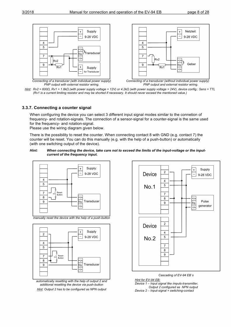
Connecting of a transducer (with individual power supply) Connecting of a transducer (without individual power supply) PNP output with external resistor wiring. PNP output and external resistor wiring. Hint: Rv2 = 600Ω, Rv1 = 1.8kΩ (with power supply voltage = 12V) or 4.2kΩ (with power supply voltage = 24V), device config.: Sens = TTL (Rv1 is a current limiting resistor and may be shorted if necessary. It should never exceed the mentioned value.)
3.3.7. Connecting a counter signal When configuring the device you can select 3 different input signal modes similar to the connetion of frequency- and rotation-signals. The connection of a sensor-signal for a counter-signal is the same used for the frequency- and rotation-signal. Please use the wiring diagram given below.
There is the possibility to reset the counter. When connecting contact 8 with GND (e.g. contact 7) the counter will be reset. You can do this manually (e.g. with the help of a push-button) or automatically (with one switching output of the device).
Hint: When connecting the device, take care not to exceed the limits of the input-voltage or the input-current of the frequency input.
manually reset the device with the help of a push-button
automatically resetting with the help of output 2 and additional resetting the device via push-button Hint: Output 2 has to be configured as NPN output
Cascading of EV-94 EB`s Hint for EV-94 EB: Device 1 – Input signal like impuls-transmitter, Output 2 configured as NPN output Device 2 – Input-signal = switching-contact
Reset-Button
+_
Supply:
9-28 VDC
4
5
7
8
9 Transducer
+Uv
Sig.
-Uv
+_
Supply
9-28 VDC2
4
5
7
8
9
Device
No.1
Pulse
generator
+Uv
Sig.
-Uv
2
4
5
7
8
9
Device
No.2
Reset-Button
+_
Supply
9-28 VDC2
4
5
7
8
9 Transducer
+Uv
Sig.
-Uv
+_
Supply
9-28 VDC
4
5
7
9+_
Supply
for Transducer
Transducer
+Uv
Sig.
-Uv
Rv2
Rv1
+_
Netzteil:
9-28 VDC
4
5
7
9 Geber
+Uv
Sig.
-Uv
Rv2
Rv1
3/2018 Manual for connection and operation of the EV-94 EB page 9 of 28
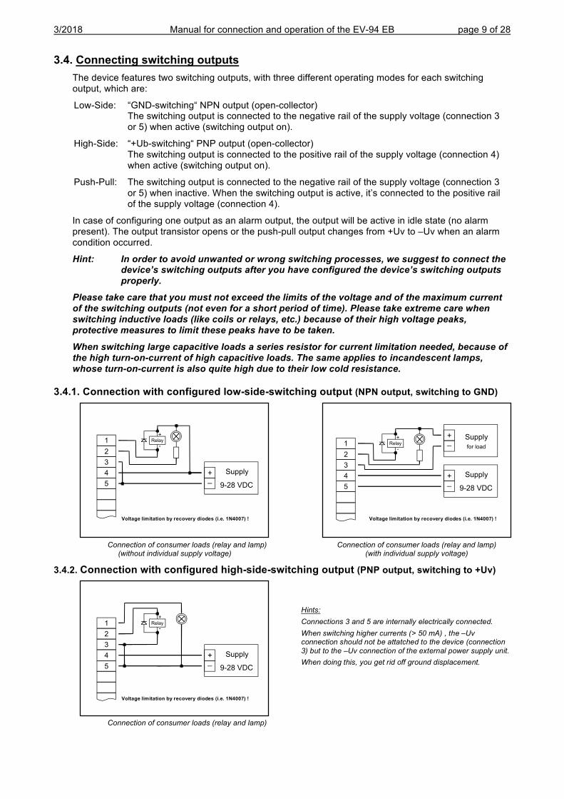
3.4. Connecting switching outputs The device features two switching outputs, with three different operating modes for each switching output, which are:
Low-Side: “GND-switching“ NPN output (open-collector) The switching output is connected to the negative rail of the supply voltage (connection 3 or 5) when active (switching output on).
High-Side: “+Ub-switching“ PNP output (open-collector) The switching output is connected to the positive rail of the supply voltage (connection 4) when active (switching output on).
Push-Pull: The switching output is connected to the negative rail of the supply voltage (connection 3 or 5) when inactive. When the switching output is active, it’s connected to the positive rail of the supply voltage (connection 4).
In case of configuring one output as an alarm output, the output will be active in idle state (no alarm present). The output transistor opens or the push-pull output changes from +Uv to –Uv when an alarm condition occurred.
Hint: In order to avoid unwanted or wrong switching processes, we suggest to connect the device’s switching outputs after you have configured the device’s switching outputs properly.
Please take care that you must not exceed the limits of the voltage and of the maximum current of the switching outputs (not even for a short period of time). Please take extreme care when switching inductive loads (like coils or relays, etc.) because of their high voltage peaks, protective measures to limit these peaks have to be taken.
When switching large capacitive loads a series resistor for current limitation needed, because of the high turn-on-current of high capacitive loads. The same applies to incandescent lamps, whose turn-on-current is also quite high due to their low cold resistance.
3.4.1. Connection with configured low-side-switching output (NPN output, switching to GND)
Connection of consumer loads (relay and lamp) Connection of consumer loads (relay and lamp) (without individual supply voltage) (with individual supply voltage)
3.4.2. Connection with configured high-side-switching output (PNP output, switching to +Uv)
Connection of consumer loads (relay and lamp)
+_
Supply
9-28 VDC
+_
Supply
for load1
2
3
4
5
+
-Relay
Hints: Connections 3 and 5 are internally electrically connected. When switching higher currents (> 50 mA) , the –Uv connection should not be attatched to the device (connection 3) but to the –Uv connection of the external power supply unit. When doing this, you get rid off ground displacement.
+_
Supply
9-28 VDC
1
2
3
4
5
+
-Relay
+_
Supply
9-28 VDC
1
2
3
4
5
+
-Relay
Voltage limitation by recovery diodes (i.e. 1N4007) ! Voltage limitation by recovery diodes (i.e. 1N4007) !
Voltage limitation by recovery diodes (i.e. 1N4007) !
3/2018 Manual for connection and operation of the EV-94 EB page 10 of 28
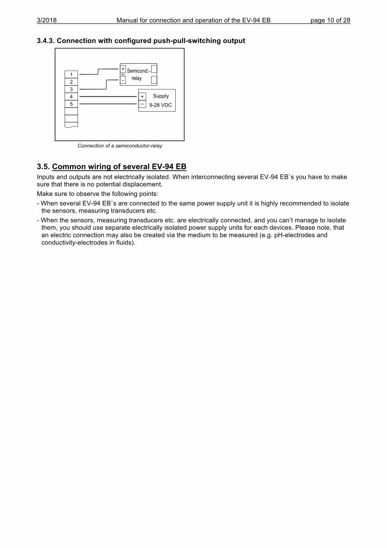
3.4.3. Connection with configured push-pull-switching output
Connection of a semiconductor-relay
3.5. Common wiring of several EV-94 EB Inputs and outputs are not electrically isolated. When interconnecting several EV-94 EB`s you have to make sure that there is no potential displacement. Make sure to observe the following points: - When several EV-94 EB`s are connected to the same power supply unit it is highly recommended to isolate
the sensors, measuring transducers etc. - When the sensors, measuring transducers etc. are electrically connected, and you can’t manage to isolate
them, you should use separate electrically isolated power supply units for each devices. Please note, that an electric connection may also be created via the medium to be measured (e.g. pH-electrodes and conductivity-electrodes in fluids).
+
-
UinSemicond.-
relay
+_
Supply
9-28 VDC
1
2
3
4
5
3/2018 Manual for connection and operation of the EV-94 EB page 11 of 28
4. Configuration of the device Please note: When you are configuring the device and don’t press any button for more than 60 sec. the configuration of the device will be cancelled. The changes you made will not be saved and will be lost!
Hint: The buttons 2 and 3 are featured with a ‘roll-function‘. When pressing the button once the value will be raised (button 2) by one or lowered (button 3) by one. When holding the button pressed for longer than 1 sec. the value starts counting up or down, the counting speed will be raised after a short period of time. The device also features a ‘overflow-function‘, when reaching the upper limit of the range, the device switches to the lower limit, vice versa.
4.1. Selecting an input signal type - Turn the device on and wait until it completed its built-in segment test.
- Press button 2 for >2 sec. (e.g. with a small screw driver) The device displays “InP“ ('INPUT').
- Use button 2 or button 3 (middle resp. right button) to select the input signal (see table below).
- Validate the selection with button 1 (the left button). The display will show “InP“ again.
Depending on the selected input signal, additional configurations will be needed.
Input type Signal to select as input proceed in chapter
Voltage signal 0 – 10 V
U 4.2 0 – 2 V 0 – 1 V 0 – 50 mV
Current signal 4 – 20 mA I 4.2
0 – 20 mA RTD Pt100 (0.1°C)
t.rES 4.3 Pt100 (1°C) Pt1000
Thermocouples NiCr-Ni (Type K)
t.tc 4.3 Pt10Rh-Pt (Type S) NiCrSi-NiSi (Type N) Fe-CuNi (Type J) Cu-CuNi (Type T)
Frequency TTL-signal FrEq 4.4
Switch-contact NPN, PNP Rotation TTL-signal
rPn 4.5 Switch-contact NPN, PNP
Counter up TTL-signal Co.uP 4.6
Switch-contact NPN, PNP Counter down TTL-signal
Co.dn 4.6 Switch-contact NPN, PNP
Interface mode Serial interface SEri 4.7
Please note: When changing the measuring mode “InP“, the input signal “SEnS“ and the display-unit “Unit“ all settings will be changed to factory default. You have to set all the other settings. This also regards the settings for offset and slope-adjustment as well as the switching points!
Button 1 Button 2 Button 3
3/2018 Manual for connection and operation of the EV-94 EB page 12 of 28
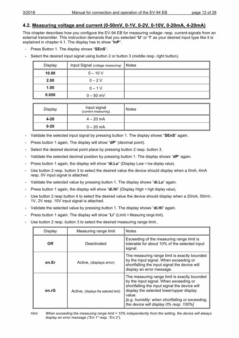
4.2. Measuring voltage and current (0-50mV, 0-1V, 0-2V, 0-10V, 0-20mA, 4-20mA) This chapter describes how you configure the EV-94 EB for measuring voltage- resp. current-signals from an external transmitter. This instruction demands that you selected “U“ or “I“ as your desired input type like it is explained in chapter 4.1. The display has to show “InP“.
- Press Button 1. The display shows “SEnS“.
- Select the desired input signal using button 2 or button 3 (middle resp. right button).
Display Input Signal (voltage measuring) Notes
10.00 0 – 10 V
2.00 0 – 2 V
1.00 0 – 1 V
0.050 0 – 50 mV
Display Input signal (current measuring) Notes
4-20 4 – 20 mA
0-20 0 – 20 mA
- Validate the selected input signal by pressing button 1. The display shows “SEnS“ again.
- Press button 1 again, The display will show “dP“ (decimal point).
- Select the desired decimal point place by pressing button 2 resp. button 3.
- Validate the selected decimal position by pressing button 1. The display shows “dP“ again.
- Press button 1 again, the display will show “di.Lo“ (Display Low = low display value).
- Use button 2 resp. button 3 to select the desired value the device should display when a 0mA, 4mA resp. 0V input signal is attached.
- Validate the selected value by pressing button 1. The display shows “di.Lo“ again.
- Press button 1 again, the display will show “di.Hi“ (Display High = high display value).
- Use button 2 resp button 4 to select the desired value the device should display when a 20mA, 50mV, 1V, 2V resp. 10V input signal is attached.
- Validate the selected value by pressing button 1. The display shows “di.Hi“ again.
- Press button 1 again. The display will show “Li“ (Limit = Measuring range limit).
- Use button 2 resp. button 3 to select the desired measuring range limit..
Display Measuring range limit Notes
Off Deactivated Exceeding of the measuring range limit is tolerable for about 10% of the selected input signal.
on.Er Active, (displays error)
The measuring range limit is exactly bounded by the input signal. When exceeding or shortfalling the input signal the device will display an error message.
on.rG Active, (displays the selected limit)
The measuring range limit is exactly bounded by the input signal. When exceeding or shortfalling the input signal the device will display the selected lower/upper display value. [e.g. humidity: when shortfalling or exceeding, the device will display 0% resp. 100%]
Hint: When exceeding the measuring range limit > 10% independently from the setting, the device will always display an error message (“Err.1“ resp. “Err.2“).
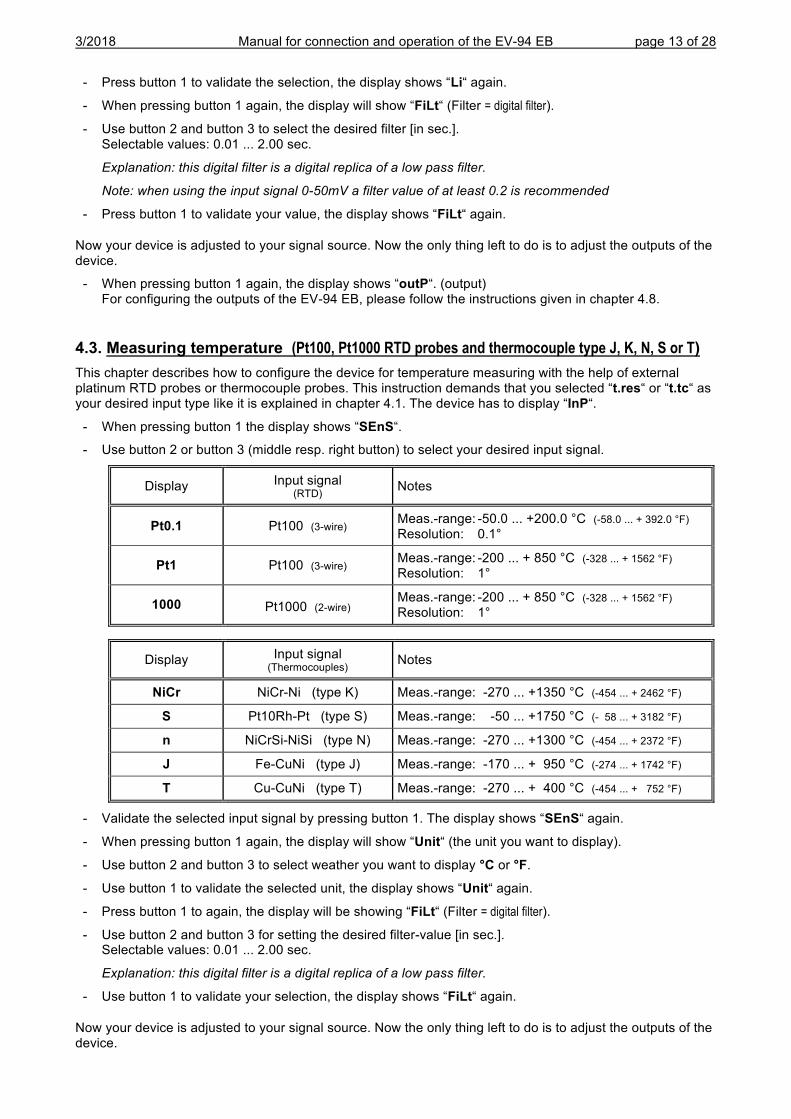
3/2018 Manual for connection and operation of the EV-94 EB page 13 of 28
- Press button 1 to validate the selection, the display shows “Li“ again.
- When pressing button 1 again, the display will show “FiLt“ (Filter = digital filter).
- Use button 2 and button 3 to select the desired filter [in sec.]. Selectable values: 0.01 ... 2.00 sec.
Explanation: this digital filter is a digital replica of a low pass filter.
Note: when using the input signal 0-50mV a filter value of at least 0.2 is recommended
- Press button 1 to validate your value, the display shows “FiLt“ again.
Now your device is adjusted to your signal source. Now the only thing left to do is to adjust the outputs of the device.
- When pressing button 1 again, the display shows “outP“. (output) For configuring the outputs of the EV-94 EB, please follow the instructions given in chapter 4.8.
4.3. Measuring temperature (Pt100, Pt1000 RTD probes and thermocouple type J, K, N, S or T) This chapter describes how to configure the device for temperature measuring with the help of external platinum RTD probes or thermocouple probes. This instruction demands that you selected “t.res“ or “t.tc“ as your desired input type like it is explained in chapter 4.1. The device has to display “InP“.
- When pressing button 1 the display shows “SEnS“.
- Use button 2 or button 3 (middle resp. right button) to select your desired input signal.
Display Input signal (RTD) Notes
Pt0.1 Pt100 (3-wire) Meas.-range: -50.0 ... +200.0 °C (-58.0 ... + 392.0 °F) Resolution: 0.1°
Pt1 Pt100 (3-wire) Meas.-range: -200 ... + 850 °C (-328 ... + 1562 °F) Resolution: 1°
1000 Pt1000 (2-wire) Meas.-range: -200 ... + 850 °C (-328 ... + 1562 °F) Resolution: 1°
Display Input signal (Thermocouples) Notes
NiCr NiCr-Ni (type K) Meas.-range: -270 ... +1350 °C (-454 ... + 2462 °F)
S Pt10Rh-Pt (type S) Meas.-range: -50 ... +1750 °C (- 58 ... + 3182 °F)
n NiCrSi-NiSi (type N) Meas.-range: -270 ... +1300 °C (-454 ... + 2372 °F)
J Fe-CuNi (type J) Meas.-range: -170 ... + 950 °C (-274 ... + 1742 °F)
T Cu-CuNi (type T) Meas.-range: -270 ... + 400 °C (-454 ... + 752 °F)
- Validate the selected input signal by pressing button 1. The display shows “SEnS“ again.
- When pressing button 1 again, the display will show “Unit“ (the unit you want to display).
- Use button 2 and button 3 to select weather you want to display °C or °F.
- Use button 1 to validate the selected unit, the display shows “Unit“ again.
- Press button 1 to again, the display will be showing “FiLt“ (Filter = digital filter).
- Use button 2 and button 3 for setting the desired filter-value [in sec.]. Selectable values: 0.01 ... 2.00 sec.
Explanation: this digital filter is a digital replica of a low pass filter.
- Use button 1 to validate your selection, the display shows “FiLt“ again.
Now your device is adjusted to your signal source. Now the only thing left to do is to adjust the outputs of the device.
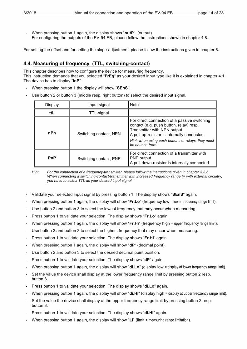
3/2018 Manual for connection and operation of the EV-94 EB page 14 of 28
- When pressing button 1 again, the display shows “outP“. (output) For configuring the outputs of the EV-94 EB, please follow the instructions shown in chapter 4.8.
For setting the offset and for setting the slope-adjustment, please follow the instructions given in chapter 6.
4.4. Measuring of frequency (TTL, switching-contact) This chapter describes how to configure the device for measuring frequency. This instruction demands that you selected “FrEq“ as your desired input type like it is explained in chapter 4.1. The device has to display “InP“.
- When pressing button 1 the display will show “SEnS“.
- Use button 2 or button 3 (middle resp. right button) to select the desired input signal.
Display Input signal Note
ttL TTL-signal
nPn Switching contact, NPN
For direct connection of a passive switching contact (e.g. push button, relay) resp. Transmitter with NPN output. A pull-up-resistor is internally connected. Hint: when using push-buttons or relays, they must be bounce-free!
PnP Switching contact, PNP For direct connection of a transmitter with PNP output. A pull-down-resistor is internally connected.
Hint: For the connection of a frequency-transmitter, please follow the instructions given in chapter 3.3.6 When connecting a switching-contact-transmitter with increased frequency range (= with external circuitry) you have to select TTL as your desired input signal.
- Validate your selected input signal by pressing button 1. The display shows “SEnS“ again.
- When pressing button 1 again, the display will show “Fr.Lo“ (frequency low = lower frequency range limit).
- Use button 2 and button 3 to select the lowest frequency that may occur when measuring.
- Press button 1 to validate your selection. The display shows “Fr.Lo“ again.
- When pressing button 1 again, the display will show “Fr.Hi“ (frequency high = upper frequency range limit).
- Use button 2 and button 3 to select the highest frequency that may occur when measuring.
- Press button 1 to validate your selection. The display shows “Fr.Hi“ again.
- When pressing button 1 again, the display will show “dP“ (decimal point).
- Use button 2 and button 3 to select the desired decimal point position.
- Press button 1 to validate your selection. The display shows “dP“ again.
- When pressing button 1 again, the display will show “di.Lo“ (display low = display at lower frequency range limit).
- Set the value the device shall display at the lower frequency range limit by pressing button 2 resp. button 3.
- Press button 1 to validate your selection. The display shows “di.Lo“ again.
- When pressing button 1 again, the display will show “di.Hi“ (display high = display at upper freqzency range limit).
- Set the value the device shall display at the upper frequency range limit by pressing button 2 resp. button 3.
- Press button 1 to validate your selection. The display shows “di.Hi“ again.
- When pressing button 1 again, the display will show “Li“ (limit = measuring range limitation).
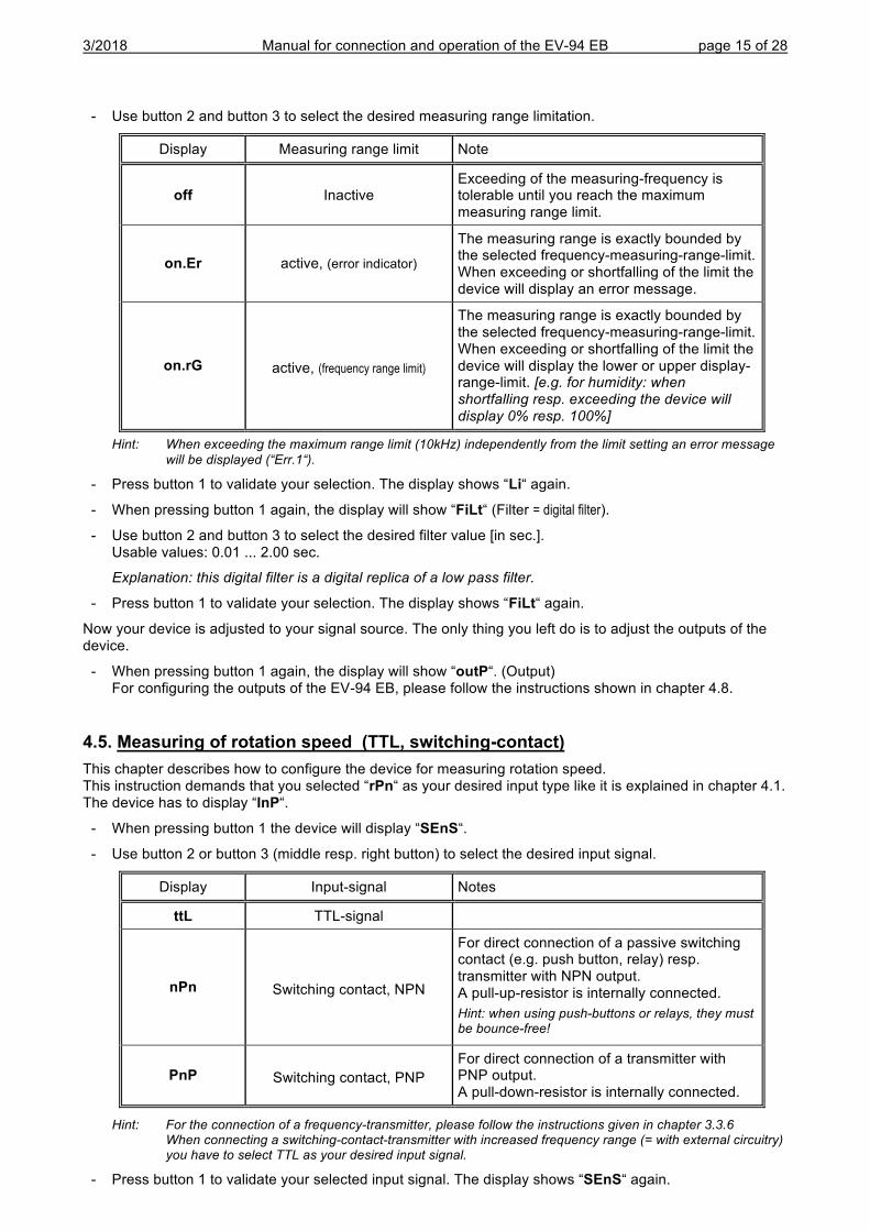
3/2018 Manual for connection and operation of the EV-94 EB page 15 of 28
- Use button 2 and button 3 to select the desired measuring range limitation.
Display Measuring range limit Note
off Inactive Exceeding of the measuring-frequency is tolerable until you reach the maximum measuring range limit.
on.Er active, (error indicator)
The measuring range is exactly bounded by the selected frequency-measuring-range-limit. When exceeding or shortfalling of the limit the device will display an error message.
on.rG active, (frequency range limit)
The measuring range is exactly bounded by the selected frequency-measuring-range-limit. When exceeding or shortfalling of the limit the device will display the lower or upper display-range-limit. [e.g. for humidity: when shortfalling resp. exceeding the device will display 0% resp. 100%]
Hint: When exceeding the maximum range limit (10kHz) independently from the limit setting an error message will be displayed (“Err.1“).
- Press button 1 to validate your selection. The display shows “Li“ again.
- When pressing button 1 again, the display will show “FiLt“ (Filter = digital filter).
- Use button 2 and button 3 to select the desired filter value [in sec.]. Usable values: 0.01 ... 2.00 sec.
Explanation: this digital filter is a digital replica of a low pass filter.
- Press button 1 to validate your selection. The display shows “FiLt“ again.
Now your device is adjusted to your signal source. The only thing you left do is to adjust the outputs of the device.
- When pressing button 1 again, the display will show “outP“. (Output) For configuring the outputs of the EV-94 EB, please follow the instructions shown in chapter 4.8.
4.5. Measuring of rotation speed (TTL, switching-contact) This chapter describes how to configure the device for measuring rotation speed. This instruction demands that you selected “rPn“ as your desired input type like it is explained in chapter 4.1. The device has to display “InP“.
- When pressing button 1 the device will display “SEnS“.
- Use button 2 or button 3 (middle resp. right button) to select the desired input signal.
Display Input-signal Notes
ttL TTL-signal
nPn Switching contact, NPN
For direct connection of a passive switching contact (e.g. push button, relay) resp. transmitter with NPN output. A pull-up-resistor is internally connected. Hint: when using push-buttons or relays, they must be bounce-free!
PnP Switching contact, PNP For direct connection of a transmitter with PNP output. A pull-down-resistor is internally connected.
Hint: For the connection of a frequency-transmitter, please follow the instructions given in chapter 3.3.6 When connecting a switching-contact-transmitter with increased frequency range (= with external circuitry) you have to select TTL as your desired input signal.
- Press button 1 to validate your selected input signal. The display shows “SEnS“ again.
3/2018 Manual for connection and operation of the EV-94 EB page 16 of 28
- When pressing button 1 again, the display will show “diu“ (divisor).
- Use button 2 and 3 to select your desired divisor. Set the divisor to the pulses per rotation the transmitter supplies.
- Press button 1 to validate your selection. The display shows “diu“ again.
- When pressing button 1 again, the display will show “dP“ (decimal point).
- Use button 2 and button 3 to select the desired decimal point position.
Use the decimal point position to change the resolution of your measurement. The more the decimal point position is on the left, the finer the resolution will become. Please note that you lower the maximum value that can be displayed, either. Example: your engine runs with 50 rotations per minute. With no decimal point the device will display something like 49 – 50 – 51, the maximum value that can be displayed is 9999 rotations per minute. With the decimal point position on the left e.g. XX.XX the device will display something like 49.99 – 50.00 – 50.01, but the maximum value that can be displayed is 99.99 rotations per minute.
- Press button 1 to validate your selection. The display shows “dP“ again.
Now your device is adjusted to your signal source. The only thing left to do is to adjust the outputs of the device.
- When pressing button 1 again, the display will show “outP“. (Output) For configuring the outputs of the EV-94 EB, please follow the instructions shown in chapter 4.8.
4.6. Up-/Downwards counter (TTL, switching-contact) The upwards counter starts counting upwards from 0 according to its settings. The downwards counter starts counting downwards from the upper value that had been selected.
Feature: The current value of the counter can be reset anytime by connecting pin 8 to GND (e.g. pin 7). The counter starts from its beginning as you disconnect pin 8 and pin 7.
The current counter value won‘t be lost if the voltage supply is disconnected. After restarting the counter starts from this value.
This chapter describes how to configure the device as a counter. This instruction demands that you selected “Co.up“ or “Co.dn“ as your desired input type like it is explained in chapter 4.1.The device has to display “InP“.
- When pressing button 1 the display will show “SEnS“.
- Use button 2 or button 3 (middle resp. right button) to select the desired input signal.
Display Input-signal Note
ttL TTL-signal
nPn Switching contact, NPN
For direct connection of a passive switching contact (e.g. push button, relay) resp. transmitter with NPN output. A pull-up-resistor is internally connected. Hint: when using push-buttons or relays, they must be bounce-free!
PnP Switching contact, PNP For direct connection of a transmitter with PNP output. A pull-down-resistor is internally connected.
Hint: For connecting a frequency-transmitter, please follow the instructions given in chapter 3.3.7 When connecting a switching-contact-transmitter with increased frequency range (= with external circuit) you have to select TTL as your desired input signal.
- Press button 1 to validate your selected input signal. The display shows “SenS“ again.
- When pressing button 1 again, the device will be displaying “EdGE“ (signal edge).
3/2018 Manual for connection and operation of the EV-94 EB page 17 of 28
- Use button 2 or button3 (middle resp. right button) to select the desired signal edge.
Display Signal edge Note
PoS Positive The counter is triggered on the positive (rising) edge.
nEG Negative The counter is triggered on the negative (falling) edge.
- Press button 1 to validate your selection, the display shows “EdGE“ again.
- When pressing button 1 again, the display will show “diu“ (divisor = pre-scaling factor).
- Use button 2 and button 3 to select the desired pre-scaling factor.
The incoming pulses will be divided with the selected pre-scaling factor, after that they will be transmitted to the device for further processing. By this factor you can adapt the device to your transmitter or select a pre-scaling factor for large values Example 1: Your flow rate transmitter supplies 165 pulses per litre. When setting a pre-scaling factor of 165 every 165th pulse (so 1 pulse per litre) will be used for further processing. Example 2: Your transmitter is supplying about 5 000 000 pulses during the measurement, which exceeds the limit of the GIA20EB. But when setting a pre-scaling factor of 1000 only every 1000th pulse is used for further processing. So you only got a value 5000 which won’t exceed the limit of the EV-94 EB.
- Press button 1 to validate your selection. The display shows “diu“ again.
- Press button 1 again. The display shows “Co.Hi“ (counter high = upper counting range limit).
- Use button 2 and button 3 to select the maximum pulse-count (after pre-scaling factor) for the counting process.
Example: Your flow rate transmitter is supplying 1800 pulses per litre, you selected a pre-scaling factor of 100 and you are expecting a maximum flow rate of 300 litres during the measurement. With a pre-scaling factor of 100 selected, you will get 18 pulses per litre. With a maximum flow rate of 300 litres you will be getting a pulse count of 18 * 300 = 5400.
- Press button 1 to validate your selection. The display shows “Co.Hi“ again.
- When pressing button 1 again, the device will be displaying “dP“ (decimal point).
- Use button 2 and button 3 to select the desired decimal point position.
- Press button 1 to validate your selected decimal point position. The display shows “dP“ again.
- Press button 1 again. The display shows “di.Hi“ (display high = upper display range limit).
- Use button 2 and button 3 to set the value to be displayed when the maximum pulse (setting of co.Hi) count is reached.
Example: Your flow rate transmitter is supplying 1800 pulses per litre and you are expecting a maximum flow rate of 300 litres. You selected a pre-scaling factor of 100 and a counter range limit of 5400. When wanting a resolution of 0.1 litres shown in the display of the device you would have to set the decimal point position to ---.- and a display range limit of 300.0.
- Press button 1 to validate your selection. The display shows “di.Hi“ again. - Press button 1. The display will show “Li“ (Limit = measuring range limit). - Use button 2 and button 3 to select the desired measuring range limit (counter range limit).
Display Measuring range limit Note
off Inactive Exceeding of the counter range is tolerable until you reach the maximum measuring range limit.
on.Er active, (error indicator)
The measuring range is exactly bounded by the selected counter-range-limit. When exceeding or shortfalling of the limit the device will display an error message.
on.rG active, (measuring range limit)
The measuring range is exactly bounded by the selected counter-range-limit. When exceeding or shortfalling of the limit the device will display the upper counter-range-limit or 0
Hint: The lower counter-range-limit (for configured downwards counter) is fixed to 0.
3/2018 Manual for connection and operation of the EV-94 EB page 18 of 28
- Press button 1 to validate your selection. The display shows “Li“ again.
Now your device is adjusted to your signal source. The only thing left to do is to adjust the outputs of the device.
- When pressing button 1 again, the display will show “outP“. (Output) For configuring the outputs of the EV-94 EB, please follow the instructions shown in chapter 4.8.
4.7. Interface mode When the device is in the interface mode it won’t make any measurements by itself. The value shown in the device’s display is sent via serial interface. But the switching and alarm functions of the displayed value are still available. The EASYBUS-Address of the device needed for the communication can be set manually with the device itself or with the help of an EASYBUS-software (like EbxKonfig). Please note, when carrying out an EASYBUS-system-initialisation the device’s address will be reset automatically.
This chapter describes how to configure the device as an EASYBUS-display. This instruction demands that you selected “SEri“ as your desired input type like it is explained in chapter 4.1 The device has to display “InP“.
- When pressing button 1 again, the device will display “Adr“ (address).
- Use button 2 and button 3 to select the desired address [0 ... 239] of the device.
- Press button 1 to validate the selected device address. The display shows “Adr“ again.
You don’t need any further configuration but the outputs.
- When pressing button 1 again, the device will be displaying “outP“ (output). For configuring the outputs please follow the instructions given in chapter 4.8.
4.8. Selection of the output function - After configuration of the input (chapter 4.2 – 4.7) you have to select the output function.
The display shows “outP“ (output).
- Use button 2 and button 3 (middle resp. right button) to select the desired output-function.
Description Function To select as
output See chapter Output 1 Output 2
No output, device is used as display unit --- --- no --
2-point-controller digital 2-point-controller
--- 2P 5.1
3-point-controller digital 2-point-controller
digital 2-point-controller
3P 5.1
2-point-controller with Min-/Max-alarm
digital 2-point-controller
Min-/Max-alarm 2P.AL 5.2
Min-/Max-alarm, common --- Min-/Max-alarm AL.F1 5.3
Min-/Max-alarm, individual Max-alarm Min-alarm AL.F2 5.3
- Press button 1 to validate the selected output function. The display shows “outP“ again.
Depending on your output function setting, it may be possible that one or more settings described below won’t be available.
3/2018 Manual for connection and operation of the EV-94 EB page 19 of 28
- When pressing button 1 again, the device will display “1.dEL“ (delay of output 1).
- Use button 2 and button 3 to set the desired value [in sec.] for the switching-delay of output 1.
- Press button 1 to validate the selection. The display shows “1.dEL“ again.
- When pressing button 1 again, the device will display “1.out“ (kind of output 1).
- Use button 2 or button 3 (middle resp. right button) to select the desired output function.
Display Kind of output Note
nPn Low-Side NPN, open collector, switching GND
PnP High-Side PNP, open collector, switching +Ub
Pu.Pu Push-Pull
- Press button 1 to validate the selection. The display shows “ 1.out“ again.
- When pressing button 1 again, the device will display “1.Err“ (preferred state of output 1).
- Use button 2 and button 3 (middle resp. right button) to set the desired initial state in case of an error.
Display Preferred state of the output Note
off Inactive in case of an error Low-/High-side-switch is opened in case of an error. Push-Pull-output is low in case of an error.
on Active in case of an error Low-/High-side-switch is closed in case of an error. Push-Pull-output is high in case of an error.
- Press button 1 to validate the selection. The display shows “1.Err“ again.
- In case you selected a 3-point-controller you have to make the following settings similar to the settings you already made for output 1: “2.dEL“ (delay of output 2), “2.out“ (kind of output 2), “2.Err“ (preferred state of output 2).
- When pressing button 1 again, (only if you configured the device with min-/max-alarm) the device will be displaying “A.out“ (kind of the alarm-output).
- Use button 2 or button 3 (middle resp. right button) to select the desired kind of the alarm-output.
Display Kind of the alarm-output Note
nPn Low-Side NPN, open collector, switching GND
Switching output is closed (connected to GND) as long there is no alarm-condition, and is opened if there is an alarm-condition.
PnP High-Side PNP, open collector, switching +Ub
Switching output is closed (is under voltage) as long there is no alarm-condition, and is opened if there is an alarm-condition.
Pu.Pu Push-Pull Switching output is high with no alarm-condition and changes to low if there is an alarm-condition.
Please Note: The switching outputs are inverted when using them as alarm-outputs! This means as long there is no alarm-condition, the switching output will be active! In case of an alarm-condition the output will become inactive!
Note: When using the output function “min-/max-alarm, individual“ the setting for kind of alarm output is used for both alarm-outputs.
- Press button 1 to validate the selection. The display shows “ A.out“ again.
Depending on the selected output function you have to make the settings for switching resp. alarm points. See description in chapter „switchpoints resp. alarm-boundaries“ for further information.
Hint: The settings for the switching and alarm points can be made later in an extra menu (see chapter 5)
3/2018 Manual for connection and operation of the EV-94 EB page 20 of 28
5. Switchpoints resp. alarm-boundaries Please note: The settings of the switchpoints will be cancelled, when no button was pressed for more than
60 sec. changes you may have made already won‘t be saved and will be lost!
Please note: The settings of the switchpoints and alarm-boundaries will automatically be reset to factory default when any changes for the settings “InP”, “SEnS“ resp. “Unit“ had been made!
Hint: The buttons 2 and 3 are featured with a ‘roll-function‘. When pressing the button once the value will be raised (button 2) by one or lowered (button 3) by one. When holding the button pressed for longer than 1 sec. the value starts counting up or down, the counting speed will be raised after a short period of time. The device also features an ‘overflow-function‘, when reaching the upper limit the device switches to the lower limit, vice versa.
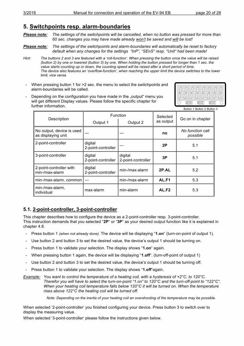
- When pressing button 1 for >2 sec. the menu to select the switchpoints and alarm-boundaries will be called.
- Depending on the configuration you have made in the „output“ menu you will get different Display values. Please follow the specific chapter for further information.
Description Function Selected
as output Go on in chapter Output 1 Output 2
No output, device is used as displaying unit --- --- no No function call
possible
2-point-controller digital 2-point-controller --- 2P 5.1
3-point-controller digital 2-point-controller
digital 2-point-controller 3P 5.1
2-point-controller with min-/max-alarm
digital 2-point-controller min-/max-alarm 2P.AL 5.2
min-/max-alarm, common --- min-/max-alarm AL.F1 5.3
min-/max-alarm, individual max-alarm min-alarm AL.F2 5.3
5.1. 2-point-controller, 3-point-controller This chapter describes how to configure the device as a 2-point-controller resp. 3-point-controller. This instruction demands that you selected “2P“ or “3P“ as your desired output function like it is explained in chapter 4.8.
- Press button 1 (when not already done). The device will be displaying “1.on“ (turn-on-point of output 1).
- Use button 2 and button 3 to set the desired value, the device’s output 1 should be turning on.
- Press button 1 to validate your selection. The display shows “1.on“ again.
- When pressing button 1 again, the device will be displaying “1.off“. (turn-off-point of output 1)
- Use button 2 and button 3 to set the desired value, the device’s output 1 should be turning off.
- Press button 1 to validate your selection. The display shows “1.off“again.
Example: You want to control the temperature of a heating coil, with a hysteresis of +2°C, to 120°C. Therefor you will have to select the turn-on-point “1.on“ to 120°C and the turn-off-point to “122°C“. When your heating coil temperature falls below 120°C it will be turned on. When the temperature rises above 122°C the heating coil will be turned off.
Note: Depending on the inertia of your heating coil an overshooting of the temperature may be possible.
When selected ‘2-point-controller‘ you finished configuring your device. Press button 3 to switch over to display the measuring value. When selected ‘3-point-controller‘ please follow the instructions given below.
Button 1 Button 2 Button 3
3/2018 Manual for connection and operation of the EV-94 EB page 21 of 28
- Press button 1 (when not already done). The device will be displaying “2.on“ (turn-on-point of output 2).
- Use button 2 and button 3 to set the desired value, the device’s output 2 should be turning on.
- Press button 1 to validate your selection. The display shows “2.on“ again.
- When pressing button 1 again, the device will be displaying “2.off“. (turn-off-point of output 2)
- Use button 2 and button 3 to set the desired value, the device’s output 2 should be turning off.
- Press button 1 to validate your selection. The display shows “2.off“again.
Now you finished configuring your device. Press button 3 to switch over to display the measuring value.
5.2. 2-point-controller with alarm function This chapter describes how to configure the device as a 2-point-controller with alarm function. This instruction demands that you selected “2P.AL as your desired output function like it is explained in chapter 4.8.
- Press button 1 (when not already done). The device will be displaying “1.on“ (turn-on-point of output 1).
- Use button 2 and button 3 to set the desired value, the device’s output 1 should be turning on.
- Press button 1 to validate your selection. The display shows “1.on“ again.
- When pressing button 1 again, the device will be displaying “1.off“. (turn-off-point of output 1)
- Use button 2 and button 3 to set the desired value, the device’s output 1 should be turning off.
- Press button 1 to validate your selection. The display shows “1.off“again.
Example: You want to control the temperature of a cooling chamber between –20°C and –22°C. Therefor you will have to select –20°C for the turn-on-point 1 “1.on“ and –22°C for the turn-off-point 1 “1.off“. When the temperature rises above –20°C the device turns its output 1 on, when falling below –22°C the device will turn its output 1 off .
Note: Depending on the inertia of your cooling circuit an overshooting of the temperature may be possible.
- When pressing button 1, the device will be displaying “AL.Hi“. (maximum alarm-value)
- Use button 2 and button 3 to set the desired value, the device should turn on its maximum-alarm.
- Press button 1 to validate your selection. The display shows “AL.Hi“ again.
- When pressing button 1 again, the device will be displaying “AL.Lo“. (minimum alarm-value)
- Use button 2 and button 3 to set the desired value, the device should turn on its minimum-alarm
- Press button 1 to validate your selection. The display shows “AL.Lo“ again.
- When pressing button 1 again, the device will be displaying “A.dEL“. (delay of the alarm-function)
- Use button 2 and button 3 to set the desired delay of the alarm-function.
Note: The unit of the value to be set is in [sec.]. The device will turn on the alarm after the minimum resp. the maximum alarm value was active for the delay-time you have set.
- Press button 1 to validate the delay time. The display shows “A.dEL“ again.
Example: You want to have an alarm monitoring for the cooling chamber mentioned above. The alarms should start when the temperature will be rising above –15°C resp. falling below –30°C. Therefor you have to select –15°C for the maximum alarm-value “Al.Hi“ and –30°C for the minimum alarm-value “AL.Lo“. The alarm will be starting after the temperature rises above –15°C and stays above –15°C for the entered delay time resp. after it had been falling below –30°C and stays below –30°C for the entered delay time.
Please note that the alarm-outputs are inverted! This means, that the output will be active if there is no alarm!
Now you finished configuring your device. Press button 3 to switch over to display the measuring value.
3/2018 Manual for connection and operation of the EV-94 EB page 22 of 28
5.3. Minimum/maximum-alarm (individual or common) This chapter describes how to configure the device‘s alarm boundaries for min-/max-alarm-monitoring. This instruction demands that you selected “AL.F1“ resp. “AL.F2“ as your desired output function like it is explained in chapter 4.8.
- Press button 1 (when not already done) , the device will be displaying “AL.Hi“. (maximum alarm-value)
- Use button 2 and button 3 to set the desired value, the device should turn on its maximum-alarm.
- Press button 1 to validate your selection. The display shows “AL.Hi“ again.
- When pressing button 1 again, the device will be displaying “AL.Lo“. (minimum alarm-value)
- Use button 2 and button 3 to set the desired value, the device should turn on its minimum-alarm
- Press button 1 to validate your selection. The display shows “AL.Lo“ again.
- When pressing button 1 again, the device will be displaying “A.dEL“. (delay of the alarm-function)
- Use button 2 and button 3 to set the desired delay of the alarm-function.
Note: The unit of the value to be set is in [sec.]. The device will turn on the alarm after minimum resp. maximum alarm value was active for the delay-time you have set.
- Press button 1 to validate the delay time. The display shows “A.dEL“ again.
Example: You want to have a temperature alarm-monitoring of a greenhouse. The alarm should start when the temperature rises above 50°C resp. falls below 15°C. Therefore your settings will be 50°C for the maximum alarm-value “AL.HI“ and 15°C for the minimum alarm-value “AL.Lo“. The alarm will be starting after the temperature rises above 50°C and stays above 50°C for the entered delay time resp. after it had been falling below 15°C and stays below 15°C for the entered delay time.
Please note that the alarm-outputs are inverted! This means, that the output will be active when there is no alarm!
Now you finished configuring your device. Press button 3 to switch over to display the measuring value.
3/2018 Manual for connection and operation of the EV-94 EB page 23 of 28
6. Offset- and slope-adjustment The offset and slope-adjustment function can be used for compensating the tolerance of the used sensor, resp. for vernier adjustment of the used transducer resp. transmitter.
Please note: The settings of the offset- / slope-adjustment will be cancelled, when no button was pressed for more than 60 sec. Changes you may have made already won‘t be saved and will be lost!
Please note: The settings of the offset- / slope-adjustment and alarm-boundaries will automatically be reset to factory default when any changes for the settings “InP”, “SEnS“ resp. “Unit“ had been made!
Hint: The buttons 2 and 3 are featured with a ‘roll-function‘. When pressing the button once the value will be raised (button 2) by one or lowered (button 3) by one. When holding the button pressed for longer than 1 sec. the value starts counting up or down, the counting speed will be raised after a short period of time. The device also features a ‘overflow-function‘, when reaching the upper limit the device switches to the lower limit, vice versa.
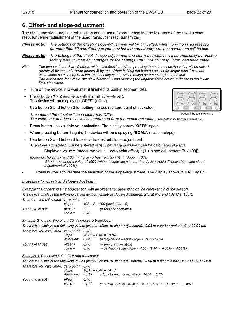
- Turn on the device and wait after it finished its built-in segment test.
- Press button 3 > 2 sec. (e.g. with a small screwdriver). The device will be displaying „OFFS“ (offset).
- Use button 2 and button 3 for setting the desired zero point offset-value.
The input of the offset will be in digit resp. °C/°F. The value that had been set will be subtracted from the measured value. (see below for further information)
- Press button 1 to validate your selection. The display shows “OFFS“ again.
- When pressing button 1 again, the device will be displaying “SCAL“. (scale = slope)
- Use button 2 and button 3 to select the desired slope-adjustment. The slope adjustment will be entered in %. The value displayed can be calculated like this:
Displayed value = (measured value – zero point offset) * (1 + slope adjustment [% / 100]). Example:The setting is 2.00 => the slope has risen 2.00% => slope = 102%.
When measuring a value of 1000 (without slope-adjustment) the device would display 1020 (with slope adjustment of 102%)
- Press button 1 to validate the selection of the slope-adjustment. The display shows “SCAL“ again.
Examples for offset- and slope-adjustment:
Example 1: Connecting a Pt1000-sensor (with an offset error depending on the cable-length of the sensor) The device displays the following values (without offset- or slope-adjustment): 2°C at 0°C and 102°C at 100°C Therefore you calculated: zero point: 2 slope: 102 – 2 = 100 (deviation = 0) You have to set: offset = 2 (= zero point-deviation) scale = 0.00
Example 2: Connecting of a 4-20mA-pressure-transducer The device displays the following values (without offset- or slope-adjustment): 0.08 at 0.00 bar and 20.02 at 20.00 bar Therefore you calculated: zero point: 0.08 slope: 20.02 – 0.08 = 19.94 deviation: 0.06 (= target-slope – actual-slope = 20.00 - 19.94) You have to set: offset = 0.08 (= zero point-deviation) scale = 0.30 (= deviation / actual-slope = 0.06 / 19.94 = 0.0030 = 0.30% )
Example 3: Connecting of a flow-rate-transducer The device displays the following values (without offset- or slope-adjustment): 0.00 at 0.00 l/min and 16.17 at 16.00 l/min Therefore you calculated: zero point: 0.00 slope: 16.17 – 0.00 = 16.17 deviation: - 0.17 (=target-slope – actual slope = 16.00 - 16.17) You have to set: offset = 0.00 scale = - 1.05 (= deviation / actual-slope = - 0.17 / 16.17 = - 0.0105 = - 1.05% )
Button 1 Button 2 Button 3
3/2018 Manual for connection and operation of the EV-94 EB page 24 of 28
7. Min-/max-value storage: The device features a minimum/maximum-value storage. In this storage the highest resp. lowest performance data is saved. Calling of the minimum-value press button 3 shortly the device will display “Lo“ briefly, after that
the min-value is displayed for about 2 sec. Calling of the maximum-value press button 2 shortly the device will display “Hi“ briefly, after that
the max-value is displayed for about 2 sec. Erasing of the min/max values press button 2 and 3 for 2 sec. The device will display “CLr“ briefly, after
that the min/max-values are set to the current displayed value.
8. Serial interface: The device features one EASYBUS-Interface. You can use the device as a full function EASYBUS-device. The serial interface allows the device to communicate with a host computer. Data polling and data transfer is done in master/slave mode, so the device will only send data on demand. Every device has a unique ID-number that makes exact identification of each device possible. With the help of a software (like EbxKonfig – freeware version available via internet) you are able to reassign an address to the device.
Additional accessories needed for the interface mode:
- Level converter EASYBUS ó PC: e.g. EBW1, EBW64, EB2000MC
- Software for communication with the device
EBS20M: 9-channel-software for displaying a measured value.
EASYCONTROL: multi-channel software for real-time-recording and displaying measure-values of a device in ACCESS®-database-format.
EASYBUS-DLL: EASYBUS-developer-package for developing own software. This package features a universal WINDOWS®-Library with documentation and program-examples. The DLL can be used in any usual programming language.
9. Error codes When detecting an operating state which is not permissible, the device will display an error code
The following error codes are defined:
Err.1: Exceeding of the measuring range Indicates that the valid measuring range of the device has been exceeded.
Possible causes: - Input signal to high. - Sensor broken (Pt100 and Pt1000). - Sensor shorted (0(4)-20mA). - Counter overflow.
Remedies: - The error-message will be reset if the input signal is within the limits. - check sensor, transducer resp. transmitter. - check device configuration (e.g. input signal) - reset the counter.
Err.2: Values below the measuring range Indicates that the values are below the valid measuring range of the device.
Possible causes: - Input signal is to low resp. negative. - Current below 4mA. - Sensor shorted (Pt100 and Pt1000). - Sensor broken (4-20mA). - Counter underflow.
Remedies: - The error-message will be reset if the input signal is within the limits. - Check sensor, transducer resp. transmitter. - check device configuration (e.g. input signal) - Reset the counter.
3/2018 Manual for connection and operation of the EV-94 EB page 25 of 28
Err.3: Display range has been exceeded Indicates that the valid display range (9999 digit) of the device has been exceeded.
Possible causes: - Incorrect scale. - Counter overflow.
Remedies: - The error-message will be reset if the display value is below 9999. - Reset the counter. - When happening frequently, check the scale-setting, maybe it was set too high and should be reduced.
Err.4: Values below display range Indicates that display value is below the valid display range of the device (-1999 digit).
Possible causes: - Incorrect scale. - Counter underflow.
Remedies: - The error-message will be reset if the display value is above -1999. - Reset the counter – When happening frequently, check the scale-setting, maybe it was set too low and should be increased.
Err.7: System-error The device features an integrated self-diagnostic-function which checks essential parts of the device permanently. When detecting a failure, error-message Err.7 will be displayed.
Possible causes: - Valid operating temperature range has been exceeded resp. is below the valid temperature range. - Device defective.
Remedies: - Stay within valid temperature range. - Exchange the defective device.
Err.9: Sensor defective The device features an integrated diagnostic-function for the connected sensor resp. transmitter. When detecting a failure, error-message Err.9 will be displayed.
Possible causes: - Sensor broken resp. sensor shorted (Pt100 or Pt1000). - Sensor broken (thermo-elements).
Remedies: - Check sensor resp. exchange defective sensor.
Er.11: Value could not be calculated Indicates a measuring value, needed for calculation of the display value, is faulty resp. out of range.
Possible causes: - Incorrect scale.
Remedies: - Check settings and input signal.
3/2018 Manual for connection and operation of the EV-94 EB page 26 of 28
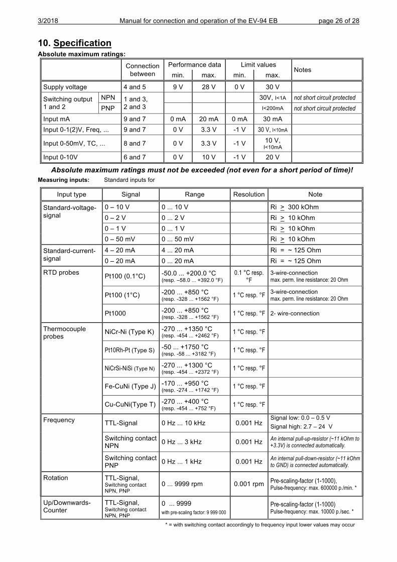
10. Specification Absolute maximum ratings:
Connection between
Performance data Limit values Notes
min. max. min. max.
Supply voltage 4 and 5 9 V 28 V 0 V 30 V
Switching output 1 and 2
NPN 1 and 3, 2 and 3
30V, I<1A not short circuit protected
PNP I<200mA not short circuit protected Input mA 9 and 7 0 mA 20 mA 0 mA 30 mA Input 0-1(2)V, Freq, ... 9 and 7 0 V 3.3 V -1 V 30 V, I<10mA
Input 0-50mV, TC, ... 8 and 7 0 V 3.3 V -1 V 10 V, I<10mA
Input 0-10V 6 and 7 0 V 10 V -1 V 20 V
Absolute maximum ratings must not be exceeded (not even for a short period of time)! Measuring inputs: Standard inputs for
Input type Signal Range Resolution Note
Standard-voltage-signal
0 – 10 V 0 ... 10 V Ri > 300 kOhm 0 – 2 V 0 ... 2 V Ri > 10 kOhm 0 – 1 V 0 ... 1 V Ri > 10 kOhm 0 – 50 mV 0 ... 50 mV Ri > 10 kOhm
Standard-current-signal
4 – 20 mA 4 ... 20 mA Ri = ~ 125 Ohm 0 – 20 mA 0 ... 20 mA Ri = ~ 125 Ohm
RTD probes Pt100 (0.1°C) -50.0 ... +200.0 °C (resp. –58.0 ... +392.0 °F)
0.1 °C resp. °F
3-wire-connection max. perm. line resistance: 20 Ohm
Pt100 (1°C) -200 ... +850 °C (resp. -328 ... +1562 °F) 1 °C resp. °F 3-wire-connection
max. perm. line resistance: 20 Ohm
Pt1000 -200 ... +850 °C (resp. -328 ... +1562 °F) 1 °C resp. °F 2- wire-connection
Thermocouple probes
NiCr-Ni (Type K) -270 ... +1350 °C (resp. -454 ... +2462 °F) 1 °C resp. °F
Pt10Rh-Pt (Type S) -50 ... +1750 °C (resp. -58 ... +3182 °F) 1 °C resp. °F
NiCrSi-NiSi (Type N) -270 ... +1300 °C (resp. -454 ... +2372 °F) 1 °C resp. °F
Fe-CuNi (Type J) -170 ... +950 °C (resp. -274 ... +1742 °F) 1 °C resp. °F
Cu-CuNi(Type T) -270 ... +400 °C (resp. -454 ... +752 °F) 1 °C resp. °F
Frequency TTL-Signal 0 Hz ... 10 kHz 0.001 Hz Signal low: 0.0 – 0.5 V Signal high: 2.7 – 24 V
Switching contact NPN 0 Hz ... 3 kHz 0.001 Hz An internal pull-up-resistor (~11 kOhm to
+3.3V) is connected automatically.
Switching contact PNP 0 Hz ... 1 kHz 0.001 Hz An internal pull-down-resistor (~11 kOhm
to GND) is connected automatically.
Rotation TTL-Signal, Switching contact NPN, PNP
0 ... 9999 rpm 0.001 rpm Pre-scaling-factor (1-1000), Pulse-frequency: max. 600000 p./min. *
Up/Downwards- Counter
TTL-Signal, Switching contact NPN, PNP
0 ... 9999 with pre-scaling factor: 9 999 000 Pre-scaling-factor (1-1000)
Pulse-frequency: max. 10000 p./sec. *
* = with switching contact accordingly to frequency input lower values may occur
3/2018 Manual for connection and operation of the EV-94 EB page 27 of 28
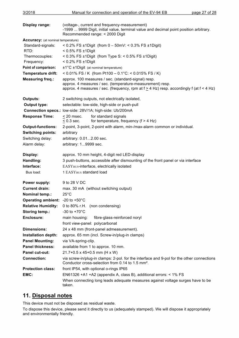
Display range: (voltage-, current and frequency-measurement) -1999 ... 9999 Digit, initial value, terminal value and decimal point position arbitrary. Recommended range: < 2000 Digit
Accuracy: (at nominal temperature) Standard-signals: < 0.2% FS ±1Digit (from 0 – 50mV: < 0.3% FS ±1Digit) RTD: < 0.5% FS ±1Digit Thermocouples: < 0.3% FS ±1Digit (from Type S: < 0.5% FS ±1Digit) Frequency: < 0.2% FS ±1Digit Point of comparison: ±1°C ±1Digit (at nominal temperature) Temperature drift: < 0.01% FS / K (from Pt100 – 0.1°C: < 0.015% FS / K) Measuring freq.: approx. 100 measures / sec. (standard-signal) resp.
approx. 4 measures / sec. (temperature-measurement) resp. approx. 4 measures / sec. (frequency, rpm at f > 4 Hz) resp. accordingly f (at f < 4 Hz)
Outputs: 2 switching outputs, not electrically isolated, Output type: selectable: low-side, high-side or push-pull Connection specs.: low-side: 28V/1A; high-side: Ub/200mA Response Time: < 20 msec. for standard signals
< 0.3 sec. for temperature, frequency (f > 4 Hz) Output-functions: 2-point, 3-point, 2-point with alarm, min-/max-alarm common or individual. Switching points: arbitrary Switching delay: arbitrary: 0.01...2.00 sec. Alarm delay: arbitrary: 1...9999 sec. Display: approx. 10 mm height, 4-digit red LED-display Handling: 3 push-buttons, accessible after dismounting of the front panel or via interface Interface: EASYBUS-interface, electrically isolated Bus load: 1 EASYBUS standard load Power supply: 9 to 28 V DC Current drain: max. 30 mA (without switching output) Nominal temp.: 25°C Operating ambient: -20 to +50°C Relative Humidity: 0 to 80% r.H. (non condensing) Storing temp.: -30 to +70°C Enclosure: main housing: fibre-glass-reinforced noryl front view-panel: polycarbonat Dimensions: 24 x 48 mm (front-panel admeasurement). Installation depth: approx. 65 mm (incl. Screw-in/plug-in clamps) Panel Mounting: via VA-spring-clip. Panel thickness: available from 1 to approx. 10 mm. Panel cut-out: 21.7+0.5 x 45+0.5 mm (H x W) Connection: via screw-in/plug-in clamps: 2-pol. for the interface and 9-pol for the other connections
Conductor cross-selection from 0.14 to 1.5 mm². Protection class: front IP54, with optional o-rings IP65 EMC: EN61326 +A1 +A2 (appendix A, class B), additional errors: < 1% FS When connecting long leads adequate measures against voltage surges have to be
taken.
11. Disposal notes This device must not be disposed as residual waste. To dispose this device, please send it directly to us (adequately stamped). We will dispose it appropriately and environmentally friendly.
button 1 button 2 button 3
Short Form Manual EV-94 EB
This short form manual allows a quick basic configuration. For more details
please refer to the "Manual for connection and operation of the EV-94 B".
Note: If no key is pressed for 30 seconds, the configuration must be reset!
� Action Display Comment Example
� Start-up by connection to current voltage xxx.... Depending on configuration Err.x, 0, xxx
� Press button 2 for > 2 Sekunden Hi, ..x.. Inp Input signal
� Press button 2 or 3 U, I, t.rES usw. I for current signal (0..20mA, 4..20mA) I (for current measurement)
� “ button 1 InP Acknowledgement of input signal
� “ button 1 SEnS Signal
� “ button 2 or 3 4..20, 0..20 Select signal 4..20 ( for 4..20mA)
� “ button 1 SEnS Acknowledge signal
� Press button 1 dp Select position of decimal point
� “ button 2 or 3 - - - - Select position of decimal point i.e. -. - - -� “ button 1 dp Acknowledge position of decimal point
� “ button 1 di.Lo Low input value (Display Low)
� “ button 2 or 3 0000 Select low input value 0.000
� “ button 1 di.Lo Acknowledge low input value
� “ button 1 di.Hi High input value (Display High)
� “ button 2 or 3 2.500 Select high input value 2.500
� “ button 1 di.Hi Acknowledge high input value
� Press button 1 Li Measuring range limit (Limit)
� “ button 2 or 3 off, on.Er, on.rG Select measuring range limit off
� “ button 1 Li Acknowledge measuring range limit
� “ button 1 FiLt Filter (Filter value 0.01 ...2.00 seconds)
� “ button 2 or 3 0.00 Select filter 1.00
� “ button 1 FiLt Acknowledge filter
� Press button 1 outP Output (switching point, configuration)
� “ button 2 or 3 2P Select output, 2-level 2P
� “ button 1 outP Acknowledge output
� “ button 1 1.dEL Delay (switching output 1, delay)
� “ button 2 or 3 1.00 Select delay 1.00
� “ button 1 1.dEL Acknowledge delay
� Press button 1 1.out Type switching output (NPN, PNP, R+)
� “ button 2 or 3 nPn, PnP, Pu.Pu Select switching output type nPn
� “ button 1 1.out Acknowledge switching output type
� “ button 1 1.Err Switching output if error (active, inactive)
� “ button 2 or 3 off, on Select switching output if error off
� “ button 1 1.Err Acknowledge switching output if error
� Press button 1 1.on Switching output 1, On
� “ button 2 or 3 0000 Switching output 1 On > = 0.505 0.505
� “ button 1 1.on Acknowledge switching output 1
� “ button 1 1.oFF Switching output 1, Off
� “ button 2 or 3 0000 Switching output 1 < = 0.495 0.495
� “ button 1 1.oFF Acknowledge switching output 1
� “ button 1 1.oFF End
KELLER AG für Druckmesstechnik St. Gallerstrasse 119 CH-8404 Winterthur www.keller-druck.com


![How Deep Is Your Love - dreamusic7.web.fc2.com€¦ · Eb AhAAhhAh Eb maj7 Eb 6 Eb maj7 5 AAhhAh Eb Eb maj7 Eb 6 [M2] Fm7/Bb IIII know knowknow your your 9 Eb Gm7 eyesineyes iinninthe](https://img.pdfslide.net/doc/110x75/5f82817213abe7470b0fcd74/how-deep-is-your-love-eb-ahaahhah-eb-maj7-eb-6-eb-maj7-5-aahhah-eb-eb-maj7-eb.jpg)