Embed Size (px)
Citation preview

User Manual Please read the Important Notice and Warnings at the end of this document Revision 1.0
www.infineon.com page 1 of 37 2018-09-04
AN2018-21 EVAL-M1-CTF610N3 User Manual
EVAL-M1-CTF610N3 User Manual
iMOTION™ Modular Application Design Kit
About this document
Scope and purpose
This user manual provides an overview of the evaluation board EVAL-M1-CTF610N3 including its main features,
key data, pin assignments and mechanical dimensions.
EVAL-M1-CTF610N3 is an evaluation board as part of the iMOTION™ Modular Application Design Kit. This power
board including a 3-phase CIPOS™ Tiny Intelligent Power Module (IPM) for motor drive application. In
combination with the control board equipped with the M1 20pin interface connector such as EVAL-M1-101T, it
features and demonstrates Infineon’s CIPOS™ Tiny IPM technology and Advanced Motion Control Engine (MCE
2.0) technology for permanent magnet motors drive over the full speed range.
This evaluation board EVAL-M1-CTF610N3 was developed to support customers during their first steps
designing applications with CIPOS™ Tiny IPM and running any permanent magnet motor via sensorless
sinusoidal control.
Intended audience
This user manual is intended for all technical specialists who know motor control and high power electronics
converter and this board is intended to be used under laboratory conditions.
Table of contents
About this document ....................................................................................................................... 1
Table of contents ............................................................................................................................ 1
1 Safety precautions ................................................................................................................. 3
2 Introduction .......................................................................................................................... 4
3 EVAL-M1-CTF610N3 main features ............................................................................................ 6
3.1 EVAL-M1-CTF610N3 board specifications ............................................................................................... 7
3.2 Pin assignment ........................................................................................................................................ 9
4 Getting Started with EVAL-M1-CTF610N3 ................................................................................. 11
4.1 Setting up the system............................................................................................................................ 11
4.2 iMOTION™ development tools and software ....................................................................................... 13
4.2.1 MCEWizard setup overview .............................................................................................................. 13
4.2.2 MCEDesigner setup overview .......................................................................................................... 15
5 Hardware description of EVAL-M1-CTF610N3 ............................................................................ 17
5.1 Inverter section using CIPOS™ Tiny IPM ............................................................................................... 17
5.1.1 DC bus sensing and MCEWizard configuration ............................................................................... 18
5.1.2 Motor External Current feedback configuration and calculation .................................................. 19
5.1.3 Inverter Overcurrent protection and Motor Gatekill configuration ............................................... 21
5.2 Thermistor/NTC Characteristics and protection calculation .............................................................. 22
5.2.1 CIPOS™ Internal NTC – Thermistor Characteristics ........................................................................ 22
5.2.2 Overtemperature Hardware Protection Circuit .............................................................................. 23
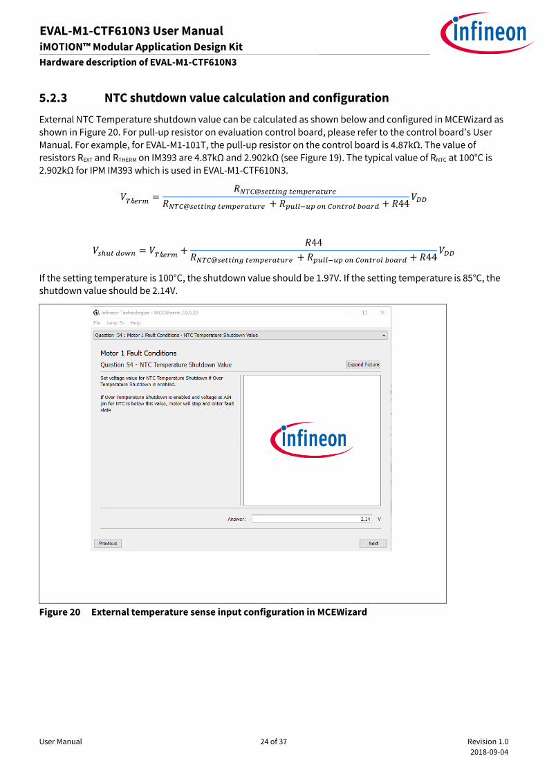
5.2.3 NTC shutdown value calculation and configuration ...................................................................... 24
5.3 Auxiliary power supply .......................................................................................................................... 25

User Manual 2 of 37 Revision 1.0
2018-09-04
EVAL-M1-CTF610N3 User Manual iMOTION™ Modular Application Design Kit
Table of contents
5.4 Schematics for EVAL-M1-CTF610N3 ...................................................................................................... 26
5.5 PCB Layout for EVAL-M1-CTF610N3 ...................................................................................................... 28
6 Reference ............................................................................................................................. 35
Revision history............................................................................................................................. 36

User Manual 3 of 37 Revision 1.0
2018-09-04
EVAL-M1-CTF610N3 User Manual iMOTION™ Modular Application Design Kit
Safety precautions
1 Safety precautions
In addition to the precautions listed throughout this manual, please read and understand the following
statements regarding hazards associated with development systems.
Table 1 Precautions
Attention: The ground potential of the EVAL-M1-CTF610N3 system is biased to a negative
DC bus voltage potential. When measuring voltage waveform by oscilloscope, the scope’s
ground needs to be isolated. Failure to do so may result in personal injury or death and
equipment damage.
Attention: Only personnel familiar with the drive and associated machinery should plan
or implement the installation, start-up and subsequent maintenance of the system.
Failure to comply may result in personal injury and/or equipment damage.
Attention: The surfaces of the drive may become hot, which may cause injury.
Attention: EVAL-M1-CTF610N3 system contains parts and assemblies sensitive to
Electrostatic Discharge (ESD). Electrostatic control precautions are required when
installing, testing, servicing or repairing this assembly. Component damage may result if
ESD control procedures are not followed. If you are not familiar with electrostatic control
procedures, refer to applicable ESD protection handbooks and guidelines.
Attention: A drive, incorrectly applied or installed, can result in component damage or
reduction in product lifetime. Wiring or application errors such as under sizing the motor,
supplying an incorrect or inadequate DC supply or excessive ambient temperatures may
result in system malfunction.
Attention: Remove or connect the control board from or to the power drive. Wait three
minutes after removing power from the power drive to discharge the bus capacitors. Do
not attempt to service the drive until the bus capacitors have discharged to zero. Failure
to do so may result in personal injury or death.
Attention: EVAL-M1-CTF610N3 system is shipped with packing materials that need to be
removed prior to installation. Failure to remove all packing materials which are
unnecessary for system installation may result in overheating or abnormal operating
condition.

User Manual 4 of 37 Revision 1.0
2018-09-04
EVAL-M1-CTF610N3 User Manual iMOTION™ Modular Application Design Kit
Introduction
2 Introduction
The EVAL-M1-CTF610N3 evaluation power board is a part of the iMOTION™ Modular Application Design Kit for
motor drives (iMOTION™ MADK). In order to run a motor, the matching control board is required to interface
this power board.
The MADK platform is intended to use various power stages with different control boards. These boards can
easily be interfaced through the 20-pin iMOTION™ MADK M1 such as Eval-M1-101Tconnector to control board.
This board is equipped with 20-pin M1 connector and is intended for single motor control only.
This evaluation board is designed to give Easy-to-use power stage based on the Infineon's CIPOS™ Tiny
Inteligent Power Module (IPM). The board is equipped with all assembly groups for sensorless field oriented
control (FOC). It provides a single-phase AC-connector, rectifier and 3-phase output for connecting the motor.
The power stage also contains emitter shunts for current sensing and a voltage divider for DC-link voltage
measurement.
The EVAL-M1-CTF610N3 evaluation board has perfect compatibility, it is compatible with the DIP and SIP two
kind of packaging form and compatible with the different level of power CIPOS™ Tiny IPM. For example, if you
need to evaluate IM393-S6E/F, The evaluation board fully support to pin-to-pin assembly and power rating.but
if you need to evaluate IM393-L6E/F or IM393-X6E/F Tiny IPM, you can only do function test evaluation and the
power rating isn’t satisfied.
The EVAL-M1-CTF610N3 evaluation board is available through regular Infineon distribution partners as well as
on Infineon's website. The features of this board are described in the main features chapter of this document,
whereas the remaining paragraphs provide information to enable the customers to copy, modify and qualify
the design for production according to their own specific requirements.
Environmental conditions were considered in the design of the EVAL-M1-CTF610N3, but it is not qualified
regarding safety requirements or manufacturing and operation over the whole operating temperature range or
lifetime. The boards provided by Infineon are subject to functional testing only.
The block diagram of the EVAL-M1-CTF610N3 is depicted in Figure 1. This evaluation board includes an EMI
filter and soft power up circuit, 20 pins iMOTION™ MADK-M1 interface connector, auxiliary power supply to
provide 15V and 3.3V and the CIPOS™ Tiny IPM.
MHVIC
20 pin iMOTIONTM
MADK-M1 connector
CIPOSTM Tiny IM393-M6F Inverter Section
Line
Neutral
15V
PW
M
RFE
Itrip
PWM
VTH
GK
DC
Bse
nse
15V
& 3
.3V
Overcurrent and Overtemperature
protection
Power Supply
I_Shunt+
I_Shunt-
EMI Filter & Soft
Power Up Circuit
Figure 1 The Block Diagram of the EVAL-M1-CTF610N3

User Manual 5 of 37 Revision 1.0
2018-09-04
EVAL-M1-CTF610N3 User Manual iMOTION™ Modular Application Design Kit
Introduction
The hardware circuit regarding overtemperature and overcurrent protection is also included in this power
board. The sense connection to open emitter shunt resistor is connected to the 20 pins iMOTION™ MADK-M1
interface connector. This power board is compatible with 2 packages(DIP and SIP) of CIPOS™ Tiny IPMs that
feature Integrated Power Hybrid IC with Open Emitter pins and built-in high precision temperature monitor and
over-current protection feature, along with the short-circuit rated IGBTs and integrated under-voltage lockout
function, deliver high level of protection and fail-safe operation.
Evaluation boards are not subject to the same procedures as regular products regarding Returned Material
Analysis (RMA), Process Change Notification (PCN) and Product Discontinuation (PD). Evaluation boards are
intended to be used under laboratory conditions by technical specialists only.

User Manual 6 of 37 Revision 1.0
2018-09-04
EVAL-M1-CTF610N3 User Manual iMOTION™ Modular Application Design Kit
EVAL-M1-CTF610N3 main features
3 EVAL-M1-CTF610N3 main features
EVAL-M1-CTF610N3 is an evaluation board for motor drive applications with 3 phase IPM. Combined in a kit
with one of the available MADK control board options, it demonstrates Infineon’s motion control IC and IPM
technology for motor drives.
Main features of CIPOS™ Tiny IPM IM393-M6F are:
• Integrated gate drivers and bootstrap function
• Temperature monitor
• Protection shutdown pin
• Low VCE(on) Trench IGBT technology
• Under voltage lockout for all channels
• Matched propagation delay for all channels
• 3.3V Schmitt-triggered input logic
• Cross-conduction prevention logic
• Isolation 2000VRMS min and CTI>600
• Recognized by UL(Pending)
The evaluation board characteristics are:
• Input voltage 160~265VAC
• Maximum 600W motor power output
• Compatble with DIP and SIP
• On board EMI filter
• Current sensing with single shunt or leg shunt
• Auxiliary power supply with 15V, 3.3V
• Overcurrent protection
• Overtemperature hardware protection
• Sensing of DC-link voltage
• Thermistor output
• Fault diagnostic output
• Measurement test-points compatible to standard oscilloscope probes
• PCB is 100 mm × 123 mm and has two layers with 35μm copper each
• RoHS complaint

User Manual 7 of 37 Revision 1.0
2018-09-04
EVAL-M1-CTF610N3 User Manual iMOTION™ Modular Application Design Kit
EVAL-M1-CTF610N3 main features
3.1 EVAL-M1-CTF610N3 board specifications
Table 2 depicts the important specifications of the evaluation board EVAL-M1-CTF610N3.
Table 2 EVAL-M1-CTF610N3 board specifications
Parameters Values Conditions / comments
Input
Voltage 165 - 265 Vrms lower AC input, less motor power output
Input current 3.2Arms input 220 VAC, Ta=25°C, IM393
Output
Power (3phases) 600 W input 220VAC, fPWM=6 kHz, Ta=25°C, Th=70°C
Current per leg 5.1Arms input 220VAC , fPWM=6 kHz, Ta=25°C, Th=70°C
DC Bus Voltage
Maximum DC bus voltage 420 V
Minimum DC bus voltage 120 V
Switching Frequency
Inverter switching frequency
fPWM
20 kHz (max)
Current feedback
Inverter current sensing resistor
RS3,RS4,RS5
100 mΩ
Protections
Output current trip level 16.6 Apeak Configured by changing pull up resistor R37.
Temperature trip level 100 °C For controller board Eval-M1-101T
On board power supply
15 V 15 V ± 2 %, max. 500 mA Used for CIPOS™ IPM gate driver and LDO
3.3 V 3.3 V ± 1 %, max. 300 mA Supplying the 3.3V to the controller board and
protection circuits
PCB characteristics
Material FR4, 1.6mm thickness, 2
layers.
35 µm copper thickness
Dimension 100 mm x 123 mm
System environment
Ambient temperature From 0 to 50°C Non-condensing, maximum RH of 95 %
1 For iMOTION™ IC IMC1xx, there are three types of Gatekill Input Source (Refer to section 5.1.3 or control board user manual for
detail). Please note that, if select comparator for Gatakill Input Source, the external Gatakill signal will be not used. And the leg
I_Shunt will be compared by the internal comparator with the “Gatekill Comparator Reference” value set in MCEWizard only.

User Manual 8 of 37 Revision 1.0
2018-09-04
EVAL-M1-CTF610N3 User Manual iMOTION™ Modular Application Design Kit
EVAL-M1-CTF610N3 main features
Figure 2 points out the functional groups on the top side of the EVAL-M1-CTF610N3 evaluation board.
Figure 2 Functional groups of the EVAL-M1-CTF610N3 evaluation board’s top side
1. J1 - AC Input connector
2. FUSE and EMI Filter
3. NTC and Rectifier Bridge
4. J3 - Motor phase connector
5. T1-Auxiliary power supply
transfomer
6. J2 - 20 pin iMOTION™
MADK-M1 interface
connector for controller
board
7. Current sensing shunt
resistor RS3, RS4, RS5
8. CIPOS™ Tiny IPM U7 (SIP)
or U6 (DIP)
1
2 3
4
5
6
7
8
User Manual 9 of 37 Revision 1.0
2018-09-04
EVAL-M1-CTF610N3 User Manual iMOTION™ Modular Application Design Kit
EVAL-M1-CTF610N3 main features
Figure 3 points out the functional groups on the bottom side of the EVAL-M1-CTF610N3 evaluation board.
Figure 3 Functional groups of the EVAL-M1-CTF610N3 evaluation board’s bottom side
3.2 Pin assignment
General information about the connectors of the EVAL-M1-CTF610N3 evaluation board is reported. Table 3
includes the details of the AC input connector J1.
Table 3 J1- AC Line connector
S. No. Pin Details
1 Line AC line input
2 Neutral AC neutral input
3 Earth Earth ground
Table 4 provides the pin assignments of the 20 pins iMOTION™MADK-M1 interface connector J2. This connector
is the interface to the controller board.
Table 4 J2 - iMOTION™MADK-M1 20 pin interface connector for controller board
Pin Name Pin Name Connectors
1 PWMUH 3.3 V compatible logic input for high side gate driver-Phase U
9. ICE5GR4780AG U1
10. Auxiliary power supply
Current sensing shunt
resistor RS1, RS2
11. IFX1117MEV33H U3
9
11
10

User Manual 10 of 37 Revision 1.0
2018-09-04
EVAL-M1-CTF610N3 User Manual iMOTION™ Modular Application Design Kit
EVAL-M1-CTF610N3 main features
2 GND Ground
3 PWMUL 3.3 V compatible logic input for low side gate driver-Phase U
4 GND 4 GND Ground
5 PWMVH 3.3 V compatible logic input for high side gate driver-Phase V
6 +3.3V On board 3.3 V supply
7 PWMVL 3.3 V compatible logic input for low side gate driver-Phase V
8 +3.3V On board 3.3 V supply
9 PWMWH 3.3 V compatible logic input for high side gate driver-Phase W
10 I_U Positive Current sense output
11 PWMWL 3.3 V compatible logic input for low side gate driver-Phase W
12 I_U- Negative current sense output or Ground
13 GK Gate kill signal – active low when overcurrent is detected
14 DCBSense DC bus positive voltage, scaled in 0-3.3 V range by a voltage divider
15 VTH Thermistor Output
16 I_V Positive Current sense output
17 I_V- Negative current sense output or Ground
18 I_W Positive Current sense output
19 I_W- Negative current sense output or Ground
20 VCC 15 V Power Supply
Table 5 provides the details of the motor side connector J4.
Table 5 J4- Motor side connector
S. No. Pin Details
1 U Connected to motor phase U
2 V Connected to motor phase V
3 W Connected to motor phase W

User Manual 11 of 37 Revision 1.0
2018-09-04
EVAL-M1-CTF610N3 User Manual iMOTION™ Modular Application Design Kit
Getting Started with EVAL-M1-CTF610N3
4 Getting Started with EVAL-M1-CTF610N3
In order to run the motor system, a combination of the iMOTION™ MADK power board (EVAL-M1-CTF610N3) and
the matching MADK control board is required. The iMOTION™ Software Tools MCEDesigner and MCEWizard are
also required in order to initialy setup the system, as well as to control and fine-tune the system performance
to match users exact needs. This chapter provides more details on setting up the system and getting started
with iMOTION™ MADK development platform.
4.1 Setting up the system
After downloading and installing the iMOTION™ PC Tools (MCEWizard and MCEDesigner), following steps needs
to be executed in order to run the motor. Refer to user manul for iMOTION™ MADK control board such as (EVAL-
M1-101T), MCEWizard and MCEDesigner documentation for more information.
Figure 4 shows the system connection using EVAL-M1-CTF610N3 and control board (used control board EVAL-
M1-101T for example).
Figure 4 System connection example using EVAL-M1-CTF610N3 and EVAL-M1-101T
1. Connect PC-USB connector on the on-board-debugger to the PC via USB cable.
2. Connect EVAL-M1-CTF610N3’s MADK M1 20-pin interface connector (J2) to control board (see Figure 4).
3. Get the latest “IMC101T-T038 MCE Software Package” available on www.infineon.com/imotion-software
web page. (Infineon iMOTION™ control IC IMC101T-T038 is used for control board EVAL-M1-101T).
4. Connect motor phase outputs to the motor.
5. Use MCEWizard to enter the motor and evaluation board hardware parameters and click button “Export to
Designer file (.txt)” to system drive parameters file which will be used by MCEDesigner.
6. Connect AC power to power input connector and power on system.
PC-USB
Connector
AC Power
Input
Motor Phase
Outputs

User Manual 12 of 37 Revision 1.0
2018-09-04
EVAL-M1-CTF610N3 User Manual iMOTION™ Modular Application Design Kit
Getting Started with EVAL-M1-CTF610N3
7. Open MCEDesigner and open MCEDesigner default configuration file (.irc) for IMC101T devices
(IMC101T_xx.irc) by clicking “File” menu and select “Open” in the pull down list.
8. Import system drive parameters file (generated in step 5) into MCEDesigner by clicking “File” > “Import Drive
Parameters”. Select “Update All” radio button.
9. Program the MCE Firmware and system parameters into the internal Flash memory of iMOTION™ IC by
clicking “Tools > Programmer “in the pull down menu, and then clicking on the “Program Firmware and
Parameter” radio button. See chapter MCEDesigner setup overview setion 4.2.2 for more details. If the latest
version of MCE firmware is already programmed into the IMC101T-T038 IC, then programming firmware can
be skipped by selecting “Program Parameters” radio button option. Finally click “Start” button to program
firware and parameter (or parameters only when programming firmware was skipped).
10. Start the motor by clicking the green traffic light button in the control bar.
User Manual 13 of 37 Revision 1.0
2018-09-04
EVAL-M1-CTF610N3 User Manual iMOTION™ Modular Application Design Kit
Getting Started with EVAL-M1-CTF610N3
4.2 iMOTION™ development tools and software
The iMOTION™Development Tool installers for MCEDesigner and MCEWizard are available for download via
Infineon iMOTIONTM website (http://www.infineon.com/imotion-software). All the available tools and software
variants are listed there.
On-board debugger uses the SEGGER J-Link’s driver for UART communication with IMC101T-T038. J-Link driver
will be installed during the MCEDesigner installation. In case the driver is not installed properly, please go to
SEGGER J-Link website to download and install the latest J-Link “Software and Documentation pack for
Windows”.
4.2.1 MCEWizard setup overview
After installing the MCEWizard, the shortcut for MCEWizard appears on the Windows desktop. Double click the
shortcut to open the MCEWizard and configure the parameters for evaluation boards or motor. Figure 6 shows
the “Welcome Page” for MCEWizard, where the MADK control board or power board can be selected through
the pull-down list. Infineon keeps releasing new MADK controller and power boards. Therefore, it could happen
that some of the newest power boards are not pre-configured in the MCEWizard tool and cannot be selected
through the pull-down menu. In that case, the user should select any other power board (as similar as possible)
and follow the MCEWizard setup steps by entering the parameter values which are specific to the chosen board.
Make sure both “I have modified the circuit board” and “Enable advanced question” checkmarks are selected.
Please refer to the User Manual of the corresponding power board for additional information.
After selecting the MADK control and the power board, start the MCEWizard system setup procedure by clicking
the “Next” button in the right bottom corner as shown in Figure 6.
Figure 5 Welcome Page of MCEWizard
iMOTION™ MADK system enables users to easily test different combination of control and power board with
their motors. User should be familiar with the system level parameters which are related to the motor used.
There are very limited numbers of parameters which are specific to the control board or power board hardware.
Table 6 provides the MCEWizard setup overview for hardware related parameters. Similar tables will be

User Manual 14 of 37 Revision 1.0
2018-09-04
EVAL-M1-CTF610N3 User Manual iMOTION™ Modular Application Design Kit
Getting Started with EVAL-M1-CTF610N3
available in each power board’s User Manual. Combination of this table and the corresponding table of the
power board provides enough information to setup the MADK-based motor drive system in shortest time.
Table 6 MCEWizard setup overview table
Page Parameter Value Comment
Welcome Page Power Board selecting MADK power board name If no, select similar
power board to modify
Options Page Motor 1 Shunt Configuration 100mΩ
Question 3 Controller Supply Voltage Refer to control board user manual
Question 19 Max DC Bus Voltage 420V
Question 23 DC Bus Sensing High Resistor 2MΩ
Question 24 DC Bus Sensing Low Resistor Refer to control board user manual 13.3kΩ by default
Question 54 NTC Temperature Shutdown
value
Calculated as the Section 5.2.3 Refer to the control
board user manual
Question 63 GateSense Low-Side Devices High is true
Question 64 GateSense High-Side Devices High is true
Question 69 Motor 1 Current Input Calculated as the Section 5.1.2
After all the MCEWizard questions are answered, the “Verify & Save Page” will be shown as in Figure 6
Figure 6 Verify and Save page for MCEWizard
Click “Calculate” button and “Export to Designer File (.txt)” button to save the parameter file which will be used
by the MCEDesigner in the next steps.

User Manual 15 of 37 Revision 1.0
2018-09-04
EVAL-M1-CTF610N3 User Manual iMOTION™ Modular Application Design Kit
Getting Started with EVAL-M1-CTF610N3
4.2.2 MCEDesigner setup overview
After installing MCEDesigner installer, there is a shortcut for MCEDesigner on Windows desktop. Double click
the shortcut to open MCEDesigner and then open “IMC101T_xx.irc” file as shown in Table 6.
Figure 7 MCEDesigner’s Main Display for EVAL-M1-101T
To program system drive parameters into IMC101T-T038, please click “Tools” menu and select “Programmer”
in the pull down list. The pop-up window “Program IMC controller” will show up as in Figure 8. Click on the
“Program Parameters” radio button (this is the default option), and then select the Drive System Parameter file
created using MCEWizard by clicking on “Browse”. Finally, click on the “Start” button to program the parameter
file into the IMC101T-T038 IC.
Figure 8 “Program IMC Controller” pop-up window
User Manual 16 of 37 Revision 1.0
2018-09-04
EVAL-M1-CTF610N3 User Manual iMOTION™ Modular Application Design Kit
Getting Started with EVAL-M1-CTF610N3
After Drive System Parameter file has been programmed into IMC102 controller, and the motor drive system is
powered, the MCEDesigner can be used to start/stop the motor, display motor current traces, change the motor
speeds, modify drive parameters and many other functions. Please refer to the MCEDesigner documentation
for more details.
Note: On-board Debugger portion of EVAL-M1-101T is galvanically isolated from the controller portion
and the attached power board. In order to program the parameters or firmware to the IMC101T-
T038 controller, the 3.3V DC voltage needs to be supplied to the controller portion of the EVAL-M1-
101T. This voltage can either be supplied by the power board (MADK power boards are designed to
supply the 3.3V to the control board through M1 connector) or by feeding the 3.3V DC voltage to the
control board through some of the available 3.3V access/test points if the power board is not
attached to the EVAL-M1-101T control board.
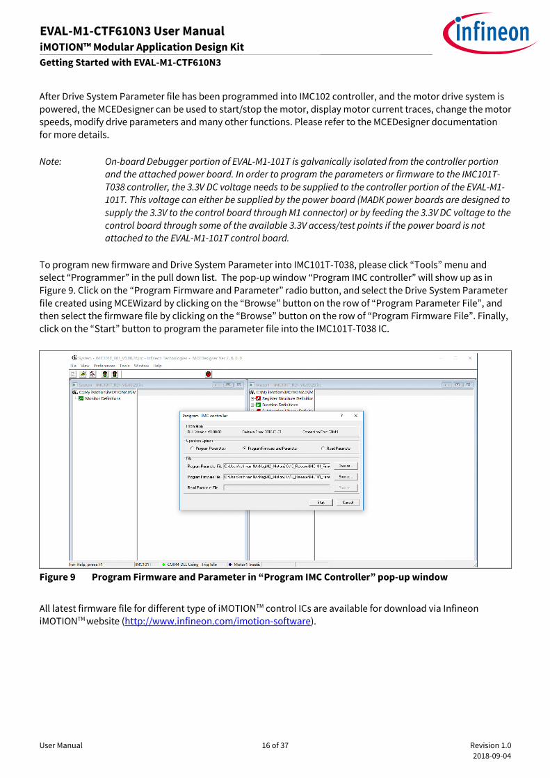
To program new firmware and Drive System Parameter into IMC101T-T038, please click “Tools” menu and
select “Programmer” in the pull down list. The pop-up window “Program IMC controller” will show up as in
Figure 9. Click on the “Program Firmware and Parameter” radio button, and select the Drive System Parameter
file created using MCEWizard by clicking on the “Browse” button on the row of “Program Parameter File”, and
then select the firmware file by clicking on the “Browse” button on the row of “Program Firmware File”. Finally,
click on the “Start” button to program the parameter file into the IMC101T-T038 IC.
Figure 9 Program Firmware and Parameter in “Program IMC Controller” pop-up window
All latest firmware file for different type of iMOTIONTM control ICs are available for download via Infineon
iMOTIONTM website (http://www.infineon.com/imotion-software).
User Manual 17 of 37 Revision 1.0
2018-09-04
EVAL-M1-CTF610N3 User Manual iMOTION™ Modular Application Design Kit
Hardware description of EVAL-M1-CTF610N3
5 Hardware description of EVAL-M1-CTF610N3
To meet individual customer requirements and make the EVAL-M1-CTF610N3 evaluation board a basis for
development or modification, all necessary technical data like schematics, layout and components are
included in this chapter.
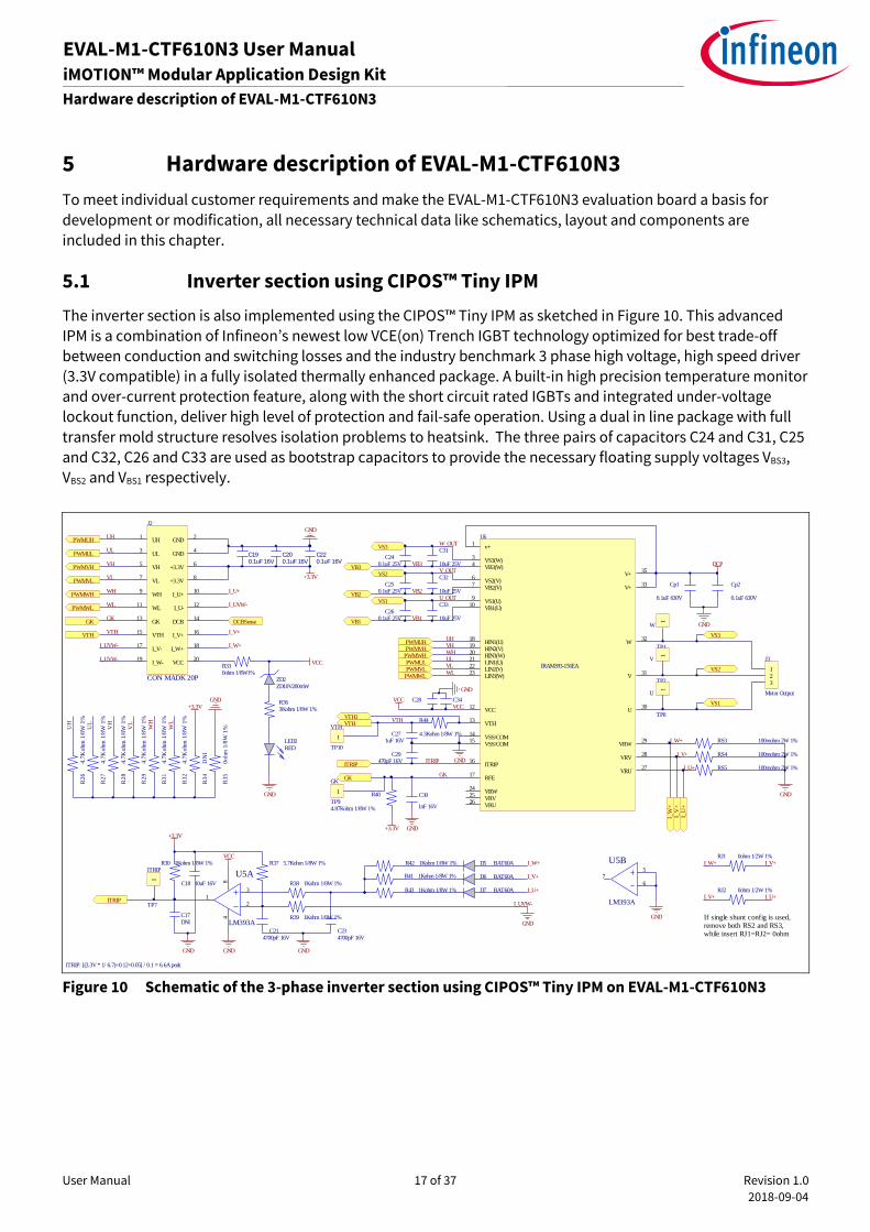
5.1 Inverter section using CIPOS™ Tiny IPM
The inverter section is also implemented using the CIPOS™ Tiny IPM as sketched in Figure 10. This advanced
IPM is a combination of Infineon’s newest low VCE(on) Trench IGBT technology optimized for best trade-off
between conduction and switching losses and the industry benchmark 3 phase high voltage, high speed driver
(3.3V compatible) in a fully isolated thermally enhanced package. A built-in high precision temperature monitor
and over-current protection feature, along with the short circuit rated IGBTs and integrated under-voltage
lockout function, deliver high level of protection and fail-safe operation. Using a dual in line package with full
transfer mold structure resolves isolation problems to heatsink. The three pairs of capacitors C24 and C31, C25
and C32, C26 and C33 are used as bootstrap capacitors to provide the necessary floating supply voltages VBS3,
VBS2 and VBS1 respectively.
Figure 10 Schematic of the 3-phase inverter section using CIPOS™ Tiny IPM on EVAL-M1-CTF610N3
VCC
ZD2ZD10V200mW
R330ohm 1/8W1%
R363Kohm 1/8W 1%
GND
C31
10uF 25V
123
J3
Motor Output
RS3 100mohm 2W 1%
RS5 100mohm 2W 1%
RS4 100mohm 2W 1%
R40
4.87Kohm 1/8W 1%
C30
1nF 16V
GK
VTH
C271uF 16V
ITRIP
v+1
VS3(W)3
VB3(W)4
VS2(V)6
VB2(V)7
VS1(U)9
VB1(U)10
VCC12
VTH13
VSS/COM14
VSS/COM15
ITRIP16
RFE17
HIN1(U)18
HIN2(V)19
HIN3(W)20
LIN1(U)21
LIN2(V)22
LIN3(W)23
VRW24
VRV25
VRU26
VRU27
VRV28
VRW29
U30
V31
W32
V+33
V+35
U6
IRAM393-156EA
R44
4.3Kohm 1/8W 1%
Cp1
0.1uF 630V
C240.1uF 25V
Cp2
0.1uF 630V
C29470pF 16V
GND
PWMUH
PWMUL
PWMVH
PWMVL
PWMWH
PWMWL
GK
VTH
DCBSense
C220.1uF 16V
C190.1uF 16V
C200.1uF 16V
+3.3V
PWMUH
PWMUL
PWMVH
PWMVL
PWMWH
PWMWL
C32
10uF 25VC25
0.1uF 25V
C33
10uF 25VC26
0.1uF 25V
C34C28VCC
GND
GND+3.3V
GND
R42 1Kohm 1/8W 1%
C214700pF 16V
C18 10uF 16V
R37 5.7Kohm 1/8W 1%
C234700pF 16V
R38 1Kohm 1/8W 1%
ITRIP
R30 1Kohm 1/8W 1%
84
3
21
U5A
LM393A
+3.3V
VCC
C17DNI
GNDGND GND
R39 1Kohm 1/8W 1%
ITRIP: [(3.3V * 1/ 6.7)+0.12+0.05] / 0.1 = 6.6A peak
D5 BAT60A
D6 BAT60A
D7 BAT60A
R41 1Kohm 1/8W 1%
R43 1Kohm 1/8W 1%
5
67
U5B
LM393A
GND
I_W
+I_
V+
I_U
+
If single shunt config is used, remove both RS2 and RS3, while insert RJ1=RJ2= 0ohm
RJ1 0ohm 1/2W 1%
RJ2 0ohm 1/2W 1%
I_W+
I_W+
I_V+
I_U+
I_W+ I_V+
I_V+
I_W+
I_V+
UH
UL
VH
VL
WH
WL
WL
UL
VHUH
WH
VL
GK
GK
VTH
VTH
ITRIP
R3
4D
NI
R3
50
ohm
1/8
W 1
%
R2
64
.7K
ohm
1/8
W 1
%
R2
74
.7K
ohm
1/8
W 1
%
R2
84
.7K
ohm
1/8
W 1
%
R2
94
.7K
ohm
1/8
W 1
%
R3
14
.7K
ohm
1/8
W 1
%
R3
24
.7K
ohm
1/8
W 1
%
UH
UL
VH
VL
WL
+3.3V
U_OUT
V_OUT
W_OUT
VB3
VB2
VB1
VCC
VTH1
VS1
VS2
VS3
VB1
VB2
VB3
VS1
VS2
VS3
GND
GND
DCP
UH1
GND2
UL3
GND4
VH5
+3.3V6
VL7
+3.3V8
WH9
I_U+10
WL11
I_U-12
GK13
DCB14
VTH15
I_V+16
I_V-17
I_W+18
I_W-19
VCC20
J2
CON MADK 20P
LED2RED
GND
GND
I_UVW-
I_UVW-
I_UVW-
I_UVW-
I_U+
I_U+
I_U+
I_V+
WH
1
W
TP1
1V
TP2
1
U
TP8
1
VTH
TP10
1
GK
TP9
1
ITRIP
TP7

User Manual 18 of 37 Revision 1.0
2018-09-04
EVAL-M1-CTF610N3 User Manual iMOTION™ Modular Application Design Kit
Hardware description of EVAL-M1-CTF610N3
5.1.1 DC bus sensing and MCEWizard configuration
Pin 14 and pin 26 of connector J3 provide access to the DC-link voltage DCBsense. Three possible feedback
cases are associated with these pins. Figure 11 provides the DC bus sense resistor details. By default, the
resistor R5 is not mounted on EVAL-M1-CTF610N3. There must be a pull-down resistor mounted on the
corresponding controller board.
Figure 11 DC bus sense resistor on EVAL-M1-CTF610N3 evaluation board
If a pull down resistor of 13.3 kΩ referred to ground is inserted either on the EVAL-M1-CTF610N3 evaluation
board or on the control board, the DCBSense voltage results in the range of 0 to 3.3 V on the pin reflecting a DC
bus voltage range of 0 to 420 V.If a pull down resistor of 13.3 kΩ is inserted on both, EVAL-M1-CTF610N3
evaluation board and on the control card, the DCBSense results scale to 0-1.65 V. No safety issue occurs. If no
feedback is desired on the DCBSense pin, R2, R3, R4 or R6 should be removed to avoid high voltage on the
connector.
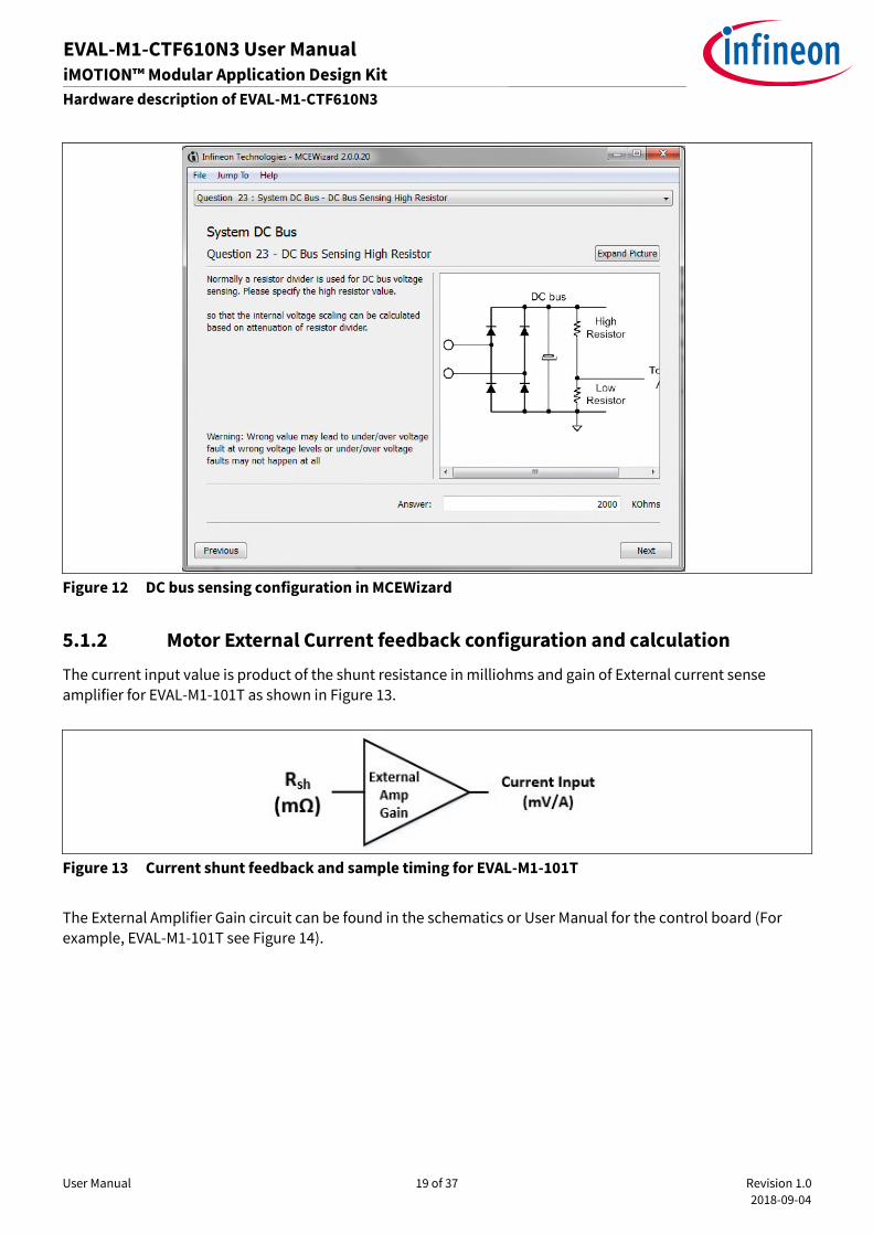
The high side resistors R2, R3, R4 and R6 for the DC bus sensing resistor divider on the controller board EVAL-
M1-CTF610N3 are 2000kΩ, and should be configured in MCEWizard as shown in Figure 12. For the low side
resistor value, please refer to the User Manual of the corresponding control board.
GN
D
R2
500K
ohm
1/8
W 1
%
R3
500K
ohm
1/8
W 1
%
R4
500K
ohm
1/8
W 1
%
R6
500K
ohm
1/8
W 1
%
R5
DN
I
DC
Bse
nse
C2
DN
I
1
DC
P
TP
3
User Manual 19 of 37 Revision 1.0
2018-09-04
EVAL-M1-CTF610N3 User Manual iMOTION™ Modular Application Design Kit
Hardware description of EVAL-M1-CTF610N3
Figure 12 DC bus sensing configuration in MCEWizard
5.1.2 Motor External Current feedback configuration and calculation
The current input value is product of the shunt resistance in milliohms and gain of External current sense
amplifier for EVAL-M1-101T as shown in Figure 13.
Figure 13 Current shunt feedback and sample timing for EVAL-M1-101T
The External Amplifier Gain circuit can be found in the schematics or User Manual for the control board (For
example, EVAL-M1-101T see Figure 14).

User Manual 20 of 37 Revision 1.0
2018-09-04
EVAL-M1-CTF610N3 User Manual iMOTION™ Modular Application Design Kit
Hardware description of EVAL-M1-CTF610N3
Figure 14 depicts IU+ current feedback sensing circuity on EVAL-M1-101T evaluation board. Please note that the
default external amplification gain is less than 1 for current sense in this evaluation board.
Figure 14 The part of Current feedback on the EVAL-M1-101T evaluation board
Based on the principle of Kirchhoff's voltage law,
≈ ≈ ( − ∗ ) ∗
+ + ∗ =
+
+
+ ∗
=
+ =
5
6
Based on this calculation, the current input for the MADK combination of EVAL-M1-101T and EVAL-M1-
CTF610N3 is 83.3 mV/A.
Please use same procedure to calculate the current input for other combinations of MADK boards and enter it
into MCEWizard as shown in Figure 15.
R72k, 1%
C15
220pFIU+
R610k, 1%
+3.3V
R8
100RIU
6
iMOTIONController
Rsh
Current shunt
resistor on power
board
V2
Ish
V1

User Manual 21 of 37 Revision 1.0
2018-09-04
EVAL-M1-CTF610N3 User Manual iMOTION™ Modular Application Design Kit
Hardware description of EVAL-M1-CTF610N3
Figure 15 Current feedback configuration in MCEWizard for EVAL-M1-101T and EVAL-M1-CTF610N3
5.1.3 Inverter Overcurrent protection and Motor Gatekill configuration
Figure 16 displays the overcurrent protection circuitry. The current sensing signal I_Shunt is connected to ITRIP
via through the comparator U5A, and ITRIP is filtered through capacitor C29.
Figure 16 Overcurrent protection circuit on the EVAL-M1-CTF610N3 evaluation board
The typical value of ITRIP positive going threshold VIT, TH+ is 490mV. So the inverter output peak current is about
6.6Apeak.
= ∗
3937 + 39
+ // +
R42 1Kohm 1/8W 1%
C214700pF 16V
C18 10uF 16V
R37 5.7Kohm 1/8W 1%
C234700pF 16V
R38 1Kohm 1/8W 1%
ITRIP
R30 1Kohm 1/8W 1%
84
3
21
U5A
LM393A
+3.3V
VCC
C17DNI
GNDGND GND
R39 1Kohm 1/8W 1%
D5 BAT60A
D6 BAT60A
D7 BAT60A
R41 1Kohm 1/8W 1%
R43 1Kohm 1/8W 1%
I_W+
I_V+
I_U+
GND
I_UVW-
1
ITRIP
TP7
User Manual 22 of 37 Revision 1.0
2018-09-04
EVAL-M1-CTF610N3 User Manual iMOTION™ Modular Application Design Kit
Hardware description of EVAL-M1-CTF610N3
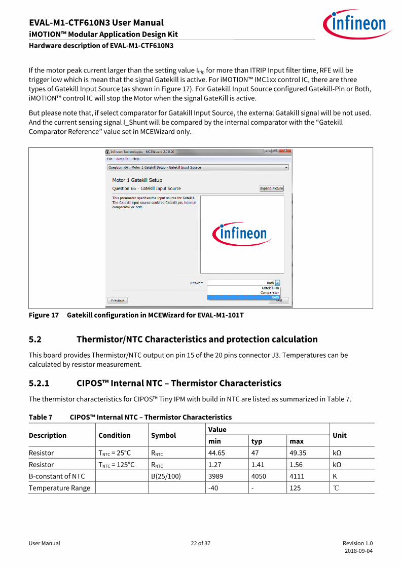
If the motor peak current larger than the setting value Itrip for more than ITRIP Input filter time, RFE will be
trigger low which is mean that the signal Gatekill is active. For iMOTION™ IMC1xx control IC, there are three
types of Gatekill Input Source (as shown in Figure 17). For Gatekill Input Source configured Gatekill-Pin or Both,
iMOTION™ control IC will stop the Motor when the signal GateKill is active.
But please note that, if select comparator for Gatakill Input Source, the external Gatakill signal will be not used.
And the current sensing signal I_Shunt will be compared by the internal comparator with the “Gatekill
Comparator Reference” value set in MCEWizard only.
Figure 17 Gatekill configuration in MCEWizard for EVAL-M1-101T
5.2 Thermistor/NTC Characteristics and protection calculation
This board provides Thermistor/NTC output on pin 15 of the 20 pins connector J3. Temperatures can be
calculated by resistor measurement.
5.2.1 CIPOS™ Internal NTC – Thermistor Characteristics
The thermistor characteristics for CIPOS™ Tiny IPM with build in NTC are listed as summarized in Table 7.
Table 7 CIPOS™ Internal NTC – Thermistor Characteristics
Description Condition Symbol Value
Unit min typ max
Resistor TNTC = 25°C RNTC 44.65 47 49.35 kΩ
Resistor TNTC = 125°C RNTC 1.27 1.41 1.56 kΩ
B-constant of NTC B(25/100) 3989 4050 4111 K
Temperature Range -40 - 125

User Manual 23 of 37 Revision 1.0
2018-09-04
EVAL-M1-CTF610N3 User Manual iMOTION™ Modular Application Design Kit
Hardware description of EVAL-M1-CTF610N3
The VTH pin of CIPOS™-Modules provides direct access to the NTC, which is referenced to VSS. An external pull-
up resistor connected to +3.3V ensures that the resulting voltage can be directly connected to the
microcontroller.
Figure 18 Thermistor readout vs.temperature(with 4.7kohm Rext pull-down resistor)and typical
thermistor resistance values vs.temperature table
5.2.2 Overtemperature Hardware Protection Circuit
In this evaluation design kits EVAL-M1-CTF610N3 and EVAL-M1-101T, the VTH pin is directly connected to the
VTH pin for controller IC IMC101T.
Figure 19 Overtemperature protection circuit schematic for EVAL-M1-CTF610N3 and EVAL-M1-101T
C271uF 16V
R444.3Kohm 1/8W 1%
VTH
1
VTHTP10
+3.3V
R24.87Kohm 1/8W 1%
C90.01uF 16V
IM393-M6EIMC-101T
13 VTHNTC 7
User Manual 24 of 37 Revision 1.0
2018-09-04
EVAL-M1-CTF610N3 User Manual iMOTION™ Modular Application Design Kit
Hardware description of EVAL-M1-CTF610N3
5.2.3 NTC shutdown value calculation and configuration
External NTC Temperature shutdown value can be calculated as shown below and configured in MCEWizard as
shown in Figure 20. For pull-up resistor on evaluation control board, please refer to the control board’s User
Manual. For example, for EVAL-M1-101T, the pull-up resistor on the control board is 4.87kΩ. The value of
resistors REXT and RTHERM on IM393 are 4.87kΩ and 2.902kΩ (see Figure 19). The typical value of RNTC at 100°C is
2.902kΩ for IPM IM393 which is used in EVAL-M1-CTF610N3.
ℎ =@
@ + + 44
= ℎ +44
@ + + 44
If the setting temperature is 100°C, the shutdown value should be 1.97V. If the setting temperature is 85°C, the
shutdown value should be 2.14V.
Figure 20 External temperature sense input configuration in MCEWizard
User Manual 25 of 37 Revision 1.0
2018-09-04
EVAL-M1-CTF610N3 User Manual iMOTION™ Modular Application Design Kit
Hardware description of EVAL-M1-CTF610N3
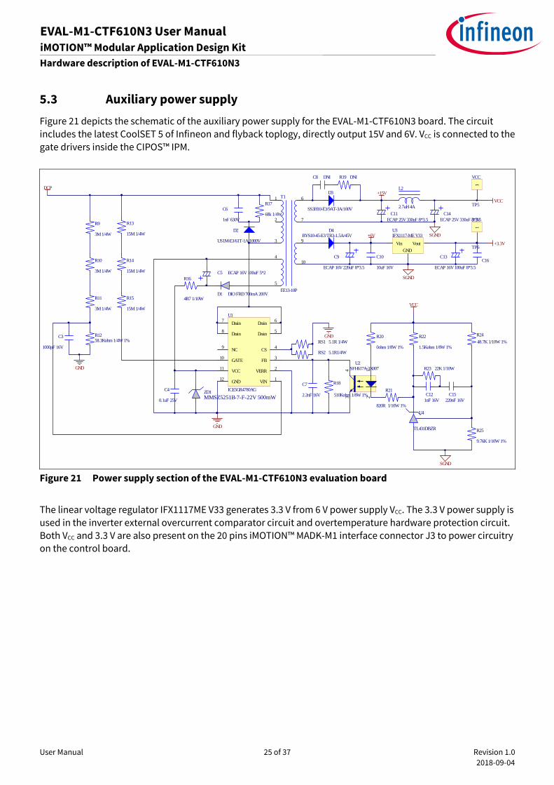
5.3 Auxiliary power supply
Figure 21 depicts the schematic of the auxiliary power supply for the EVAL-M1-CTF610N3 board. The circuit
includes the latest CoolSET 5 of Infineon and flyback toplogy, directly output 15V and 6V. VCC is connected to the
gate drivers inside the CIPOS™ IPM.
Figure 21 Power supply section of the EVAL-M1-CTF610N3 evaluation board
The linear voltage regulator IFX1117ME V33 generates 3.3 V from 6 V power supply VCC. The 3.3 V power supply is
used in the inverter external overcurrent comparator circuit and overtemperature hardware protection circuit.
Both VCC and 3.3 V are also present on the 20 pins iMOTION™ MADK-M1 interface connector J3 to power circuitry
on the control board.
123
4 SFH617A-3X007U2
Vin Vout
GND
U3IFX1117-ME V33
C13
ECAP 16V 100uF 8*3.5
C9
ECAP 16V 220uF 8*3.5
C14ECAP 25V 330uF 8*3.5
C11ECAP 25V 330uF 8*3.5
C5 ECAP 16V 100uF 5*2
C8 DNI
C10
10uF 16V
C121nF 16V
C16
C6
1nF 630V68k 1/4W
R17
15M 1/4W
R13
15M 1/4W
R14
15M 1/4W
R15 4R7 1/10W
R16
R20
0ohm 1/8W 1%48.7K 1/10W 1%
R24R22
1.5Kohm 1/8W 1%
R19 DNI
SS3H10-E3/9AT-3A/100V
D3
BYS10-45-E3/TR3-1.5A/45VD4
US1M-E3/61T-1A/1000V
D2
C7
2.2nF 16V
GND
GND
9.76K 1/10W 1%
R25
VCC
+3.3V
SGND
VCC
820R 1/10W 1%
R21C15
220nF 16V
C3
1000pF 16V
SGND
+6V
Drain6
VIN1
Drain7
NC9
GATE10
VCC11
GND12
Drain5
VERR2
FB3
CS4
Drain8
U1
ICE5GR4780AG
R1258.3Kohm 1/4W 1%
C4
0.1uF 25V
5.1R 1/4WRS1
5.1R1/4WRS2
GND
3M 1/4W
R9
3M 1/4W
R10
3M 1/4W
R11
22K 1/10WR23
+15V
SGND
1
2
3
4
5
6
7
10
9
T1
EE13-10P
DCP
ZD1MMSZ5251B-7-F-22V 500mW
D1 DIO FRD 700mA 200V
L2
2.7uH 4A
R18
510Kohm 1/8W 1%
1
VCC
TP5
1
3.3V
TP6
U4
TL431DBZR
User Manual 26 of 37 Revision 1.0
2018-09-04
EVAL-M1-CTF610N3 User Manual iMOTION™ Modular Application Design Kit
Hardware description of EVAL-M1-CTF610N3
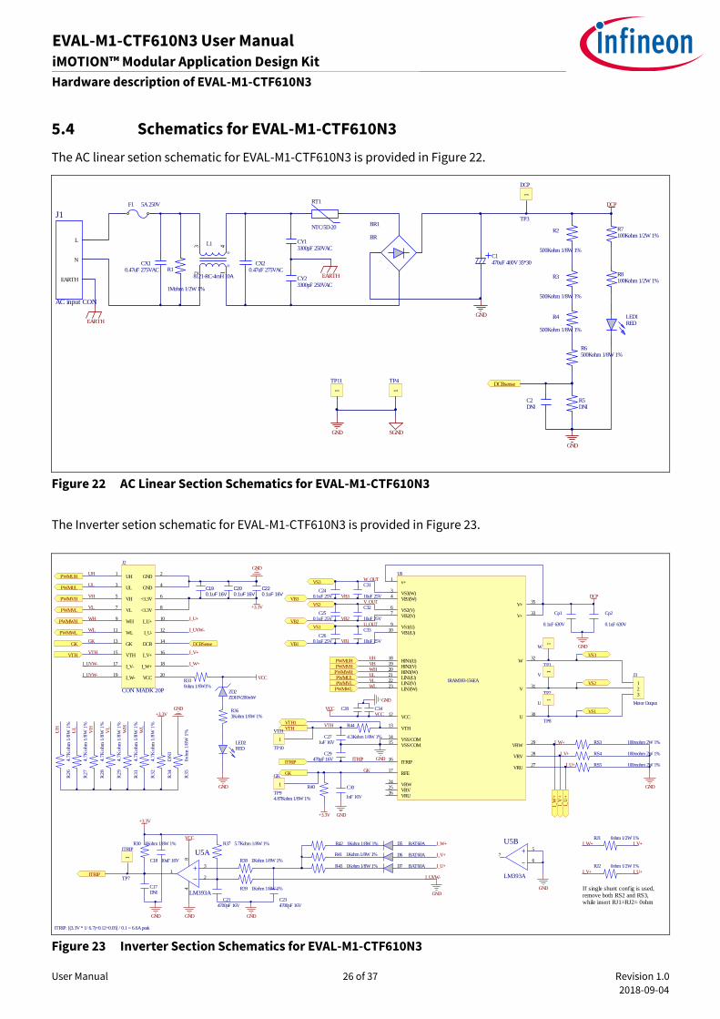
5.4 Schematics for EVAL-M1-CTF610N3
The AC linear setion schematic for EVAL-M1-CTF610N3 is provided in Figure 22.
Figure 22 AC Linear Section Schematics for EVAL-M1-CTF610N3
The Inverter setion schematic for EVAL-M1-CTF610N3 is provided in Figure 23.
Figure 23 Inverter Section Schematics for EVAL-M1-CTF610N3
CX10.47uF 275VAC R1
1Mohm 1/2W 1%
12
43 L1
8121-RC-4mH 10A
BR1
BR
CX20.47uF 275VAC
CY23300pF 250VAC
CY13300pF 250VAC
EARTH
DCP
GND
GND
R2
500Kohm 1/8W 1%
R3
500Kohm 1/8W 1%
R4
500Kohm 1/8W 1%
R6500Kohm 1/8W 1%
R5DNI
DCBsense
RT1
NTC/5D-20 R7100Kohm 1/2W 1%
R8100Kohm 1/2W 1%
C1470uF 400V 35*30
C2DNI
EARTH
F1 5A 250V
L
N
EARTH
J1
AC input CON
LED1RED
1
DCP
TP3
GND SGND
1
TP4
1
TP11
VCC
ZD2ZD10V200mW
R330ohm 1/8W1%
R363Kohm 1/8W 1%
GND
C31
10uF 25V
123
J3
Motor Output
RS3 100mohm 2W 1%
RS5 100mohm 2W 1%
RS4 100mohm 2W 1%
R40
4.87Kohm 1/8W 1%
C30
1nF 16V
GK
VTH
C271uF 16V
ITRIP
v+1
VS3(W)3
VB3(W)4
VS2(V)6
VB2(V)7
VS1(U)9
VB1(U)10
VCC12
VTH13
VSS/COM14
VSS/COM15
ITRIP16
RFE17
HIN1(U)18
HIN2(V)19
HIN3(W)20
LIN1(U)21
LIN2(V)22
LIN3(W)23
VRW24
VRV25
VRU26
VRU27
VRV28
VRW29
U30
V31
W32
V+33
V+35
U6
IRAM393-156EA
R44
4.3Kohm 1/8W 1%
Cp1
0.1uF 630V
C240.1uF 25V
Cp2
0.1uF 630V
C29470pF 16V
GND
PWMUH
PWMUL
PWMVH
PWMVL
PWMWH
PWMWL
GK
VTH
DCBSense
C220.1uF 16V
C190.1uF 16V
C200.1uF 16V
+3.3V
PWMUH
PWMUL
PWMVH
PWMVL
PWMWH
PWMWL
C32
10uF 25VC25
0.1uF 25V
C33
10uF 25VC26
0.1uF 25V
C34C28VCC
GND
GND+3.3V
GND
R42 1Kohm 1/8W 1%
C214700pF 16V
C18 10uF 16V
R37 5.7Kohm 1/8W 1%
C234700pF 16V
R38 1Kohm 1/8W 1%
ITRIP
R30 1Kohm 1/8W 1%
84
3
21
U5A
LM393A
+3.3V
VCC
C17DNI
GNDGND GND
R39 1Kohm 1/8W 1%
ITRIP: [(3.3V * 1/ 6.7)+0.12+0.05] / 0.1 = 6.6A peak
D5 BAT60A
D6 BAT60A
D7 BAT60A
R41 1Kohm 1/8W 1%
R43 1Kohm 1/8W 1%
5
67
U5B
LM393A
GND
I_W
+I_
V+
I_U
+
If single shunt config is used, remove both RS2 and RS3, while insert RJ1=RJ2= 0ohm
RJ1 0ohm 1/2W 1%
RJ2 0ohm 1/2W 1%
I_W+
I_W+
I_V+
I_U+
I_W+ I_V+
I_V+
I_W+
I_V+
UH
UL
VH
VL
WH
WL
WL
UL
VHUH
WH
VL
GK
GK
VTH
VTH
ITRIP
R3
4D
NI
R3
50
ohm
1/8
W 1
%
R2
64
.7K
ohm
1/8
W 1
%
R2
74
.7K
ohm
1/8
W 1
%
R2
84
.7K
ohm
1/8
W 1
%
R2
94
.7K
ohm
1/8
W 1
%
R3
14
.7K
ohm
1/8
W 1
%
R3
24
.7K
ohm
1/8
W 1
%
UH
UL
VH
VL
WL
+3.3V
U_OUT
V_OUT
W_OUT
VB3
VB2
VB1
VCC
VTH1
VS1
VS2
VS3
VB1
VB2
VB3
VS1
VS2
VS3
GND
GND
DCP
UH1
GND2
UL3
GND4
VH5
+3.3V6
VL7
+3.3V8
WH9
I_U+10
WL11
I_U-12
GK13
DCB14
VTH15
I_V+16
I_V-17
I_W+18
I_W-19
VCC20
J2
CON MADK 20P
LED2RED
GND
GND
I_UVW-
I_UVW-
I_UVW-
I_UVW-
I_U+
I_U+
I_U+
I_V+
WH
1
W
TP1
1
V
TP2
1
U
TP8
1
VTH
TP10
1
GK
TP9
1
ITRIP
TP7
User Manual 27 of 37 Revision 1.0
2018-09-04
EVAL-M1-CTF610N3 User Manual iMOTION™ Modular Application Design Kit
Hardware description of EVAL-M1-CTF610N3
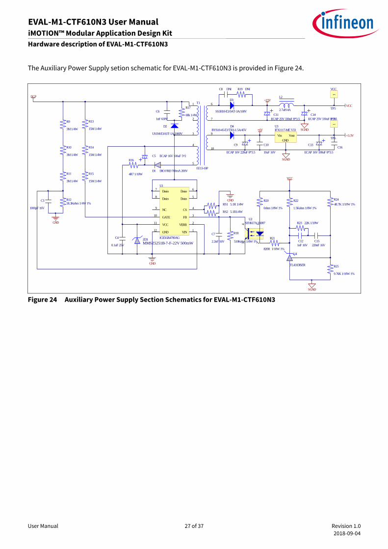
The Auxiliary Power Supply setion schematic for EVAL-M1-CTF610N3 is provided in Figure 24.
Figure 24 Auxiliary Power Supply Section Schematics for EVAL-M1-CTF610N3
123
4 SFH617A-3X007U2
Vin Vout
GND
U3IFX1117-ME V33
C13
ECAP 16V 100uF 8*3.5
C9
ECAP 16V 220uF 8*3.5
C14ECAP 25V 330uF 8*3.5
C11ECAP 25V 330uF 8*3.5
C5 ECAP 16V 100uF 5*2
C8 DNI
C10
10uF 16V
C121nF 16V
C16
C6
1nF 630V68k 1/4W
R17
15M 1/4W
R13
15M 1/4W
R14
15M 1/4W
R15 4R7 1/10W
R16
R20
0ohm 1/8W 1%48.7K 1/10W 1%
R24R22
1.5Kohm 1/8W 1%
R19 DNI
SS3H10-E3/9AT-3A/100V
D3
BYS10-45-E3/TR3-1.5A/45VD4
US1M-E3/61T-1A/1000V
D2
C7
2.2nF 16V
GND
GND
9.76K 1/10W 1%
R25
VCC
+3.3V
SGND
VCC
820R 1/10W 1%
R21C15
220nF 16V
C3
1000pF 16V
SGND
+6V
Drain6
VIN1
Drain7
NC9
GATE10
VCC11
GND12
Drain5
VERR2
FB3
CS4
Drain8
U1
ICE5GR4780AG
R1258.3Kohm 1/4W 1%
C4
0.1uF 25V
5.1R 1/4WRS1
5.1R1/4WRS2
GND
3M 1/4W
R9
3M 1/4W
R10
3M 1/4W
R11
22K 1/10WR23
+15V
SGND
1
2
3
4
5
6
7
10
9
T1
EE13-10P
DCP
ZD1MMSZ5251B-7-F-22V 500mW
D1 DIO FRD 700mA 200V
L2
2.7uH 4A
R18
510Kohm 1/8W 1%
1
VCC
TP5
1
3.3V
TP6
U4
TL431DBZR

User Manual 28 of 37 Revision 1.0
2018-09-04
EVAL-M1-CTF610N3 User Manual iMOTION™ Modular Application Design Kit
Hardware description of EVAL-M1-CTF610N3
5.5 PCB Layout for EVAL-M1-CTF610N3
The layout of this board can be used for different voltage or power classes. The PCB has two electrical layers
with 35µm copper by default and its size is 120 mm × 120 mm. The PCB board thickness is 1.6mm. Get in
contact with our technical support team to get more detailed information and the latest Gerber-files.
Figure 25 illustrates the top assembly print of the evaluation board.
Figure 25 Top assembly print of the EVAL-M1-CTF610N3 evaluation board

User Manual 29 of 37 Revision 1.0
2018-09-04
EVAL-M1-CTF610N3 User Manual iMOTION™ Modular Application Design Kit
Hardware description of EVAL-M1-CTF610N3
Figure 26 depicts the bottom assembly print of the evaluation board.
Figure 26 Bottom assembly print of the EVAL-M1-CTF610N3 evaluation board

User Manual 30 of 37 Revision 1.0
2018-09-04
EVAL-M1-CTF610N3 User Manual iMOTION™ Modular Application Design Kit
Hardware description of EVAL-M1-CTF610N3
The top layer routing of the PCB is provided in Figure 27.
Figure 27 Top layer routing of the EVAL-M1-CTF610N3

User Manual 31 of 37 Revision 1.0
2018-09-04
EVAL-M1-CTF610N3 User Manual iMOTION™ Modular Application Design Kit
Hardware description of EVAL-M1-CTF610N3
Figure 28 illustrates the bottom layer routing of the PCB.
Figure 28 Bottom layer routing of the EVAL-M1-CTF610N3

User Manual 32 of 37 Revision 1.0
2018-09-04
EVAL-M1-CTF610N3 User Manual iMOTION™ Modular Application Design Kit
Hardware description of EVAL-M1-CTF610N3
Table 8 provides the complete bill of materials for the EVAL-M1-CTF610N3.
Table 8 Bill of materials
No. Qty Part description Designator Part number Manufacturer
1 1 ECAP ALUM 470μF 400V RADIAL C1 LLG2G471MELC
30 Nichicon
2 2 CAP CER 470pF 166V 0805 C2, C17 885012207031 Wurth Electronics Inc.
3 2 CAP CER 1000pF 16V 0603 C3,C12 885012206034 Wurth Electronics Inc.
4 5 CAP CER 0.1μF 25V 0805 C4,C24,C2,C26,
C28 885012207072 Wurth Electronics Inc.
5 1 ECAP ALUM 100μF 16V RADIAL C5 860010372006 Wurth Electronics Inc.
6 1 CAP CER 1000pF 630V 1206 C6 885342208011 Wurth Electronics Inc.
7 1 CAP CER 2200pF 16V 0805 C7 885012207035 Wurth Electronics Inc.
8 1 CAP CER 4700pF 100V 1206 C8 885012208110 Wurth Electronics Inc.
9 1 ECAP ALUM 220μF 16V RADIAL C9 860080374009 Wurth Electronics Inc.
10 3 CAP CER 10μF 16V 0805 C10,C16,
C18 885012107014 Wurth Electronics Inc.
11 2 ECAP ALUM 330μF 25V RADIAL C11, C14 860020474013 Wurth Electronics Inc.
12 1 CAP ALUM 100μF 16V RADIAL C13 860240374004 Wurth Electronics Inc.
13 1 CAP CER 220nF 16V 0603 C15 885012206048 Wurth Electronics Inc.
14 3 CAP CER 0.1μF 16V 0603 C19,C20,
C22 885012206046 Wurth Electronics Inc.
15 2 CAP CER 4700pF 16V 0805 C21,C23 885012207037 Wurth Electronics Inc.
16 1 CAP CER 1μF 16V 0805 C27 885012207051 Wurth Electronics Inc.
17 1 CAP CER 470pF 16V 0805 C29 885012207031 Wurth Electronics Inc.
18 1 CAP CER 1nF 16V X7R 0805 C30 885012207033 Wurth Electronics Inc.
19 4 CAP CER 10μF 25V 0805 C31,C32,C33,C3
4
TMK212BBJ106
KG-T Taiyo Yuden
20 2 CAP CER 0.1μF 630V X7R 1812 Cp1,Cp2 C4532X7R2J104
K230KA TDK Corporation
21 2 CAP FILM 0.47μF 10% 275VAC
RADIAL CX1,CX2
MKP275VAC474
PF JIMSON
22 2 CAP CER 3300pF 440VAC Y5U
RADIAL CY1, CY2 ECK-ATS332ME
Panasonic Electronic
Components
23 1 RES SMD 1MΩ 5% 1/2W 2010 R1 RC2010JR-
071ML Yageo
24 4 RES SMD 500kΩ 1% 1/8W 0805 R2,R3,R4,R6 RC0805FR-
07500KL Yageo
25 2 RES SMD 100kΩ 5% 1/2W 2010 R7,R8 RC2010JR-
07100KL Yageo
26 3 RES SMD 3MΩ 5% 1/4W 1206 R9,R10,R11 RC1206JR-
073ML Yageo
27 1 RES SMD 62kΩ 5% 1/4W 1206 R12 RC1206FR- Yageo

User Manual 33 of 37 Revision 1.0
2018-09-04
EVAL-M1-CTF610N3 User Manual iMOTION™ Modular Application Design Kit
Hardware description of EVAL-M1-CTF610N3
No. Qty Part description Designator Part number Manufacturer
0762KL
28 3 RES SMD 15MΩ 5% 1/4W 1206 R13,R14,R15 RC1206JR-
0715ML Yageo
29 1 RES SMD 4.7Ω 1% 1/8W 0805 R16 RC0805FR-
074R7L Yageo
30 1 RES SMD 68kΩ 5% 1/4W 1206 R17 RC1206FR-
0768KL Yageo
31 1 RES SMD 510kΩ 1% 1/8W 0805 R18 RC0805FR-
07510KL Yageo
32 1 RES SMD 510Ω 5% 1/4W 1206 R19 RC1206JR-
07510RL Yageo
33 2 RES SMD 0 Ω 5% 1/8W 0805 R20,R35 RC0805JR-
070RL Yageo
34 1 RES SMD 820Ω 1% 1/8W 0805 R21 RC0805JR-
07820RL Yageo
35 1 RES SMD 1.5kΩ 1% 1/8W 0805 R22 RC0805JR-
071K5L Yageo
36 1 RES SMD 22kΩ 5% 1/8W 0805 R23 RC0805JR-
0722KL Yageo
37 1 RES SMD 48.7kΩ 1% 1/8W 0805 R24 RC0805FR-
0748K7L Yageo
38 1 RES SMD 9.76kΩ 1% 1/8W 0805 R25 RC0805FR-
079K76L Yageo
39 6 RES SMD 4.7kΩ 1% 1/8W 0805 R26,R27,R28,R2
9,R31,R32
RC0805FR-
074K7L Yageo
40 6 RES SMD 1kΩ 1% 1/8W 0805 R30,R38,R39,R4
1,R42,R43
RC0805FR-
071KL Yageo
41 1 RES SMD 0 Ω 5% 1/8W 0805 R33 RC0805JR-
070RL Yageo
42 1 RES SMD 3kΩ 1% 1/8W 0805 R36 RC0805FR-
073KL Yageo
43 1 RES SMD 5.7kΩ 1% 1/8W 0805 R37 RC0805FR-
075K7L Yageo
44 1 RES SMD 4.87kΩ 1% 1/8W 0805 R40 RC0805FR-
074K87L Yageo
45 1 RES SMD 4.3kΩ 1% 1/8W 0805 R44 RC0805FR-
074K3L Yageo
46 2 RES SMD 5.1Ω 1% 1/4W 1206 RS1, RS2 RC1206FR-
075R1L Yageo
47 3 RES SMD 0.1Ω 1% 2W 2512 wide RS3, RS4,RS5 FC4L64R100FER Ohmite
48 1 IC AUX Power PD-DSO-12 U1 ICE5GR4780AG Infineon Technologies
49 1 IC OptoCoupler U2 SFH617A-3X007 Vishay
50 1 IC REG LINEAR 3.3V 1A SOT223-4 U3 IFX1117MEV33H Infineon Technologies

User Manual 34 of 37 Revision 1.0
2018-09-04
EVAL-M1-CTF610N3 User Manual iMOTION™ Modular Application Design Kit
Hardware description of EVAL-M1-CTF610N3
No. Qty Part description Designator Part number Manufacturer
TMA1
51 1 IC TL431DBZR U4 TL431DBZR Texas Instruments
52 1 IC COMPARATOR VOLT SGL SOT U5 LM393A Texas Instruments
53 2 IC CIPOS Tiny Module U6,U7 IM393-M6F/F Infineon Technologies
54 1 DIODE ZENER 22V 500mW SOD123 ZD1 MMSZ525B-7-F Wurth Electronics Inc.
55 1 DIODE ZENER 10V 500mW SOD123 ZD2 BZT52C10-7-F Diodes Incorporated
56 1 DIODE FRD 200V 700mA SOD-123 D1 RF071MM2STR ROHM
57 1 DIODE FRD 1000V 1A DO241AC D2 US1M-E3/61T Vishay
58 1 DIODE Schottky 100V 3A DO214AB D3 SS3H10-E3/9AT Vishay
59 1 DIODE Schottky 45V 1.5A
DO214AC D4
BYS10-45-
E3/TR3 Vishay
60 3 Diode Standard 10V 3A Surface
Mount SOD323 D5, D6, D7 BAT60A Infineon Technologies
61 1 NTC thermistors for inrush RT1 NTC5D-20 Yuanlindianzi
62 1 RECT BRIDGE GPP 800V 15A GBJ BR1 GBJ1508-F Diodes Incorporated
63 1 FUSE CERAMIC 8A 250V Φ6X30 F1 RO58 /BS1362-
8A Zhenghao Fuse Co.
64 1 Common Choke 8108-RC L1 JWMILLER_810
8 Bourns, Inc.
65 1 FIXED 2.7uH 4A SMD L2 WE-PD2-M Wurth Electronics Inc.
66 1 LED RED CLEAR 0805 SMD LED1 LTST-
C171KRKT Lite-On Inc.
67 1 LED GREEN CLEAR 0805 SMD LED2 LTST-C171GKT Lite-On Inc.
67 2 CONN TERM BLOCK 3POS 9.52MM
PCB J1, J3 1714984 Phoenix Contact
68 1 CONN RCPT .100" 20 PS DL R/A
GOLD J2
SSW-110-02-S-
D-RA Samtec Inc.
69 1 Transformer EE13-10P T1 EE13-10P -

User Manual 35 of 37 Revision 1.0
2018-09-04
EVAL-M1-CTF610N3 User Manual iMOTION™ Modular Application Design Kit
Reference
6 Reference
[1] Datasheet of Infineon CIPOS™ Tiny IPM IM393-M6F
[2] AN2018-02 EVAL-M1-101T User manual
[3] MCEWizard User Guide
[4] MCEDesigner User Guide
Note: All listed reference materials are available for download on Infineon’s website www.infineon.com/.
All the iMOTION MADK evaluation board’s User Manuals are available at www.infineon.com/MADK
All the CIPOS™ IPM’s Datasheets and documents are available at www.infineon.com/IPM.

User Manual 36 of 37 Revision 1.0
2018-09-04
EVAL-M1-CTF610N3 User Manual iMOTION™ Modular Application Design Kit
Reference
Revision history
Document
version
Date of release Description of changes
1.0 2018-09-04 First Release

Trademarks All referenced product or service names and trademarks are the property of their respective owners.
Edition 2018-09-04
AN2018-21
Published by
Infineon Technologies AG
81726 Munich, Germany
© 2018 Infineon Technologies AG.
All Rights Reserved.
Do you have a question about this
document?
Email: [email protected]
Document reference
IMPORTANT NOTICE The information contained in this application note is given as a hint for the implementation of the product only and shall in no event be regarded as a description or warranty of a certain functionality, condition or quality of the product. Before implementation of the product, the recipient of this application note must verify any function and other technical information given herein in the real application. Infineon Technologies hereby disclaims any and all warranties and liabilities of any kind (including without limitation warranties of non-infringement of intellectual property rights of any third party) with respect to any and all information given in this application note.
The data contained in this document is exclusively intended for technically trained staff. It is the responsibility of customer’s technical departments to evaluate the suitability of the product for the intended application and the completeness of the product information given in this document with respect to such application.
For further information on the product, technology, delivery terms and conditions and prices please contact your nearest Infineon Technologies office (www.infineon.com).
WARNINGS Due to technical requirements products may contain dangerous substances. For information on the types in question please contact your nearest Infineon Technologies office.
Except as otherwise explicitly approved by Infineon Technologies in a written document signed by authorized representatives of Infineon Technologies, Infineon Technologies’ products may not be used in any applications where a failure of the product or any consequences of the use thereof can reasonably be expected to result in personal injury.