Embed Size (px)
Citation preview

EVALUATING THE FEASIBILITY OF CONVERTING CRUDE TALL OIL AND TALL OIL FATTY ACIDS INTO BIOFUEL
Nathi Cedrick Ngcobo
Submitted in the fulfilment of the requirements for the degree of
Master of Technology
In the
Department of Chemical Engineering
Durban University of Technology, Durban
Promoter June 2011 Prof V.L. Pillay (PhD)

ACKNOWLEDGEMENTS
Firstly and foremost I would like to thank God almighty, the creator of heaven and earth,
for the strength that he gave to me throughout the study until the last day of submission.
I also wish to express my sincere gratitude to the following people, for their contributions
towards this dissertation.
Professor VL Pillay, my supervisor for his invaluable input in terms of guidance,
assistance, discussions and encouragement,
Ms Makhosazana Dlamini for technical proof reading of my documents,
Buckman Laboratories for performing analysis on biodiesel parameters
My fellow employees, especially at the Quality Assurance Laboratory at Sappi
Tugela for their support,
Biodiesel centre for the allowing me to use their equipment
My wife, Nonhlanhla and my three angels Fanele, Lwandile and Mayenzeke for
your understanding and appreciation.

DECLARATION I hereby declare that this dissertation is my own work, unless stated to the contrary in
the text, and that it has not been submitted for the degree to any other University or
Institution.
…………………………. Nkosinathi Cedrick Ngcobo
ABSTRACT
The main objective of this study was to evaluate the feasibility of conversion of crude tall
oil and tall oil fatty acids into biodiesel. During the Kraft pulping process, Crude Tall Oil
originates as tall oil soap, which is separated from recovered black liquor. The soap is
then converted to Crude Tall Oil by acidulation with sulphuric acid. The Crude Tall Oil is
then fractionated by distillation to produce tall oil fatty acids (TOFA), rosin and pitch.
There were a number of conversional methods that were considered but proved to be
inappropriate. A base-catalyzed method was inappropriate with due to the high free fatty
acid content on the feedstock, and the acid-base catalyzed method was inappropriate
due to the long reaction times and large excess of methanol required. An enzyme based
conversion method was also found to be inappropriate because of the high price
attached to the purchasing of the enzymes and the stability of the enzyme. A procedure
of choice was the supercritical methanol treatment, due to the fact that it requires no
separate catalyst.
A procedure was developed for both the feedstocks (i.e. crude tall oil and tall oil fatty
acids) using the supercritical methanol treatment. In supercritical methanol treatment,
feedstock and methanol were charged to a reactor and were subjected to temperatures
and pressures beyond the critical point of methanol (Tc = 240 °C, Pc = 35 bar). The
maximum biodiesel yield obtained from Crude tall oil was 66% and was 81% for the tall
oil fatty acids that was produced in a single stage process. The temperature and
methanol to feedstock ratio effects was also found to yield a maximum biodiesel yield at
325°C and 40:1 respectively. A 20 minutes reaction time was found to be appropriate
for the maximum yield of biodiesel.
The final biodiesel produced was also evaluated against a commercial biodiesel product
and its parameters measured. The biodiesel resulting from the tall oil fatty acid yielded
parameters that were acceptable according to ASTM D6751 specifications for biodiesel.
The biodiesel produced from the crude tall oil did not meet the ASTM D6751

specification, and this was mostly attributed to the presence of unsaponifiables which
hindered the conversion of oil into biodiesel.

i
TABLE OF CONTENTS ABSTRACT
DECLARATION
ACKNOWLEDGEMENT
TABLE OF CONTENTS i
LIST OF FIGURES iv
LIST OF TABLES vi
DEFINITION OF TERMS vii
1. INTRODUCTION
1.1 Overview of the pulp and Paper industry 1
1.2 By-products 4
1.3 Justification for the study 7
2. OBJECTIVE AND APPROACH
2.1 Objective 10
2.2. Approach and Thesis Organisation 10
3. LITERATURE SURVEY
3.1 Introduction 12
3.2 Basic papermaking process 12
3.2.1 Forestry 13
3.2.2 Wood preparation 14
3.2.3 Pulping 15
3.2.4 Cooking Equipment 18
3.2.5 Processing of pulp 20
3.2.6 Recovery of pulping liquors 22
3.2.7 Papermaking 24
3.3 Crude Tall oil
3.3.1 What is crude tall oil 29
3.4 Biodiesel

ii
3.4.1 Introduction 38
3.4.2 Background 39
3.4.3 Biodiesel Use 40
3.4.4 Advantages of Biodiesel 41
3.4.5 Disadvantages of Biodiesel 41
3.5 Generic ion conversion procedures into biodiesel
3.5.1 Biodiesel by Esterification 42
3.5.2 Biodiesel by Hydrogenation 44
3.6 Crude tall oil and tall oil fatty acids conversion procedures
3.6.1 Base-catalysed transesterification 46
3.6.2 Acid-catalysed esterification 48
3.6.3 Enzyme catalyst 51
3.6.4 Hydroprocessing 52
3.6.5 Supercritical Methanol Treatment 55
3.7 Diesel Properties
3.7.1 Cetane number 58
3.7.2 Iodine number 60
3.7.3 Calorific value 61
3.7.4 Melt or pour point 62
3.7.5 Cloud point 62
3.7.6 Flash point 62
3.7.7 Ash percentage 62
3.7.8 Sulphur percentage 63
3.7.9 Potassium percentage 63
4. Selection of a conversion procedure
4.1 Introduction 64
4.2 Selection of conversion procedure 64
4.3 Summary 68

iii
5. Experimental procedure
5.1 Introduction 69
5.2 Apparatus 69
5.3 Experimental Parameter Testing Conditions 72
5.4 Procedure 74
5.5 Biodiesel Parameter Measurements 78
5.6 Feedstock sourcing 79
5.7 Safety consideration during the study 81
5.8 Summary 81
6. Results and Discussions
6.1 Introduction 83
6.2 Validity 83
6.3 Conversion of tall oil fatty acids 84
6.4 Conversion of crude tall oil 98
6.5 Comparison of TOFA and CTO results 107
6.6 Summary 109
7. Economic consideration
7.1 Introduction 111
7.2 Possible income 111
7.3 Operating parameters 112
7.4 Effects of feedstock on economics 113
7.5 Summary 114
8. Conclusion 115
REFERENCES

iv
LIST OF FIGURES Figure
number Description Page
number
CHAPTER 1 Figure 1.1 Schematic representation of the Sappi Group 2
Figure 1.2 Monthly Crude Tall Oil production 6
Figure 1.3 Variation of Crude Tall Oil composition 8
CHAPTER 3
Figure 3.1 Flow diagram for the basic pulp and paper making
process 13
Figure 3.2 Simplified block diagram of the Crude Tall oil production
process 30
Figure 3.3 Detailed Crude Tall oil processing plant 31
Figure 3.4 Simplified diagram of tall oil distillation process 35
Figure 3.5 The structure of resin and fatty acids 36
Figure 3.6 Typical composition of Crude Tall Oil 38
Figure 3.7 Base catalysed transesterification reaction 46
Figure 3.8 Undesired saponification reaction 47
Figure 3.9 Acid catalysed esterification reaction 48
Figure 3.10 Hydrolysis of triglycerides 49
Figure 3.11 Catalytic hydrogenation of unsaturated bonds 53
Figure 3.12 One reaction pathway for
decarboxylation/hydrodeoxygeneration 53
Figure 3.13 Phase diagram for methanol 57
CHAPTER 5 Figure 5.1 Schematic diagram of the methanol reactor 70
Figure 5.2 Flow sheet for calculation of the proper charge to the
reactor 74
Figure 5.3 GC Scan for the crude tall oil 81
CHAPTER 6 Figure 6.1 Repeatability and validation graph 84
Figure 6.2 Effect of time on biodiesel yield 85
Figure 6.3 Effect of methanol:TOFA ratio on biodiesel yield 86
Figure 6.4 Effect of temperature on biodiesel yield 88
Figure 6.5 Viscosity (TOFA) 91
Figure 6.6 Iodine number (TOFA) 92
Figure 6.7 Cetane number (TOFA) 93
Figure 6.8 Flash point (TOFA) 94
Figure 6.9 Density (TOFA) 95
Figure 6.10 Acid number (TOFA) 96
Figure 6.11 Sulphur percentage (TOFA) 97
Figure 6.12 Ash percentage (TOFA) 98
Figure 6.13 Effect of time on biodiesel yield (CTO) 99
Figure 6.14 Effect of methanol:CTO ratio on biodiesel yield 100
Figure 6.15 The effect of temperature on biodiesel yield (CTO) 101
Figure 6.16 Viscosity (CTO) 102
Figure 6.17 Iodine number (CTO) 103

v
Figure 6.18 Cetane number (CTO) 104
Figure 6.19 Flash point (CTO) 104
Figure 6.20 Density (CTO) 105
Figure 6.21 Acid number (CTO) 105
Figure 6.22 Sulphur percentage (CTO) 106
Figure 6.23 Ash percentage (CTO) 108

vi
List of Tables
CHAPTER 3 Table 3.1 Major chemical and semi-chemical pulping 18
Table 3.2 Paper additives and their application 25
Table 3.3 Comparison of solubility parameters 58
CHAPTER 4 Table 4.1 Selection criteria for conversion procedure 65
CHAPTER 5 Table 5.1 Range of variables investigated 70
Table 5.2 Testing conditions for supercritical methanol method 71
Table 5.3 Peng-Robinson equation of state parameters 73
Table 5.4 Concentration of components in Crude Tall Oil 80
CHAPTER 6 Table 6.1 Biodiesel specification 90
Table 6.2 CTO - Biodiesel parameters (250°C – 275 °C) 90
Table 6.3 CTO - Biodiesel parameters (325°C - 350°C) 91
Table 6.4 TOFA – Biodiesel parameters (275°C – 375°C) 102
Table 6.5 Highest biodiesel yield - TOFA 108
Table 6.6 Highest biodiesel yield - CTO 108
CHAPTER 7 Table 7.1 Possible income from biodiesel 111

vii
DEFINITION OF TERMS Biodiesel – a non-petroleum based alternative diesel fuel that consists of alkyl esters derived from renewable feedstocks such as plant oils and animal fats Biodegradability – capability of a substance to be decomposed by biological agents such as bacteria Toxicity – capability of a substance to cause disease when introduced into body tissues of an organism Cetane number – is an indication of a fuels readiness to auto ignite after it has been injected into the diesel engine. Flash point – the lowest temperature of a fuel at which it can form an ignitable mixture with air Transesterification – the reaction between an ester (e.g. triglyceride) and an alcohol (e.g. methanol) to form a new ester (e.g. methyl ester) Esterification – the reaction between an acid (i.e. free fatty acids) and an alcohol (i.e. methanol) to form an ester (i.e. methyl ester) Triglyceride – a naturally occurring ester of three fatty acids and glycerol that is the chief constituent of fats and oils Free fatty acids – a carboxylic acid with a long unbranched aliphatic tail (chain) Saponification – the reaction between an ester and a base producing alcohol and a salt Hydrolysis – the decomposition of a substance by a reaction with water Viscosity – a substance’s resistance to flow Cloud point – the temperature of a liquid substance at which waxy crystals begin to
form causing a cloudy appearance

1
CHAPTER 1
INTRODUCTION
1.1 Overview of the pulp and paper industry in South Africa
South Africa and Swaziland are the only African producers of pulp and paper
(www.pulpandpaper.org). The main raw materials for the industry are mostly
found in the equatorial climate in the provinces of Kwazulu-Natal and
Mpumalanga. South Africa produces approximately 370,000 tons of
mechanical wood pulp, 1,500,000 tons of chemical wood pulp, 316,000 tons
of newsprint, 970,000 tons of printing and writing paper and more than one
million tons of other paper and paperboard each year (De Bruyn, 2008).
South Africa’s two main pulp and paper companies are Sappi, which is listed
on the London, Paris and Johannesburg Stock Exchanges, and Mondi, which
forms part of the Anglo American Industrial Corporation. There is also
Nampak and Kimberley Clark. Nampak is the Africa’s largest packaging
company which offers paper, glass, metal and plastic. Kimberley Clark,
which is a well-known global brands that provides solutions to enhance
health, hygiene and well-being. There are also a number of smaller
independents paper and tissue producers, which includes Correll Tissue,
Rafalo Paper, Gayatri Paper, South African Paper Mills, Hygienic Tissue, and
Status Paper.
Downstream packaging companies include Nampak, Kohler and its subsidiary
Carlton Paper, and Consol, which together share more than 80% of the
market. Hortors, Bowler Metcalf, Aries, Alex White, Harwill, Clegg, Plastall,
Rheem, Transpaco and Coates Brothers are other local operatives while
Swedish company Ekman Liebig established a South African presence in late
1995. Mondi and the Dutch group KNP BT have restructured their paper
chanting interests in South African companies Paperlink and Fin wood.
Between them, Nampak and Carlton Paper control 70% of the SA tissue
industry. Nampak's factories at Klip River and Cape Town produce 50 000
tons/year. Carlton Paper produces 47 000 t/year (Sammons and Flynn, 2008).

2
Operating profit margins for the major pulp and paper producers in South
Africa fell from 7.8% in 2008 to 5.9% in 2009 (Mncube, 2010). The profitability
of South African pulp and paper industry have traditionally been 5% higher
than overseas making it a very lucrative $US 2,5 billion market. Sappi Group
reported net debt reduction of US$2.2 billion to US2.1 billion. However the
drop in world prices due to the reduction in product demand towards the end
of 2007 caused a downturn in profitability (Labuschagne, 2010)
1.1.2 Sappi Paper
Sappi Paper was founded and incorporated in South Africa in 1936. In 1991
Sappi Global expansion began and is, today, a global paper and pulp group.
Below is a schematic representation of the different divisions within the Sappi
Group.
Figure 1.1 Schematic representation of the Sappi Group
Sappi Group is a leading producer of coated fine paper that is widely used in
books, brochures, magazines, catalogues and many other print applications. It
is also the world’s largest producer of chemical cellulose, used primarily in the
manufacture of viscose fibre, acetate tow and consumer and pharmaceutical
products. In addition, it produces newsprint, uncoated graphic and business
Sappi Fine Paper
Europe
Sappi Fine Paper
North America
Sappi Southern
AfricaSappi Trading
(Sales outside home markets)
Sappi Paper
Sappi Fine Paper
Saiccor
Paper and Paper
Packaging
Forests
China JV(34% stake - equity
accounted)

3
papers, premium quality packaging papers, a range of coated speciality
papers and a range of paper grade pulp.
Sappi Group produces 9.5 million tons of different paper grades per annum
and has manufacturing operations on four continents. The group has 16, 400
employees worldwide and is selling paper in over 600 countries (Mncube,
2009).
1.1.3 Need to improve economics
Just like many other industries in South Africa and in the world, Sappi Kraft
was affected by the global economic recession that took place between the
years 2007 to 2010. The global recession had a profoundly negative impact
on most sectors of the South African economy as well as the world. It was the
recession that extended beyond national borders and affected the global
economy. A technical recession definition for a country is two consecutive
quarters of negative economic growth as measured by a country's gross
domestic product (Higgins and Schall, 2001).
The following is a generic illustration of the impact of global economic
recession to Sappi Limited (Boettger, 2010).
Operating profit of US$33 million excluding special items, special items
amounted to a net pre-tax charge of US$106 million compared to
US$175million in 2008;
Sales down 8% to US$5.4 billion;
Basic EPS loss of 37 US cents;
Net debt of US$2.6 billion, up US$171 million; and
No dividend declared.
Based on the above, there was, therefore a need to review the entire
papermaking process with the view of establishing if they could be ways of
generating extra income within the process. This process also involved
looking at the current products as well as the by-products.
4
This research will look at Crude Tall Oil (CTO), a by-product of the
papermaking process and evaluate the feasibility of converting it into bio-
diesel. Due to the nature of the papermaking process and the cooking
additives that are added into the digester, crude tall oil is a by-product that is
unique to Sappi Tugela. No other pulp and paper Mill in the continent of Africa
has this by-product.
1.2 Byproducts
1.2.1 Process description
Paper has traditionally been defined as a felted sheet formed on a fine screen
from a water suspension of fibers (Smook, 1992). A papermaking process
consists of two inter-related processes i.e. pulp mill and paper mill. A pulp mill
is a manufacturing facility that converts wood chips or other plant fibre source
into a thick fibre board. Depending on the location of the paper mill, this pulp
board is then transported for further processing to finally produce paper. The
finished product is either bleached or non-bleached, depending on the
customer’s requirements.
Wood and other plant materials used to make pulp contain three main
components (apart from water): cellulose fibres (desired for papermaking),
lignin (a three-dimensional polymer that binds the cellulose fibres together)
and hemicelluloses, (shorter branched carbohydrate polymers). The aim of
pulping is to break down the bulk structure of the fibre source, be it chips,
stems or other plant parts, into the constituent fibres.
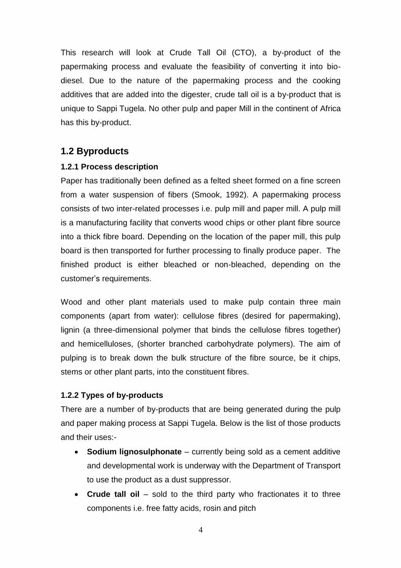
1.2.2 Types of by-products
There are a number of by-products that are being generated during the pulp
and paper making process at Sappi Tugela. Below is the list of those products
and their uses:-
Sodium lignosulphonate – currently being sold as a cement additive
and developmental work is underway with the Department of Transport
to use the product as a dust suppressor.
Crude tall oil – sold to the third party who fractionates it to three
components i.e. free fatty acids, rosin and pitch
5
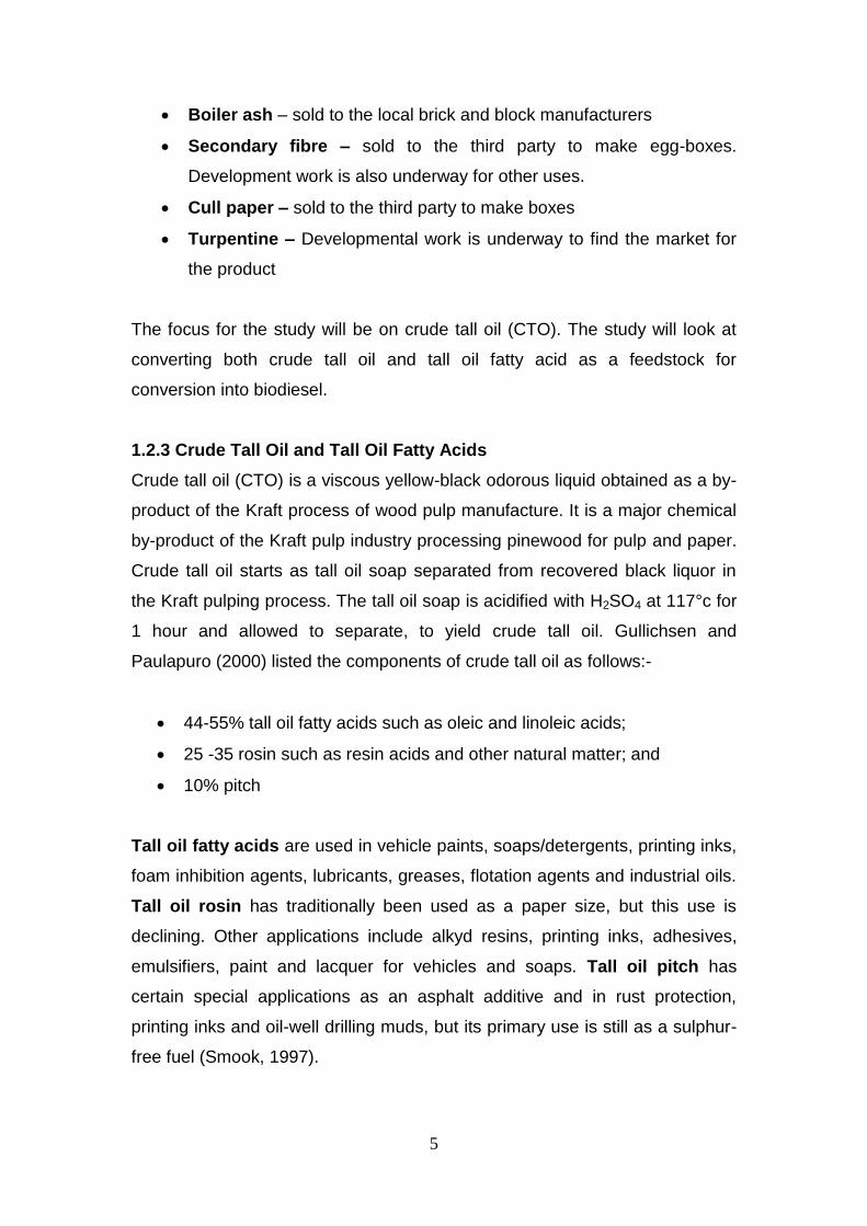
Boiler ash – sold to the local brick and block manufacturers
Secondary fibre – sold to the third party to make egg-boxes.
Development work is also underway for other uses.
Cull paper – sold to the third party to make boxes
Turpentine – Developmental work is underway to find the market for
the product
The focus for the study will be on crude tall oil (CTO). The study will look at
converting both crude tall oil and tall oil fatty acid as a feedstock for
conversion into biodiesel.
1.2.3 Crude Tall Oil and Tall Oil Fatty Acids
Crude tall oil (CTO) is a viscous yellow-black odorous liquid obtained as a by-
product of the Kraft process of wood pulp manufacture. It is a major chemical
by-product of the Kraft pulp industry processing pinewood for pulp and paper.
Crude tall oil starts as tall oil soap separated from recovered black liquor in
the Kraft pulping process. The tall oil soap is acidified with H2SO4 at 117°c for
1 hour and allowed to separate, to yield crude tall oil. Gullichsen and
Paulapuro (2000) listed the components of crude tall oil as follows:-
44-55% tall oil fatty acids such as oleic and linoleic acids;
25 -35 rosin such as resin acids and other natural matter; and
10% pitch
Tall oil fatty acids are used in vehicle paints, soaps/detergents, printing inks,
foam inhibition agents, lubricants, greases, flotation agents and industrial oils.
Tall oil rosin has traditionally been used as a paper size, but this use is
declining. Other applications include alkyd resins, printing inks, adhesives,
emulsifiers, paint and lacquer for vehicles and soaps. Tall oil pitch has
certain special applications as an asphalt additive and in rust protection,
printing inks and oil-well drilling muds, but its primary use is still as a sulphur-
free fuel (Smook, 1997).

6
1.2.4 Quantities of crude tall oil
The graph below indicates the quantities of crude tall oil production from the
financial period of 2007 to 2009.
Figure 1.2 – Monthly CTO production
It can be observed that the average production of crude tall oil is 400
tons/month. This tonnage represented significant revenue for the Mill – almost
R 12 mil/annum as the product is sold to the third party.
The preliminary research on the potential income that is likely to be generated
if the product is converted to biodiesel was R 35 mil/annum (Murray, 2007).
It, therefore, became paramount that the research be under-taken as it has a
potential to make a significant improvement in the financial performance of the
Mill as well as of the entire Sappi Group.
1.2.5 Biofuel
Humanity’s dependence on petroleum for transportation fuel comes at a high
cost. The environmental impact of fossil fuels is well documented and known.
They contribute to global warming by transferring previously sequestered
carbon molecules into the atmosphere as carbon dioxide which is a
greenhouse gas (Knothe, 2001). They are also a major source of air pollution
0
200
400
600
800
1000O
ct-
07
Feb
-08
Ju
n-0
8
Oct-
08
Feb
-09
Ju
n-0
9
Date
Mo
nth
ly C
TO
pro
du
cti
on
(to
ns)

7
through other combustion products found in the exhaust systems of vehicles
(Hirsch, 2005). In addition to environmental negatives, the nations that cannot
supply their own petroleum needs are forced into an unfavourable balance of
payments with petroleum exporters.
Biofuels offer a partial solution to many of these problems mentioned above. It
has been claimed that biofuels do not contribute to global warming (Brown,
2003). Like petroleum, exhaust fumes from biofuels contain carbon dioxide.
Since plants remove carbon dioxide from the atmosphere during
photosynthesis, the net production of CO2
is arguably zero (Mittelbach and
Remschmidt, 2005). The levels of other pollutants are also generally lower
with biofuels than with petroleum. The fuel stocks for biofuels are produced by
domestic agriculture, which means that biofuels production occurs
domestically as well.
Biodiesel is a diesel fuel substitute produced from renewable sources such as
vegetable oils, animal fats, and recycled cooking oils. Chemically, it is defined
as the mono alkyl esters derived from renewable sources (Friedrick, 2003).
Biodiesel is typically produced through the reaction of a vegetable oil or
animal fat with methanol or ethanol in the presence of a catalyst to yield
glycerine and biodiesel - chemically called methyl or ethyl esters (Biodiesel
Education, 2006). These oils are expensive and they generally account for 60
– 80% of the total cost of biodiesel production (Mittelbach and Remschmidt,
2005). The fluctuating price of crude oil provokes the need for the other
source of fuel globally.
1.3 Justification for the study
1.3.1 Previous studies
There are a number of studies that relate to biodiesel production that have
been conducted and published. Most of them have used spent cooking oil and
vegetable oil as feedstocks. These were conventionally converted with much
success because of the level of fatty acids present in the feedstock (Balat,
2005).

8
There is also a study conducted by Schulte in 2007, where he looked at
converting both the chicken fat and crude tall oil into biodiesel. The two
feedstocks were studied individually as well as a blend. He considered
conventional base and acid catalysed procedures and found them to be
inappropriate for his study, due to the high fatty acid content within the
feedstocks. He then found supercritical methanol treatment as a method of
choice.
The results from his study indicated that chicken fat and crude tall oil from
Canada can be converted to biodiesel successful. The yields that were
achieved for this study were 89 and 94% respectively. He also concluded that
the two feedstocks could not be converted as a blend due to the excessive
methanol that was required for the reaction.
The properties of the biodiesel produced from study were acceptable by the
ASTM D6751 standard which is a requirement that is set-up by a control body
for the diesel engines in Canada.
1.3.2 Crude tall oil composition
The graph below indicates the variations of the crude tall oil composition
across different regions.
Figure 1.3 – Variation of crude tall oil composition
Variation of Crude Tall Oil composition
0
10
20
30
40
50
60
70
80
90
So
uth
ern
Sta
tes
Mid
dle
Atl
an
tic
Sta
tes
Ca
na
da
Sc
an
da
na
via
Mid
dle
Ea
st
We
st
of
Ca
sc
ad
es
So
uth
ern
Afr
ica
Co
mp
osit
ion
of
CT
O
Fatty acids Resin Acids Unsaponifiables

9
It can be observed from the figure above that the composition of the Southern
African’s crude tall oil is significantly different to the other regions that are the
dominants suppliers of crude tall oil in the world. This could be attributed to
the weather and geographical condition in the different countries.
1.3.3 Purpose of this study
It was therefore important to evaluate the feasibility of converting Southern
African’s crude tall oil into biodiesel. This was critical to establish and
determine the effect of the higher free fatty acids and the lower unsaponifiable
that are prevalent from the crude tall oil in the Southern Africa if compared
with the product from the other countries. Also, the South African Engine
Manufacturers’ Association, which is an approving body for the biodiesel that
is used in engines, needed to ascertain whether the biodiesel produced from
the Southern African crude tall oil will meet the specification set out by the
Department of Energy and Minerals (specification attached as Appendix 1).
Also, to address the financial challenges that Tugela Mill finds itself in
currently, it is necessary to consider the possible revenue generating streams
and quantify their viability.

10
CHAPTER 2
OBJECTIVE AND APPROACH
2.1 Objective
The overall objective of this study was to evaluate the feasibility of converting
of crude tall oil and tall oil fatty acids into biodiesel.
The specific objectives of the study were to:-
Develop criteria for selecting the best procedure for converting crude
tall oil and tall oil fatty acids into biodiesel;
Select the most suitable procedure for investigation;
Evaluate the effects of important parameters on the final biodiesel yield
and quality;
Test the final biodiesel product produced from both the feedstock and
compare it to SANS 1935 Automotive diesel fuel standard; and
Perform an economic evaluation.
2.2 Approach and Thesis Organization
Chapter one gives an overview of the pulp and paper industry in South
African and the need for this study.
Chapter two provides the objective and approach of the study.
Chapter three is the literature survey on both crude tall oil and
biodiesel.
Chapter four discusses the selection of a conversion procedure that
was chosen for the investigation
Chapter five describes the apparatus and the protocol that was
followed during the study
Chapter six presents and discusses the results that were obtained
during the study

11
Chapter seven discusses the overall economic consideration
Chapter eight concludes the findings and presents some
recommendations.

12
CHAPTER 3
LITERATURE REVIEW
3.1 Introduction
The literature reviews will cover the three important aspect of the study. The
first aspect of the study is the basic pulp and paper process, with the
emphasis on the papermaking processes and the crude tall oil chemistry.
The second aspect of the study will look at generic conversion procedures for
the spent oil and the specific processes that were considered for the study.
The third aspect will be on biodiesel. In this section, the advantages and
disadvantages of using biodiesel will be discussed. The important parameters
that are stipulated by the Engine Manufacturers Association for the biodiesel
to be suitable for use in the cars will also be discussed.
3.2 Basic papermaking process
(Standard Operating Procedure and the Operator’s Manual from Sappi Tugela
were used during the basic papermaking process description, unless
otherwise stated).
Papermaking process can be divided into 5 interrelated phases i.e. forestry,
wood preparation, pulp preparation, paper formation and paper finish. Below
is a simplified flow diagram for the integrated pulp and paper mill.

13
Figure 3.1 – flow diagram for a basic pulp and paper making
3.2.1 Forestry
This process involves growing and harvesting trees according to the required
final product specification. Paper producing entities and companies have
separate forestry operations that are independently run by competent
personnel. After a specified growing period, normally 16 – 18 years, trees are
harvested and transported to the paper mills for further processing.
The types of trees used for papermaking can be divided into two major
categories i.e. hardwoods and softwoods which are the main sources of wood
fibres in South Africa. Hardwood (eucalyptus) generally lose their leaves in
autumn, softwoods (pine) are usually evergreen.
Step 1 - Forestry
Step 5 – Paper
Finishing
Step 4 – Paper
Formation
Step 3 – Pulp
Preparation
Step 2 – Debarking,
Chipping and Recycling

14
Softwood fibres are longer, larger in diameter and have a higher density while
hardwood fibres are shorter, smaller in diameter and a lower density. The
yield of pulp per unit volume of wood is usually directly related to density. A
high wood density generally indicates a slower beating response, lower
tensile, burst and fold strength, greater bulk and higher tear strength (Smook,
1992).
Generally, hardwood contains a larger proportion of holocellulose and less
lignin as compared to softwoods, but a greater percentage of extractives
(Harshaw, 2000).
3.2.2 Wood Preparation
Wood preparation consists of a series of operations which convert the wood
into a form suitable for the subsequent pulping operations. In most cases, the
ultimate product is wood chips.
Wood is unloaded from a truck or railcar by a front-end loader or by an
overhead travelling crane. This process involves transportation in slasher
deck, where the logs are sorted and cut into manageable lengths, followed by
debarking, chipping, chip screening, and conveyance to storage. Chips are
usually stored in outside piles.
3.2.2.1 Debarking
The loading deck is the first element of a log handling operation. The logs are
aligned and transported onto sorting and/or slashing and then to debarking
system. Log debarking is necessary to ensure that the pulp is free of bark and
dirt. Mechanical and hydraulic debarking are the most commonly used bark
removing methods. In the mechanical debarking, bark is removed from the
logs by friction created from the rotating drum action as the logs rub against
each other. In the hydraulic debarking, bark is removed by directing high
pressure jets of water against the log. Bark removal is efficient and wood
losses are usually under 2% with this method, but the effluent generated is
difficult to clean up and the pollution problems have caused many mills to
switch from hydraulic to mechanical barkers.

15
3.2.2.2 Chipping
After debarking, the logs are reduced to chip fragments suitable for the
subsequent pulping operations. Flywheel-type disc are the most common
chippers used in the industry. The ideal chip size is usually considered to be
about 20mm long, and about 4 mm thick, but all chips 10 to 30 mm long and 2
to 5 mm thick are prime materials for pulping. Off-size chips adversely affect
the processing and quality of pulp.
3.2.2.3 Chip Screening
Acceptable size chips are usually isolated from fines and oversized pieces by
passing the chips over multi-stage vibratory screens. The oversized chips are
rejected to a conveyor, which carries them to a “rechipper” usually
hammermill that crushes the chips into smaller fractions. The fines are usually
burned with the bark.
3.2.2.4 Chip storage
Chip storage is widely utilized primarily because chips are more economical to
handle than logs. Outside chip storage is the most common chip storage
method, because large inventories of chips can be stored. There are some
disadvantages with this method e.g. blowing of fines, air-bone contamination.
It is always advisable to provide a ground barrier of concrete or asphalt before
building a chip pile to reduce dirt contamination and inhibit any micro-
organisms attack on the chip pile. Chip should be stored on a first-in/first-out
basis to avoid infection of fresh chips by old chips.
Optimum chip handling depends partly on pulping requirements. Since loss of
extractives is high for the first two months of outside storage, all chips for
sulphite pulping should go to storage. If by-product recovery is important, then
fresh chips should bypass storage wherever possible to maximise yield.
3.2.3 Pulping/cooking Process
Pulping process is the means to rupturing the bonds within the wood structure
(Smook, 1992). The task can be accomplished mechanically, thermally,
chemically or by combination of these methods.

16
3.2.3.1 Mechanical Pulping
Mechanical pulping is a process whereby wood is subjected to roughened
stone grounding which revolves at a speeds of 1000 to 1200 m/min. Fibres
are torn out of the wood, abraded, and removed from the surface of the stone
with water. The fibres which have form a low consistency by now are
screened to get rid of slivers and other undersize and oversize material, and
the consistency of the slurry is increased by removing the water to prepare
the stock for papermaking process.
This pulping process have not had much success because of the energy
requirements, though the high yield of 95% of conversion from wood into
chips have been recorded in some pulp Mills. Also, the paper that is formed
from Mechanical pulp is weak, highly opaque which is an advantage to the
printers but it tends to discolour, if is exposed to light (Smook, 1992).
Mechanical pulps are most often produced from softwood sources. The
smaller, thinner hardwood fibres are more severely damaged during
mechanical pulping and yield a finer, more flour-like material that forms an
exceedingly weal sheet. Some hardwoods produce an exceptionally bright
pulp that is sometimes blended with softwood mechanical pulp to improve
optical properties (Janse and Ottisch, 2005).
3.2.3.2 Chemical Pulping
Chemical Pulping is also another pulping process that is widely used in the
industry. This process is successful in degrading, dissolving and removing the
lignin away from cellulose and hemicellulose by means of chemical reactions.
Table 3.1 gives a brief description of different chemical pulping processes and
the additives that are utilized in this process.
Lignin is the glue-type material that binds the hemicellulose and cellulose
material within the tree structure. Cellulose and hemicellulose is the material
that is required to produce paper. However, the yield on this process is
around 40 – 50%, and this can be attributed to the vigorous cooking that takes
place in the cooking equipment – digester.
17
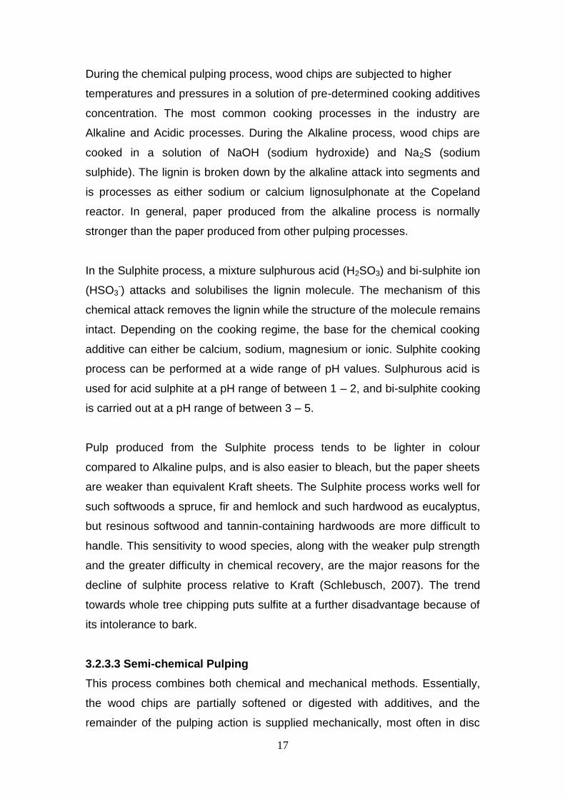
During the chemical pulping process, wood chips are subjected to higher
temperatures and pressures in a solution of pre-determined cooking additives
concentration. The most common cooking processes in the industry are
Alkaline and Acidic processes. During the Alkaline process, wood chips are
cooked in a solution of NaOH (sodium hydroxide) and Na2S (sodium
sulphide). The lignin is broken down by the alkaline attack into segments and
is processes as either sodium or calcium lignosulphonate at the Copeland
reactor. In general, paper produced from the alkaline process is normally
stronger than the paper produced from other pulping processes.
In the Sulphite process, a mixture sulphurous acid (H2SO3) and bi-sulphite ion
(HSO3-) attacks and solubilises the lignin molecule. The mechanism of this
chemical attack removes the lignin while the structure of the molecule remains
intact. Depending on the cooking regime, the base for the chemical cooking
additive can either be calcium, sodium, magnesium or ionic. Sulphite cooking
process can be performed at a wide range of pH values. Sulphurous acid is
used for acid sulphite at a pH range of between 1 – 2, and bi-sulphite cooking
is carried out at a pH range of between 3 – 5.
Pulp produced from the Sulphite process tends to be lighter in colour
compared to Alkaline pulps, and is also easier to bleach, but the paper sheets
are weaker than equivalent Kraft sheets. The Sulphite process works well for
such softwoods a spruce, fir and hemlock and such hardwood as eucalyptus,
but resinous softwood and tannin-containing hardwoods are more difficult to
handle. This sensitivity to wood species, along with the weaker pulp strength
and the greater difficulty in chemical recovery, are the major reasons for the
decline of sulphite process relative to Kraft (Schlebusch, 2007). The trend
towards whole tree chipping puts sulfite at a further disadvantage because of
its intolerance to bark.
3.2.3.3 Semi-chemical Pulping
This process combines both chemical and mechanical methods. Essentially,
the wood chips are partially softened or digested with additives, and the
remainder of the pulping action is supplied mechanically, most often in disc
18
refiners. Semi-chemical encompasses the entire intermediate range of pulp
yields between pure mechanical and pure chemical pulping i.e. 55 to 90% on
dry wood.
The neutral sulphite process (NSSC), is the most widely used semi-chemical
process. This process utilizes sodium sulfite cooking liquor which is buffered
with sodium carbonate to neutralize the organic acids liberated from the wood
during cooking. Spent liquors from semi-chemical pulping operations cannot
be discharged directly into receiving waters because of high chemical losses
and pollution loads. Processing of spent liquors can be readily accomplished
in cross- recovery with an existing Kraft or sulfite mill recovery system. Where
cross recovery is not possible, fluidized bed incineration is the most common
method used for disposal and recovery.
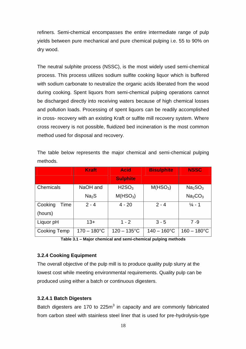
The table below represents the major chemical and semi-chemical pulping
methods.
Kraft Acid
Sulphite
Bisulphite NSSC
Chemicals NaOH and
Na2S
H2SO3
M(HSO3)
M(HSO3) Na2SO3
Na2CO3
Cooking Time
(hours)
2 - 4 4 - 20 2 - 4 ¼ - 1
Liquor pH 13+ 1 - 2 3 - 5 7 -9
Cooking Temp 170 – 180°C 120 – 135°C 140 – 160°C 160 – 180°C
Table 3.1 – Major chemical and semi-chemical pulping methods
3.2.4 Cooking Equipment
The overall objective of the pulp mill is to produce quality pulp slurry at the
lowest cost while meeting environmental requirements. Quality pulp can be
produced using either a batch or continuous digesters.
3.2.4.1 Batch Digesters
Batch digesters are 170 to 225m3 in capacity and are commonly fabricated
from carbon steel with stainless steel liner that is used for pre-hydrolysis-type

19
cooks. Screened chips are charged into the top of the digester. The volume of
white liquor and black liquor required for the target active alkali percentage
and liquor to wood ratio, respectively, is then metered simultaneously into the
digester.
When the digester is fully charged with chips and liquor, it is capped. The
batch digester is provided with a circulation system and heat exchanger for
bringing the contents to pulping temperature. Direct heating by injection of
steam with convection mixing provides goo results and forced circulation
avoids liquor dilution, thereby maintaining higher alkali concentration during
the cook and eliminating an additional load on evaporators.
A common circulation design draws liquor from a perforated ring near the mid-
point of the digester through a heat exchanger, and distributes the return flow
to both the bottom and top of the vessel. The circulating pump is usually sized
to turn over the liquid contents of the digester about once every 10 minutes.
The loaded digester is brought up to maximum temperature according to a
preset rate, usually controlled by a clock-driven cam.
3.2.4.2 Continuous Digester
In Continuous digester, the wood chips are fed from a surge bin through a
volumetric chip meter and a rotary low pressure feeder into the steaming
vessel. A slowly turning screw carries the chips though the horizontal
steaming vessel, where flash steam at 1.05 kg/m3 preheats the chips and
drives off air and non-condensable. The chips then fall into a chute connected
to the high-pressure feeder. The feeder consists of a single rotating element,
when a filled pocket has moved 90°C, the chips are sluiced away with cooking
liquor and carried up to the digester inlet.
Here, the slurry enters a cylindrical separator, perforations in the plate allow
liquor to flow to the surrounding collection ring and be returned to the feeder,
while the chips are pushed downward by a rotating helical screw. When the
chips enter the digester, they have absorbed sufficient alkali to enable the

20
chips to move downward by gravity through the liquor-filled space at the top of
the vessel, until they settle on the chip mass.
The chips then moves downward as a uniform column without channelling
(i.e. plug flow) through the digester zones where chips are impregnated with
liquor through external heat exchangers. The retention time within the final
zone is 45 minutes at 105 – 130°C.
The pulp is continuously slushed from the column of cooled, softened chips by
slowly rotating paddles that are mounted on radical arms attached to the hub
of the outlet device. The pulp is then blown at a precise rate of 200 psig to an
atmospheric tank.
3.2.5 Processing of pulp
Pulps are subjected to a wide range of processing steps, depending on their
method of preparation.
3.2.5.1 Deknotting
Knots are defined as the fraction of pulp that is retained as wood chips on a
3/8 perforated plate. These rejects may be true knots or uncooked chips. The
knots are usually removed prior to pulp washing, either discarded as waste or
returned to the digester in-feed. Pressure screen knotters are most commonly
used. They consist of a totally enclosed cylindrical, perforated screen through
which accepted stock flows. A rotating foil produces a series of pressure and
vacuum pulses to keep the perforation clean. Knots are retained on the
entrance side of the screen and are continuously discharged, along with some
good fibre. The main drawback of the pressure knotter is the consequent
need for a secondary screen to return good fibre back to the system.
3.2.5.2 Pulp washers
The cooked pulp from the digesters must be washed with the objective to:
Remove residual liquor that would contaminate the pulp during
subsequent processing steps; and

21
Recover the maximum amount of spent cooking chemicals with
minimum dilution.
There are a number of pulp washers that the industry uses i.e. rotary vacuum
washers, diffusion washer, rotary pressure washer, horizontal belt filter, wash
press and dilution/extraction. These methods are dependent on the fibre
characteristics, shower characteristics, sheet formation and thickness and
operating factors.
Rotary vacuum washers are the most used pulp washers and they consist of
wire or clothed covered cylinder that rotates in a vat containing the pulp slurry.
By means of internal valving and a sealed barometric down-comer, vacuum is
applied as the rotating drum enters the stock. A thick layer of pulp builds up
and adheres to the wire face as it emerges from the vat. Wash water is
applied to displace the black liquor in the sheet as the drum continues to
rotate. Finally, the vacuum is cut off and the washed pulp is removed from the
mold. About 3 or 4 stages of washers are required to attain an overall
satisfactory removal of about 99% of the washable liquor solids.
3.2.5.3 Screening
Screening is required to remove oversized, troublesome and unwanted
particles from good papermaking fibres. Screens depend on the perforated
barrier to pass acceptable fibre and reject the unwanted material. In most
instances, it is the size of the perforations that determine the minimum size of
debris that will be removed.
3.2.5.4 Centrifugal cleaning
Centrifugal cleaning removes unwanted particles (such as sand and dirt
solids) from pulp by a combination of centrifugal force and fluid shear.
Therefore, it separates not only on the basis of weight difference, but also
particle shape to some extent. Centrifugal cleaners work on the principle of a
free vortex generated by a pressure drop to develop centrifugal action. The
stock enters the cleaner tangentially, the inlet scroll guides the flow to impact
a rotating motion.

22
3.2.5.5 Thickening
Following low-consistency operations such as cleaning and screening, it is
necessary to thicken the stock (with or without washing) prior to the next
process operation. A variety of equipment is used for this operation and it
depends mostly on the consistency of the final pulp that is required. Gravity
thickeners are the most commonly used equipment. Water flows into the
cylinder by virtue of the difference in liquid level between the vat and cylinder.
Pulp is retained on the rotating cylinder and is couched off by a rubber roll.
3.2.5.6 Pulp storage
After thickening of the pulp into consistency of around 16%, it is stored for
further use in the process. Pulp storage takes place at various points in the
process to provide surge capacity and allow for interruptions in either supply
or demand.
The final pulp storage takes place after pulp thickening. At this stage of the
process, the pulp is ready to be sent to the paper machine for papermaking.
3.2.6 Recovery of Pulping liquors
The recovery of spent cooking liquors, the reconstitution of these liquors to
form fresh cooking liquor, the realization of energy from incineration of organic
residuals, and minimisation of air and water pollution, are all vital parts of the
pulping process. These objectives are achieved through a well-defined series
of steps, starting with the weak black liquor from the brown stock washers:-
Concentration of liquor in multiple-effect evaporators to form strong
black liquor;
Black liquor oxidation;
Further concentration of liquor to form heavy black liquor;
Addition of salt cake to make up soda loss;
Incineration of liquor in recovery furnace;
Dissolving smelt from the furnace to form green liquor;
Causticizing of green liquor with lime to form white liquor; and

23
Burning of lime mud to recover lime.
By-product recovery
Two by-product of alkaline pulping are economically important i.e. turpentine
and tall oil. Both products are obtained in quantity when pulping resinous
woods such as pine.
3.2.6.1 Turpentine
Turpentine is recovered primarily from the digester relief gases. The gases
are conducted to a cyclone separator where liquor carryover is removed, then
to a condenser while giving up their heat to process water. The condensate
drains to a decanter where the turpentine and water separate and overflow
from top and bottom, respectively. The water is combined with other
contaminated condensate streams for steam stripping, while the turpentine
flows to a storage tank. While the turpentine sits in storage, additional water
separates and settles to the bottom of the tank.
Chemically, turpentine consists of a number of cyclic compounds, principally
pinenes and turpenes. The raw turpentine is sold to chemical processors
where it is fractionally distilled and converted into numerous products,
including camphor, synthetic resins, solvents, flotation agents and
insecticides.
3.2.6.2 Tall Oil
The resinous material in pines and other species is made up fatty acids and
resin acids, as well as sterols and related alcohols. During Kraft cooking, the
fatty and resin acids become saponified (i.e. are made into sodium soaps).
During black liquor cooling and evaporation, the soaps and other precursors
of tall oil become insoluble and rise to the surface of the liquor. The black
liquor is usually concentrated to about 24% to 28% solids, then taken from
one effect of the evaporators to a skimming tank where the soap is removed.
The skimmed liquor is then returned to the next evaporator effect. The

24
recovered soap is allowed to settle in storage to remove additional entrained
liquor.
Some mills sell the recovered soaps to oil processing plants without further
refinement. However, a large number of mills, especially where waste
sulphuric acid is available from other operations, carry out an acidulation
process to convert the soap into raw tall oil and recover the soda. The
following reaction is typical:
Na·R + H2SO4 ------> H·R + Na2SO4
The acidulation mixture is either allowed to separate in a settling tank or is
processed through a continuous centrifugal separator. The acid phase
containing sodium sulphate and residual lignin is added to the black liquor
system. The tall oil is washed with hot water to remove free acid and is
allowed to settle in storage tanks prior to shipment.
3.2.7 Papermaking
Non-fibrous additive
A wide range of additives are added into a pulp stock to impart or enhance
specific sheet properties or to serve other necessary purposes. These
additives are classified as wet-end and dry-end chemistries. Wet-end
additives are those additives that are added in pulp stock while the stock has
a consistency of less than 3%. Below is the table depicting some of these
additives and their application:-

25
Table 3.2 – Paper additives and their applications
Additive Application
Sizing agents Control penetration of liquids in the
paper sheet
Wet strength resins Add wet strength to such grades as
towelling and wrapping
Fillers (e.g. clay, talc, TiO2, etc.) Improve optical and printing
properties
Colouring materials (dyes and
pigments)
Imparts desired colour
Retention aids Improve retention of fines and fillers
Fibre deflocculants Improve sheet formation
Defoamers Improve drainage and sheet
formation
Optical brightness Improve apparent brightness
Pitch control Prevent deposition and accumulation
of pitch
Dry-end chemistries are added into the sheet of paper when the paper is dry
to enhance the properties.
The basic component of the paper machine is stock inlet, head box, four-
drinier wire, press section, dry section, calendar section and reel.
The stock inlet comprises of the screens and cleaners which acts as
insurance against foreign contamination, although the pulp furnished to the
paper machine should be reasonably free from impurities (assuming good
screening and cleaning control in the pulp mill). These screens function
mainly to remove gross contamination and to de-floc the fibres, while the
centri-cleaners are designed to remove debris. The heart of the stock inlet is
the fan pump which serves to mix the pulp stock and the water and deliver the
blend to the head box. To ensure a uniform dispersion to the head box, the
stock is fed from a constant head tank (called stiff box), through a control
26
valve called basis weight valve, and is usually introduced axially into the
suction line of the fan pump.
The function of the head box is to take the stock delivered by the fan pump
and transform the pipeline flow into a uniform, rectangular flow equal in width
to the paper machine and at uniform velocity in the machine direction. The
following may also be listed as primary objective of the head box system:-
Spread pulp stock evenly across the width of the machine;
Level out cross-current and consistency variations;
Level out machine direction velocity gradients;
Create controlled turbulence to eliminate fibre flocking; and
Discharge an even flow from the slice opening and impinge on the wire
at the correct location and angle.
The fourdrinier wire is an endless, finely woven belt where the paper
formation takes place. The sheet forming process involves water drainage,
such effects as the generation and decay of turbulence, formation and
breakdown of fibre networks, retention and transport of fine particles in the
mat, compaction of the mat, and shear forces between the mat and free
suspension. The most important effect of the drainage process is the
dewatering of the fibre suspension to form the mat. When fibres are free to
move independently of one another, drainage proceeds by the mechanism of
filtration and the fibres are deposited in discrete layer. Filtration is the
dominant mechanism in most fourdrinier forming applications. When the fibres
in suspension are immobilized, they floc together in coherent networks,
drainage then occurs by thickening and a more felted and floccy sheet
structure results.
Papermaking suspensions spontaneously form networks during drainage,
unless either sufficient dilution is used or supplemental mixing energy. Dilution
is a powerful mechanism for dispersion, but the level required to adequately
control flocking on paper machines is not economically feasible. Additional

27
dispersion must be generated during drainage by the turbulence-inducing
effects of drainage elements below the forming wire or by shear-inducing
devices above the wire.
Once the paper sheet has been formed at the fourdrinier wire, it is then
transferred into a press section. The primary objectives of pressing section
are to remove excess water and to consolidate the sheet web. The press
section also provides surface smoothness, reduce bulk and promote higher
wet web strength for good runnability in the dryer section. The paper web is
conveyed from the forming unit on a series of felts through the various
presses and into the dryer section. The pressing section is considered an
extension of the water-removal process that was started on the wire. It is by
far more economical to remove water by mechanical means than by
evaporation, so the papermaker is always looking for methods to improve
pressing efficiency, reduce evaporation as well as reduce the evaporate load
into the dryer section.
Sheet consolidation is a crucial phase of the papermaking process. It is here
that the fibres are forced into intimate contact so that good fibre-to-fibre
bonding develops during drying.
The objective of the dryer section is to evaporate the residual moisture in the
pressed sheet at an efficient rate and at low steam usage. The wet paper from
the press section containing about 60% moisture (40% dryness) is passed
over a series of steam-heated rolls (usually of 60 or 72 inches diameter),
where the moisture is evaporated and carried away by ventilation air. The wet
web is held tightly against the rolls by a synthetic, permeable fabric called
dryer felt. The dryer section is by far the most expensive part of the paper
machine with respect to both capital costs and operating cost.
Machine calendering is the passage of paper through one or more nips
formed by a set of iron rolls, and is the principal operation that is always
carried out on machine. The sheet from a dryer section is passed through a
machine calendering to reduce sheet thickness to the desired level, even out

28
calliper variations so that a good reel can be built and impact desirable
surface properties, primarily smoothness.
After drying and calendering, the paper must be collected in a convenient
form for further processing in a reeling section. The reel drum called a pope
reel is motor-driven under sufficient load to ensure adequate tension on the
sheet from the calendars. During the normal operation, the web wraps around
the drum and feeds into the nip formed between the drum and the reel held by
the secondary arms. Paper builds up on the reel while an empty spool is
positioned on the primary arms. Before the reel has built up to the required
diameter; the new spool is accelerated up to machine speed by a rubber
wheel and then loaded by the primary arms against the reel drum. When the
reel’s built-up is complete, the secondary arms release their pressure against
the drum, causing the paper reel to slow down, a loop of paper then billows
out between reel and drum, which is blown upward by air jets. At the proper
moment, the back tender breaks the sheet at the loop so that it wraps the new
spool. The full paper reel is then removed from the reel rails by a crane.
Once paper is established on the new spool, the primary arms are lowered so
that the spool rests on the reel rails. The secondary arms then engage the
reel spool to maintain the driving pressure of the reel on the drum. The
primary are disengaged and returned to the upright position to receive a new
spool.

29
3.3 Crude Tall Oil
3.3.1 What is Crude Tall Oil?
Crude Tall Oil (CTO) is a viscous yellow-black odorous liquid obtained as a
byproduct of the Kraft process of wood pulp manufacture (Smook, 1997).
Crude tall oil production process is depicted by a simplified diagram in Figure
3.2a and a detailed diagram in Figure 3.2b respectively. Crude tall oil is a
major chemical by-product of the Kraft pulp industry. Its name comes from the
Swedish word for pine, "tall", and indicates that the primary source is pine.
3.3.1.1 Origin of Crude Tall Oil
The resinous material in pines and other species is made up fatty acids and
resin acids, as well as sterols and related alcohols. After the pulping process,
the pulp is blown into the blow tank and the liquor is pumped to the
evaporators to increase its solids to about 25%. This liquor contains tall oil
soaps (sodium salts) and residual cooking additives i.e. sodium hydroxide and
sodium sulphate. As the liquor leaves the digester to the evaporator, the
concentration is about 15%, and the sodium salts (tall oil soaps) concentration
is about 1.35 g/100g total solids. As will be discussed in the subsequent
Chapters, the solubility of tall oil soaps depends on the total solids. At 25%
and above, concentration of tall oil soaps, solubility drops. This can be
attributed to the effect of ion that is caused by sodium (Na+) ions. At 25% and
above, the high concentration of lignates causes tall oil soap to be soluble,
and the rate of separation of soap on liquor that is skimmed off is slowed
down by the apparent increase in viscosity. McSweeney (1987) cited this
reduction in separation as the reason that the tall oil soap needs to be
skimmed off when the liquor is at 25% solids and above.
The solids on the liquor are increased to 25% through evaporation, and the
liquor is pumped into a skimming tank. These skimming tanks are normally
arranged and operated in series. The liquor is pumped to the first skimming
tank, where soap overflow on top and transferred to the second skimming
tank. The underflow is concentrated further at evaporators to a concentration
of 45%.

30

31

32
At the second skimming tank, the underflow is recycled at the recovery
boilers. There is about 0.58g/100g of tall oil in this underflow which goes to
the recovery boilers. A temperature of between 60°C to 100°C needs to be
maintained as any drop in temperature will results in pumping problems for tall
oil soaps (Gullichsen and Lindeberg, 1999)
Spent sulphuric acid is used to wash the crude tall oil soap before it enters the
first storage tank. The soap is then pumped into the second storage tank until
there is sufficient tall oil soap for the reaction. Depending on the size of the
pulp Mill and the volume of the soap from the pulping process, a reaction is
carried out once a day.
A pre-determined amount of soap is pumped into a reaction vessel that is
usually made up of monel or nickel steel. Steam is injected into a reactor to
heat up the mixture to a boiling point, and thereafter the acid is added. The
optimum temperature for the reaction is achieved by the heat of dilution of the
sulphuric acid. It is imperative at this stage to ensure that there is uniformity in
the reaction, steam is therefore added at a pre-determined rate and constantly
agitated by the use of mixers and stirrers. The reaction takes place for 2 hours
and the pH is closely monitored. Once the pH reaches 4.0, the reaction is left
to settle overnight. The corrosiveness nature of the sulphuric acid means that
all metal pipes in the machinery used for the process must be constructed of
stainless steel.
Below are the reactions that take place:-
Crude Tall oil
R—COO-Na+ + H+ → R—COOH + Na+
This above reaction represents the ionic soap that is first converted into a
carboxylic acid and then into an oil. This reaction is observed for both fatty
acids and resin acids.
Lignins
Lignite - Na+ + H+ → Na+ + lignin2

33
The above reaction explains the presence of sodium lignates that are
precipitated by the acidulation reaction. An emulsion is formed between the oil
phase and aqueous phase when settling takes place.
Calcium ions
The sulphate ions that are given off by the acid combine with calcium ions in
the soap and they form a precipitate. Due to the weight/density of the
precipitate, it settles at the bottom of the tank and follows the following
reaction.
Ca++ + SO4 ------- CaSO4(s)
Sulphide ions
Below are the important reactions that take place during acidification of the tall
oil. There are substantial sulphide ions that are present during the tall oil soap
reaction. When sulphuric acid added, protonation that results in the formation
of H2S takes place, and this is demonstrated in the following:-
S2- + H+ ------- HS-
HS- + H+---------> H2S
Care must always be exercised during the reaction at the tall oil plant as H2S
fumes are always likely to surface. There are always unwanted particles
(CTO, emulsion for the lignin and aqueous), and these are pumped out of the
mixture. Depending on the requirement, the mixture is left overnight so that it
can settle.
Below is the procedure that is followed to treat the phases:-
Hot storage is to store CTO prior to pumping it to other parts of the
plants for further processing; and
In order to extract the tall oil products from the crude tall oil, it is
recycled and then pumped to the buffer tank. Hot water is pumped to
the reaction kettle. Tall oil is then pumped into a centrifuge feed tank.

34
Calcium sulphate and lignin solids are removed and dumped at this stage of
the process. This oil is not sufficiently pure and therefore cannot be pumped
into the CTO storage tank. It is pumped back into the reactors and mixed with
other soap batches.
Another phase of this process is aqueous phase. It is used in the initial part of
the process which is to wash off acid before soap goes into the first storage
tank. This phase is eventually sent to recovery boilers as a fuel source.
3.3.1.2 Yield during pulping
The normal yield is about 15-20 kg of tall oil per tonne of air-dried pulp, but for
slow growing species of trees, up to 100 kg can be obtained. The average
yield of CTO is in the range of 30-50 kg/t of pulp, which corresponds to 50-
70% of the initial amount in the raw material used for pulping (Smook, 1992).
This CTO is a saleable product for a pulping mill, but represents only about 1-
1.5% of the mill’s total revenue (Gullichsen and Lindeberg, 1999).
With the closing of the circulations in Kraft pulp mills, the role of the CTO plant
has become more important, as it is a major source of sulphur for addition to
the process and a part of the mill’s waste handling and removal system. The
availability of tall oil for a mill is greatly dependent on the wood species used
for pulping, the growth conditions of the trees and the method and duration of
storage of the logs and chips. Even among extractives-rich pine species,
however, there is significant variation in the availability of tall oil (Gullichsen
and Lindeberg, 1999; McSweeney, 1987).
3.3.1.3 Refining CTO
About 2 million tons of CTO are refined globally per year (Lindeberg and
Ulmgren, 1996; Gullichsen and Lindeberg, 1999). There is little use for it in its
raw state today, but it is purified and fractioned by vacuum distillation to yield
following base products:
tall oil fatty acids (TOFA);
tall oil rosin (TOR);

35
distilled tall oil (DTO);
tall oil heads; and
tall oil pitch.
Figure 3.4 - Simplified diagram of the tall oil distillation process (modified from Anon.
2006, McSweeney et al. 1987, McSweeney 1989)
3.3.1.4 Uses of CTO
Tall oil products have a wide range of applications, and the various base
products can be further refined into a wide variety of products and
formulations. Tall oil fatty acids are used as raw materials for the
manufacture paint vehicles, soaps/detergents, printing inks, foam inhibition
agents, lubricants, greases, flotation agents and industrial oils. Tall oil rosin
has traditionally been used as a paper size, but this use is declining. Other
applications include alkyd resins, printing inks, adhesives, emulsifiers, paint
and lacquer vehicles and soaps. Tall oil pitch has some special applications
as an asphalt additive and in rust protection, printing inks and oil-well drilling
muds, but its primary use is still as a sulphur-free fuel. (Grace, 2001;
Gullichsen and Lindeberg, 1999).

36
CTO can also be used as a lime kiln fuel, which is an attractive alternative
when it is of poor quality. It can replace the primary fuel oil partially or totally
and has almost the same heat value and combustion properties (Gullichsen
and Lindeberg, 1999). Emission trading has further increased the
attractiveness of this alternative nowadays.
3.3.1.5 Chemical composition and characterization of crude tall oil
The dark-coloured crude tall oil (CTO) is not composed of pure triglycerides
like other vegetable oils, but is rather a mixture of fatty acids, rosin acids and
unsaponifiable substances, e.g. sterols, waxes and hydrocarbons. The
precursors of CTO are the extractives found especially in coniferous trees.
Pine typically contains extractives such as free resin acids, fatty acids in the
form of glycerides, and turpenes. The extractives also contain neutrals or
unsaponifiable that are primarily alcohols of various kinds.
Several carboxylic acids, fatty acids and rosin acids are found in crude tall oil.
The predominant fatty acids, contributing the bulk of the observed physical
and chemical properties, are oleic and linoleic acids (Duncan, 2003), whereas
the main resin acids are abietic-type acids and primaric-type acids (Haas,
2005).
Figure 3.5 - The structure of resin (abietic) and fatty (oleic) acids prominent in crude
tall oil
37
The figure above represents the structure of resin and free fatty acids in the
Crude Tall Oil. It can be observed that abietic acids molecules are multi-ring
and bulkier compared to oleic molecules which are straight chained
molecules.
CTO varies considerably in composition and quality depending on the location
of the mill, time of year, growing cycle of the tree, tree species, ageing of the
wood, amount of heartwood, pulping conditions, handling and storage of the
wood and the efficiency of the system used to recover the tall oil (Anon, 2006:
Gullichsen and Lindeberg 1999). Furthermore, storage of CTO leads to
esterification of the sterols and other alcohols with fatty acids (Holbrom, 1978,
Avela and Holbrom, 1971a; Avela and Holbrom, 1971b), which will reduces
the number of acids it contains and increase its hydrophobicity.
3.3.1.6 Analyses of CTO
A commonly used measure of tall oil quality is the acid number (AN), which
indicates the number of carboxylic acid groups (total fatty and resin acid
content). Mills that use only pine have the highest quality CTO, with AN
values of 160-165 mg KOH/g oil, whereas mills that use 50% or more
hardwood in their furnish have a CTO with an Acid Number of 125-135
(Kusdiana and Saka, 2001).

38
Figure 3.6 – Typical composition of crude tall oil, w/w (Southern US)
Source: Schulte, W.S. 2007:11
Biodiesel production could be a very important use for the fatty acids found in
CTO. The fuel properties of biodiesel containing resin esters would require
further investigation, particularly when blended with petro-diesel or with
biodiesel fuels derived from different feedstocks.
3.4 Biodiesel
3.4.1 Introduction
Biodiesel is defined as the alternative fuel that is produced from vegetable,
animal and spent oils (Kusdiana and Saka, 2004). Biodiesel can be used as a
substitute for the diesel fuel or can be used a blend. With the exception of the
Cetane number that is higher, other characteristics and parameters are similar
with the diesel fuel for the biodiesel which enables its use to diesel engines
without any significant modification to the engine. There are also other

39
downstream benefits of using the biodiesel which are related to the
greenhouse effect and will be explained later in this report
Since biodiesel is biodegradable, and it does not contain sulphur and other
aromatic components, it offers the benefit of potentially reducing the
particulate and other emissions that are toxic. Jerry (2007) reported that
adding small amounts of biodiesel to conventional diesel can improve fuel
lubricity, extend engine life, and increase fuel efficiency.
3.4.2 Background
Rudolph Diesel inverted the diesel engine in 1900 (Nitske, 1965). He
converted vegetable oils into biodiesel for the first time. There were further
research studies that followed which were focused on alternate raw materials
and improving the quality of the biodiesel. Though most of the research was
carried out of interest, the shortage of fossil fuels prompted the countries
around the world to consider seriously the need for alternate fossil fuels
(Knothe, 2001).
The political intervention and the declaration of peace after the 2nd world war,
eliminated the shortage of fossil fuels and the need for the research on
biodiesel was reduced (Johnson, 2006).
Petersen and Gregory (2005) cited the following reasons to the increase in
interest in biodiesel production:
formation of OPEC around 1970’s;
increase in prices for fuel; and
possibility of fuel shortage.
There were also incentives that were introduced around 1991 that prompted
the need for biodiesel.

40
3.4.3 Biodiesel Use
There are a number of biodiesel uses that have been studied in the literature,
and have been successful tested and implemented in the engines. They
utilise biodiesel as a blend with other diesel product or in its pure state
depending on the required engine performance.
Pure state
This is the ideal state or form to use biodiesel as most of the documented
advantages of biodiesel are realised e.g. reduction in carbon monoxide
excretion, unburned hydrocarbons, etc. However, Biodiesel education (2006)
listed the following disadvantages that are associated with using biodiesel:
possibility of deposits in fuel tanks resulting from unburned
hydrocarbons;
degrading of fuel lines because of incompatibility of biodiesel and the
material of construction; and
paint damage along fuel fill ports.
Blend state
Friedrick (2003) said biodiesel is also used as a blend with fossil diesel to
eliminate the highlighted problems in the paragraph above, while benefiting
from advantages of biodiesel. This blend can blend up to 50% (biodiesel/fossil
diesel) and is normally expressed in terms of the biodiesel content in the
blend e.g. B50 (indicating that there is 50% biodiesel in the blend).
Additive
Friedrick (2003) said biodiesel can also be used as an additive during
lubrication. There has not been much research work conducted on this
aspect, but the cost-effectiveness that is provided by biodiesel as a lubricant
enhancer makes it an interesting research area that requires further exploring.
41
3.4.4 Advantages of biodiesel use
Using biodiesel has the following advantages for consumers (Journey to
Forever, 1999):
There is no specific need for modifying the diesel engine, if switching
to biodiesel;
Biodiesel burns 75% cleaner than diesel is considered
environmentally friendly;
Biodiesel is unlikely to contribute to the depletion of the ozone layer
because there is no net carbon dioxide that is emitted in the exhaust
fumes;
Biodiesel is biodegradable and is also not toxic; and
Biodiesel offers the extension of a life of an engine due to its lubricant
characteristics and the cetane number that is higher that diesel.
3.4.5 Disadvantages of biodiesel use
Beer and Grant (2005) listed the following as the disadvantages of using
biodiesel:-
Biodiesel produces high levels of NO2 because of the high oxygen
content. This happens mostly during combustion, and can be
neutralised by the use of a catalytic convertor and adjusting the timing
of the engine;
Care needs to be exercised during storage of biodiesel because it has
a low oxidation stability level. Also, because biodiesel is hygroscopic in
its nature, and contact with humid air should be prevented;
In certain cars, because biodiesel has a lower volumetric density
compared to fossil fuel, it is possible that for a similar distance covered
the usage might be higher;
Biodiesel has a higher cold-filter plugging point temperature than fossil
diesel which means it will crystallize into a gel at low temperature when
used in its pure form;
It can cause dilution of engine lubricant oil, requiring more frequent oil
changes than in standard diesel-fuelled engines;

42
Biodiesel is a strong solvent and scrubs out all the tars, varnishes, and
gums left by fossil diesel in the fuel system which means that the fuel
filter will have to be replaced a few times during the initial stages of
biodiesel use; and
A modified refuelling infrastructure is needed to handle biodiesel, which
adds to their total cost.
3.5 Generic oil conversion procedures into biodiesel
There are a number of generic conversion procedures that have been
traditionally used to convert oil into biodiesel. These procedures have utilised
vegetable oils because they offer good ignition characteristics and have been
used as fuels in diesel engines in times of fuel shortages (Friedrick, 2003).
However, some of the properties of vegetable oils, especially their viscosity
and quick oxidation tendency, make them undesirable for use in modern
diesel engines.
The viscosity of vegetable oils, when used as fuel, can be reduced in at least
four different ways:
Dilution;
Pyrolysis;
micro emulsion; and
Trans-esterification.
Of the above options, transesterification is the current method of choice, by
which vegetable oils can be converted into the products known as "Biodiesel",
with properties very similar to diesel fuel. Biodiesel can be used in its neat
form or as a blend in conventional diesel fuel. Various types of animal fats,
used oils and fats, and micro-algal oils can also be converted to biodiesel type
products. Two technologies exist for the conversion of vegetable or biomass
derived oils and animal fats to biodiesel.
3.5.1 Biodiesel by Esterification Process
The conversion procedure that has been used over the years to convert
vegetable oils and other forms of oils/fats into biodiesel in the presence of an

43
catalyst is called Esterification Process (Biodiesel Education, 2006). This
process involves combining oil (main raw material) with an alcohol base
(either ethanol or methanol) depending on their availability and costs as well
as the final product required. The process also used a carefully selected
catalyst (Na + KoH) to form methyl ester. The above process offered the
following advantages:
reduction of 1/3 of the molecular weight to that of the oil;
reduction of the viscosity by 1/8; and
an increase in the volatility.
The following are also process variables that need to be taken into
cognisance during transesterification as they affect the reaction time and the
efficiency of the process i.e.
Process temperature;
Type and the concentration of the catalyst used;
Feedstock to alcohol ratio; and
Mixing time.
Also, the extent to which the reactants are pure (e.g. any presence of
contaminants since the raw materials are by-products) is also crucial for the
successful conversion.
A stoichiometric material balance yields the following simplified equation:
Oil or Fat (1000kg) + Methanol (107.5 kg) = Methyl ester (1004.5 kg) + Glycerol (103 kg)
After the reaction, the products are separated into two phases which
facilitates easy removal of glycerol, a valuable industrial by-product, in the first
phase. The remaining alcohol/ester mixture is then separated and the excess
alcohol is recycled. The esters are sent to the clean up or purification process,
which consists of water washing, distillation, vacuum drying, and filtration. The
biodiesel produced from this process is commonly referred to as "vegetable
ester".

44
3.5.2 Biodiesel by Hydrogenation Process
The second process, which involves simultaneous catalytic hydrogenation
and cracking of vegetable and tree oils, was developed at the Saskatchewan
Research Council under the sponsorship of the (CANMET) Canada Centre for
Mineral and Energy Technology (Johnson, 2006). This process has been
used to produce biodiesel type material from "Tall Oil", a by-product from the
Kraft pulping process. The principal constituents of tall oil are the unsaturated
C18 fatty acids, resin acids and unsaponifiable hydrocarbons such as di-
terpenic alcohols/aldehydes. The biodiesel produced from this process has
been given the name "SuperCetane", due to its high cetane number which is
close to 60 (Canacki and Gerpen, 2001).
CANMET technology has been licensed to Arbokem of Vancouver, Canada,
to market the process worldwide. The world production of tall oil is estimated
to be a potential 1.2 million tonnes/year. Well over 60% of that comes from
the U.S. BC Chemicals is a leading producer of tall oil in Canada (Canada
Times, 2007).
In its traditional use, the crude tall oil (CTO) is first de-pitched and then
upgraded by distillation to produce more valuable products such as tall oil
fatty acids (TOFA) and tall oil rosin (TOR). The CANMET process which is
known to convert tall oil into higher value products, involves simultaneous
catalytic hydrogenation and cracking of the de-pitched tall oil (DPTO). Two
continuous trickle bed reactor systems were used in this programme. The first
unit, a once through semi-pilot plant with a 750 ml reactor was used for the
initial work. The second system uses a process development unit (PDU) with
a 10 litre reactor which fully simulates the features of the process in
commercial units, and was used to produce sufficient quantities of
SuperCetane for engine testing.
In the production process of SuperCetane, the DPTO feed is pumped into the
high pressure system where it combines with hydrogen. This gas-liquid phase
passes through a series of electric pre-heaters before entering the catalytic
trickle bed reactor. The product is collected in two flash columns, decanted to
remove the water and then distilled in a batch unit to obtain the desired cut.

45
The process gas is recycled after removing the impurities in a series of
scrubbers. Long duration pilot-plant runs were successfully carried out at
CANMET's Energy Research Laboratories in Ottawa, to convert tall oil into
SuperCetane, and the process is now ready for scale-up to industrial levels.
The production costs for SuperCetane including the capital and operating
costs in a large scale plant is estimated at 10 to 12 cents per litre (Mittelbach
and Remschmidt, 2005). The cost of the tall oil as raw material could vary
from 8 to 20 cents per litre of SuperCetane. The total cost of this biodiesel
product could range between 18 to 32 cents per litre, which makes it
economically more attractive than vegetable esters currently costing about 66
cents per litre.
3.5.2.1 Attempts to reduce cost of biodiesel
Between 75 and 90 per cent of the cost of biodiesel is the raw material
(Pramanik and Tripathi, 2005). In order to reduce the cost of biodiesel, it is
imperative to find oils sources that have less competition, and where biodiesel
could reign as the primary consumer. One possibility is waste frying oils. In
selecting a feedstock, the cost of raw materials, as well as the processing cost
and its effect on the quality of biodiesel and other by-products, need careful
assessment.
3.6 Crude tall oil and tall oil fatty acids conversion procedures
A number of procedures have been researched by different authors to convert
oils with high free fatty acids content into biodiesel. Below are the common
procedures that this report will discuss:
Base-catalysed transestefication;
Acid-catalysed esterification;
Acid/base reactions;
Enzyme catalysed reaction;
Hydroprocessing; and
Supercritical methanol treatment.

46
All of the above methods have been reported to show successes in the
production of diesel-equivalent biofuels. There are however predefined
conditions (e.g. purity and quality of the feedstock) for these procedures to be
effective in conversion feedstocks into biodiesel.
3.6.1 Base-Catalysed Transesterification
The success stories and research studies for biodiesel has mostly been those
that used vegetable oil as a raw material. Vegetable oils contain less free fatty
acids (below 2%) which make the conversion into biodiesel a lot easier. Also,
the availability of the base catalyst (NaOH or KOH) has also made base
catalysed transesterification the most common used conversion procedure.
Also, base-catalysed transesterification has been sparingly used but there
have been noted disadvantages with this procedure i.e. unfavourable and
robust conditions as well as longer reaction time for complete reactions
(Canacki and Van Gerpen, 2001).
Sodium hydroxide (NaOH) and potassium hydroxide (KOH) are common
alkaline catalysts that are used during base esterification of triglycerides, but
are however not effective in esterifying free fatty acids. The figure below
demonstrates the transesterification process:
Figure 3.7 Base-catalysed transesterification reaction

47
From the above figure, it can be observed that transesterification takes place
when an ester reacts with an alcohol to form a different ester. The chain of
fatty acids that is connected to the glycerol backbone gets broken down at
ester bond, and reacts with alcohol to form alkyl esters and glycerol
molecules.
A number of authors have investigated the transesterification reaction process
and have concluded that is influenced by a number of process variables, i.e.
feedstock to alcohol ratio, type and concentration of catalyst used, reaction
time and reaction temperature, and free fatty acids. Canacki and van Gerpen
(2001) reviewed this process and discovered that when the free fatty acids
content in the feedstock exceeds 2%, especially in crude material, it results in
process problems and eventually affect the final biodiesel quality and output.
Aracial, Mercedes and Gemma (2005) also reviewed the transesterification
process and found the following problems as indicated by the Figure 3.7
below:
Figure 3.8 Undesired saponification reaction
They discovered that there were problems with the depletion of catalyst,
formation of soap and difficulties related to saponification reaction.
Also, Mattingly (2005) used the base catalysed transesterification to convert
chicken fat into biodiesel. He concluded that since chicken fat had higher free
fatty acids, above 2%, transesterification process was not possible as similar
problems that have been experienced by other researchers were observed
with chicken fat. He also considered a sample of tall oil, and concluded that it

48
would be impossible to convert tall oil using base catalysed transesterification
as it contains high free fatty acids.
3.6.2 Acid-catalysed Esterification
This is also an effective conversion procedure that has been extensively used
for feedstocks with free fatty acids that are above 2%. This procedure uses an
acid catalyst (H2SO4). As stated before in this document, acid catalysts are
unable to transesterify glycerides, but they are able to esterify free fatty acids.
The figure below represents this acid-catalysed esterification process.
Figure 3.9 Acid-catalysed esterification reaction
The above figure represents the esterification process, where in the presence
of acid catalyst, free fatty acids and methanol reacts to form alkyl esters and
water.
Many authors and researchers have been able to esterify feedstocks
containing high free fatty acids with much success. Jaayarajal et al (2005)
were able to esterify free fatty acids that are found in rubber seed oil using a
sulphuric acid catalyst. In their multiple step process study, they discovered
that during esterification the acid content dropped from 17% to 2%. They also
used an alkaline catalyst where triglycerides that were remaining in the oil
were transesterified.
A distinct difference in definition needs to be drawn at this stage between
acid-catalysed transesterification and an acid-catalysed esterification. The
term transesterification is used to describe the reaction of an ester and
alcohol to form a different ester and esterification is used to describe the
reaction of an acid and alcohol to form an ester (Schulte, 2007).

49
A number of authors (Mattingly, 2005; Dalai, Ajay and Mangesh, 2006;
Canakci and Van Gerpen, 2001) have also used a multistep process on the
feedstock that had high free fatty acids and arrived at similar conclusions.
They went a step further and recommended a kinetic rate expression for the
esterification of free fatty acids in the presence of triglycerides. They also
discovered that the reaction was quicker in a batch set-up where no product
was removed and obtained yields of more than 79%.
Also, Haas (2005) adopted a different angle from the other previous
researchers and the work is represented below:
Figure 3.10 Hydrolysis of triglycerides
The above figure represents the research conducted by Haas (2005). In this
study, the feedstock was the low quality soybean oil. The study began by
hydrolysing all triglycerides in the feedstock. The hydrolysis process formed
free fatty acids as well as glycerides. Glycerides were removed and the free
fatty acids were esterified using an acid catalyst. In the conclusion, it was
discovered that the additional processing of lower quality feedstock did not
significantly increase the cost of biodiesel. Haas also performed an economic
feasibility study on his research and concluded that it was still 25% cheaper to
use the lower quality feedstock as raw material.

50
Also, as can be seen in Figure 3.9, it is a reverse reaction. The forward
reaction is inhibited by water that is produced during the reaction. It is also for
this reason that Di Serio et al (2005) discovered that their reaction during their
study was limited above 80% yield. This indicates that on the final product,
there will be about 20% of unreacted material.
Canakci and van Gerpen (1999) observed that even 0.1% of water present in
the reactants has a potential to retard the production of methyl ester
(biodiesel). They went further by determining that 5% additional water can
reduce the conversion by at least 6%. This indicates that low tolerance that
acid-catalysed reaction has on water. Canakci van Gerpen (2001) worked
further on the procedure and discovered that an additional water removal step
in the esterification reaction can significantly reduce the quantity of catalyst
used, reaction time and alcohol that is used and thereby improve the
efficiency of the process.
Normally, there is a ratio of 30:1 between an alcohol and a feedstock that is
required to produce quality biodiesel. Any savings on the alcohol can
significantly reduce the overall cost of biodiesel production.
Steinigeweg and Gmehling (2003) esterified free fatty acids feedstock by
using a reactive distillation process. They succeeded in producing a cost
effective biodiesel because they reduced the amount of alcohol and catalyst
that was required while the process proceeded to completion. Their invention
was to reduce water and esters continuously, though his procedure still made
use of an acid catalyst.
From the above explanations, it would appear that acid catalysed procedure is
appropriate to convert Crude Tall Oil and Tall Oil Fatty acids into biodiesel.
But due to the high levels of triglycerides in our feedstocks, longer reaction
time, the acid catalysed method is also inappropriate for this study.

51
3.6.3 Enzyme Catalysis
One method that has gained attention recently is the use of enzymes to
catalyse the transesterification and esterification reactions. Under mild
reaction conditions, specific enzymes can transesterify triglycerides and
esterify free fatty acids in a single step process at their chemically active sites.
Particular enzymes are carefully selected for their ability to perform these two
reactions. Their use can prevent by-product formation (including soaps) and
allow for simple product and catalyst recovery. Enzyme catalysis therefore
has the potential to eliminate some of the problems associated with the acid-
and base-catalysed methods. Furthermore, Gupta, Shweta and Shweta
(2004) demonstrated that a lower alcohol to oil ratio is needed for enzyme
catalysis and that high yields can be obtained. For the transesterification of
Jatropha oil using the Chromo bacterium viscosum lipase, an ethanol to oil
ratio as low as 4:1 resulted in a 92% conversion to ethyl esters at only 40 ºC.
Kobayashi et al., 2005 saw similar conversions of high free fatty acid oil using
the Candida Antarctica lipase at 30 ºC in a multi-step process. While the use
of enzymes has many advantages over traditional methods of biodiesel
production, there are several reasons why their use is only seen on a
laboratory scale. Some of these disadvantages include the high costs of the
enzymes themselves, the long reaction times required for acceptable
conversions, enzyme inactivation by certain contaminants, as well as water
inhibition. In the conversion of Jatropha oil, Gupta et al (2004) required 15-25
hours for the reaction to reach >90% conversion, while Kobayashi et al (2005)
required more than 50 hours using the Candida Antarctica lipase. In
comparison, traditional base catalysed transesterification can be achieved in
about one hour. These long reaction times inhibit most industrial applications.
To an extent, these times can be shortened with additional enzyme use, but
then catalyst material and processing costs are increased.
While more refined feedstocks can be used to prevent enzyme inactivation,
the additional cost of the raw materials can become unacceptable.
Furthermore, the conversion of free fatty acids, such as those in tall oil, will
result in water formation that could inhibit the catalysts and complicate the

52
reaction scheme. Gmehling and Sven (2003) reviewed many other studies on
the use of enzymes for biodiesel production and reported many of these same
advantages and disadvantages. These studies have led to the formulation of
optimal reaction conditions that can be found in the aforementioned literature,
and can depend on the particular enzyme used. While there is great promise
for enzyme catalysed biodiesel production, due to the high costs of the
enzymes, long reaction times required for high conversions, and enzyme
sensitivity to contaminants, traditional chemical catalysts are more economical
at this time.
3.6.4 Hydro-processing
All of the previously discussed biodiesel production methods have involved
alkyl ester formation from the reaction of a short chain alcohol (i.e. methanol)
with triglyceride or free fatty acid molecules. These methods have taken
advantage of the carboxylic moiety present in the feedstock. The removal of
this carboxyl group as well as any unsaturated bonds results in a mixture of
hydrocarbons, mainly alkanes, which are also useful as a diesel-grade fuel. A
multi-step process involving the catalytic hydrogenation of any unsaturated
bonds and the thermal and/or catalytic cleavage of the carboxylic group
(either by decarboxylation or hydrodeoxygenation) can achieve both of these
objectives.
These processes are well understood in the petroleum industry, and are
generalized in Figure 3.10 and Figure 3.11 (Dykstra et al, 1988). Thus, these
hydroprocessing reactions were investigated for the conversion of bio-
renewable feedstocks by Terry and Petri (2006).

53
Figure 3.11 Catalytic hydrogenation of unsaturated bonds
Figure 3.12 One reaction pathway for decarboxylation/hydrodeoxygenation of
triglycerides
A patented process describes the hydrogenation and decarboxylation, (or
hydrodeoxygenation) of soybean oil with hydrogen using a heterogeneous
nickel or nickel/molybdenum catalyst at 300 - 350°C and 35 bar. The oil is fed
into one or more catalyst beds in the presence of hydrogen. Under these
conditions, the hydrogenation and decarboxylation/hydro decarboxylation
reactions proceed, eliminating the carboxyl functionality and any unsaturated
bonds. Some by-products, including water, light hydrocarbons, and some
heavier hydrocarbons must be separated to obtain the final biodiesel product.
Yields of diesel-substitute fuels of up to 98% were obtained from the refined
soybean oil. Interestingly, crude tall oil was also tested under these
conditions, giving a diesel-fuel yield of 76%, with a large portion of the by-
products consisting of carbon dioxide and carbon monoxide. The importance
of feedstock pre-treatment was noted, as some impurities could poison the
catalyst. The patent also suggests the use of an isomerisation post-treatment
to improve the cold-flow properties of the saturated alkanes, which would
otherwise have a higher viscosity and cloud point (Jerry, 2007).

54
Hogan et al. (1996) describe the simultaneous catalytic hydrogenation and
cracking of de-pitched tall oil to obtain diesel fuel additives. While no specific
catalyst is mentioned in the work, the reactor system is similar to the process
described above. Although Hogan et al. (1996) obtained diesel fuel yields of
only 60%, other by-products such as the light and heavy-end hydrocarbons
were also useful as fuels. Coll, William and Udas (2001) reported on similar
hydro-treatment of the rosin acid fraction of tall oil using a variety of solid
catalysts.
Diesel-grade fuel yields in excess of 80% were obtained, but the measured
Cetane Number was found to be less than that of biodiesel from traditional
methods.
As one of the refining techniques that are commonly used in the petroleum
industry, because of their high suitability, the hydroprocessing reactions
discussed above show promise for bio-fuel production. High yields have been
observed for more refined vegetable oils, the technology is well proven, and
the process can be readily installed at existing petroleum refining plants. Also,
promising is how this method can treat feedstocks that contain both free fatty
acids and triglycerides. However, coke formation and catalyst poisoning can
cause problems for the solid catalyst(s), requiring regeneration or costly
replacement. Though not reported, the degradation of triglycerides can also
result in several other types of hydrocarbons such as alkenes, alkadienes,
and some aromatics (Dykstra et al., 1998). The by-products of this method
may even include undesirable greenhouse gases such as carbon dioxide and
carbon monoxide. These by-products reduce the yield and efficiency of the
process, as these must be removed from the final product through costly
operations such as distillation, amine absorption, and/or pressure swing
adsorption.
Also, the elimination of oxygen from the fuel may also reduce or eliminate the
beneficial properties of biodiesel, such as the cetane number, lubricity or
solvent capability as mentioned earlier. Finally, the need for a separate

55
isomerisation step to improve cold-flow properties is also a disadvantage,
resulting in further complexity.
3.6.5 Supercritical Methanol Treatment
A supercritical fluid is any substance at a temperature and pressure above its
critical point (Bart, 2005). It can diffuse through solids like a gas and dissolve
materials like a liquid. Supercritical methanol treatment dissolves and causes
a reaction between components of a product – in this case, crude tall oil and
tall oil fatty acids – by subjecting the product to high temperature and
pressure. Substances become “supercritical” when they are heated and
pressurized to a critical point, the highest temperature and pressure at which
the substance can exist in equilibrium as a vapour and liquid. The simple,
one-step process does not require a catalyst.
Du et al, 2006; Kusdiana, (2001) at ambient conditions, the non-polar
compounds, i.e. free fatty acids and triglycerides are insoluble in methanol,
which is a known polar compound. Also, during the reaction between free fatty
acids/glycerides and methanol, the system becomes heterogeneous
especially if no catalyst is used (either acid or alkaline), and, hence, separate
layers that are not in solution are formed.
These two layers make it difficult for the reactants in a reaction to come into
contact, and hence the long reaction time of about 10 hours (Diasakou et al.,
1998).
The above highlights the importance of a catalyst in these esterification
reaction processes. The catalyst also promotes the nucleophilic attack of
methanol on the carboxyl groups in the feedstock, increasing the reaction
rates of esterification or transesterification (Ataya, Marc and Marten, 2006). A
similar mechanism is observed with heterogeneous catalyst, though the
enzymatic catalyst follows a different approach because, instead of attacking
carboxyl groups in the feedstock, it attacks selected and highly active sites in
the feedstock to achieve the results of the reaction faster.

56
The procedures that have been discussed, i.e. base-catalysed esterification,
acid-catalysed transesterification require that the feedstock, with high free
fatty acids be pre-treated prior to converting into biodiesel. This pre-treatment
adds to the overall costs of biodiesel production and makes the process
uneconomical. Therefore, a biodiesel production procedure, that would be
able to treat feedstock with high free fatty acids without prior pre-treatment,
was investigated. This procedure would also ensure that there is sufficient
contact between feedstock and alcohol during the reaction while, at the same
time, not using catalyst. This process is called Supercritical methanol
treatment procedure.
This procedure involves charging reactants into a batch reactor and operating
the reactor at temperatures and pressures above the critical point of methanol
(Tc = 240 °C, Pc = 35 bar). The effectiveness of supercritical methanol
treatment procedure depends on the temperature and pressure effects on the
thermo-physical methanol properties, such as viscosity, diffusivity, density and
polar (Demirbas, 2006; Kusdiana and Saka, 2001).
When treated beyond its critical point, methanol no longer has a distinct liquid
or vapour phase as can be seen in Figure 3.13 below, but rather a single fluid
phase (Biodiesel Education, 2004). With this phase change, methanol
possesses an increased mass diffusivity, decreased viscosity, and a density
that can be manipulated over a large range through relatively small changes
in temperature and pressure (Schulte, 2007). These fluid properties allow
supercritical methanol to be used as a tunable solvent with superior mass
transfer characteristics.

57
Figure 3.13 Phase diagram for methanol
Source: Schulte, 2007
A measure of a solvent's polarity, the dielectric constant of methanol also
decreases in the supercritical state (Deul, 1998), which suggests that
supercritical methanol behaves more like a non-polar compound (Kusdiana
and Saka, 2004). This, in turn, suggests that the non-polar feedstocks for
biodiesel might be better solvated in methanol in its supercritical state, greatly
increasing the contact between the two. The solvent strength of methanol,
and any other solvent can be quantified by its solubility parameter. There are
multiple correlations for predicting the solubility parameter of a substance,
such as the simple Hildebrand parameter, or the generally more accurate but
more complex Hansen parameter (Hansen, 1999). The solubility parameter
relies heavily on the temperature and pressure of the substance, as outlined
by Schulte (2007). Table 3.3 below provides the comparison between the
different substances and their solubility parameters.

58
Table 3.3 Comparison of solubility parameters Substance Temperature (C) Pressure (bar) Solubility
parameter
(J/cm3)
Methanol 25 1 29.61
Soybean Oil 25 1 17.37
Oleic Acid 25 1 15.60
Water 25 1 47.90
Methanol 300 1 7.93
Soybean Oil 300 112 5.96
Oleic Acid 300 112 10.66
Water 300 112 27.56
Methyl Oleate 25 1 15.46
Glycerol 25 1 36.16
While maximum solubility occurs when the solubility parameter of the solute
(i.e. vegetable oil or animal fat) matches that of the solvent (i.e. methanol),
miscibility occurs when they are within ~5.2 (J/cm3) (Jerry, 2007). It can be
observed that there is a distinct difference between soybean oil and oleic acid.
This is even more evident when they are mixed with methanol in the absence
of a catalyst. This difference can be attributed to their solubility parameters.
For methanol, the solubility parameter is 29.6 and soybean oil and oleic acid
are 17.4 and 15.6 respectively.
During supercritical conditions, methanol solubility parameter is 7.93 which is
not different to that of soybean oil of 5.96 and oleic acid of 10.66. It is for this
reason that the solubility between the feedstock is higher in the supercritical
conditions (Schultz, 2007).
3.7 Diesel Properties
3.7.1 Cetane number
Cetane number measures the readiness of a fuel to auto-ignite the diesel
engine when injected (Biodiesel Education, 2006). Cetane number defines the
59
delay from the time when the fuel is injected into the cylinder and the time
when ignition occurs. Cetane number has an effect on both compression
ignition diesel and spark ignited gasoline engine. In compression ignition
diesel engines, the cetane number is the measure of ignition promotion, an
indication of the smoothness of combustion. In a spark ignited gasoline
engine, the ignition quality of gasoline is measured by the octane number,
which is a rating of ignition delay (Nash, 2000).
Nolte (2007) gave an account of the effect of cetane number on ignition. He
said the higher cetane numbers indicate shorter times between injection of the
fuel and its ignition. They have been associated with reduced engine
roughness and with lower starting temperatures for engines. He said good
ignition that results from the higher cetane numbers aid in easy starting,
starting at low temperature, low ignition pressures, and smooth operation with
lower knocking characteristics. He also said that low cetane fuel results in
poor ignition qualities that sometimes cause misfiring, tarnish on pistons,
engine deposits, rough operation and higher knocking and eventually higher
noise level.
Marker and John (2006) warned of the likely confusion between cetane
number and the cetane Index. They said cetane index, in general, defines the
cetane number from equations that are derived for petroleum distillates. They
further said that diesel that contains cetane additive, biodiesel and other fuels
are not applicable to cetane index.
3.7.1.1 Impact on engine performance
There are a number of engines variable that cetane number depends on for
effective performance i.e. engine capacity and design, load and speed
variations, climate conditions when the engine is started. All of the above
conditions play an important role in ensuring that the diesel engine starts
when it is auto-ignited.
During the low air temperatures, fuels with higher cetane numbers give off
less diesel knock and white smoke in the exhaust pipe. The contrary is

60
observed with fuels of higher cetane numbers, because they have a much
greater engine knock and a bigger cloud of white smoke in the exhaust pipe is
observed when they are started. The above situation should not be allowed to
for longer periods without any adjustments on the cetane number fuels, as
there is a possibility of deposits accumulation in combustion chamber that is
likely to be formed.
It is therefore, critical that the cetane number for biodiesel be maintained at
50. Biodiesel Education (2006) said that biodiesel engines may run smoothly
and efficiently on cetane numbers that are lower than 50, damages on the
mechanical equipment will occur after some time.
The excessive blending of diesel fuel with cetane additives should be avoided.
The World Wide Fuel Charter (WWFC) recommends a difference of 3
between the cetane number and the cetane index (Nash, 2000).
The distribution and the length of the free fatty acid carbon chain in the
feedstock plays an important part in the cetane number of final biodiesel
produced. Van Gerpen (2005) discovered that the longer and saturated fatty
acid carbon chains, will produce the biodiesel that have the higher cetane
number.
3.7.2 Iodine value
To compare the chemical stability properties of different biodiesel fuels, it is
desirable to have a measurement for the stability of the fuel against such
oxidation as described above. Currently, the most common method for doing
this, and the one specified in many of the biodiesel fuel specifications, is
called the iodine number or iodine value. The Iodine Value is not determined
by measuring the stability of the fuel, rather by measuring the number of
double bonds in the mixture of fatty acid chains in the fuel by introducing
iodine into 100 grams of the sample under test and measuring how many
grams of that iodine are absorbed. Iodine absorption occurs at double bond
positions. Therefore, a higher IV number indicates a higher quantity of double
bonds in the sample.

61
Iodine numbers for some plant oils (before conversion into biodiesel):
Coconut oil: 10;
Rapeseed oil: 94-120;
Soybean oil: 117-143; and
Sardine oil: 185.
Iodine numbers after conversion to biodiesel through transesterification
(approximate values):
Rapeseed Methyl Ester (Rapeseed biodiesel): 97;
Rapeseed Ethyl Ester (Another variety of Rapeseed biodiesel): 100;
Soy Ethyl Ester (Soy biodiesel variety 1): 123; and
Soy Methyl Ester (Soy biodiesel variety 2): 133.
The Iodine value can be important because many biodiesel fuel standards
specify an upper limit for fuel that meets the specification.
The Iodine value (IV) does not necessarily make the best measurement for
stability as it does not take into account the positions of the double bonds
available for oxidation.
3.7.3 Calorific Value (Heat of Combustion)
Heating Value or Heat of Combustion, is the amount of heating energy
released by the combustion of a unit value of fuels.
One of the most important determinants of heating value is moisture content.
Air-dried biomass typically has about 15-20% moisture, whereas the moisture
content for oven-dried biomass is negligible. The moisture content in coals
varies in the range 2-30%. However, the bulk density (and hence energy
density) of most biomass feedstock is generally low (between about 10 and
40% of the bulk density of most fossil fuels), even after densification. Liquid
bio fuels, however, have bulk densities comparable to those for fossil fuels.

62
3.7.4 Melt Point or Pour Point
Melt or pour point refers to the temperature at which the oil in solid form starts
to melt or pour. In cases where the temperatures fall below the melt point, the
entire fuel system, including all fuel lines and fuel tank, will need to be heated.
3.7.5 Cloud Point
The temperature at which oil starts to solidify is known as the cloud point.
While operating an engine, at temperatures below oil’s cloud point, heating
will be necessary in order to avoid waxing of the fuel.
3.7.6 Flash Point (FP)
The flash point temperature of diesel fuel is the minimum temperature at
which the fuel will ignite (flash) on application of an ignition source. Flash
point varies inversely with the fuel’s volatility. Minimum flash point
temperatures are required for proper safety and handling of diesel fuel.
Cetane and Iodine numbers flash and cloud points, as well as calorific value
and melt point are the important parameters that determine the efficiency of
the engine. However, there are other parameters that do not have an effect on
the engine performance but their effect is on the environment and these
parameters will be discussed below.
3.7.7 Ash Percentage
Kirshner (2005) defined ash as a measure of the metals that are contained in
the fuel. Dalai, Ajay and Mangesh (2006) recommended that the
concentration of Ash metals be maintained below 1ppm in the biodiesel as it
can potentially result in injector plugging, deposition on combustion as well as
injection system wear.
Kirshner (2005) established a relationship between the Ash content and the
heating value, and she discovered that the higher Ash content results in the
lower heating value.

63
Ash content for bio-fuels is typically lower than for most coals, and sulphur
content is much lower than for many fossil fuels. Unlike coal ash, which may
contain toxic metals and other trace contaminants, biomass ash may be used
as a soil amendment to help replenish nutrients removed by harvest.
3.7.8 Sulphur Percentage
Sulphur percentage is the percentage by weight, of sulphur in the fuel.
3.7.9 Potassium Percentage
Potassium percentage is the percentage by weight, of potassium in the fuel.

64
CHAPTER 4
SELECTION OF CONVERSION PROCUDURE
4.1 Introduction
In the previous chapter, various conversion procedures were described. This
Chapter will discuss the selection of a conversion procedure. Firstly, the
Chapter will describe the criteria that were used to select the conversion
procedure. Secondly, it will then discuss the reasons why each conversion
procedure was selected or not selected.
4.2 Selection of conversion procedure
There were a number of conversion procedures that were considered for this
application as discussed in the previous Chapter. These procedures have
been traditionally used to convert vegetable oil and spent cooking oil into
biodiesel with much success over the years. Most of these feedstocks would
contain mostly triglycerides and small amounts of free fatty acids, which made
conversion easier. However, due to the high amount of free fatty acids in both
our feedstocks, using these procedures was found to be inappropriate
(Schulte, 2007). A criteria was then developed that was used to select the
best possible procedure and it was based on the following categories that are
described below:-
Reaction conditions (temperature and pressure);
Reaction time;
Ability to convert free fatty acid into alkyl esters;
Yield;
Availability of the raw material;
Complexity of the process;
Catalyst requirement; and
Pre-treatment requirement the conversion process.

65

66
4.2.1 Base Catalysed transesterification
This conversion procedure was found to be inappropriate for the tall oil fatty
acid and crude tall oil because of the high free fatty acid content of the
feedstocks. The long reaction times and low yield that are caused by the high
free fatty acid content made this procedure to be inappropriate for this
conversion.
The requirement of a catalyst increases the cost of the conversion costs and
the process is also complex because there is soap that is formed at the end of
the reaction time which makes separation difficult due to the saponification
reaction that takes place.
4.2.2 Acid Catalysed esterification
This conversion procedure was also found to be inappropriate for this study
because the reaction time is longer. The major problem with this procedure is
the catalyst separation and recovery, the removal of water to drive the
reaction to completion which if it did not happen, could result in incomplete
reaction. It is also not a safety procedure because the catalyst that is
extensively used is a highly concentrated sulphuric acid.
4.2.3 Enzyme Catalyst
This conversion procedure could have been an interesting procedure to
evaluate, but the supplier that the researcher contacted did not have a
product in stock. The lead time was 4 months and this would not have given
the researcher enough time to complete the study. The fact that there is no
by-product formation (including soap) and the catalyst recovery is simple
makes this procedure attractive. There are, traditionally challenges with the
use of enzyme that the researcher was aware of them, e.g.
High costs of the enzyme (quoted at R25 000/kg, but the dosage is
small to compensate for the high cost); and
Instability (they easily become inactive).

67
This conversion procedure would be recommended for future studies as there
are reported successes; especially with the feedstocks of higher free fatty
acids content.
4.2.4 Hydroprocessing
This conversion procedure was also found to be inappropriate for the
biodiesel production because of the by-product formation like water, light
hydrocarbon and some heavier hydrocarbons that require separation from the
final biodiesel product. These by-products reduce the yield and the efficiency
of the process because removing them require costly operation like
distillation, amine absorption and pressure swing adsorption.
There is also another disadvantage with these procedures because there is a
separate isomerisation step that is required to improve cold-flow properties.
Also, the feedstock require pre-treatment to prevent impurities from poisoning
the catalyst.
4.2.5 Supercritical Methanol treatment
This conversion procedure was chosen for this study above the rest of the
procedures that have been discussed. Supercritical methanol treatment
requires no pre-treatment of the feedstock. The additional of methanol, which
promotes the nucleophilic attack of methanol on the carboxyl groups in the
feedstock, increases the reaction rates of esterification or transesterification.
This procedure has a short reaction time because it attacks the free fatty
acids and triglycerides directly. Also, there is no separate catalyst for biodiesel
production and, hence, no need to recover or regenerate the catalyst. This is
the distinct difference with the other procedure as there is no consumption of
the catalyst by free fatty acids.
There is also no formation of emulsions resulting from water. The reaction is
also not retarded by water as was evident with the other procedures

68
4.3 Summary
This Chapter discussed the criteria that were used to select the conversion
procedure for tall oil fatty acids and crude tall oil into biodiesel. Base acid
transesterification, acid catalysed esterification, enzyme catalyst,
hydroprocessing and supercritical methanol treatment method were discussed
as the possible conversion procedures. Based on the quality of the feedstock,
it was concluded that supercritical methanol treatment will be suitable for this
study.

69
CHAPTER 5
EXPERIMENTAL PROCEDURE
5.1 Introduction
This chapter will discuss the experimental procedure that was followed during
this study. The Chapter will begin by describing the apparatus that was used
during the study. This will include the features of the testing equipment and
operating variables. Secondly, the Chapter will also discuss the procedure
that was followed when charging the reactants into the reactor. Thirdly, the
Chapter will then discuss the procedure that was followed when analysing the
parameters of the biodiesel final product. Fourthly, the Chapter will discuss
the sourcing of the feedstocks.
Safety consideration during the study will also be discussed.
Due to the unavailability of certain laboratory equipment, samples were sent
to the external laboratories for the following analysis:-
Cetane and iodine values; and
flash, cloud, and melting points.
However, the procedures that were followed during their analysis will also be
discussed.
5.2 Apparatus
Equipment used for this study was the pressure vessel that was borrowed
from Sanikwa Biodiesel Centre. Below is a schematic diagram for the
supercritical methanol reactor that was used.

70
5.2.1 Range of variables investigated
Table 5.1 below depicts the process variables that affect the supercritical
methanol procedure as listed by Lin and Wai (2003).
Table 5.1 – Range of variables investigated
Variable Symbol Units
Pressure P Kpa
Temperature T C
Methanol to feedstock ratio Me: OH
Time t minutes
Lin and Wai (2003) have identified the reaction temperature and feedstock to
methanol ratio as the two most critical variables for the effective conversion.
Their impact on the overall costs of production is noted especially when the
Safety relief valve
Figure 5.1 Schematic diagram for the Supercritical Methanol reactor
TI - 1
TI - 2
Ste
am
supply
Drain valve
Middle sampling
point
Bottom sampling
point
Heating
element
Impellers
Thermocouple
Impeller shaft
Variable speed
Lab stirrer
Pressure
gauge
Cooling water
Outlet for quenching water
Outlet for the
condensate return

71
procedure has to be conducted on a plant-scale with supercritical methanol
treatment.
Optimization of these parameters will have the following effects:
minimum requirement for the necessary energy for heating the
reactants;
methanol requirements will be lower;
separation requirements will be lessened;
reactor volumes will be minimise; and/or
production rates will be increased.
Using the study that was performed by Kusdiana and Saka (2001), the
following range of parameters were determined for this study and are
indicated in Table 5.2.
Table 5.2 – Testing conditions for supercritical methanol method Parameters for the Experiment Testing Conditions
Reaction Time 10 - 40 minutes
Reaction Pressure 113 bar
Reaction Temperature 250 – 350°C
Methanol to Feedstock Ratio (mol/mol) 10 - 40
In-order to understand the effects of temperature and pressure only, for the
first part of the study - reaction time and pressure were held constant at 113
bar and 20 minutes respectively. It should be noted that this pressure is above
the critical pressure of methanol P = 135 bar), and it was the highest rated
pressure of the batch reactor. The study used pressure of 113 bar, which is
slightly below the other studies that were found during literature survey on
supercritical methanol treatment. However, this pressure would be more
practical in an industrial scale.
The temperature of the reaction was kept in the range of 250 - 350°C, which
is the favourable condition for the supercritical methanol treatments. This
range is still below the thermal degration levels.

72
A range of 10:1 and 40:1 for the methanol to feedstock ratio was used for the
study. This range was selected based on the previous studies conducted with
supercritical methanol treatment as explained in Chapter 3.
5.3 Experimental Parameter Testing Conditions
P-V-T Modelling
In order to determine the proper amount of reactants required to charge to the
reactor, the Peng-Robinson equation of state, commonly used for supercritical
systems, was chosen to predict the pressure of the system:
P = RT - a(T)
(V –b) (V + (V +b)……………(1)
Equation 1 - Generalized cubic equation of state
where: R is the universal gas constant (bar mL mol-1 K-1),
T is the reactor temperature (K),
V is the specific volume of the reactor contents (mL mol-1), and
a(T), and b are parameters that are equation of state and compound
specific.
For multi-component systems, a(T) and b are mixture parameters that are
functions of composition. Since no established theory describes this
relationship, empirical mixing rules are used to relate the pure-species
parameters to the mixture parameters. For i components, a linear mixing rule
was applied to parameter b:
b = ∑xibi ………………….……………….(2) Equation 2 - Linear mixing rule for the multi-component b-parameter
and a quadratic mixing rule was applied for parameter a:
a = ∑i∑jx ix ja I,i……………………………..(3)

73
Equation 3 - Quadratic mixing rule for the multi-component a-parameter
where: x is the mole fraction of a species, and
ai,j is an interaction parameter, evaluated by a geometric mean rule:
ai,j = (aiaj)1/2………………………………..(4)
Equation 4 - Geometric-mean combining rule
The interaction parameters are computed from the pure-species parameters: ai(T) = ψ αi(Tr,i)R
2T2c,i
Pc,i) …………….…………(5) Equation 5 - Pure-species a-parameter
bi =Ω RTc,i Pc,i...............................................(6) Equation 6 - Pure-species b-parameter
where: Tc,i is the critical temperature of component i (K),
Pc,i is the critical pressure of component i (bar),
ψ α and Ω are parameters that are equation of state and compound specific
Table 5.3 - Peng-Robinson equation of state parameters
Equation of State Parameter Peng-Robinson Values
Є 1 - √2
1 + √2
Ψ 0.45724
Α [1+(0.37464+1.54226ω-0.26992ω2)(1-T1/2)]2
Ω 0.07779
Peng-Robinson equation of state (PE-EOS) is used to determine the
appropriate charge of reactants in the reactor. The use of this technique is
based on the assumption that under supercritical conditions of methanol, a
well-established single fluid phase would be formed, with which the PE-EOS
has been shown to be fairly accurate.

74
5.4 Procedure This section describes the procedures that were followed during the study,
from charging reactants into a reactor, reactor set-up, and supercritical
methanol method through to the final product analysis.
5.4.1 Procedure for Charging Reactants to the Reactors
Figure 5.4 below is a flow sheet that was designed and followed during the
charging of the reactants into a reactor.
Figure 5.2 – Flowsheet for calculation of the proper charge to the reactor
Step 1 – Specifying all the variables for the study
Step 2 - Estimation of the reactor charge
Step 3 – Calculate Moles of Each Component
Step 4 – Calculate amount of Methanol Required
Step 5 – Calculate Molar Composition of the
Reaction Mixture
Step 6 – Calculate Pure species Parameters ai and
bi,
Step 7 - Apply the Combining Rule to Calculate aij
Step 8 – Calculate the Mixture Properties a and b
Step 9 – Calculate the reactor pressure
Step 10 – Desired Pressure? – if YES …..
Step 11 – Proper Reactor Charge Successfully
Calculated
Step 12 – Report Reactor Charge

75
The reactor volume was specified along with the reaction temperature,
methanol to feedstock ratio and feedstock composition for the particular
temperature. The concentration of feedstock was determined, as were the
molar amounts of each component to be used for the reaction.
The above, enabled a methanol to feedstock ratio determination to be
performed. On an equal mass basis with respect to the sample charge, the
amount of deionised water needed was calculated. The molar fraction of each
component (xi) in the reaction mixture was also calculated. The pure-species
parameters, ai and bi, was calculated using Equation 5 and Equation 6,
respectively. The interaction parameters (ai,j) was calculated from the pure
species parameters using Equation 4. The mixture parameters, b and a, was
calculated from Equation 2 and Equation 3, respectively. Finally, the reactor
pressure was calculated using Equation 1.
By varying the reactor charge, steps 3 through 10 were repeated until the
reactor pressure converged to the desired value of 113 bar. There was a
discrepancy in the calculation on some of the temperature and feedstock:
methanol ratios which could be attributed to the possible presence of two
phases.
5.4.2 The Supercritical Methanol Treatment Method
Due to the nature of the feedstock, a portable stirrer was used to ensure that
crude tall oil was always in suspension and did not separate. The feedstock
was then poured into a 5-litre bucket which was used as temporary storage
for the stirred feedstock. The feedstock was then scooped out of the 5-litre
bucket and transferred into a 500 ml beaker. The sample was heated up to
60°C to ensure the easier transfer of the feedstock and to improve the
viscosity of the feedstock.
After determining the amount of feedstock to be added, the correct amount
was weighed in a 200 ml graduated cylinder. After untightening the screws
and opening the top of the reactor, the feedstock was then poured into an
already stirring tank reactor. Care was taken to ensure that all feedstock

76
poured into a cylinder was poured into the reactor. The quantities of the
feedstock that was left in a cylinder was weighed and noted, so that the
residue would be considered when calculations, especially for the yield, are
performed. Similarly, water and methanol mass were weighed in a graduated
cylinder and poured into a reactor. The reactor was then closed and top
screws tighten.
The reaction vessel was then placed in a Parr Instrument 1, 500W and 115-
volt Calrod heater assembly. The heater was connected to a VAC rheostat. At
this stage, the reactor was secured to the heater, which was in turn bolted to
the ground with concrete anchors. A supply line for cooling water was
connected to the coil inlet by ¼” stainless steel tubing, fed by ¼” thermal
resistant tubing, which in turn was fed by ¼” braided PVC tubing. This
arrangement made sure that no leaks could develop in the cooling system if
there was thermal degradation of the tubing materials in close proximity to the
reactor. A ball valve was used to control the flow of water.
A supply line of cooling water was circulated through the magnetic drive’s
sleeve assembly with the rheostat setting set to 100% and the motor was
turned on to provide agitation. This start time was noted. The reaction
temperature was monitored over time until the desired condition was reached,
and again, the time that this took, was recorded. Previous testing with water
allowed for sufficient manual control of the temperature by adjusting the
rheostat. The actual reactor pressure was recorded so that it could be
compared with the expected or theoretical pressure. The rheostat was
adjusted to maintain the desired temperature. These conditions were held for
a specified reaction time of 20 minutes. At the end of the specified reaction
time, the rheostat was turned off and the cooling water valve opened. The
reactor was allowed to cool until it was safe to handle and the rate of cooling
was recorded. Any excess pressure was released by opening the gas release
valve.
After disconnecting the cooling water lines and removing the motor assembly,
the reactor was retrieved and the head assembly was removed, as outlined

77
previously. The reactor contents were then poured into a 1,000 ml sample
container.
5.4.3 Product Analysis
After the reaction, the contents of the reactor were mostly biodiesel,
unreacted methanol as well as feedstock. The separation of these products
was enhanced by their densities which were distinctly different. The contents
were kept in a 1 litre container for about 12 – 14 hours to aid separation of
these components.
Two phases were observed in the funnel i.e. the top and bottom phases. The
bottom phase was mainly water and methanol, and the upper phase was
mainly biodiesel, excess and unreacted methanol as well as free fatty acids.
The top phase of the funnel was transferred into a 500 ml beaker, where it
was weighed. Both the top and bottom phases were distilled for an hour at
90C. Also, the unreacted methanol was collected and weighed.
It was noticed from the visual appearance that there was unreacted Crude
Tall Oil and Tall Oil fatty acids in the biodiesel. Distilled water of between 20 –
40ml was added into biodiesel in a separate funnel. The mixture was
vigorously mixed and settled for 12-hours. The top section of the funnel which
was collected was then weighed and the bottom section which was mostly
unreacted product was removed.
5.4.4 Unreacted Reactants in the Final Product
As indicated above, the reactor had both the final biodiesel products as well
as unreacted reactants. The mixture was allowed to settle in a funnel. Also,
the two phases were noticed i.e. the top and the bottom phases. The upper
phase consisted of mostly biodiesel. There was also excess methanol and
unreacted free fatty acids. The top phase was distilled for 1 hour at 90C to
remove excess methanol and free fatty acids were removed from the final
biodiesel products by titrating with sodium hydroxide below a pH of 8.5. Soaps
from the saponification of free fatty acids were produced from titration, which
were centrifuged for 12 hours. From this phase, water and soaps were easily

78
removed because they were denser. The top phase which was the final
biodiesel product, was collected and weighed.
5.5 Biodiesel Parameter Measurements
5.5.1 Ash
The method used for determination of the Ash was based on TAPPI Test
methods – T413 0m-93. This method involves igniting the test specimen in a
muffle furnace at 900°C and then analysing the product for ash percentage.
Ash on the material remaining is calculated on the basis of the dry weight of
the original sample after the sample is ignited at the specified temperatures.
The apparatus used for these tests were 50 ml crucibles with covers.
5.5.2 Viscosity
The method used for the determination of the viscosity was determined from
TAPPI Test methods – T230 0m-94. The viscometer was placed on a flat
surface. The sample was poured into a 500ml beaker until the reading on the
beaker reached approximately 350ml. The spindle was attached onto the
shaft of the viscometer. Care was taken to ensure that speed did not exceed
100 at any time. The spindle was inserted into the sample until the mark or
groove was reached (done by turning the knob on the right of the instrument).
The gear lever was depressed and the motor switched "ON". After ±5
seconds, the gear lever was released and the spindle rotated in the liquid.
After 30 seconds, the gear lever was depressed and the motor was switched
off in such a manner that the reading could be obtained. The reading was
taken and the temperature obtained with a thermometer – TEC. Using the
Model Number, Spindle Number and speed to obtain the factor (by which the
reading must be multiplied) from the provided sliding chart, the viscosity was
calculated as:
Viscosity @ TEC (cps) = Factor x Reading
5.5.3 Acid Number
The method used for the determination of the acid number was found from
TAPPI Test methods – T689 0m-93. About 1 to 2 grams of well mixed sample

79
was weighted off accurately into a 250 ml beaker. (M – gram). A mixture of
100 ml of methanol/xylene was added into a weighed sample and was swirled
and allowed to dissolve. A pH electrode was immersed into the dissolved
sample and was then titrated with 0.5N alcoholic potassium hydroxide until a
pH of 10.7 was obtained. The titrant volume (V – ml) was recorded. Care was
taken to ensure that the pH electrode was positioned to avoid damaging it
with the magnetic stirrer. The titrant was slowly added near the point and the
acid number became:-
Acid number = V x N x 56.1
KOH/g oil
Where N is the normality of the alcoholic KOH
5.5.4 Cetane and Iodine Numbers
Samples were sent to an external laboratory for analysis to determine the
cetane and iodine numbers.
5.5.5 Melting, Boiling and Flash Points
The final samples of biodiesel were given to Buckman Laboratories, who
assisted during the study with the determination of melting, boiling and flash
points.
5.6 Feedstock sourcing
The objective of the study was to evaluate the feasibility of converting crude
tall oil and tall oil fatty acids into biodiesel. Crude tall oil was the first feedstock
considered. This is the by-product of the papermaking process as described
in Chapter 3 and it was readily available at Sappi Tugela. .
The second feedstock was the tall oil fatty acids, which was purchased from
Protea Chemicals in Jacobs. As it was explained in Chapter 2, this feedstock
is a largest component of Crude Tall Oil. The Mill sells Crude Tall Oil into a
third party, and the product undergoes a fractionating process to separate all
major three components i.e. tall oil fatty acids, pitch and rosin. The party then

80
distributes the components for Commercialisation to Protea Chemicals and
other specialty chemicals distributors around the country.
Based on the GC Scan of the crude tall oil that was performed on the sample,
the following values are reported below in Table 4.1:
Table 5.4 – Concentration of components in the CTO
Component Concentration (mass %)
Paltimic acid 12.0
Oleic acid 34.7
Linoleic acid 37.3
Total 84.0
Figure 5.1 below is a GC-Scan of the crude tall oil and the biodiesel sample
purchased from Engen Service Station in Willow Stuck Road. The sample in
white illustrates the crude tall oil and the green represents a biodiesel sample.
Both these two samples were analysed under the same conditions. From the
chromatogram of the biodiesel sample (green) it is possible to see C14-C24
methyl esters. From the tall oil (white) sample it is clear that no methyl esters
such as in the biodiesel is observed, but rather the acids C17 (paltimic acid)
and C18 (oleic and linoleic acid) are the major components present in the
sample.

81
Figure 5.3 – GS Scan for the CTO sample
5.7 Safety consideration during the study
During the laboratory work, standard personal protective equipment was worn
at all times. This was to ensure that the potential risk, especially with
methanol handling, was reduced. The following personal protective equipment
was worn by the researcher during the study:-
long pants;
safety glasses;
acid resistant gloves;
steel toed shoes; and
laboratory coat.
5.8 Summary
This Chapter discussed the experimental procedure that was followed during
the study. It began by describing the equipment that was used, range of
variables investigated and the procedure that was followed to charge reactant
into the reactor.

82
The analysis of the final products was discussed in this Chapter. The
procedures that were used to test biodiesel parameters were also discussed
in this Chapter.
The sourcing of the two feedstocks used for the study was discussed and the
reasons for purchasing tall oil fatty acids from the third party were provided.
Lastly, the safety precautions and considerations during the study, to ensure
that the investigation happened without any safety incidents were discussed.

83
CHAPTER 6
RESULTS AND DISCUSSIONS
6.1 Introduction
The objective of the study was to evaluate the feasibility of converting the tall
oil fatty acids and crude tall oil into biodiesel. This Chapter presents and
discusses the results in the following sequence for both the feedstocks:-
repeatability of the results;
effect of time on biodiesel yield;
effect of methanol: feedstock on biodiesel yield; and
effect of temperature on biodiesel yield.
Also, this Chapter presents the results of the biodiesel parameters that were
achieved during the experiment work which are divided into performance and
environmental indicators.
Finally, the Chapter presents a comparison of the biodiesel products that were
produced from both the feedstocks.
6.2 Validity
Validity refers to the extent to which a specific test measures exactly what it
claims to measure, whereas reliability refers to the extent to which the results
achieved when the same tests conducted are consistent (Bryman and Bell,
2007).
Figure 6.1 below shows the data collected for the two experiments that were
repeated at a temperature of 325°C, 20 minutes reaction time and different
methanol to feedstock ratio.

84
Figure 6.1 – Repeatability and validation graph
There is a relative deviation from the mean value range of between 2 and 4%.
It can therefore be concluded that the repeatability and the validity of the data
that was collected during the study were good.
6.3 Conversion of Tall oil fatty acids
This section presents the results that were achieved when the feedstock was
tall oil fatty acids. There are three parameters that will be presented and their
effect will be considered against the biodiesel yield that was achieved.
6.3.1 Effect of time on biodiesel yield.
Figure 6.2 represents the effect of time on biodiesel yield across different
temperatures when tall oil fatty acids were used as a feedstock.
0
20
40
60
80
100
0 10 20 30 40
Yie
ld (
%)
Me:OH ratio
20 minutes - reaction
325 deg C 325 deg C

85
Figure 6.2 – Effect of time on biodiesel yield (10, 20, 30 and 50 minutes)
From the above figure, there was an increase in biodiesel yield from 10 to 20
minutes reaction time, and there was a reduction from 20 to 30 minutes for a
reaction temperature of 300°C, 325°C and 350°C. A different trend was
observed with the 250°C, where there was a slight decrease of biodiesel yield
from 10 to 20 minutes. Also, for 20 to 30 minutes reaction time, an increase in
biodiesel yield was observed as well as for 30 to 50 minutes reaction time. A
similar trend was observed for 275°C reaction temperature, where biodiesel
yield increased when the reaction time increased to 20 to 50 minutes.
When the reaction time increased from 10 minutes to 20 minutes, the
biodiesel yield was increased to 83% at 325°C. For the experiment samples
that were heated up to 275°C and 300°C, there was increase to 51% and 64%
respectively at the reaction time of 20 minutes. These yields were the highest
that were achieved during the experiments. For the temperature at 350°C,
which was the highest temperature for the experiment, the biodiesel yield was
79% for the reaction time of 20 minutes.
For the 30 minutes reaction time, the highest biodiesel yield was 79% and
this was achieved at 325°C. The lowest yield was achieved at 40% for the
sample that was heated up to 250°C. Yields of 56% and 60% was achieved
0
20
40
60
80
100
10 20 30 50minutes
Yie
ld (
%)
250 deg C 275 deg C 300 deg C 325 deg C 350 deg C

86
for the samples that were heated up to temperatures of 275°C and 300°C
respectively.
For the 50 minutes reaction time, the highest yield of 75% was achieved at
325°C. The lowest yield was achieved at 40% at a temperature of 250°C.
The highest yield of 83% was achieved at 20 minutes reaction time. These
results are consistent with the study done by Schulte (2007) with the
supercritical methanol treatment on chicken fat. In his study, the yield on a 60
minutes reaction was found to be 83.6%, whereas that of the 20 minutes
reaction (all else equal) was found to be 78.9%. He concluded that though
there was an increase in biodiesel yield (4.7%) after tripling the reaction time,
it did not justify operating the supercritical methanol treatment above 20
minutes. Schulte further said that the results suggested that the reaction time
might be optimised based on the yield and process throughout. Such
optimisation could increase productivity and decrease downstream processing
requirements.
6.3.2 Effect of methanol: tall oil fatty acids on biodiesel yield
Figure 6.3 indicate the yield of biodiesel over a range of methanol to tall oil
fatty acid ratios across different temperatures that were measured.
Figure 6.3 – Effect of Methanol: TOFA ratio on yield
0
20
40
60
80
100
0 10 20 30 40
Yie
ld (
%)
Methanol:feed oil
275 deg 300 deg 325 deg 250 deg 350 deg

87
From the figure above, it can be observed that there is an increase in
biodiesel yield as the methanol to tall oil fatty acid ratio increases.
When the methanol to tall oil fatty acids increased from 10:1 to 20:1, the
biodiesel yield increased from below 10% to 30% for the reaction temperature
300°C, 325° and 350°C. This was observed for all of the different
temperatures tested. A similar trend continued to be observed that when the
methanol to tall oil fatty acid ratio increased, the yield increased. There was,
however, a steep increase to above 80% when the ratio was at 40:1 for
300°C, 325°C and 350°C. This sudden increase can be attributed to the fact
that the reaction was approximately complete at a temperature of 325°C.
Though there was an increase in biodiesel yield at 40:1 methanol to tall oil
fatty acids for 250°Cand 275°C, the increase was not as steep. The maximum
biodiesel yield achieved at this ratio was 38%.
This is consistent with other studies conducted with the other types of oil.
Schulte (2007) investigated the supercritical methanol treatment for different
types of oil including chicken fat and found that above the ratio 30:1, the
methanol acts as an acidic catalyst which results in the increase in biodiesel
yield.
Schulte (2007) also gave an account of the increase in biodiesel yield that, as
the methanol to tall oil fatty acid ratio increases, there is an increased
probability that a free fatty acid will make contact with a methanol molecule to
support the esterification process. An increase in methanol concentration also
helps repress the reverse hydrolysis reaction of biodiesel (methyl esters) and
water to free fatty acid and methanol.
Kusdiana and Saka (2001) utilized a batch reactor to transesterify oil
triglycerides from rapeseed with methanol at temperatures ranging from
350°C to 400°C and pressures ranging from 113 bar to 131 bar respectively.
These conditions are similar to this study. The reaction took 4 minutes of
supercritical methanol treatment and the resulted in a 95% conversion of

88
rapeseed oil to methyl esters. The reaction time was the fastest at 4 minutes
compared to 1 hour for the conventional catalysed methods. There was also
another advantage that they cited, in that there was no soap formation or
catalyst recovery procedure involved and the separation of the product was
easier at the end of the reaction.
They subsequently adjusted molar ratios of feedstock to methanol, and at
42:1, a complete conversion was found after 5 minutes, whereas with a ratio
of 3,5:1 and at the same treatment time, the yield of methyl esters dropped to
55%. The results indicated that higher molar ratios of methanol resulted in a
more complete transesterification reaction. This finding is consistent with the
result of this study.
6.3.3 Effect of temperature on biodiesel yield
Figure 6.4 indicates the effect of temperature on biodiesel yield across
different methanol to tall oil fatty acids ratios.
Figure 6.4 – Effect of temperature on biodiesel yield
An increase in temperature up to 325°C resulted in an increase in biodiesel
yield. At a temperature of 250°C, a yield of 20% was observed for all ratios. At
275°C the yield was between 32 – 38% for the 20:1 and 30:1 and when the
temperature was increased to 300°C, the yield was 80% for the 40:1. At a
temperature of 325°C, the highest yield of 89% was obtained at a methanol to
tofa ratio of 40:1.
0
20
40
60
80
100
250 275 300 325 350
Yie
ld (
%)
10 20 30 40

89
At lower temperatures below 300°C, the conversion of feedstock to biodiesel
was low and the reaction time is long. This could be attributed to the
subcritical state of methanol. Also, at this low temperature the supercritical
state is unstable. At a temperature above 325°C, thermal degradation was
found to take place, defining an optimal temperature range for supercritical
treatment of between 300°C and 350°C.
During a study that was done by Kusdiana and Saka (2001), a similar trend
was obtained with the methanol to tall oil fatty acids of 40:1. They used
chicken fat and observed that the yield dropped from 89% to 86% at a
temperature of 350°C. They also found that the low conversion obtained at
low temperature, 275°C, could be attributed to the presence of multiple
phases due to the instability of the supercritical state. They concluded that,
depending on the feed oil, a vapour/liquid two phase system can still exist up
to a temperature of 290°C. There was, however, a strong correlation between
single – phase formation and biodiesel yield.
This was also consistent with the test results achieved by Schulte (2007)
when he also used chicken fat. He supported the potentially important role of
phase behaviour of the supercritical reaction, as opposed to the effect of
temperature.
The incremental yield of biodiesel between 275°C and 300°C (subject to
temperature and phase differences) is greater than that between 300°C and
325°C (subject to temperature differences only).
The successful results achieved at 300°C and 325°C attest to that results
obtained, that suggested that, the higher yields are achieved at elevated
reaction temperatures.
6.3.4 Biodiesel parameters
Below are the acceptable ranges of biodiesel as provided by the Engine
Manufacturers Association (South African Petroleum Industry Association,
2006).

90
Table 6.1 Biodiesel specification
Property Limits Units
Flash point 101 - 230 °C
Iodine number 95 - 105
Viscosity, 40°C 3.5 – 5.0 Mm2/s
Cetane number >50
Density 860 - 900 Kg/m3
Acid Value 0.5 max Mg KOH/g
Ash percentage <0.01 ppm
Sulphur percentage <0.01 ppm
Potassium percentage >1 ppm
Table 6.2 illustrates the results of the biodiesel parameters that were achieved
when tall oil fatty acid was used as a feedstock. The final biodiesel product
was tested for both the performance and environmental indicators. NB – the
blue colour on values in the table below indicates the out of range values.
NB – the following analysis were conducted with the biodiesel produced
at 20 minutes
Table 6.2 – Biodiesel Parameters (250°C and 275°C)
Perfromance indicatiors
250 deg C 275 deg C
Feed stock: methanol 10 20 30 40 10 20 30 40
Melting point -8 -5 -8 -4 -7 -3 -10 -6
Flash point 150 165 180 220 145 175 201 190
Iodine number 103 100 112 106 99 112 103 102
Viscosity 3 6 4.6 4.9 5 4.9 5.8 6
Cetane number 52 51 56 58 56 51 54 60
Density 890 970 910 880 870 910 960 910
Acid value 0.23 0.09 0.36 0.43 0.41 0.45 0.47 0.46
Environmental indicators
Ash percentage 0.009 0.01 0.007 0.01 0.0009 0.007 0.007 0.01
Sulphur percentage 0.0015 0.0007 0.0007 0.0009 0.02 0.008 0.01 0.003
Potassium percentage 2.5 4 6 7 5 8 3 5

91
Table 6.3 – Biodiesel parameters (325°C and 350°C)
Performance indicators
325 deg C 350 deg C
Feed stock: methanol 10 20 30 40 10 20 30 40
Melting point -6 -4 -3 -3 -3 -6 -4 -10
Flash point 170 160 220 180 190 160 220 180
Iodine number 95 110 108 110 88 102 110 110
Viscosity 4.6 5.8 6.1 7.3 5.5 7.1 6.4 7
Cetane number 60 50 54 66 49 55 61 67
Density 890 840 930 900 880 900 870 900
Acid value 0.4 0.59 0.47 0.5 0.43 0.7 0.61 0.46
Environmental indicators
Ash percentage 0.001 0.005 0.007 0.003 0.0007 0.006 0.008 0.01
Sulphur percentage 0.04 0.004 0.05 0.02 0.009 0.08 0.004 0.004
Potassium percentage 2 6 4 6 7 5 9 11
Performance and Environmental parameters indicated that the biodiesel
produced could be used because it met most of the specifications that are set
out by Engine Manufacturers Association.
6.3.4.1 Viscosity
Figure 6.5 below represents the viscosities that were measured from the
biodiesel produced when the feedstock used was tall oil fatty acid. These
viscosities were measured at different temperatures as indicated below.
Figure 6.5 – Viscosity (TOFA)
0
1
2
3
4
5
6
7
8
Vis
co
sit
y
275°C 300°C 325°C 350°C Minimum Maximum
10:1 20:1 30:1 40:1
Tall oil fatty acid: Methanol ratio

92
It can be observed from the figure above that a correlation existed between
the viscosities achieved at different temperatures. At lower temperatures of
250°C and 275°C, the viscosity averaged 5. As the temperature increased to
350°C, there was corresponding increase of viscosity to an average of 6.8.
The Engine manufacturers Association’s (EMA) recommended that
specification for viscosity is between 3.5 – 5.0. Diesel with a low viscosity may
not provide sufficient lubrication for the precision fit of fuel injection pumps,
resulting in leakage or increased wear. Also, diesel viscosities above 5, tend
to form larger droplets on injection which can cause poor combustion,
increased exhaust smoke and emissions.
6.3.4.2 Iodine Number
Figure 6.6 below represents the Iodine numbers that were measured from the
biodiesel produced when the feedstock used was tall oil fatty acid. These
iodine numbers were measured at different temperatures, as indicated below.
Figure 6.6 – Iodine number (TOFA)
It can be observed on the figure above that there was no correlation between
the increase in temperature and the increase in feedstock to methanol ratio
that was observed. The recommended Iodine number for a stable biodiesel is
between 95 and 105. A higher Iodine number indicates a higher quantity of
double bonds in the sample, greater potential to polymerise and, hence,
lesser stability.
0
20
40
60
80
100
120
Iod
ine n
um
ber
275°C 300°C 325°C 350°C Minimum Maximum
10:1 20:1 30:1 40:1Methanol: Tall oil fatty acids ratio

93
6.3.4.3 Cetane number
Figure 6.7 below represents the cetane numbers that were measured from the
biodiesel produced when the feedstock used was tall oil fatty acid. These
cetane numbers were measured at different temperatures, as indicated below.
Figure 6.7 – Cetane number (TOFA)
It can be observed from the figure above that almost all diesel produced at
different temperatures had a cetane number above 50. A slight increase in
cetane number with increasing temperature is observed. At 250°C and 275°C,
the average cetane number was 55 and 54 respectively. At higher
temperatures of 325°C and 350°C, the cetane number increased to 57 and 58
respectively.
The Engine Manufacturers Association (EMA) recommends a cetane number
of 50 for a diesel engine to operate best. The higher the cetane number, the
shorter the delay interval and the greater its combustibility. Higher cetane
numbers have been associated with a reduced engine roughness and with
lower starting temperatures for engines. Good ignition from a recommended
cetane number assists with easy starting, starting at low temperature, low
ignition pressures, and smooth operation with lower knocking characteristics.
Lower than recommended cetane number fuel results in poor ignition qualities
causes misfiring, tarnish on pistons, engine deposits, rough operation and
higher knocking and thus high noise levels (Midwest Biofuels, 1994).
0
10
20
30
40
50
60
70
80
Ceta
ne n
um
ber
275°C 300°C 325°C 350°C Minimum
10:1 20:1 30:1 40:1
Methanol: Tall oil fatty acid ratio

94
6.3.4.4 Flash Point
Figure 6.8 below represents the flash points that were measured from the
biodiesel produced when the feedstock used was tall oil fatty acid. These
flash points were measured at different temperatures, as indicated below.
Figure 6.8 – Flash point (TOFA)
It can be observed from the figure above that there was no correlation with
regard to the different temperatures and different methanol to feed ratios for
the flash point achieved. At temperatures of 250°C and 275°C, the average
flash point was 170 and 167 respectively. At higher temperatures of 325°C
and 350°C, the average was 170 and 177 respectively. Biodiesel has a
flashpoint of over 160°C which means that the fire hazard potential associated
with transportation, storage and usage of biodiesel is much lower than with
other commonly used fuels (Biodiesel Education, 2006).
6.3.4.5 Density
Figure 6.9 below represents the densities that were measured from the
biodiesel produced when the feedstock used was tall oil fatty acid. These
densities were measured for different temperatures, as indicated below.
0
50
100
150
200
250
Fla
sh
po
int
(°C
)
275°C 300°C 325°C 350°C
10:1 20:1 30:1 40:1
Tall oil fatty acid: Methanol ratio

95
Figure 6.9 – Density (TOFA)
It can be observed from the above figure that there is slight difference (20
kg/m3) between densities measured for all biodiesel produced at different
temperatures. This is indicate by the fact that, at temperatures of 250°C and
275°C, the average density was 920 kg/m3 and at temperatures of 325°C and
350°C, the average density was 900. This finding indicates that as
temperature increases, the density decreases.
This is in line with the studies done by Minami and Saka (2006) on rapeseed
oil, where they found that as temperatures reached 300°C, the density would
begin to drop. They did not offer an explanation for this phenomenon.
The Engine Manufacturers Association (EMA) recommends a density of 880
kg/m3. Oils that are denser contain more energy. For example, petrol and
diesel fuels give comparable energy by weight, but diesel is denser and hence
gives more energy per litre.
6.3.4.6 Acid Value
Figure 6.10 below represents the acid value numbers that were measured
from the biodiesel produced when the feedstock used was tall oil fatty acid.
These acid values numbers were measured at different temperatures as
indicated below.
0
200
400
600
800
1000
De
ns
ity
(k
g/m
3)
275°C 300°C 325°C 350°C Minimum Maximum
10:1 20:1 30:1 40:1
Methanol: Tall oil fatty acids ratio

96
Figure 6.10 – Acid value numbers (TOFA)
It can be observed from the figure above that the Acid Number reflects the
fatty acid content in the biodiesel. The effect of esterification is to reduce the
level of fatty acids greatly. There appears to be a correlation between the
increase in temperature and the acid number. The average acid number for
250°C and 275°C was found to be 0.25 and 0.45 respectively. At higher
temperatures of 325°C and 350°C, the acid number was 0.50 and 0.57
respectively.
The ratio of methanol and feedstock also followed a similar trend, that when
the ratio was increased, the acid number also increased. However, at higher
temperatures this trend was not evident.
6.3.4.7 Melting Point
There was no significant difference in the melting point across the different
temperatures and methanol to feedstock ratio. In cases where the
temperatures fall below the melt point, the entire fuel system, including all fuel
lines and fuel tank, will need to be heated.
0
0.1
0.2
0.3
0.4
0.5
0.6
0.7
0.8
Ac
id n
um
be
r (M
g K
OH
/g)
275°C 300°C 325°C 350°C Maximum
10:1 20:1 30:1 40:1
Methanol: tall oil fatty acid
ratio

97
6.3.5 Biodiesel Parameters that impact on the Environment
6.3.5.1 Sulphur Percentage
Figure 6.11 below represents the sulphur percentages that were measured
from the biodiesel produced when the feedstock used was tall oil fatty acid.
These sulphur percentages were measured at different temperatures as
indicated below.
Figure 6.11 – Sulphur percentage (TOFA)
It can be observed from the above figure that there was no correlation
between the sulphur percentage across all the different temperatures and
methanol to feed stock ratios. Since 1995 the sulphur content of fossil diesel
must be below 50 ppm (SAPIA, 2006) because high sulphur contents in fuels
have been associated with negative health effects and an increased service
frequency on vehicles.
0
0.001
0.002
0.003
0.004
0.005
0.006
0.007
0.008
0.009
0.01
Su
lph
ur
(%)
275°C 300°C 325°C 350°C
10:1 20:1 30:1 40:1
Tall oil fatty acid: Methanol ratio

98
6.3.5.2 Ash percentage
Figure 6.12 – Ash Percentage (TOFA)
There was no correlation in the Ash percentage achieved across the different
temperatures and different methanol to feed ratio. However, the Engine
Manufacturers Association (EMA) recommends an Ash percentage of below
0.01. All Ash percentages measured for the different temperatures were
below 0.01. A high concentration of Ash can cause injector tip plugging,
combustion deposits and injection system wear. It is important for heating
value, as heating value decreases with increasing ash content.
6.4 Conversion of Crude Tall Oil
6.4.1 Effect of time
The figure below represents the effect of time on biodiesel yield.
The figure below represents the effect of time on biodiesel yield across
different temperatures when crude tall oil was used as a feedstock.
0
0.002
0.004
0.006
0.008
0.01
0.012A
sh
pe
rce
nta
ge
275°C 300°C 325°C 350°C Maximum
10:1 20:1 30:1 40:1
Methanol:crude tall oil ratio

99
Figure 6.13 – Effect of time on biodiesel yield (10, 20, 30 and 50 minutes)
From the graph above, it can be noted that there was an increase in biodiesel
yield as the reaction time increases from 10 to 20 minutes. The yield dropped
slightly after 20 minutes and dropped further from 30 to 50 minutes. However,
a different trend was observed for a reaction temperature of 275°C. Though
the yield dropped after 20 minutes, it picked up slight after 30 minutes from
16% to 19%.
During a 10 minute reaction time, the biodiesel yield was between 20% and
30% for all the temperatures. When the reaction time increased from 10
minutes to 20 minutes, the biodiesel yield increased to 64% at 325°C. For the
experiment samples that were heated up to 275°C and 300°C, there were
increases to 44% and 53% respectively at the reaction time of 20 minutes.
These yields were the highest that were achieved during the experiments. For
the temperature at 350°C, which was the highest temperature for the
experiment, the biodiesel yield was 62%.
For the 30 minutes reaction time, the highest biodiesel yield was 60% and
this was achieved at 325°C. The lowest yield was achieved at 18% for the
sample that was heated up to 250°C. A yield of 41% and 48% was achieved
for the samples that were heated up to temperatures of 275°C and 300°C,
respectively.
0
20
40
60
80
10 20 30 50Minutes
Yie
ld
250 275 300 325 350

100
For the 50 minutes reaction time, the highest yield of 52% was achieved at
325°C. The lowest yield was achieved at 18% at a temperature of 250°C.
It was observed when the feedstock was tall oil fatty acids, the highest yield
across different times and temperatures was achieved at 325°C.
6.4.2 Effect of methanol: crude tall oil ratio
Figure 6.14 indicates the yields of biodiesel over the ratio of methanol and tall
oil across different temperatures.
Figure 6.14 – The effect of methanol: oil ratio on biodiesel yield
There is a correlation which is similar to what was observed on Figure 6.14
where the yield increased with the increase in methanol to feed ratio.
However, the maximum yield achieved with the tall oil was 69% compared to
83% on tall oil fatty acid.
6.4.3 Effect of temperature on biodiesel yield
The figure below indicates the effect of temperature on biodiesel yield at
different methanol to crude tall oil ratios.
0
20
40
60
80
0 10 20 30 40MeoH:Feed
Yie
ld
275 deg 300 deg 325 deg 250 deg 350 deg

101
Figure 6.15 – The effect of temperature on yield
There was an increase in biodiesel yield with the increase in temperature. At a
temperature of 250°C and a methanol to oil ratio of 40:1, a yield of 30% was
observed. A maximum yield of 72% was achieved with the temperature of
300°C at a methanol to oil ratio of 40:1. For a temperature of 350°C, a lower
yield of 61% was achieved. A lower yield was expected under those
conditions because the crude tall oil contains a portion of resin acids and
unsaponifiable which hinder the conversion of oil into biodiesel.
The findings of this study were consistent with the results of the study on tall
oil fatty acid reported earlier in this Chapter, where it was observed that an
increase in yield was achieved with the increase in temperature.
0
20
40
60
80
0 10 20 30 40
Yie
ld
275 300 325 250 350

102
Table 6.4 Biodiesel parameters (275°C and 375°C)
Biodiesel parameters (250 deg)
Performance indicator
275 325
Feed stock: methanol 10 20 30 40 10 20 30 40
Melting point -2 -5 -6 -3 -4 -6 -8 -5
Flash point 140 155 160 150 170 210 160 190
Iodine number 103 95 103 100 107 102 95 110
Viscosity 8 8.2 7.9 8.9 5.4 5 5.3 4.1
Cetane number 55 47 50 52 50 57 51 55
Density 820 950 900 850 890 900 860 900
Acid value 0.23 0.38 0.36 0.43 0.44 0.47 0.49 0.51
Environmental indicator
Ash percentage 0.005 0.05 0.004 0.02 0.007 0 0.008 0.005
Sulphur percentage 0.0006 0.0002 0.0003 0.0004 0.0007 0 0.007 0.005
Potassium percentage 2.7 3.3 5.3 6.8 7 5 8 7
The above table indicates the biodiesel parameters that were analysed and
reported. Due to the costs of conducting the above tests, the biodiesel
parameters were tested for 250°C and 325°C.
6.4.4 PARAMETERS THAT IMPACT ON PERFORMANCE
6.4.4.1 Viscosity
0
5
10
15
20
25
Vis
co
sit
y (
Mm
2/s
)
275°C 300°C 325°C 350°C Maximum Minimum
10:1 20:1 30:1 40:1
Methanol:crude tall oil ratio

103
An inverse relationship was observed between the temperature and the
viscosity. At the low temperature of 275°C, an average viscosity of 8.3 was
observed. At temperature of 325°C, an average viscosity of 5.1 was observed.
This was not consistent with the findings of the study with the tall oil fatty
acids Minami and Saka (2006), where there was a correlation with the tall oil
fatty acid. In that study, when the tall oil fatty acid temperature increased, the
viscosities increased.
The Engine Manufacturers Association (EMA) recommends that viscosity
should be between 1.9 and 4.1. Biodiesel produced from the tall oil does not
meet the specification of the EMA. When used in engines, these viscosities
will tend to form larger droplets on injection which can cause poor combustion
and increased exhaust smoke and emissions because they are above the
maximum specification of 5.
6.4.4.2 Iodine Number
A temperature of 275°C yielded an average iodine number of 103 compared
to the temperature of 325°C which yielded an average iodine number of 107.
Biodiesel produced at either of the two temperatures will be a stable product.
The recommended Iodine number for a stable biodiesel is between 95 and
105.
0
20
40
60
80
100
120
Iod
ine
nu
mb
er
275°C 300°C 325°C 350°C Maximum
10:1 20:1 30:1 40:1
Methanol:crude tall ratio oil ratio

104
6.4.4.3 Cetane Number
The biodiesel produced at the temperature of 275°C had an average cetane
number of 51 and the biodiesel produced at the temperature of 325°C had an
average cetane number of 57. Both biodiesels meet the recommendations of
the EMA, which recommends a cetane number of 50. This biodiesel
produced will not result in difficult starts, noise or exhaust smoke.
6.4.4.4 Flash Point
The average flash point for the biodiesel produced from the tall oil that was
heated up to 275°C was 155. Biodiesel produced from the tall oil that was
heated up to 325°C was 180°C. Both biodiesel products are within the
0
10
20
30
40
50
60
70
80C
eta
ne n
um
ber
275°C 300°C 325°C 350°C Minimum
10:1 20:1 30:1 40:1
Methanol:crude tall ratio oil ratio
0
50
100
150
200
250
Fla
sh
po
int
275°C 300°C 325°C 350°C Maximum
10:1 20:1 30:1 40:1
Methanol:crude tall oil ratio

105
recommended specification for the biodiesel which is 160°C. This means that
the fire hazard associated with transportation, storage and usage of biodiesel
is much lower than with other commonly used fuels (Biodiesel Education,
2006).
6.4.4.5 Density
The average density for the biodiesel produced at 275°C was 870 kg/m3 and
the average density for the biodiesel produced at 325°C was 880 kg/m3. The
Engine Manufacturers Association (EMA) recommends a density of 880 kg/m3
and therefore both the biodiesel products meet the recommendation.
6.4.4.6 Acid Value
0
200
400
600
800
1000
1200
Den
sit
y (
kg
/m3)
275°C 300°C 325°C 350°C Minimum Maximum
10:1 20:1 30:1 40:1
Methanol: Crude tall oil ratio
0
0.1
0.2
0.3
0.4
0.5
0.6
0.7
0.8
Acid
nu
mb
er
275°C 300°C 325°C 350°C Maximum
10:1 20:1 30:1 40:1
Methanol:crude tall ratio oil ratio
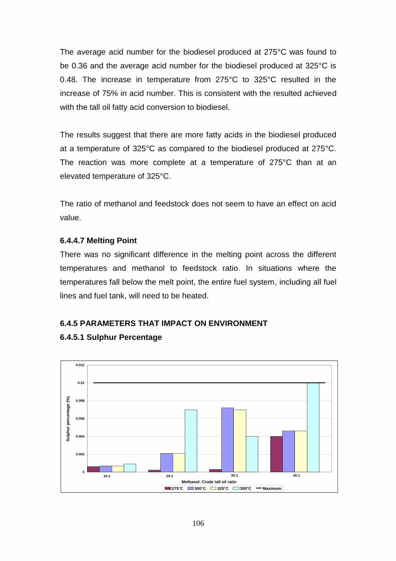
106
The average acid number for the biodiesel produced at 275°C was found to
be 0.36 and the average acid number for the biodiesel produced at 325°C is
0.48. The increase in temperature from 275°C to 325°C resulted in the
increase of 75% in acid number. This is consistent with the resulted achieved
with the tall oil fatty acid conversion to biodiesel.
The results suggest that there are more fatty acids in the biodiesel produced
at a temperature of 325°C as compared to the biodiesel produced at 275°C.
The reaction was more complete at a temperature of 275°C than at an
elevated temperature of 325°C.
The ratio of methanol and feedstock does not seem to have an effect on acid
value.
6.4.4.7 Melting Point
There was no significant difference in the melting point across the different
temperatures and methanol to feedstock ratio. In situations where the
temperatures fall below the melt point, the entire fuel system, including all fuel
lines and fuel tank, will need to be heated.
6.4.5 PARAMETERS THAT IMPACT ON ENVIRONMENT
6.4.5.1 Sulphur Percentage
0
0.002
0.004
0.006
0.008
0.01
0.012
Su
lph
ur
perc
en
tag
e (
%)
275°C 300°C 325°C 350°C Maximum
10:1 20:1 30:1 40:1
Methanol: Crude tall oil ratio

107
There was no correlation between sulphur percentages across the different
temperatures and methanol to feed stock ratios. Since the beginning of 2005,
the sulphur content of fossil diesel has to be below 50 ppm (SAPIA, 2006) as
high sulphur contents in fuels have been associated with negative health
effects and an increased service frequency on vehicles.
6.4.5.2 Ash percentage
There was no correlation in the Ash percentage achieved across the different
temperatures and different methanol to feed ratios. However, the Engine
Manufacturers Association (EMA) recommends an Ash percentage of below
0.01. All Ash percentages measured for the different temperatures were
below 0.01. Higher concentrations of Ash can cause injector tip plugging,
combustion deposits and injection system wear. This is an important factor for
heating value, as heating value decreases with increasing ash content
6.5 Comparison of TOFA and CTO
Below is a comparison for the biodiesel produced from both the feedstocks.
The first part of this section will be a comparison of process parameters, i.e.
time, feedstock to oil ratio and temperature.
0
0.002
0.004
0.006
0.008
0.01
0.012
Ash
perc
en
tag
e
275°C 300°C 325°C 350°C Maximum
10:1 20:1 30:1 40:1
Methanol:crude tall oil ratio

108
6.5.1 Process parameters
Tables 6.5 and 6.6 are the tabular representation of the highest biodiesel yield
achieved and their corresponding feedstock to methanol ratio, temperature
and reaction time for both tall oil fatty acids and crude tall oil.
Table 6.5 Highest biodiesel yield – Tall Oil Fatty Acids (TOFA)
Yield Ratio Temperature (C) Time (min)
83 40:1 325 20
Table 6.6 Highest biodiesel yield – Crude Tall Oil (CTO)
Yield Ratio Temperature (C) Time (min)
69 40:1 350 20
6.5.1.1 Effect of Time
The highest biodiesel yield of 83% was achieved at 20 minutes for the tall oil
fatty acids, whereas a maximum yield of 64% was achieved at the same
reaction time for the crude tall oil.
6.5.1.2 Effect of feedstock: oil ratio
The highest biodiesel yield of 83% was achieved at 40:1 ratio of methanol to
tall oil fatty acids, and the yield of 69% was achieved when crude tall oil was
used.
6.5.1.3 Effect of temperature
The highest biodiesel yield of 83% was achieved at 325°C for the tall oil fatty
acids, and the highest biodiesel yield of 67% was achieved at 350°C when the
feedstock was crude tall oil.
6.5.2 Biodiesel Parameters
6.5.2.1 Iodine numbers
Iodine numbers for both biodiesel products produced from tall oil fatty acids
and crude tall oil were between 95 – 105, which is an acceptable range as per
the Engine Manufacturers Association.

109
6.5.2.2 Cetane number
Cetane numbers for the biodiesel products produced from both the feedstock
above 50, as per Engine Manufacturers Association.
6.5.2.3 Flash point
Flash points for the biodiesel products produced from both the feedstock were
at an acceptable level of above 160.
6.5.2.4 Density
Densities for the biodiesel products that were produced from both tall oil fatty
acids and crude tall oil were within 880 kg/m3 which is recommended by
Engine Manufacturers Association.
6.5.2.5 Acid value
6.5.3 Environmental Parameters
Sulphur and Ash percentages for both the feedstocks were at an acceptable
level of below 0.01.
6.6 Summary
This Chapter presented the results that were achieved from the test work. The
two feedstocks, i.e. tall oil fatty acids and crude tall oil were evaluated
separately. There were three process parameters that were evaluated to
establish if they have any effects on the biodiesel yield produced from the
feedstocks, i.e. reaction time, methanol to feedstock ratio and temperature.
The highest yield of 83% was achieved when feedstock used was tall oil fatty
acid, the process conditions were 20 minutes reaction time, 40:1 methanol to
feedstock ration at 325°C. There was no significant increase after 20 minutes
which would justify running a process longer. This would consume excess
energy without any significant return on biodiesel yield. The temperatures
below and above 325°C didn’t yield a biodiesel yield higher than 83%. The
ratio of 40:1 of methanol to feedstock ratio resulted in the highest yield. The
presence of higher methanol concentration is believed to have assisted with
the conversion rate to biodiesel.
110
The highest yield of 69% was achieved when the feedstock used was crude
tall oil. This yield was achieved at 350°C and 30 minutes. This can be
attributed to the fact that CTO contains rosin and pitch and, together, they are
not converted to biodiesel with the supercritical methanol treatment process.
The performance and environmental indicators of the biodiesel produced were
evaluated. It was concluded that the biodiesel produced from tall oil fatty acid
meets the specifications of the Engine Manufacturers Association. However,
the biodiesel produced from the crude tall oil did not meet the specification of
the Engine Manufacturers Association.

111
CHAPTER 7
ECONOMIC CONSIDERATIONS
7.1 Introduction This Chapter details the economic considerations for the production of
biodiesel from the two feedstocks used for this study. Firstly, this Chapter will
calculate the possible income likely to be generated on the project, based on
the maximum yield achieved on each feedstock. Secondly, this chapter will
discuss the issues that will affect the overall economics of the project, which
will need to be considered. This latter discussion will include the feedstocks
as well as operating parameters.
7.2 Possible income
This table below represents the possible income likely to be generated from
the two feedstocks. The parameters that were used for the calculations below
are those that achieved the maximum yield for both the feedstocks. Table 7.1
indicates the possible income that will be generated from the biodiesel
products generated from both the tall oil fatty acids and crude tall oil.
Based on the tests conducted and reported in the previous Chapter, the
methanol to feedstock ratio that gave the most biodiesel yield was 40:1. The
temperature for the tall oil fatty acids was 325°C, and was 350°C for the
Crude tall oil. Also, the time that gave the highest yield was 20 minutes for the
TOFA and 20 minutes for the crude tall oil.
Table 7.1 – Possible Income from Biodiesel
Feedstock type Tall oil fatty acids (TOFA) Crude tall oil (CTO)
MeoH: feestock ratio 40 40
Temperature (deg C) 325 350
Time (minutes) 20 30
Yield 83 69
Tonnage (tons/month) 356 304
Biodiesel price (R/kg) 8.5 8.5
Monthly income (Rmil/month) R 3,026 R 2,584
Yearly income (Rmil/annum) R 36,312 R 31,008

112
In the previous Chapter, the tall oil fatty acids had the highest yield of 83%
compared to the 76% yield of the crude tall oil. The calculations are shown in
the Appendix 4 and are based on the following parameters:-
400 tons/month of feedstock;
R8.5/litre of biodiesel;
30 days/month; and
12 months/annum.
Based on the calculation above, there is a difference of R5.4 mil/annum. This
is, however, consistent with the low yield on crude tall oil of 76% compared to
tall oil fatty acid of 83%.
7.3 Operating parameters
There are issues that have an influence on the operating parameters that will
need to be considered when the Mill takes the final decision on the project.
There parameters are listed below:-
a) Temperature
The highest yield was achieved at a temperature of 325°C for both the
feedstock. A higher temperature above this point showed no corresponding
increase in the yield, and will result in an increase in steam demand at the
utilities plant.
However, to achieve and maintain a temperature of 325°C, at the current
operation will require a total re-configuration of the utilities plant. These will
include:-
An increased usage of coal and bark; and
Human capital.
b) Time
The optimal reaction time for both the feedstock was 20 minutes. The reaction
time was increased to 50 minutes, but there was no substantial increase in
yield. Ensuring that the reactions are conducted for 20 minutes instead of 50

113
minutes, will increase the plant output which will have a positive impact on the
overall economics of the project as more reactions can be conducted.
c) MeOH
An optimum methanol to feedstock ratio was found to be 40:1 for this study.
Any increase in this ratio showed no significant increase in the yield of the
final product. Methanol is an expensive commodity and, therefore, has a
significant impact on the overall economics of the project.
7.4 Effect of feedstock on economics
This section details the financial impact relating to the two feedstocks that
were utilised for the project. These specific issues were discovered during the
laboratory evaluations, and will have a significant role in the economic
evaluations.
CTO
This feedstock will require no pre-treatment, and will, therefore, be
used in its pure state from the process.
The additional requirement will be for storing the feedstock prior to
pumping into the reactor
However, the maximum yield that was achieved for this feedstock
was 64%. This indicates that there is about 36% of the
unsaponifiable material that was left with the final product.
Therefore, product separation will be required after the conversion
process.
Though there is no pre-treatment required, there is a post-
treatment requirement with this feedstock which will also require
capital investment which in turn impact the income generated by
this project.

114
TOFA
Though the yield is higher than that of crude tall oil feedstock, it
should be noted that the product will have to undergo further
processing prior to converting it into biodiesel. This will require a
huge capital investment and sophisticated equipment including a
distillation column.
However, there will be additional income that will be generated from
the commercialisation of the remaining components after distillation
i.e. rosin and pitch.
7.5 Summary
This Chapter focused on the economic consideration for the project. Based on
the biodiesel yields that were produced, it was established that the revenue
likely to be generated by converting crude tall oil into biodiesel was less
compared to the revenue generated from tall oil fatty acids. This difference in
yield was attributed to the presence of rosin and pitch in the crude tall oil, as
they are not convertible into biodiesel by supercritical methanol treatment.
The influences on operating parameters and the feedstocks on the overall
economics of the project were also evaluated and reported in this Chapter.

115
CHAPTER 8
CONCLUSION
The objective of this study was to investigate the feasibility of converting
crude tall oil and tall oil fatty acids into biodiesel. The global economic
recession that took place between 2007 – 2010, had a profound negative
impact on the operation and the profitability within the pulp and paper
industry. Sappi Tugela reviewed its papermaking process with the view of
establishing if they could be ways of generating extra income within the
process. It was therefore decided that Crude tall oil that is currently being sold
to the third party should be evaluated for biodiesel production.
Crude tall oil and tall oil fatty acids were the two feedstocks that were used
during the study. Crude tall oil is a by-product of a paper making process and
tall oil fatty acid is a larger component of crude tall oil that requires
fractionation distillation to separate from crude tall oil. The latter was therefore
purchased from the third party.
A number of possible conversion procedures were considered for this study to
ascertain if they can be utilized to convert the two feedstocks into biodiesel.
These procedures were base catalysed transesterification, acid-catalysed
esterification; enzyme catalysed reaction as well as supercritical methanol
treatment.
A criteria was then developed to select the best possible procedure and it was
based on the following categories:-
Reaction conditions;
Reaction time;
Ability to convert free fatty acid into alkyl ester;
Final product yield;
Complexity of the process;
Catalyst requirement; and
Pre-treatment requirement.

116
Based on the criteria above, supercritical methanol treatment method was
selected for the experiment because of mostly the high free fatty acid content
within the two feedstocks investigated and the favourable process conditions
(temperature and pressure, no pre-treatment required for the feedstock).
An apparatus which consisted of a 2-litre batch reactor was then set-up to
perform the supercritical methanol treatment conversion procedure. As
indicated earlier, the crude tall oil was sourced from Sappi Tugela and tall oil
fatty acid was purchased from Protea Chemicals.
The testing conditions and the range for the study were determined and the
effects of the following were investigated:
Reaction time;
Reaction temperature; and
Methanol to feedstock ratio.
A maximum yield of 83% for the biodiesel was achieved when the feedstock
investigated was tall oil fatty acid and the yield of 79% was achieved when the
feedstock investigated was crude tall oil. A reaction time of 20 minutes,
reaction temperature of 325°C and the methanol to feedstock ratio of 40:1
were the optimum process conditions for the maximum yields for both the
feedstocks.
It was observed that for both feedstocks that increasing the reaction time
didn’t have any significant increase into the biodiesel yield. This observation
suggested that it was unlikely that there was any conversion at this transitory
heat-up period.
It was also observed that for most of the corresponding temperatures
measured for both the feedstock, the yield was always higher on the tall oil
fatty acids. This difference in yield can be best explained by the fact that
crude tall oil is an unrefined and treated feedstock which was obtained directly
from the process as a by-product. It therefore contains rosin and pitch

117
components which constitute about 30 - 35% of total volume. These
components are not convertible to biodiesel with the supercritical methanol
treatment.
It was also observed that at an equal amount of methanol to feedstock ratio,
the yield was also lower on crude tall oil compared to tall oil fatty acids. This
low yield will play a significant role when storage of the material, energy
required for heating and recovering of the re-usable reactants are being
considered.
Properties of the final biodiesel products from both the feedstocks were tested
to ascertain if they meet the requirements for the Engine Manufacturers
Association. These properties were differentiated as performance and
environmental indicators. Performance indicators were the viscosity, iodine
and cetane numbers, density of the biodiesel, and the environmental
indicators were ash, sulphur and potassium percentages in the final biodiesel
products.
Performance indicators for the tall oil fatty acids met the requirements for the
Engine Manufacturers Association whereas crude tall oil’s performance
indicators didn’t meet the specification. The environmental indicators for both
the final biodiesel products met the Engine Manufacturers Association
specification.
An economic consideration to determine the possible income that is likely to
be generated from both the biodiesel products was performed. It was
established that a yearly income of R 36 million could be realised when the
feedstock used is tall oil fatty acids and R 31 million if the feedstock is crude
tall oil.
Also, the critical issues that will influence the overall economics of the project
when the project is taken to a plant scale were discussed. Though, the
preliminary calculations indicate that there is more revenue to be generated if
the feedstock used if tall oil fatty acid, but the reality of the matter is that tall oil

118
fatty acids will have to undergo further treatment prior to converting into
biodiesel. The costs of pre-treating tall oil fatty acid were not undertaken as it
did not form the scope of this project.
The following were the recommendations that emanated from the
study:-
Should there be a need to conduct further trials in a lab scale, it is
recommended that a minimum 5 litres of reactor be considered. There
was greater difficulty in getting unreacted product after each test, as
there were not sufficient materials left in the reactor for sampling
Due to the difficulties that were experienced in modelling the system
and predict the behaviour, an equilibrium data of vapour/liquid/liquid
should be obtained to determine binary interaction parameters between
each components as well as individual activity co-efficient. Such data
would be invaluable for the prediction of the formation of a single fluid
phase, saving the researcher from the trial and error exercise.
The government has a role to play in ensuring that the biodiesel
business becomes a success. The policies that the government
creates will need to be focused on ensuring that there are incentives
for companies that want to produce biodiesel. The researcher did not
consider these incentives for this study, but they are bound to play a
significant role and they will be largely a part as this initiative
progresses. These incentives includes among other things:-
o Tax incentives;
o Price compensation agreement;
o Carbon credit systems;
o Import tariffs on biofuels; and
o Rebate on the customs duty on imported feedstock.

119
REFERENCES
Anon, D. (2006). “Alternative Fuel Properties of Tall Oil Fatty Acid Methyl
Ester-Diesel Fuel Blends.” Bioresource Technology. 98: 241-246.
Aracil, J., Mercedes, M. and Gemma, V. (2006). “A Comparative Study of
Vegetable Oils for Biodiesel Production in Spain.” Energy & Fuels. 20 (2)
:394-398.
Avela, E. and Holbrom, B. (1971). “Studies on Tall Oil from Pine and Birch
I – Composition of Fatty and Resin Acids in Sulfate Soaps and in Crude
Tall Oil.” ACTA ACADEMIAE ABOENSIS, SER. B 31(13).1-14.
Avela, E. and Holbrom, B. (1971). “Studies on Tall Oil from Pine and Birch
II – Unsaponifiable Constituents in Sulfate Soaps and in Crude Tall Oil.”
ACTA ACADEMIAE ABOENSIS, SER. B 31(16): 1-19.
Ataya, F., Dube, M.A. and Ternan, M. (2006). "Single-Phase and Two-
Phase Base- Catalyzed Transesterification of Canola Oil to Fatty Acid
Methyl Esters at Ambient Conditions." Industrial and Engineering
Chemistry.(45): 5411-5417.
Balat, M. (2005). “Bio-Diesel from Vegetable Oils via Transesterification
in Supercritical Ethanol." 16(1): 45-52.
Bart, C. J. (2005). "Separation Techniques". Additives in Polymers:
industrial analysis and applications. John Wiley and Sons. pp. 212.
Barton, Allan F. M. (1983). Handbook of Solubility Parameters. CRC Press,
Beer, T., and Grant, T. (2009). Comparison of Transport Fuels. Australian
Greenhouse Office, 463 pages,
Biodiesel Education, 2004, http://www.me.istate.edu.biodiesel [02-09-2009]

120
Biodiesel Education, 2004, http://www.me.iastate.edu/biodiesel [02-02-2010]
Boettger, R. (2010). Profitability Improvement initiatives seminar. Sappi
Magazine. South Africa. Vol.17. (2): 17-19
Brown, R. C. (2003). Bio-renewable Resources: Engineering New
Products from Agriculture. Ames, Iowa State Press.
Bryman, A. and Bell, E. (2007). Business Research Methods. London:
McMillan
Canakci, M., and van Gerpen, J. (1999). “Biodiesel Production via Acid
Catalysis.” Transactions of the ASAE, Vol. 42(5): 1203-1210.
Canakci, M, and van Gerpen, J. (2001). "Biodiesel Production from Oils
and Fats with High Free Fatty Acids." Transactions of the ASAE 44 pp:
1429-1436.
Coll, R., William, A. J. and Siddharth, U. (2001). “Conversion of the Rosin
Acid Fraction of Crude Tall Oil into Fuels and Chemicals.” Energy &
Fuels (15): 1166-1172.
Crowl, D. A. and Joseph, F. L. (2002). Chemical Process Safety:
Fundamentals with Applications. 2nd ed. New Jersey: Prentice Hall PTR.
Dalai, A. K. and Mangesh G. K. (2006). “Waste Cooking Oil – An
Economical Source for Biodiesel: A Review.” Industrial and Engineering
Chemistry Research. (45): 2901-2913.
De Bruyn, R. (2008). Status of the Paper Industry in South Africa in 2007.
TAPPSA Journal Volume 4: l27-135.

121
Demirbas, A. (2006)"Biodiesel Production via Non-Catalytic SCF Method
and Biodiesel Fuel Characteristics." Energy Conversion and Management.
47: 2271-2282.
Deul, R. and Franck, E.U. (1978). “Dielectric Behaviour of Methanol and
Related Polar Fluids at High Pressures and Temperatures.” Faraday
Discussions of the Chemical Society. 66: 191-198.
Di Serio, M., Guida, M., Nastasi, E. and Santacesaria, R. T. (2005). "Kinetics
of Oleic Acid Esterification with Methanol in the Presence of
Triglycerides." Industrial and Engineering Chemistry Research. 44: 7978-
7982.
Diasakou, M., Louloudi, A and Papayannakos, N. (1998)"Kinetics of the
Non-Catalytic Transesterification of Soybean Oil." Fuel. 77: 1297-1302.
Du, Z., Liang, G., Buxing, H., Tao, J, Enze, M., and Zhong, T. (2006). "Phase
Equilibria of Methanol-Triolein System at Elevated Temperature and
Pressure." Fluid Phase Equilibria. 239 8-11
Du, Zexue, J., Hu, Zhong T., and Enze M. (2004). “Study of the Solvent
Power of a New Green Solvent: Biodiesel.” Industrial and Engineering
Chemistry Research (43): 7928-7931.
Duncan, J. (2003). Costs of Biodiesel Production, Energy Efficiency and
Conservation Authority.
Dunn, R. O. (2005). "Cold Weather Properties and Performance of
Biodiesel." The Biodiesel Handbook. Ed. Gerhard Knothe, Jurgen Krahl, and
Jon Van Gerpen. Champaign, IL: AOCS P, 91-129.

122
Dykstra, G. J., Pryde, E. H., Selke, A.W. and Sorensen, S. C. (1988). "Diesel
Fuel from Thermal Decomposition of Soybean Oil." JAOCS. 65(11): 1781-
1785.
Encinar, J. M., Gonzalez, J. F., Rodriguez, J. J. and Tejedor A. (2002).
“Biodiesel Fuels from Vegetable Oils: Transesterification of Cynara
cardunculus L. Oils with Ethanol.” Energy & Fuels. 16: 443-450.
Engineering News, 20 October 2006, Biofuels feature, Vol.26 no 40, page
56-64
Friedrick, S. (2003). A world wide review of the commercial production of
Biodiesel, Schriftenreihe Unweltschutz and Ressourcenoekonomie,
Gmehling, J. and Sven, S. (2003). "Esterification of a Fatty Acid by
Reactive Distillation." Industrial and Engineering Chemistry Research. 42
pp: 3612-3619.
Grace, S. (2001). "Vapor-Liquid Equlibria of Triglycerides-Methanol
Mixtures and Their Influence on the Biodiesel Synthesis under
Supercritical Conditions of Methanol." Journal of the Serbian Chemical
Society. 72(1): 13-27.
Grant, R. and Claire, E. (1987). Grant and Hockh's Chemical Dictionary.
McGraw-Hill Book Company.
Griesel, M. (2010). Pretoria research foundation, personal communication
Gupta, M. N., Shweta, S. and Shweta, S. (2004). "Biodiesel Preparation by
Lipase-Catalyzed Transesterification of Jatropha Oil." Energy & Fuels.
(18): 154-159.

123
Haas, M. J. (2005). "Improving the Economics of Biodiesel Production
Through the Use of Low Value Lipids as Feedstocks: Vegetable Oil Soap
stock." Fuel Processing Technology. 86.pp. 1087-1096.
Hansen, C.M. (1999). Hansen Solubility Parameter, A User's Handbook.
CRC Press.
Harshaw, H. W. (2000). The economic valuation of selected non-timber
resources: An examination of valuation and valuation methods and
review of results. PhD Dissertation. University of British Columbia.
Hildebrand, J. H. (1936). The Solubility of Non-Electrolytes. New York:
Reinhold.
Higgins, R.C. and Schall, L.D. (2001). “Corporate Bankruptcy and
Conglomerate Merger,” Journal of Finance (30): 93-113
Hirsch, R. L. (2005). Peaking of World Oil Production: Impacts, Mitigation
& Risk Management. N. E. T. Laboratory, Department of Energy.
Hogan, E., Kriz, D. D., Liu, S., Monnier, J., Tourigny, G. and Wong, A. (1996).
"Production of High Quality Cetane Enhancer from Depitched Tall Oil."
National AICHE Meeting. (Nov 10-15).
Jaayaraj, S., Muraleedharan, C. and Ramadhas, A. S. (2005). “Biodiesel
Production from High FFA Rubber Seed Oil. Fuel 84: 335-340.
Janse, G, and Ottisch, A. (2005). Factors influencing the role of Non-word
Forest Products and Services. Forest Policy and Economics, 7: 309-319.
Jenkins, B. M. (1996). A comment on the optimal sizing of a biomass
utilization facility under constant and variable cost scaling, Biomass and
Bioenergy, 13: 1- 2, 1-9

124
Jennings, W. H. “Seasonal and Geographical Variations in Tall Oil
Composition.” Paper Trade Journal 1948: 137-126.
Jerry, K. (2007). "Fundamentals of Supercritical Fluids." University of
Arkansas, Fayetteville.
Johnson, M. (2006). Evaluating the Potential for Large-Scale Biodiesel
Deployments in a Global Context. MSc thesis, University of Wisconsin-
Madison.
Journey to Forever, 1999, Biodiesel, http://journeytoforever.org/biodiesel,
Kirshner, M. (2005). “Chemical Profile: Tall Oil.” Chemical Market Reporter
October: (34): 21-23
Knothe, G. (2001). Historical Perspective on Vegetable Oil-based Diesel
Fuels. Inform: International News on Fats, Oils, and Related Material.
Knothe, G. (2005). “Cetane Numbers – Heat of Combustion – Why
Vegetable Oils and Their Derivatives are Suitable as a Diesel Fuel.” The
Biodiesel Handbook. Ed. Gerhard Knothe, Jurgen Krahl, and Jon Van
Gerpen. Champaign, IL: AOCS P, 2005.76-79.
Knothe, G., and Kevin R. S. “Lubricity of Components of Biodiesel and
Petrodiesel. The Origin of Biodiesel Lubricity.” Energy & Fuels 19 (2005):
1192-1200.
Kobayashi, T., Nagao, T., Nishida, Y., Pinsirodom, P., Shimada, Y. and
Watanabe, W. (2005). "Production of FAME from Acid Oil Model Using
Immobilized Candida antarctica Lipase." Journal of the American Oil
Chemist's Society. 82 pp: 825-831.

125
Kusdiana, D. and Saka, S. (2004). “Two Step Preparation for Catalyst-Free
Biodiesel Fuel Production.” Applied Biochemistry and Biotechnology. 113-
116: 781-791.
Kusdiana, D., Saka, S. and Yuichiro, W. (2004). "Biodiesel Fuel from
Vegetable Oil by Various Supercritical Alcohols." Applied Biochemistry
and Biotechnology. Pg.113-116 (2004): 793-801.
Kusdiana, D. and Saka, S. (2001). “Methyl Esterification of Free Fatty
Acids of Rapeseed Oil as Treated in Supercritical Methanol.” Journal of
Chemical Engineering of Japan. 34(3): 383-387.
Kusdiana, D., Saka, S. and Yuichiro, W. "Reactivity of Triglycerides and
Fatty Acids of Rapeseed Oil in Supercritical Alcohols." Bioresource
Technology. 91 (2004): 283-287.
Kusdiana, D. and Saka, S. (2001). "Biodiesel Fuel from Rapeseed Oil as
Prepared in Supercritical Methanol." Fuel 80: 225-231.
Kusdiana, D. and Saka, S. (2001). "Kinetics of Transesterification in
Rapeseed Oil to Biodiesel Fuel as Treated in Supercritical Methanol."
Fuel. 80: 693-698.
Labuschagne, J. (2008). The effect of control variables on refining zone
conditions and pulp properties. Paper and Timber Journal 76 (9): 181-188.
Laurie, W. L. (2006). Removal of Polymer Coating with Supercritical
Carbon
Lin, A. and Wai, I. (2003). Alternative Fuel Properties of Tall Oil Fatty Acid
Methyl Ester-Diesel Fuel Blends.” Bioresource Technology. 98(3): 241-246.

126
Madras, G. and Mahesh, N. V. (2007). "Synthesis of Biodiesel from Castor
Oil and Linseed Oil in Supercritical Fluids." Industrial and Engineering
Chemistry Research. 461-6.
Marker, T., and John P. 2006. “Production of Diesel Fuel from
Biorenewable Feedstocks.” U.S. Patent 0264684 A1 (November 23).
Mattingly, B. G. (2005). Optimized Production of Biodiesel From Chicken
Fat Containing Free Fatty Acids. MSc Thesis. University of Arkansas.
McSweeney, E. E. (1987). Tall Oil and Its Uses II. New York, NY: Pulp
Chemicals Association, Inc.
Midwest Biofuels. (1994). Biodiesel Cetane Number Engine Testing
Comparison Cetane Index Number. Midwest Biofuels, USA.
Minami, E. and Saka, S. (2006). “Kinetics of Hydrolysis and Methyl
Esterification for Biodiesel Production in Two-Step Supercritical
Methanol Process.” Fuel. 85: 2479-2483.
Mittelbach, M., and Remschmidt, C. (2005). Biodiesel – the Comprehensive
Handbook, 2nd Edition, Martin Mittelbach, 332 pages
Mncube, D. (2009). Combined high and low consistency refining of
unbleached Kraft pulp. TAPPI Journal 64(7): 59-64.
Nash, P. (2000). Biodiesel Cetane Number Engine Testing Comparison
Cetane Index Number. Midwest Biofuels, USA, pp 101 – 121.
NIST Standard Reference Database. "REF-PROP – Reference Fluid
Thermodynamic & Transport Properties." (2002).
Nitske, W.R. (1965). Rudolph Diesel: Pioneer of the Age of Power.
Norman, Oklahoma, University of Oklahoma Press

127
Nolte, H. (2007). "The potential of liquid biofuels in Sub-Saharan Africa."
Renewable Energy 16(1-4): 1084-1089.
Pahl, G. (2005). Biodiesel: Growing a New Energy Economy. White River
Junction, VT: Chelsea Green Company.
Peterson, C L., and Gregory Möller. (2005). "Biodiesel Fuels:
Biodegradability, Biological and Chemical Oxygen Demand, and
Toxicity." The Biodiesel Handbook. Ed. Gerhard Knothe, Jurgen Krahl, and
Jon Van Gerpen. Champaign, IL: AOCS P. Pp. 145-160.
Pramanik, T. and Tripathi, S. (2005). “Biodiesel: Clean Fuel of the Future.”
Hydrocarbon Processing February, Lewley Publications Inc.
Schlebusch, J. (2007). Challenges experienced within the Pulp and Paper
Industry.
Schulte, M. S. T. (2007). Production of Biodiesel from chicken fat and
crude tall oil with the Supercritical Methanol treatment. MSc Thesis,
Department of Chemical Engineering, Pulp and Paper group. The University
of Arkansas, Trondheim -Norway.
Smook, G.A. (1992). Handbook for pulp and paper technologists. Second
edition. Angus Wilde publications Inc.
Smook, G.A. (1997). Handbook for the pulp and paper technologists.
Second edition. Angus Wilde publications Inc.
South African Petroleum Industry Association, 2006. www.sapia.co.za
Steinigeweg, S. and Gmehling, J. (2003). "Esterification of a Fatty Acid by
Reactive Distillation." Industrial and Engineering Chemistry Research. 42
pp: 3612-3619.

128
TAPPI test method CD; (TAPPI, 2000).
Tat, M. E., Jon Van, Gerpen, and Paul S. W. (2005). “The Production of
Fatty Acid Isopropyl Esters and Their Use as a Diesel Engine Fuel.”
JAOCS 82: 845-849.
Terry, M, and Petri, J. (2006). Production of diesel Fuel from Biorenewable
Feedstock. U.S. Patent 0264684 A1 (november 23).
Van Gerpen, J. (2005). “Biodiesel Processing and Production.” Fuel
Processing Technology 86 (2005): 1097-1107.
Van Gerpen J. et al. 1996. Determining the Influence of Contaminants on
Biodiesel Properties. Lowa State University for The Iowa Soybean
Promotion Board. 1996.
Williams, L. “Biodiesel Lubricity. (2006).” The Biodiesel Handbook. Ed.
Gerhard Knothe, Jurgen Krahl, and Jon Van Gerpen. Champaign, IL: AOCS
P, 2005. 137- 144.
Wong, Al. (2001). “ARBO-TANE™, The Green Diesel Fuel.” Naval Stores
Review. July/August (2001): 14-15.