Embed Size (px)
Citation preview
1
EVALUATIO OF A CAMBER MORPHIG COCEPT BASED O
COTROLLED FLEXIBILITY
Guclu Seber
1, Evren Sakarya
2, Tolga E. Insuyu
3,
Melin Sahin4, Serkan Ozgen
5, Yavuz Yaman
6
Aerospace Engineering Department
Middle East Technical University, Ankara, Turkey
e-mail: [email protected],
Keywords: Morphing Aircraft, Hingeless Control Surface, Finite Element Method, Nonlinear
Contact Analysis, CFD based aerodynamics.
Abstract. In this study, a camber morphing concept is introduced as an alternative to existing
plain flap or aileron type hinged control surfaces used in wings. This concept functions by
flexing the skin panels and imposing a sliding motion in the semi-open secondary wing structure.
Thus, the desired aerodynamic camber is obtained by means of a hingeless control surface. To
investigate the structural aspects, static nonlinear finite element analyses are performed for a
representative morphing wing section by using MSC® NASTRAN. In the models created, double
sided contact surfaces are defined to include the relative motion between parts and to prevent the
separation of the upper and lower skin panels. By using the results obtained from the structural
analyses, contours of the morphed sections are determined. This information is then used to
define the aerodynamic geometries in the CFD based 2D solutions obtained using ANSYS®
FLUENT. In the aerodynamic analyses performed, the aerodynamics coefficients as well as the
chordwise pressure distributions are calculated for several morphed sections. Finally, by taking
into account the effect of pressure loads, the magnitudes of the required actuation forces are
iteratively determined.
omenclature
d = length of the cutout rib (varies between 6 and 10 ��). c = length of the hingeless control surface (selected as 20 ��). w = width of the representative hingeless control surface (selected as 6 ��). s = chordwise distance that is measured from the trailing edge.
TE = wing (or representative section) trailing edge.
∆TE = deflection at the trailing edge measured normal to the chord line (defined positive
down).
d.o.f. = degrees-of-freedom.
MPC = multipoint constraint.
AC = aerodynamic center of the wing section.
c�, c, c� = airfoil lift, pitching moment (w.r.t. AC) and drag coefficients, respectively.
H = aerodynamic moment calculated for the hingeless control surface (6 by 20 ��) about a spanwise axis running along the rear spar.
F = magnitude of the actuation force.
IFASD-2009-182
2
∆H�� = trailing edge deflection of the morphed section that corresponds to zero aerodynamic
moment case.
1 ITRODUCTIO
In morphing wings designs, strategies to alter wing geometries [1,2] or eliminate slots and
surface discontinuities in the control surfaces are employed to adaptively improve the
aerodynamics and the structural response [9] within the complete flight envelope. Fixed wing
geometry is mostly optimized for one design point, whereas the design criteria, i.e. Mach
number, altitude, weight, change during the flight resulting in a decrease in the overall
performance of the wing. Traditional control surfaces used in fixed geometry wings are very
effective at the design condition where they provide the maximum benefit. However, they have
minimal or no effect at the off-design conditions [10]. Mission adaptive wings provide a means
to increase the efficiency criteria by better suiting the changing flight conditions, thus decreasing
the fuel consumption [8]. By employing hingeless control surfaces in the design of mission
adaptive wings, chordwise and spanwise variable camber can be implemented to improve the lift
to drag ratio and to control the spanwise lift distribution, respectively [8]. In most application of
this kind, conventional rib structures are replaced by actuation mechanisms to change the wing
camber. The ‘belt-rib’ [6] approach uses multiple spokes instead of traditional ribs to permit
camber bending of the wing section. Another approach uses ribs made out of rotating segments
that are combined using revolute joints [8]. When the rib is deformed to desired shape, the skin
follows the movement. Other designs are also based on the flexible rib concept where ribs are
rotated to deflect the control surface section of the wing [4]. All these designs employ an open
trailing edge, which reduces the structural stresses by letting the upper and lower skin panels to
slide with respect to each other.
In this paper, a hingeless control surface concept is introduced and numerical analyses are
performed to assess its structural and aerodynamic features. In these analyses several
configurations are evaluated and the corresponding results are presented for comparative
purposes. In the conclusion section, these results are discussed and configurations that are well
balanced are identified.
2 COCEPT DESCRIPTIO
In terms of design philosophy, the concept studied in this paper employs the ideas discussed in
references [4-8] to establish a solution that exploits the structural flexibility to change the wing
aerodynamic camber. To accomplish this goal successfully, the final design is required to be
reliable, lightweight and easy to manufacture using standard off-the-shelf components and
standard engineering materials. In fact, the hingeless control surface will be manufactured
mainly from 0.635 �� thick Al2024-T3 panels.
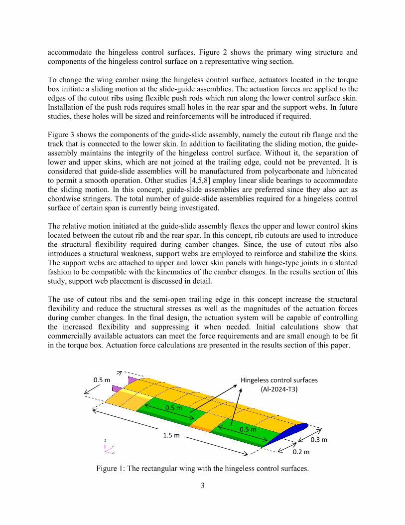
Figure 1 shows the geometry of the rectangular wing with the hingeless control surfaces that is
planned to be manufactured in later stages of the ongoing project. In order to ensure the flight
safety, the unconventional structural modifications, such as the semi-open trailing edge and the
rib cutouts, are only proposed for the hingeless control surfaces. The primary load carrying
structure, i.e. the torque box, is a traditional design, which only requires minor modifications to
3
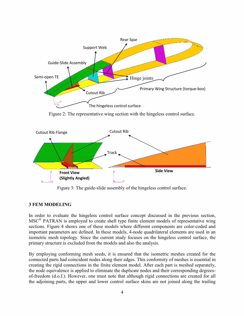
accommodate the hingeless control surfaces. Figure 2 shows the primary wing structure and
components of the hingeless control surface on a representative wing section.
To change the wing camber using the hingeless control surface, actuators located in the torque
box initiate a sliding motion at the slide-guide assemblies. The actuation forces are applied to the
edges of the cutout ribs using flexible push rods which run along the lower control surface skin.
Installation of the push rods requires small holes in the rear spar and the support webs. In future
studies, these holes will be sized and reinforcements will be introduced if required.
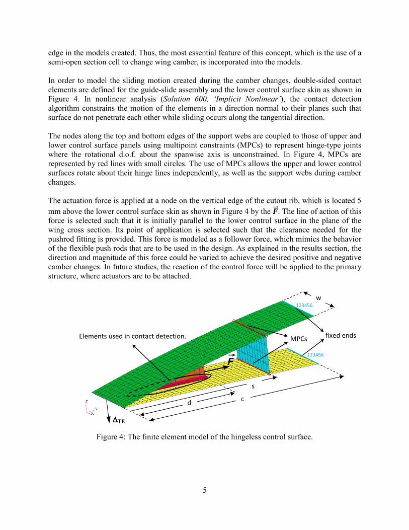
Figure 3 shows the components of the guide-slide assembly, namely the cutout rib flange and the
track that is connected to the lower skin. In addition to facilitating the sliding motion, the guide-
assembly maintains the integrity of the hingeless control surface. Without it, the separation of
lower and upper skins, which are not joined at the trailing edge, could not be prevented. It is
considered that guide-slide assemblies will be manufactured from polycarbonate and lubricated
to permit a smooth operation. Other studies [4,5,8] employ linear slide bearings to accommodate
the sliding motion. In this concept, guide-slide assemblies are preferred since they also act as
chordwise stringers. The total number of guide-slide assemblies required for a hingeless control
surface of certain span is currently being investigated.
The relative motion initiated at the guide-slide assembly flexes the upper and lower control skins
located between the cutout rib and the rear spar. In this concept, rib cutouts are used to introduce
the structural flexibility required during camber changes. Since, the use of cutout ribs also
introduces a structural weakness, support webs are employed to reinforce and stabilize the skins.
The support webs are attached to upper and lower skin panels with hinge-type joints in a slanted
fashion to be compatible with the kinematics of the camber changes. In the results section of this
study, support web placement is discussed in detail.
The use of cutout ribs and the semi-open trailing edge in this concept increase the structural
flexibility and reduce the structural stresses as well as the magnitudes of the actuation forces
during camber changes. In the final design, the actuation system will be capable of controlling
the increased flexibility and suppressing it when needed. Initial calculations show that
commercially available actuators can meet the force requirements and are small enough to be fit
in the torque box. Actuation force calculations are presented in the results section of this paper.
Figure 1: The rectangular wing with the hingeless control surfaces.
0.5 m
0.5 m
0.5 m
0.2 m
Hingeless control surfaces
(Al-2024-T3)
0.3 m
1.5 m
4
Figure 2: The representative wing section with the hingeless control surface.
Figure 3: The guide-slide assembly of the hingeless control surface.
3 FEM MODELIG
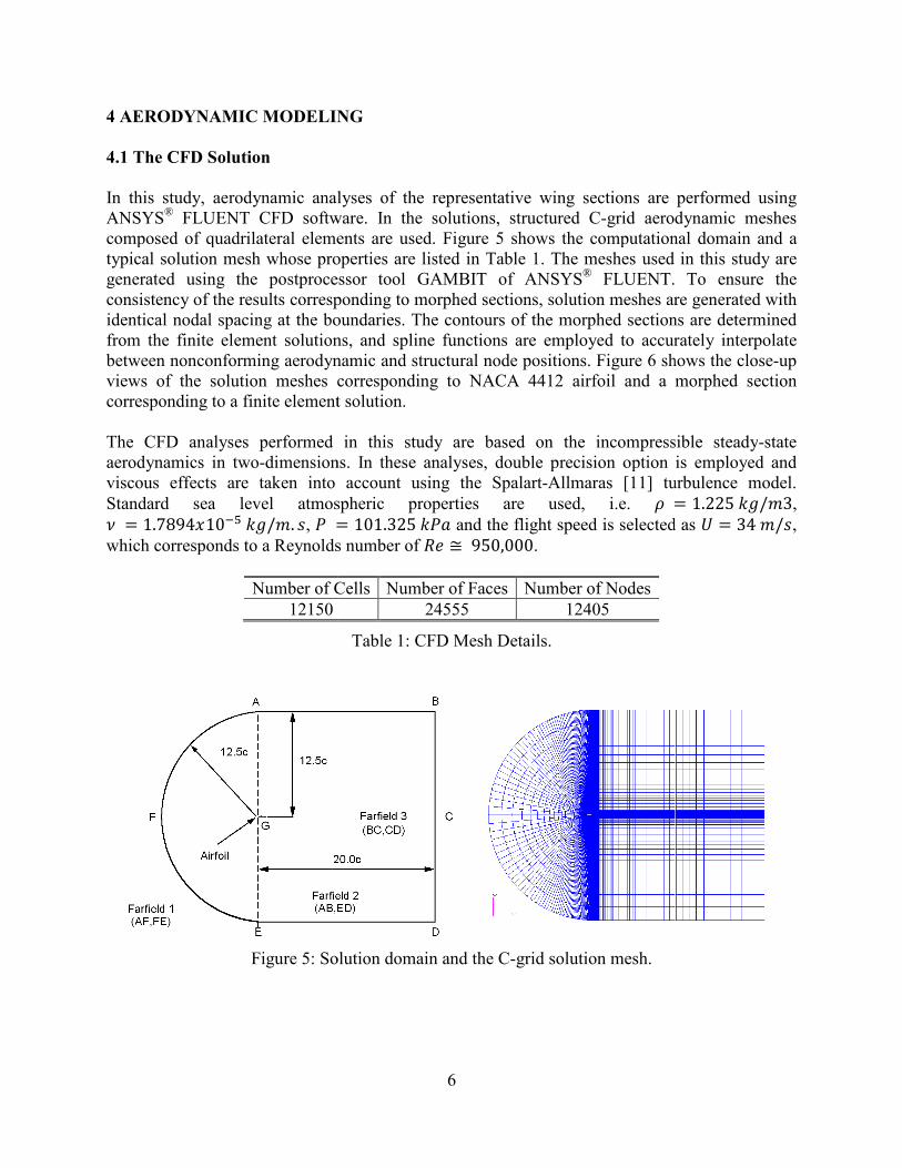
In order to evaluate the hingeless control surface concept discussed in the previous section,
MSC® PATRAN is employed to create shell type finite element models of representative wing
sections. Figure 4 shows one of these models where different components are color-coded and
important parameters are defined. In these models, 4-node quadrilateral elements are used in an
isometric mesh topology. Since the current study focuses on the hingeless control surface, the
primary structure is excluded from the models and also the analysis.
By employing conforming mesh seeds, it is ensured that the isometric meshes created for the
connected parts had coincident nodes along their edges. This conformity of meshes is essential in
creating the rigid connections in the finite element model. After each part is meshed separately,
the node equivalence is applied to eliminate the duplicate nodes and their corresponding degrees-
of-freedom (d.o.f.). However, one must note that although rigid connections are created for all
the adjoining parts, the upper and lower control surface skins are not joined along the trailing
Primary Wing Structure (torque-box)
The hingeless control surface
Rear Spar
Support Web
Cutout Rib
Guide-Slide Assembly
Cutout Rib
Front View
(Slightly Angled)
Side View
Track
Cutout Rib Flange
Semi-open TE Hinge joints
5
edge in the models created. Thus, the most essential feature of this concept, which is the use of a
semi-open section cell to change wing camber, is incorporated into the models.
In order to model the sliding motion created during the camber changes, double-sided contact
elements are defined for the guide-slide assembly and the lower control surface skin as shown in
Figure 4. In nonlinear analysis (Solution 600, ‘Implicit �onlinear’), the contact detection
algorithm constrains the motion of the elements in a direction normal to their planes such that
surface do not penetrate each other while sliding occurs along the tangential direction.
The nodes along the top and bottom edges of the support webs are coupled to those of upper and
lower control surface panels using multipoint constraints (MPCs) to represent hinge-type joints
where the rotational d.o.f. about the spanwise axis is unconstrained. In Figure 4, MPCs are
represented by red lines with small circles. The use of MPCs allows the upper and lower control
surfaces rotate about their hinge lines independently, as well as the support webs during camber
changes.
The actuation force is applied at a node on the vertical edge of the cutout rib, which is located 5
mm above the lower control surface skin as shown in Figure 4 by the ����. The line of action of this force is selected such that it is initially parallel to the lower control surface in the plane of the
wing cross section. Its point of application is selected such that the clearance needed for the
pushrod fitting is provided. This force is modeled as a follower force, which mimics the behavior
of the flexible push rods that are to be used in the design. As explained in the results section, the
direction and magnitude of this force could be varied to achieve the desired positive and negative
camber changes. In future studies, the reaction of the control force will be applied to the primary
structure, where actuators are to be attached.
Figure 4: The finite element model of the hingeless control surface.
fixed ends
d c
F
MPCs Elements used in contact detection.
123456
123456
∆∆∆∆TE
w
s
4 AERODYAMIC MODELIG
4.1 The CFD Solution
In this study, aerodynamic analyses of the representative wing sections are
ANSYS® FLUENT CFD software. In the solutions,
composed of quadrilateral elements are used
typical solution mesh whose properties are listed in Table
generated using the postprocessor tool GA
consistency of the results corresponding to morphed sections
identical nodal spacing at the boundaries.
from the finite element solutions
between nonconforming aerodynamic and structural node positions.
views of the solution meshes corresponding to NACA 4412
corresponding to a finite element solution
The CFD analyses performed in this study
aerodynamics in two-dimensions. In these analyses, double precision option is employed and
viscous effects are taken into account usin
Standard sea level atmospheric
� � 1.7894�10 ! "#/�. %, & �which corresponds to a Reynolds number of
Number of Cells
12150
Figure 5: Solution domain and the C
6
MODELIG
analyses of the representative wing sections are
FLUENT CFD software. In the solutions, structured C-grid aerodynamic meshes
composed of quadrilateral elements are used. Figure 5 shows the computational domain and
whose properties are listed in Table 1. The meshes used in this study
g the postprocessor tool GAMBIT of ANSYS® FLUENT. To ensure the
results corresponding to morphed sections, solution meshes are generated
at the boundaries. The contours of the morphed sections are determined
utions, and spline functions are employed to accurately
between nonconforming aerodynamic and structural node positions. Figure 6 show
solution meshes corresponding to NACA 4412 airfoil and a morphed section
ding to a finite element solution.
The CFD analyses performed in this study are based on the incompressible steady
dimensions. In these analyses, double precision option is employed and
viscous effects are taken into account using the Spalart-Allmaras [11] turbulence model
sea level atmospheric properties are used, i.e. ' �� 101.325 "&( and the flight speed is selected as
which corresponds to a Reynolds number of )* + 950,000.
Number of Cells Number of Faces Number of Nodes
24555 12405
Table 1: CFD Mesh Details.
Solution domain and the C-grid solution mesh.
performed using
grid aerodynamic meshes
shows the computational domain and a
used in this study are
. To ensure the
solution meshes are generated with
The contours of the morphed sections are determined
accurately interpolate
shows the close-up
and a morphed section
incompressible steady-state
dimensions. In these analyses, double precision option is employed and
] turbulence model.
� 1.225 "#/�3, and the flight speed is selected as , � 34 �/%,
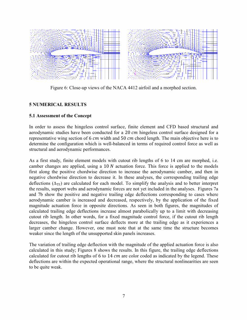
Figure 6: Close-up views of
5 UMERICAL RESULTS
5.1 Assessment of the Concept
In order to assess the hingeless control
aerodynamic studies have been conducted
representative wing section of 6 determine the configuration which is
structural and aerodynamic performance
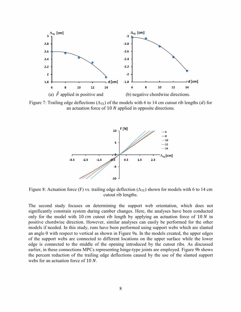
As a first study, finite element models
camber changes are applied, using
first along the positive chordwis
negative chordwise direction to decrease it
deflections (∆TE) are calculated for each model.
the results, support webs and aerodynamic forces are not
and 7b show the positive and negative
aerodynamic camber is increased and decreased
magnitude actuation force in opposite directions
calculated trailing edge deflections
cutout rib length. In other words
decreases, the hingeless control surface deflects more at the trailing edge
larger camber change. However, one must note that at the same time the structure becomes
weaker since the length of the unsupported skin panels increases.
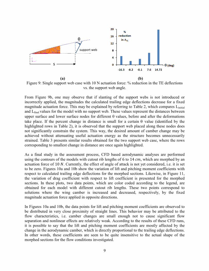
The variation of trailing edge deflection with the
calculated in this study; Figures
calculated for cutout rib lengths
deflections are within the expected operational range
to be quite weak.
7
views of the NACA 4412 airfoil and a morphed section
In order to assess the hingeless control surface, finite element and CFD based
studies have been conducted for a 20 �� hingeless control surface designed for a �� width and 50 �� chord length. The main objective
which is well-balanced in terms of required control force
and aerodynamic performances.
finite element models with cutout rib lengths of 6 to 14 cm are
using a 10 - actuation force. This force is applied along the positive chordwise direction to increase the aerodynamic camber, and then in
direction to decrease it. In these analyses, the corresponding trailing edge
are calculated for each model. To simplify the analysis and to better interpret
aerodynamic forces are not yet included in the analyses.
positive and negative trailing edge deflections corresponding to cases
aerodynamic camber is increased and decreased, respectively, by the application of
in opposite directions. As seen in both figures, the magnitudes of
ated trailing edge deflections increase almost parabolically up to a limit with decreasing
In other words, for a fixed magnitude control force, if the cutout rib
hingeless control surface deflects more at the trailing edge as
However, one must note that at the same time the structure becomes
of the unsupported skin panels increases.
The variation of trailing edge deflection with the magnitude of the applied actuation
8 shows the results. In this figure, the trailing edge
lengths of 6 to 14 �� are color coded as indicated by the legend. These are within the expected operational range, where the structural nonlinearities are
and a morphed section.
finite element and CFD based structural and
hingeless control surface designed for a
The main objective here is to
required control force as well as
of 6 to 14 cm are morphed, i.e.
. This force is applied to the models
e direction to increase the aerodynamic camber, and then in
In these analyses, the corresponding trailing edge
To simplify the analysis and to better interpret
analyses. Figures 7a
corresponding to cases where
e application of the fixed
As seen in both figures, the magnitudes of
increase almost parabolically up to a limit with decreasing
if the cutout rib length
it experiences a
However, one must note that at the same time the structure becomes
actuation force is also
trailing edge deflections
by the legend. These
nonlinearities are seen
8
(a) .� applied in positive and (b) negative chordwise directions.
Figure 7: Trailing edge deflections (∆TE) of the models with 6 to 14 cm cutout rib lengths (/) for an actuation force of 10 - applied in opposite directions.
Figure 8: Actuation force (F) vs. trailing edge deflection (∆TE) shown for models with 6 to 14 cm
cutout rib lengths.
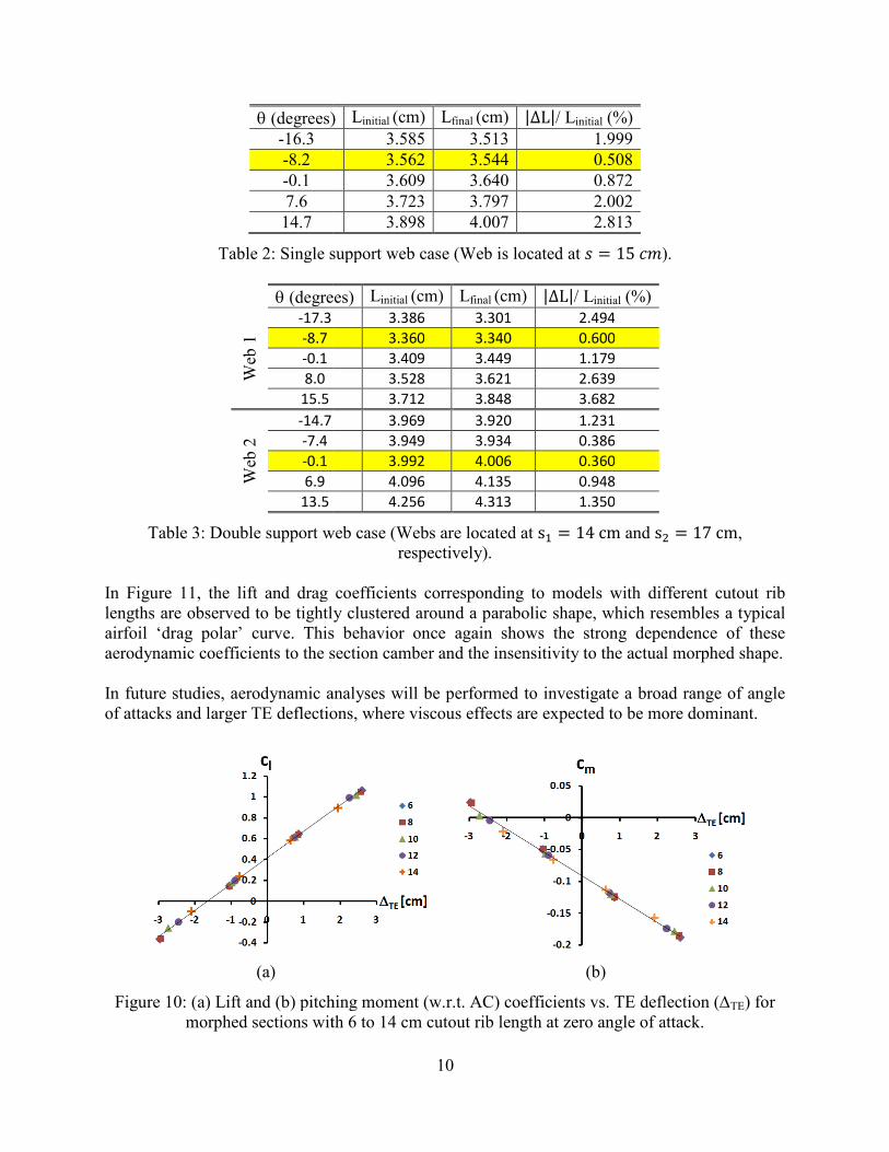
The second study focuses on determining the support web orientation, which does not
significantly constrain system during camber changes. Here, the analyses have been conducted
only for the model with 10 �� cutout rib length by applying an actuation force of 10 - in positive chordwise direction. However, similar analyses can easily be performed for the other
models if needed. In this study, runs have been performed using support webs which are slanted
an angle θ with respect to vertical as shown in Figure 9a. In the models created, the upper edges
of the support webs are connected to different locations on the upper surface while the lower
edge is connected to the middle of the opening introduced by the cutout ribs. As discussed
earlier, in these connections MPCs representing hinge-type joints are employed. Figure 9b shows
the percent reduction of the trailing edge deflections caused by the use of the slanted support
webs for an actuation force of 10 -.
(a) (b)
Figure 9: Single support web case
From Figure 9b, one may observe that if slanting
incorrectly applied, the magnitudes the calculated trailing edge deflections decrease for a fixed
magnitude actuation force. This may be explained by
and Lfinal values for the model with no support web
upper surface and lower surface node
take place. If the percent change in distance is
highlighted rows in Table 2), it is observed that the support web placed along these nodes does
not significantly constrain the system. This way
achieved without attenuating useful actuation energy
strained. Table 3 presents similar results obtained for the two support web case
corresponding to smallest change in distance are
As a final study in the assessment process, CFD based aerodynamic analyses are performed
using the contours of the models with cutout rib lengths of
actuation force of 10 -. Currently, the effect of angle of attack is not yet considered, i.e. to be zero. Figures 10a and 10b show the variation of lift and pitching moment coefficients with
respect to calculated trailing edge deflections for the morphed sections. Likewise, in Figure 11,
the variation of drag coefficient with respect to lift coefficient is presented for the morphed
sections. In these plots, two data points, which are color coded according to the l
obtained for each model with different cutout rib lengths. These two points correspond to
solutions where the wing camber is increased and decreased, respectively, by the fixed
magnitude actuation force applied in opposite directions.
In Figures 10a and 10b, the data points
be distributed in very close proximity of straight lines. This behavior may be attributed to the
flow characteristics, i.e. camber changes are small enough not to cau
separation and nonlinear effects are relatively weak
it is possible to say that the lift and pitching moment coefficients are mostly affected by the
change in the aerodynamic camber, which is
In other words, these coefficients are seen to be quite insensitive to the actual shape of the
morphed sections for the flow conditions investigated.
θ
s
9
(a) (b) case with 10 N actuation force: % reduction in the
vs. the support web angle.
observe that if slanting of the support webs is not introduced
magnitudes the calculated trailing edge deflections decrease for a fixed
force. This may be explained by referring to Table 2, which compares
model with no support web. These values represent the distances between
and lower surface nodes for different θ values, before and after the deformations
If the percent change in distance is small for a certain θ value (identified by the
, it is observed that the support web placed along these nodes does
nstrain the system. This way, the desired amount of camber change may be
useful actuation energy as the structure becomes unnecessarily
strained. Table 3 presents similar results obtained for the two support web case
corresponding to smallest change in distance are once again highlighted.
As a final study in the assessment process, CFD based aerodynamic analyses are performed
using the contours of the models with cutout rib lengths of 6 to 14 ��, which are morphed by an Currently, the effect of angle of attack is not yet considered, i.e.
Figures 10a and 10b show the variation of lift and pitching moment coefficients with
trailing edge deflections for the morphed sections. Likewise, in Figure 11,
the variation of drag coefficient with respect to lift coefficient is presented for the morphed
sections. In these plots, two data points, which are color coded according to the l
obtained for each model with different cutout rib lengths. These two points correspond to
solutions where the wing camber is increased and decreased, respectively, by the fixed
magnitude actuation force applied in opposite directions.
es 10a and 10b, the data points for lift and pitching moment coefficients are observed to
be distributed in very close proximity of straight lines. This behavior may be attributed to the
flow characteristics, i.e. camber changes are small enough not to cause significant flow
nonlinear effects are relatively weak. According to the results of these CFD runs,
it is possible to say that the lift and pitching moment coefficients are mostly affected by the
change in the aerodynamic camber, which is directly proportional to the trailing edge deflections.
In other words, these coefficients are seen to be quite insensitive to the actual shape of the
morphed sections for the flow conditions investigated.
θ
support web
the TE deflections
is not introduced or
magnitudes the calculated trailing edge deflections decrease for a fixed
which compares Linitial
the distances between
before and after the deformations
value (identified by the
, it is observed that the support web placed along these nodes does
the desired amount of camber change may be
as the structure becomes unnecessarily
strained. Table 3 presents similar results obtained for the two support web case, where the rows
As a final study in the assessment process, CFD based aerodynamic analyses are performed
, which are morphed by an
Currently, the effect of angle of attack is not yet considered, i.e. it is set
Figures 10a and 10b show the variation of lift and pitching moment coefficients with
trailing edge deflections for the morphed sections. Likewise, in Figure 11,
the variation of drag coefficient with respect to lift coefficient is presented for the morphed
sections. In these plots, two data points, which are color coded according to the legend, are
obtained for each model with different cutout rib lengths. These two points correspond to
solutions where the wing camber is increased and decreased, respectively, by the fixed
lift and pitching moment coefficients are observed to
be distributed in very close proximity of straight lines. This behavior may be attributed to the
se significant flow
. According to the results of these CFD runs,
it is possible to say that the lift and pitching moment coefficients are mostly affected by the
directly proportional to the trailing edge deflections.
In other words, these coefficients are seen to be quite insensitive to the actual shape of the
θ (degrees)
-16.3
-8.2
-0.1
7.6
14.7
Table 2: Single support web case
θ (degrees)
Web 1
-17.3
-8.7
-0.1
8.0
15.5
Web 2
-14.7
-7.4
-0.1
6.9
13.5
Table 3: Double support web case
In Figure 11, the lift and drag coefficients
lengths are observed to be tightly
airfoil ‘drag polar’ curve. This behavior once again shows the
aerodynamic coefficients to the section camber and the insensitivi
In future studies, aerodynamic analys
of attacks and larger TE deflections, where viscous effects are expected to be more dominant.
(a) (b)
Figure 10: (a) Lift and (b) pitching moment (w
morphed sections with
10
(degrees) Linitial (cm) Lfinal (cm) |∆L|/ Linitial (%) 3.585 3.513 1.999
3.562 3.544 0.508
3.609 3.640 0.872
3.723 3.797 2.002
3.898 4.007 2.813
Table 2: Single support web case (Web is located at % � 15 ��)
(degrees) Linitial (cm) Lfinal (cm) |∆L|/ Linitial (%) 3.386 3.301 2.494
3.360 3.340 0.600
3.409 3.449 1.179
3.528 3.621 2.639
3.712 3.848 3.682
3.969 3.920 1.231
3.949 3.934 0.386
3.992 4.006 0.360
4.096 4.135 0.948
4.256 4.313 1.350
Table 3: Double support web case (Webs are located at s4 � 14 cm and s6
respectively).
lift and drag coefficients corresponding to models with different cutout rib
tightly clustered around a parabolic shape, which resembles a typical
This behavior once again shows the strong dependence of these
aerodynamic coefficients to the section camber and the insensitivity to the actual morphed shape.
analyses will be performed to investigate a broad range of angle
tacks and larger TE deflections, where viscous effects are expected to be more dominant.
(a) (b)
pitching moment (w.r.t. AC) coefficients vs. TE deflection
with 6 to 14 cm cutout rib length at zero angle of attack
).
6 � 17 cm,
with different cutout rib
lic shape, which resembles a typical
dependence of these
ty to the actual morphed shape.
s will be performed to investigate a broad range of angle
tacks and larger TE deflections, where viscous effects are expected to be more dominant.
AC) coefficients vs. TE deflection (∆TE) for
at zero angle of attack.
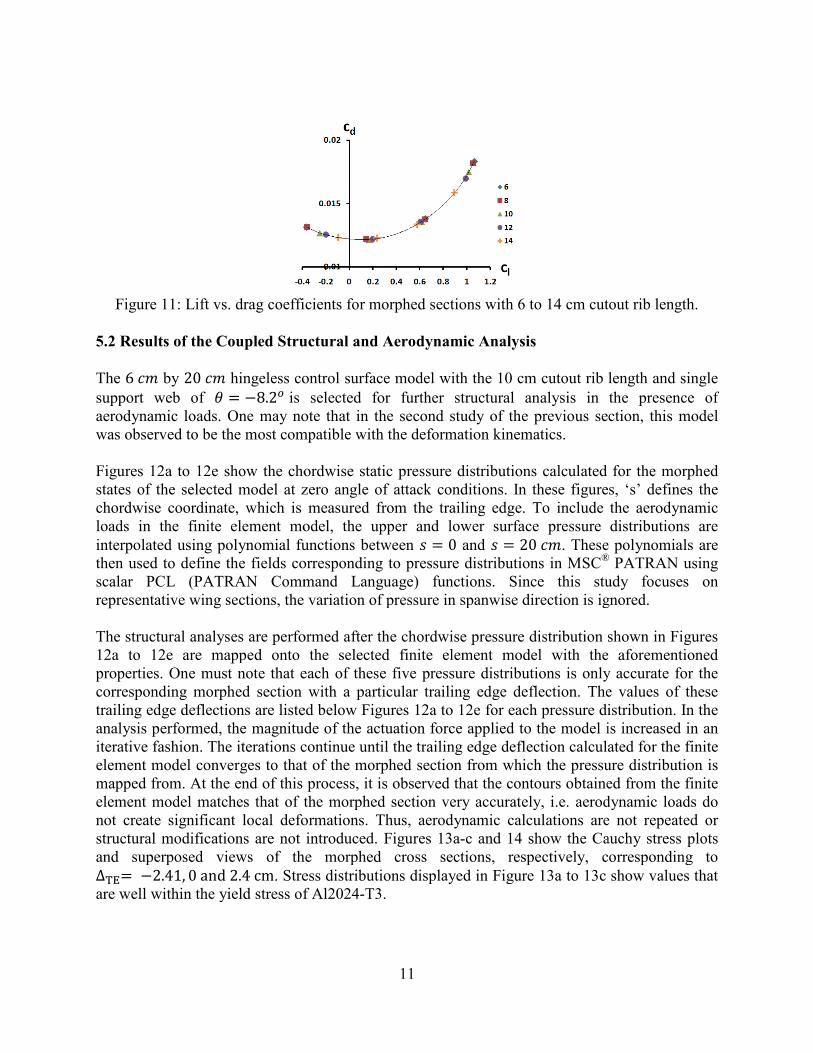
Figure 11: Lift vs. drag coefficient
5.2 Results of the Coupled Structural and Aerodynamic
The 6 �� by 20 �� hingeless control surface support web of 7 � 88.29
is selected
aerodynamic loads. One may note that
was observed to be the most compatible with the deformation kinematics.
Figures 12a to 12e show the chordwise static pressure distributions calc
states of the selected model at zero angle of attack
chordwise coordinate, which is measured
loads in the finite element model
interpolated using polynomial functions
then used to define the fields corresponding to pressure distributions in
scalar PCL (PATRAN Command
representative wing sections, the variation of pressure in spanwise direction is ignored.
The structural analyses are performed
12a to 12e are mapped onto the selected finite element model with the aforementioned
properties. One must note that each of these five pressure distributions is only accurate for the
corresponding morphed section with a particular trailing edge deflection. The values of the
trailing edge deflections are listed below Figures 12a to 12e for each pressure distribution. In the
analysis performed, the magnitude of the actuation force applied to the model is increased in an
iterative fashion. The iterations continue until the tr
element model converges to that of the morphed section from which the pressure distribution is
mapped from. At the end of this process, i
element model matches that of the morphed section very accurately, i.e. aerodynamic loads do
not create significant local deformations. Thus, aerodynamic calculations are not repeated or
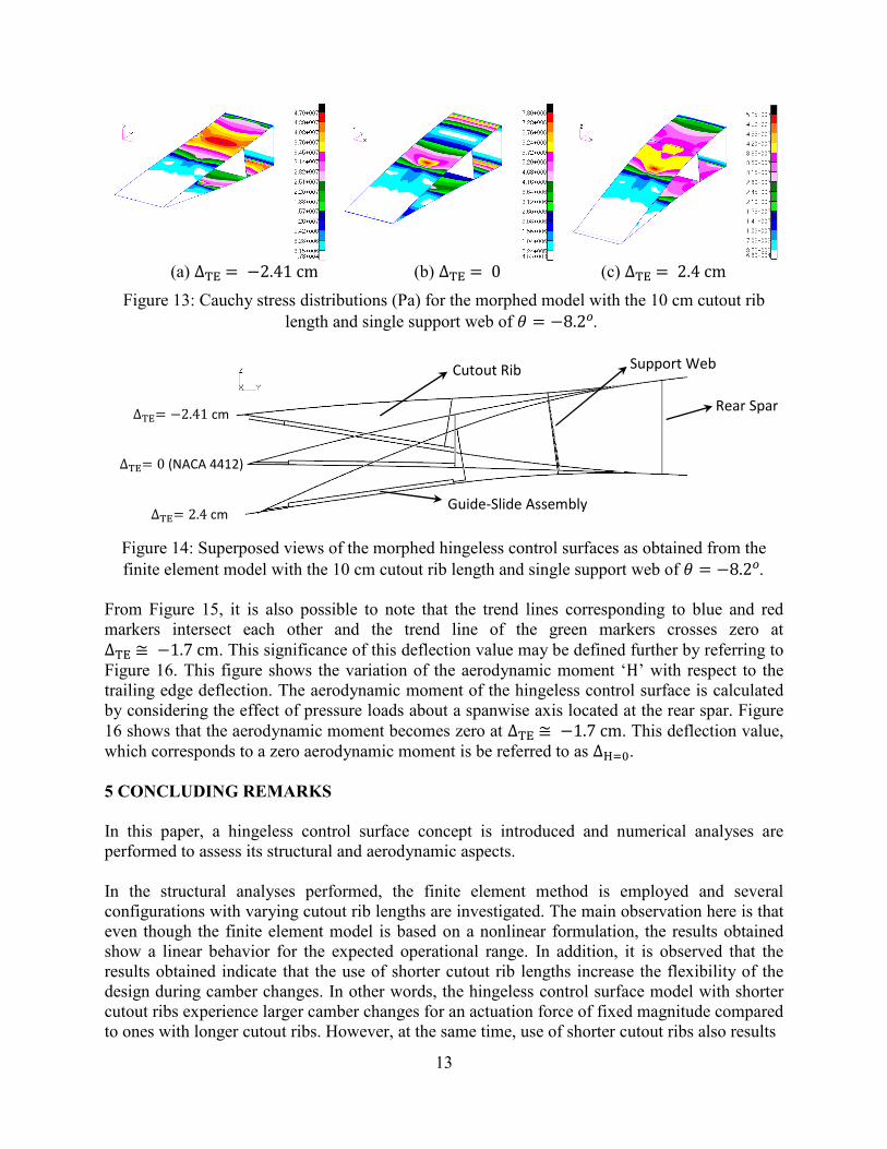
structural modifications are not introduced. Figures 13a
and superposed views of the morphed cross sections, respectively, corresponding to
∆TE� 82.41, 0 and 2.4 cm. Stress distributions displayed in Figure 13a to 13c show values that are well within the yield stress of Al2024
11
Figure 11: Lift vs. drag coefficients for morphed sections with 6 to 14 cm cutout rib
Coupled Structural and Aerodynamic Analysis
hingeless control surface model with the 10 cm cutout rib length and single
is selected for further structural analysis in the presence of
One may note that in the second study of the previous section, this model
compatible with the deformation kinematics.
Figures 12a to 12e show the chordwise static pressure distributions calculated for the morphed
at zero angle of attack conditions. In these figures
chordwise coordinate, which is measured from the trailing edge. To include the aerodynamic
ads in the finite element model, the upper and lower surface pressure distributions are
functions between % � 0 and % � 20 ��. These polynomials are then used to define the fields corresponding to pressure distributions in MSC
®
scalar PCL (PATRAN Command Language) functions. Since this study focuses on
, the variation of pressure in spanwise direction is ignored.
The structural analyses are performed after the chordwise pressure distribution shown
ped onto the selected finite element model with the aforementioned
properties. One must note that each of these five pressure distributions is only accurate for the
corresponding morphed section with a particular trailing edge deflection. The values of the
trailing edge deflections are listed below Figures 12a to 12e for each pressure distribution. In the
analysis performed, the magnitude of the actuation force applied to the model is increased in an
iterative fashion. The iterations continue until the trailing edge deflection calculated for the finite
element model converges to that of the morphed section from which the pressure distribution is
mapped from. At the end of this process, it is observed that the contours obtained from the finite
matches that of the morphed section very accurately, i.e. aerodynamic loads do
not create significant local deformations. Thus, aerodynamic calculations are not repeated or
structural modifications are not introduced. Figures 13a-c and 14 show the Cauchy
and superposed views of the morphed cross sections, respectively, corresponding to
. Stress distributions displayed in Figure 13a to 13c show values that
within the yield stress of Al2024-T3.
cutout rib length.
length and single
n the presence of
in the second study of the previous section, this model
ulated for the morphed
. In these figures, ‘s’ defines the
To include the aerodynamic
r and lower surface pressure distributions are
These polynomials are ® PATRAN using
Since this study focuses on
, the variation of pressure in spanwise direction is ignored.
shown in Figures
ped onto the selected finite element model with the aforementioned
properties. One must note that each of these five pressure distributions is only accurate for the
corresponding morphed section with a particular trailing edge deflection. The values of these
trailing edge deflections are listed below Figures 12a to 12e for each pressure distribution. In the
analysis performed, the magnitude of the actuation force applied to the model is increased in an
ailing edge deflection calculated for the finite
element model converges to that of the morphed section from which the pressure distribution is
the contours obtained from the finite
matches that of the morphed section very accurately, i.e. aerodynamic loads do
not create significant local deformations. Thus, aerodynamic calculations are not repeated or
c and 14 show the Cauchy stress plots
and superposed views of the morphed cross sections, respectively, corresponding to
. Stress distributions displayed in Figure 13a to 13c show values that
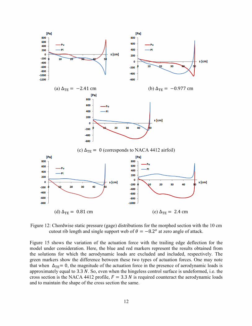
(a) ∆TE � 82.41 cm
(c) ∆TE �
(d) ∆TE � 0.81 cm
Figure 12: Chordwise static pressure
cutout rib length and single support web
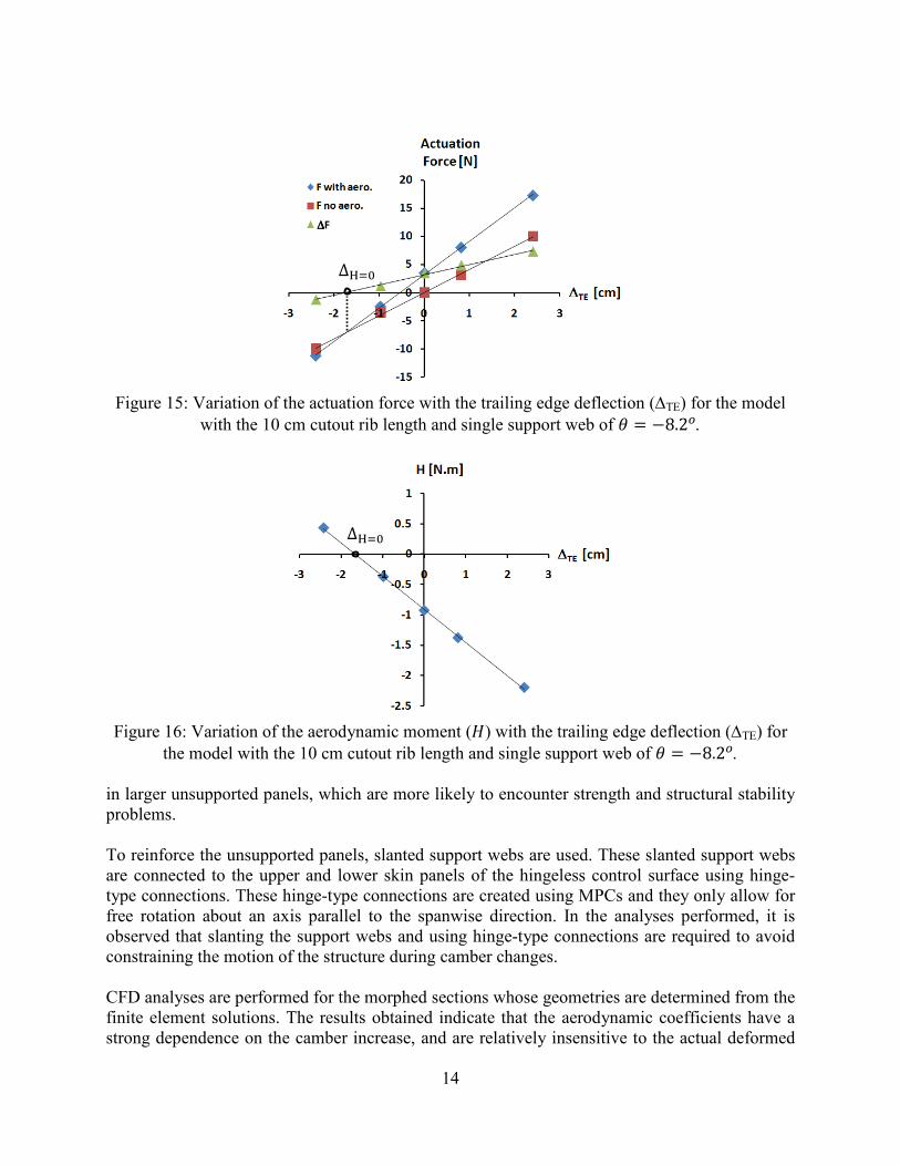
Figure 15 shows the variation of the actuation force with the trailing edge deflection for the
model under consideration. Here, the blue and red markers represent the re
the solutions for which the aerodynamic loads are excluded and included, respectively. The
green markers show the difference between these two types of actuation forces. One may note
that when ∆TE� 0, the magnitude of the actuation fapproximately equal to 3.3 -. So, even when the hingeless control surface is undeformed, i.e. the cross section is the NACA 4412 profile,
and to maintain the shape of the c
12
cm (b) ∆TE � 80.977 cm
� 0 (corresponds to NACA 4412 airfoil)
(e) ∆TE � 2.4 cm
Figure 12: Chordwise static pressure (gage) distributions for the morphed section
cutout rib length and single support web of 7 � 88.29 at zero angle of attack.
Figure 15 shows the variation of the actuation force with the trailing edge deflection for the
model under consideration. Here, the blue and red markers represent the results obtained from
the solutions for which the aerodynamic loads are excluded and included, respectively. The
green markers show the difference between these two types of actuation forces. One may note
, the magnitude of the actuation force in the presence of aerodynamic loads is
. So, even when the hingeless control surface is undeformed, i.e. the
cross section is the NACA 4412 profile, . � 3.3 - is required counteract the aerodynamic loads and to maintain the shape of the cross section the same.
cm
section with the 10 cm
at zero angle of attack.
Figure 15 shows the variation of the actuation force with the trailing edge deflection for the
sults obtained from
the solutions for which the aerodynamic loads are excluded and included, respectively. The
green markers show the difference between these two types of actuation forces. One may note
orce in the presence of aerodynamic loads is
. So, even when the hingeless control surface is undeformed, i.e. the
is required counteract the aerodynamic loads
13
(a) ∆TE � 82.41 cm (b) ∆TE � 0 (c) ∆TE � 2.4 cm
Figure 13: Cauchy stress distributions (Pa) for the morphed model with the 10 cm cutout rib
length and single support web of 7 � 88.29.
Figure 14: Superposed views of the morphed hingeless control surfaces as obtained from the
finite element model with the 10 cm cutout rib length and single support web of 7 � 88.29.
From Figure 15, it is also possible to note that the trend lines corresponding to blue and red
markers intersect each other and the trend line of the green markers crosses zero at
∆TE + 81.7 cm. This significance of this deflection value may be defined further by referring to Figure 16. This figure shows the variation of the aerodynamic moment ‘H’ with respect to the trailing edge deflection. The aerodynamic moment of the hingeless control surface is calculated
by considering the effect of pressure loads about a spanwise axis located at the rear spar. Figure
16 shows that the aerodynamic moment becomes zero at ∆TE + 81.7 cm. This deflection value, which corresponds to a zero aerodynamic moment is be referred to as ∆H��.
5 COCLUDIG REMARKS
In this paper, a hingeless control surface concept is introduced and numerical analyses are
performed to assess its structural and aerodynamic aspects.
In the structural analyses performed, the finite element method is employed and several
configurations with varying cutout rib lengths are investigated. The main observation here is that
even though the finite element model is based on a nonlinear formulation, the results obtained
show a linear behavior for the expected operational range. In addition, it is observed that the
results obtained indicate that the use of shorter cutout rib lengths increase the flexibility of the
design during camber changes. In other words, the hingeless control surface model with shorter
cutout ribs experience larger camber changes for an actuation force of fixed magnitude compared
to ones with longer cutout ribs. However, at the same time, use of shorter cutout ribs also results
∆TE� 82.41 cm
∆TE� 0 (NACA 4412)
∆TE� 2.4 cm
Support Web
Rear Spar
Cutout Rib
Guide-Slide Assembly
14
Figure 15: Variation of the actuation force with the trailing edge deflection (∆TE) for the model
with the 10 cm cutout rib length and single support web of 7 � 88.29.
Figure 16: Variation of the aerodynamic moment (?) with the trailing edge deflection (∆TE) for
the model with the 10 cm cutout rib length and single support web of 7 � 88.29.
in larger unsupported panels, which are more likely to encounter strength and structural stability
problems.
To reinforce the unsupported panels, slanted support webs are used. These slanted support webs
are connected to the upper and lower skin panels of the hingeless control surface using hinge-
type connections. These hinge-type connections are created using MPCs and they only allow for
free rotation about an axis parallel to the spanwise direction. In the analyses performed, it is
observed that slanting the support webs and using hinge-type connections are required to avoid
constraining the motion of the structure during camber changes.
CFD analyses are performed for the morphed sections whose geometries are determined from the
finite element solutions. The results obtained indicate that the aerodynamic coefficients have a
strong dependence on the camber increase, and are relatively insensitive to the actual deformed
∆H��
∆H��
∆∆∆∆F
15
shape. The chordwise pressure distributions obtained in these solutions are used to perform the
final study.
To conduct the final study, the hingeless control surface model with the 10 cm cutout rib length
and single support web is selected due to its well balanced characteristics. In each analysis, the
pressure distribution obtained for a particular CFD analysis is mapped onto the finite element
model. Then iterative solutions are performed to determine the corresponding actuation force
magnitude. The iterations stop when the contour of the deformed model matches that of the
morphed section from which the aerodynamic loads are determined from. From the results
obtained, the deflection corresponding to zero aerodynamic moment is also determined. Cauchy
stress values are also calculated for the hingeless control surface in this study. These values are
seen to be well within yield limit of Al2024-T3, the material from which the hingeless control
surface will be manufactured from.
The hingeless control surface concept studied in this paper relies on a relatively simple idea and
a lightweight structural design, which allows it to be easily manufactured from off the shelf
components and readily available materials. It can be applied to wings with unsymmetrical
airfoils such as the NACA 4412 chosen for this study, as well as symmetrical ones. Also,
integration of this concept into existing wing structures can be done conveniently, since major
modifications are not required in the torque box. From the numerical results, it is observed that
both positive and negative camber changes can be accommodated with similar magnitude
actuation forces, i.e. the structure is not more ‘selective’ towards positive or negative camber
changes. In the expected range of operation, both the structural and the aerodynamic models
predict linear behavior, even though nonlinear effects are fully included in the formulations.
Although further research may involve analyses in the nonlinear range, the use of simplified
linearized models seem promising when the studies are extended to three-dimensional wings for
which optimization and aeroelastic analysis are to be conducted. Another topic to be investigated
in the near future may involve the use of alternative materials for the flexing skin panels, such as
corrugated composites, to lower the actuation force magnitudes further.
In light of the preliminary results obtained in this study, it is believed that the hingeless control
surface concept introduced in this paper has the potential to be used in morphing wing
applications. Future work will be conducted to fully explore this concept and introduce
additional improvements that may be required.
ACKOWLEDGEMET
This research was supported by Turkish Scientific and Technological Research Council through
the project ‘TUBITAK/107M103, Aeroservoelastic Analysis of the Effects of Camber and Twist
on Tactical Unmanned Aerial Vehicle Mission-Adaptive Wings’. The authors gratefully
acknowledge the support given.
16
REFERECES
[1] Bowman, J., Sanders, B., Cannon, B.,Kudva, J., Joshi, S., Weisshaar, T., Development of
Next Generation Morphing Aircraft Structures, 48th AIAA/ASME/ASCE/AHS/ASC Structures,
Structural Dynamics, and Materials Conference, 2007.
[2] Bye, D.R., McClure, P.D., Design of a Morphing Vehicle, 48th AIAA/ASME/ASCE/AHS/
ASC Structures, Structural Dynamics, and Materials Conference, 2007.
[3] Andersen, G.R., Cowan, D.L., Aeroelastic Modeling, Analysis and Testing of a Morphing
Wing Structure, AIAA/ASME/ASCE/AHS/ASC Structure, Structural Dynamics. And Materials
Conference, 2007.
[4] Masarati, M., Quaranta, G., Ricci, S. and Scotti, A., Aeroservoelastic Analysis of Morphing
Controlled Surfaces, IFASD 2007-055, 2007.
[5] Ricci, S., Scotti, A. and Terraneo, M., Design, Manufacturing and Preliminary test Results of
an Adaptive Wing Camber Model, AIAA/ASME/ASCE/AHS/ASC Structures, Structural
Dynamics, and Materials Conference, 2006.
[6] Campanile, L.F. and Anders, S., Aerodynamic and Aeroelastic Amplification in Adaptive
Belt-rib Airfoils, Aerospace Science and Technology, 9(1), 55–63, 2005.
[7] Gern, F.H., Inman, D.J., Kapania, R. K., Structural and Aeroelastic Modeling of General
Planform Wings with Morphing Airfoils, AIAA Journal, 40(4), 628-637, 2002.
[8] Monner, H. S., Realization of an Optimized Wing Camber by Using Formvariable Flap
Structures, Aerospace Science and Technology, 5, 445–455, 2001.
[9] Stanewsky, E., Adaptive Wing and Flow Control Technology, Progress in Aerospace
Sciences, 37, 583–667, 2001.
[10] Stanewsky, E., Aerodynamic Benefits of Adaptive Wing Technology, Aerospace Science
and Technology, 4, 439–452, 2000.
[11] Spalart, P. R., Allmaras, S. R., ‘A One-Equation Turbulence Model for Aerodynamic
Flows’, AIAA Paper 92-0439, 1992