Embed Size (px)
Citation preview

Evaluation of Chemical Agent Resistant Coatings That Are
Exposed to Ultraviolet Radiation
by William S. Lum and James A. Kidd, Jr.
ARL-TN-285 August 2007 Approved for public release; distribution is unlimited.

NOTICES
Disclaimers The findings in this report are not to be construed as an official Department of the Army position unless so designated by other authorized documents. Citation of manufacturer’s or trade names does not constitute an official endorsement or approval of the use thereof. Destroy this report when it is no longer needed. Do not return it to the originator.

Army Research Laboratory Aberdeen Proving Ground, MD 21005-5069
ARL-TN-285 August 2007 Evaluation of Chemical Agent Resistant Coatings That Are
Exposed to Ultraviolet Radiation
William S. Lum and James A. Kidd, Jr. Weapons and Materials Research Directorate, ARL
Approved for public release; distribution is unlimited.

ii
REPORT DOCUMENTATION PAGE Form Approved OMB No. 0704-0188
Public reporting burden for this collection of information is estimated to average 1 hour per response, including the time for reviewing instructions, searching existing data sources, gathering and maintaining the data needed, and completing and reviewing the collection information. Send comments regarding this burden estimate or any other aspect of this collection of information, including suggestions for reducing the burden, to Department of Defense, Washington Headquarters Services, Directorate for Information Operations and Reports (0704-0188), 1215 Jefferson Davis Highway, Suite 1204, Arlington, VA 22202-4302. Respondents should be aware that notwithstanding any other provision of law, no person shall be subject to any penalty for failing to comply with a collection of information if it does not display a currently valid OMB control number. PLEASE DO NOT RETURN YOUR FORM TO THE ABOVE ADDRESS. 1. REPORT DATE (DD-MM-YYYY)
August 2007 2. REPORT TYPE
Final 3. DATES COVERED (From - To)
May 2005–January 2006 5a. CONTRACT NUMBER
5b. GRANT NUMBER
4. TITLE AND SUBTITLE
Evaluation of Chemical Agent Resistant Coatings That Are Exposed to Ultraviolet Radiation
5c. PROGRAM ELEMENT NUMBER
5d. PROJECT NUMBER
AH84 5e. TASK NUMBER
6. AUTHOR(S)
William S. Lum and James A. Kidd, Jr.
5f. WORK UNIT NUMBER
7. PERFORMING ORGANIZATION NAME(S) AND ADDRESS(ES)
U.S. Army Research Laboratory ATTN: AMSRD-ARL-WM-MC Aberdeen Proving Ground, MD 21005-5069
8. PERFORMING ORGANIZATION REPORT NUMBER
ARL-TN-285
10. SPONSOR/MONITOR’S ACRONYM(S)
9. SPONSORING/MONITORING AGENCY NAME(S) AND ADDRESS(ES)
11. SPONSOR/MONITOR'S REPORT NUMBER(S)
12. DISTRIBUTION/AVAILABILITY STATEMENT
Approved for public release; distribution is unlimited.
13. SUPPLEMENTARY NOTES
14. ABSTRACT
The U.S. Army Research Laboratory (ARL) has the lead research and development responsibility for chemical agent resistant coatings (CARC) and manages the relevant specifications that govern the topcoats, primers, and pretreatments for CARC systems. In striving to optimize coating durability and to extend the life cycle of vehicles and weapon systems that use CARC materials, ARL evaluated several CARC topcoats for ultraviolet (UV) resistance. After samples were subjected to UV irradiance in laboratory weathering chambers, several instruments were used to quantify four parameters that indicate the degradation of a material.
15. SUBJECT TERMS
coatings, weathering, durability, QUV exposure
16. SECURITY CLASSIFICATION OF: 19a. NAME OF RESPONSIBLE PERSON William S. Lum
a. REPORT UNCLASSIFIED
b. ABSTRACT UNCLASSIFIED
c. THIS PAGE UNCLASSIFIED
17. LIMITATION OF ABSTRACT
UL
18. NUMBER OF PAGES
22
19b. TELEPHONE NUMBER (Include area code) (410) 306-0706
Standard Form 298 (Rev. 8/98) Prescribed by ANSI Std. Z39.18
iii
Contents
List of Figures iv
List of Tables v
Acknowledgments vi
1. Introduction 1
2. Procedure 1 2.1 Parameters for Accelerated Weathering..........................................................................1
2.2 Sample Preparation..........................................................................................................3
2.3 Performance Testing for Color Fastness .........................................................................4
2.4 Performance Testing of Specular Gloss ..........................................................................4
3. Results 5
4. Conclusions 10
5. References 12
Distribution List 13

iv
List of Figures
Figure 1. CARC topcoats, color change from initial value.............................................................7 Figure 2. CARC topcoats, color change from center of ellipse. .....................................................8 Figure 3. CARC topcoats, color change from initial value for green and tan. ...............................8 Figure 4. CARC topcoats, color change from initial value for brown and black. ..........................9 Figure 5. CARC topcoats, gloss at 60°. ..........................................................................................9 Figure 6. CARC topcoats, gloss at 85°. ........................................................................................10

v
List of Tables
Table 1. Exposure schedule for UV radiation.................................................................................2 Table 2. Coating requirements for specular gloss...........................................................................5 Table 3. Averaged performance measurement of system 0003, green 383. ...................................5 Table 4. Averaged performance measurement system 3063, tan 686A. ........................................6 Table 5. Averaged performance measurement system 3083, brown 383. ......................................6 Table 6. Averaged performance measurement, system 3073, black 37030....................................6 Table 7. Performance of CARC topcoats subjected to UV irradiance .........................................10
vi
Acknowledgments
Pauline M. Smith, a research chemist in the Materials Applications Branch of the U.S. Army Research Laboratory, reviewed the document for both editorial and technical content. Thomas A. Considine, a contractor with the Oak Ridge Institute for Science and Education, assisted with the figures.

1
1. Introduction
Approximately 99% of solar radiation at the surface of the Earth is within the wavelength region of 295–3000 nm. This report focuses on the exposure of several military coatings to light with a wavelength that is shorter than that for visible light. Ultraviolet (UV) radiant energy is light with a wavelength that ranges from ~295 to 385 nm. Although UV light comprises only 3.3% of the wavelength region for solar radiation, it represents the most energy-intensive region; generally, photon energy is inversely proportional to the wavelength. Short wavelength light can have sufficient energy to break chemical bonds (1, 2).
Since the beginning of Fiscal Year 1985, U.S. Army Regulation 750-1 mandates the use of chemical agent resistant coatings (CARC) systems on all tactical equipment. Additionally, U.S. Army doctrine directs coatings research and development towards three primary principles: survivability, durability (meet or exceed operational requirements and resistance to corrosion and ultraviolet exposure), and environmental compliance.
The U.S. Army Research Laboratory (ARL) is the lead research and development activity for (CARC) and is the approving authority of CARC products for the Department of Defense (DOD). A typical CARC system consists of a pretreatment, primer, and topcoat. The overall coating system is formulated to provide proper substrate protection while maintaining minimal detection in the visible (~385–780 nm) and near infrared (~780–1400 nm) range (2).
Compositionally, a CARC topcoat is formulated to have ~44% primary pigments and inorganic extenders, 24% resins, 30% solvent, and 2% additives. Recent advances in raw material development have lead formulators to change from inorganic to polymeric-based extenders in order to enhance the barrier properties of the topcoat. These improved formulations help to reduce the cost of material degradation for the DOD. Additionally, recent air pollution regulations have required reformulation of the coating’s solvent content to reduce the emission of hazardous air pollutants (HAPs). The primary focus of this research effort is quantifying the affect of these changes in composition on the durability of CARC.
2. Procedure
2.1 Parameters for Accelerated Weathering
Accelerated weathering is an important screening practice that is used to ensure that newly developed formulations will adequately provide the necessary performance with respect to colorfastness, retention of low gloss, and long-term protective film integrity. Performance data
2
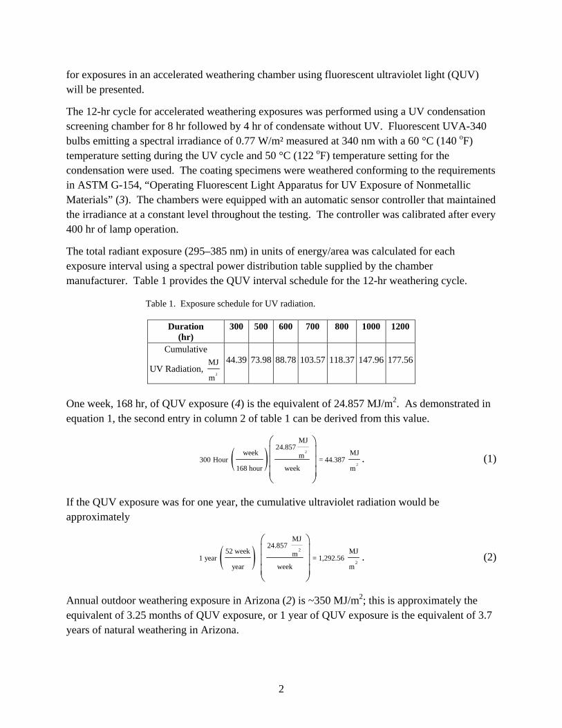
for exposures in an accelerated weathering chamber using fluorescent ultraviolet light (QUV) will be presented.
The 12-hr cycle for accelerated weathering exposures was performed using a UV condensation screening chamber for 8 hr followed by 4 hr of condensate without UV. Fluorescent UVA-340 bulbs emitting a spectral irradiance of 0.77 W/m² measured at 340 nm with a 60 °C (140 oF) temperature setting during the UV cycle and 50 °C (122 oF) temperature setting for the condensation were used. The coating specimens were weathered conforming to the requirements in ASTM G-154, “Operating Fluorescent Light Apparatus for UV Exposure of Nonmetallic Materials” (3). The chambers were equipped with an automatic sensor controller that maintained the irradiance at a constant level throughout the testing. The controller was calibrated after every 400 hr of lamp operation.
The total radiant exposure (295–385 nm) in units of energy/area was calculated for each exposure interval using a spectral power distribution table supplied by the chamber manufacturer. Table 1 provides the QUV interval schedule for the 12-hr weathering cycle.
Table 1. Exposure schedule for UV radiation.
Duration (hr)
300 500 600 700 800 1000 1200
Cumulative
UV Radiation, 2
MJ
m
44.39
73.98
88.78
103.57
118.37
147.96
177.56
One week, 168 hr, of QUV exposure (4) is the equivalent of 24.857 MJ/m2. As demonstrated in equation 1, the second entry in column 2 of table 1 can be derived from this value.
( ) 2
2
MJ24.857
week MJm300 Hour = 44.387 168 hour week m
⎛ ⎞⎜ ⎟⎜ ⎟⎜ ⎟⎝ ⎠
. (1)
If the QUV exposure was for one year, the cumulative ultraviolet radiation would be approximately
( ) 2
2
MJ24.857
52 week MJm1 year = 1,292.56 year week m
⎛ ⎞⎜ ⎟⎜ ⎟⎜ ⎟⎝ ⎠
. (2)
Annual outdoor weathering exposure in Arizona (2) is ~350 MJ/m2; this is approximately the equivalent of 3.25 months of QUV exposure, or 1 year of QUV exposure is the equivalent of 3.7 years of natural weathering in Arizona.

3
For Arizona, the average direct-beam UV irradiance, based on a diurnal cycle, can be estimated as follows:
( ) ( )2 2
2
UV
MJ MW350 second
year hour daym m MJyear 365 day 3,600 second 24 hour
m
I .=
⎡ ⎤⎢ ⎥⎛ ⎞ ⎛ ⎞⎜ ⎟⎜ ⎟ ⎢ ⎥ ⎝ ⎠⎝ ⎠ ⎢ ⎥⎣ ⎦
(3)
( )6
2 2UV
350 W 1 1 W 1 10 = 11.10
365 m 3,600 24 mI = ⎛ ⎞⎡ ⎤ ⎛ ⎞
⎜ ⎟⎜ ⎟⎢ ⎥⎣ ⎦ ⎝ ⎠⎝ ⎠. (4)
Annual outdoor weathering exposure in southern Florida (2) is ~280 MJ/m2; this is approximately the equivalent of 2.56 months of QUV exposure, or 1 year of QUV exposure is the equivalent of 4.6 years of natural weathering in southern Florida.
For southern Florida, the average direct-beam UV irradiance, based on a diurnal cycle, can be estimated as follows:
( ) ( )2 2
2
2
UV
MJ MW280 second
year hour day Wm m = 8.88 MJyear 365 day 3,600 second 24 hour m
m
I =
⎡ ⎤⎢ ⎥⎛ ⎞ ⎛ ⎞⎜ ⎟⎜ ⎟ ⎢ ⎥ ⎝ ⎠⎝ ⎠ ⎢ ⎥⎣ ⎦
. (5)
These values for Arizona and Florida can be compared to the direct-beam UV irradiance that is delivered in the QUV chamber. Although the QUV uses a 12-hr cycle, for this calculation a 24 hour/day must be used.
( )
2 2
2
UV
MJ MW24.857 second hour day weekm m
MJweek 3,600 second 24 hour 7 daym
I⎡ ⎤⎢ ⎥ ⎛ ⎞⎛ ⎞ ⎛ ⎞= ⎜ ⎟⎜ ⎟ ⎜ ⎟⎢ ⎥ ⎝ ⎠⎝ ⎠ ⎝ ⎠⎢ ⎥⎣ ⎦
. (6)
( )6
2 2UV W 1 1 1 W
1 10 = 41.10 m 3,600 24 7 m
24.857I ⎛ ⎞⎡ ⎤ ⎛ ⎞ ⎛ ⎞= ⎜ ⎟ ⎜ ⎟⎜ ⎟⎢ ⎥⎣ ⎦ ⎝ ⎠ ⎝ ⎠⎝ ⎠. (7)
This value for direct-beam UV irradiance is 3.7 times as intense as that for Arizona and 4.6 times that for southern Florida.
For a topcoat that is exposed to intense irradiance to maintain its design camouflage properties, both the color change and the specular gloss must be minimized.
2.2 Sample Preparation
Two cold rolled steel panels, 4 × 12 in, with a zinc phosphate pretreatment and epoxy primer were used for each manufacturer’s color. After each panel was sprayed and the coating had cured, the panels were cut in half transversely and then trimmed to 3 × 6 in size so that they

4
could be placed into the weathering chamber. Therefore, four separate panels represented each color from all suppliers. Four different color topcoats were tested. As specified in paragraphs 4.6.11 and 4.6.12 of MIL-DTL-53039B (5), all panels were sprayed to a dry film thickness of 1.8–2.2 mils and cured at room temperature for 7 days.
2.3 Performance Testing for Color Fastness
Representative results for each of the four colors are tabulated using National Bureau of Standards (NBS) color difference vs. total hours of exposure; all of the results for color change are graphed. Samples were tested for a baseline value at the seven successive intervals shown in table 1. A sample is considered to be acceptable if the color change from the initial value or the change from the center of the ellipse does not exceed 2.5 NBS units after 800 hr of accelerated weathering. This requirement is summarized in paragraph 3.6.11 of MIL-DTL-53039B for color change limit is used for moisture cure polyurethanes. To collect data beyond the required period of exposure, samples were tested for an additional 400 hr.
2.4 Performance Testing of Specular Gloss
The color and infrared reflectance measurements were performed using a visible/near-IR spectrophotometer equipped with an 8 in diameter integrating sphere and a halogen tungsten light source. The readings were taken in accordance with the requirements in MIL-DTL-53039B. The spectrophotometer was calibrated before each series of analyses using the manufacturer’s standard color tile (serial no. 2621).
Gloss is associated with the capacity of a surface to reflect more light in some directions than in others. The directions associated with mirror or specular reflection normally have the highest reflectances. The gloss scale is such that the larger the number, the higher the gloss. A highly polished, plane, black glass with a specified refractive index is assigned a specular gloss of 100 for each geometry; this is the maximum value for the scale. If a surface is devoid of reflectance, the specular gloss is zero. The test method for specular gloss is contained in ASTM D-523 (6). Gloss measurements were made in accordance with ASTM D-523 using a Haze-Gloss Reflectometer*, Model 4606. The measurements were taken at two different angle geometries, 60° and 85°. The 60° geometry is used for comparing most specimens. The 85° geometry is for comparing the sheen or near-grazing shininess of specimens; typically, it is used when specimens have 60° gloss values that are <10. Using the manufacturer’s standard reference tile (serial no. 9017715), the instrument’s performance was verified for accuracy and consistency before each series of measurements. A series consists of one color for each manufacturer measured for both angles; therefore, the instrument was verified for a total of nine groups of gloss measurements.
* Haze-Gloss Reflectometer is a registered trademark of BYK-Gardner, Columbia, MD.

5
These environmentally related failures are broadly characterized in two different ways: one as minor, such as appearance changes (color loss/fade), and the other as catastrophic, such as film degradation (substrate corrosion and chemical debonding). The applicable requirements from MIL-DTL-53039B for specular gloss are listed in table 2.
Table 2. Coating requirements for specular gloss.
Maximal Allowed ValueColor60o 85o, Sheen
Green383
1.0 3.5
Tan 686A
1.6 4.0
Brown383
1.0 3.5
Black37030
1.0 3.5
3. Results
The results for this evaluation are presented in tables 3–6 for representative samples of four different camouflage colors. The numerical designation for color corresponds with paragraph 1.2.2 in MIL-DTL-53039B and the qualified products list for the same document. The numerical designation for the system is an ARL code that indicates the manufacturer. For the third column in each table, the reference point at the center of each ellipse is zero; each value, including the initial reading, represents a concentric ellipse that indicates the change from the reference point. One data point is collected from each of the four panels described in section 2.2; therefore, each averaged value is the mean of four data points.
Table 3. Averaged performance measurement of system 0003, green 383.
Average Performance Measurement Color Change, NBS Units Specular Gloss Duration of
Exposure (hr)
Change From Initial Value
Change From Center of Ellipse 60° 85°
Initial 0.00 1.88 0.5 2.2 300 0.55 1.93 0.5 1.6 500 0.37 1.99 0.5 1.7 600 0.59 1.96 0.5 1.7 700 0.47 2.03 0.5 1.7 800 0.42 2.12 0.5 1.7 1000 0.58 2.24 0.5 1.9 1200 0.99 2.53 0.6 2.8

6
Table 4. Averaged performance measurement system 3063, tan 686A.
Average Performance Measurement Color Change, NBS Units Specular Gloss Duration of
Exposure (hr)
Change From Initial Value
Change From Center of Ellipse 60° 85°
Initial 0.00 0.70 1.5 1.4 300 0.16 0.79 1.3 1.2 500 0.21 0.87 1.2 1.2 600 0.53 1.16 1.2 1.2 700 0.76 1.43 1.2 1.2 800 1.36 1.68 1.2 1.2 1000 2.56 3.19 1.2 1.2 1200 3.98 4.58 1.4 1.9
Table 5. Averaged performance measurement system 3083, brown 383.
Average Performance Measurement Color Change, NBS Units Specular Gloss Duration of
Exposure (hr)
Change From Initial Value
Change From Center of Ellipse 60° 85°
Initial 0.00 0.60 1.6 1.9 300 0.18 0.68 1.3 1.3 500 0.19 0.78 1.3 1.4 600 0.27 0.85 1.3 1.4 700 0.38 0.96 1.3 1.5 800 0.50 1.05 1.3 1.5 1000 0.92 1.49 1.2 1.5 1200 1.88 2.42 1.5 2.2
Table 6. Averaged performance measurement, system 3073, black 37030.
Average Performance Measurement Color Change, NBS Units Specular Gloss Duration of
Exposure (hr)
Change From Initial Value
Change From Center of Ellipse 60° 85°
Initial 0.00 0.35 0.2 1.3 300 1.04 1.26 0.3 1.0 500 1.21 1.37 0.3 1.0 600 2.64 2.80 0.4 1.0 700 2.82 2.98 0.4 1.0 800 3.04 3.18 0.4 1.1 1000 4.20 4.33 0.4 1.0 1200 4.65 4.77 0.5 1.6

7
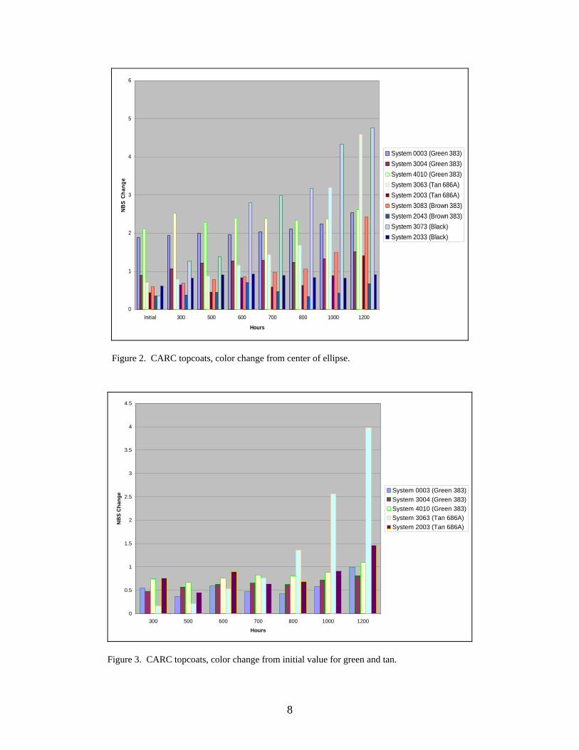
To avoid redundancy, all of the collected data is not shown in the previous four tables. Data was taken on green 383 from three selected manufacturers. Two suppliers provided the samples of tan 686A, brown 383, and black 37030. The results of all of the tests are summarized in figures 1–6. As indicated for the previous tables, each result is the mean of four data points.
0
0.5
1
1.5
2
2.5
3
3.5
4
4.5
5
300 500 600 700 800 1000 1200
Hours
NBS
Chan
ge
System 0003 (Green 383)System 3004 (Green 383)System 4010 (Green 383)System 3063 (Tan 686A)System 2003 (Tan 686A)System 3083 (Brown 383)System 2043 (Brown 383)System 3073 (Black)System 2033 (Black)
Figure 1. CARC topcoats, color change from initial value.
8
0
1
2
3
4
5
6
Initial 300 500 600 700 800 1000 1200
Hours
NBS
Chan
ge
System 0003 (Green 383)System 3004 (Green 383)System 4010 (Green 383)System 3063 (Tan 686A)System 2003 (Tan 686A)System 3083 (Brown 383)System 2043 (Brown 383)System 3073 (Black)System 2033 (Black)
Figure 2. CARC topcoats, color change from center of ellipse.
0
0.5
1
1.5
2
2.5
3
3.5
4
4.5
300 500 600 700 800 1000 1200
Hours
NB
S C
hang
e System 0003 (Green 383)System 3004 (Green 383)System 4010 (Green 383)System 3063 (Tan 686A)System 2003 (Tan 686A)
Figure 3. CARC topcoats, color change from initial value for green and tan.

9
0
0.5
1
1.5
2
2.5
3
3.5
4
4.5
5
300 500 600 700 800 1000 1200
Hours
NBS
Cha
nge
System 2043 (Brown 383)
System 3083 (Brown 383)
System 2033 (Black)
System 3073 (Black)
Figure 4. CARC topcoats, color change from initial value for brown and black.
0
0.2
0.4
0.6
0.8
1
1.2
1.4
1.6
1.8
Initial 300 500 600 700 800 1000 1200
Hours
NBS
Chan
ge
System 0003 (Green 383)System 3004 (Green 383)System 4010 (Green 383)System 3063 (Tan 686A)System 2003 (Tan 686A)System 3083 (Brown 383)System 2043 (Brown 383)System 3073 (Black)System 2033 (Black)
Figure 5. CARC topcoats, gloss at 60°.

10
0
0.5
1
1.5
2
2.5
3
3.5
Initial 300 500 600 700 800 1000 1200
Hours
NBS
Chan
ge
System 0003 (Green 383)System 3004 (Green 383)System 4010 (Green 383)System 3063 (Tan 686A)System 2003 (Tan 686A)System 3083 (Brown 383)System 2043 (Brown 383)System 3073 (Black)System 2033 (Black)
Figure 6. CARC topcoats, gloss at 85°.
4. Conclusions
None of the coatings that were tested sustained a catastrophic failure. QUV results demonstrated significant consistency for different colors from several manufacturers. Using the requirements that are specified in section 2.3 and in table 2, the performance of all of the tested topcoats is summarized in table 7.
Table 7. Performance of CARC topcoats subjected to UV irradiance.
Color Change Specular Gloss
Color Manufacturer From Initial
Value From Center
of Ellipse 60o 85o 0003 P P P P 3004 P P P P
Green 383
4010 P P P P 3063 P P P P Tan
686A 2003 P P P P 3083 P P F P Brown
383 2043 P P P P 3073 F F P P Black
37030 2033 P P P P Notes: P = Pass
F = Fail

11
Overall, all of the tested topcoats performed very well in their resistance to ultraviolet light; generally the camouflage properties of these topcoats were not significantly diminished. Of 36 performance results, only 8.3% did not meet the specified criteria. Only brown 383 from manufacturer 3083 did not pass the specular gloss requirement of 1.0 for 60°; it exceeded this value for the entire duration of the test. Two of the failures were for black 37030 from manufacturer 3073; between 500 and 600 hr of exposure, it was unacceptable for both of the color change requirements. It was acceptable for both categories of specular gloss through 1200 hr of exposure. All of the topcoats passed the 85° requirement for specular gloss.
This evaluation validated QUV testing as a screening test for CARC topcoats that must meet the requirements of MIL-DTL-53039B regarding color change and specular gloss. As indicated in section 2.1, QUV accelerated weathering should always be correlated with outdoor testing in geographical areas with strong irradiance such as Arizona and Florida.
12
5. References
1. The Eppley Laboratory, Inc., Newport, RI.
2. Atlas Material Testing Solutions, Atlas Electric Devices Company, Chicago, IL.
3. ASTM G-154. Operating Fluorescent Light Apparatus for UV Exposure of Nonmetallic Materials. Annu. Book ASTM Stand. 2000.
4. Q-Panel Laboratory Products, Inc., Westlake, OH.
5. MIL-DTL-53039, Revision B (MR). Coating, Aliphatic Polyurethane, Single Component, Chemical Agent Resistant 2005.
6. ASTM D-523. Standard Test Method for Specular Gloss. Annu. Book ASTM Stand. 1989.
NO. OF COPIES ORGANIZATION
13
1 DEFENSE TECHNICAL (PDF INFORMATION CTR ONLY) DTIC OCA 8725 JOHN J KINGMAN RD STE 0944 FORT BELVOIR VA 22060-6218 1 US ARMY RSRCH DEV & ENGRG CMD SYSTEMS OF SYSTEMS INTEGRATION AMSRD SS T 6000 6TH ST STE 100 FORT BELVOIR VA 22060-5608 1 DIRECTOR US ARMY RESEARCH LAB IMNE ALC IMS 2800 POWDER MILL RD ADELPHI MD 20783-1197 3 DIRECTOR US ARMY RESEARCH LAB AMSRD ARL CI OK TL 2800 POWDER MILL RD ADELPHI MD 20783-1197
ABERDEEN PROVING GROUND 1 DIR USARL AMSRD ARL CI OK TP (BLDG 4600)

NO. OF COPIES ORGANIZATION
14
ABERDEEN PROVING GROUND 15 DIR USARL AMSRD ARL WM J SMITH AMSRD ARL WM M S MCKNIGHT AMSRD ARL WM MC T CONSIDINE J KIDD (5 CPS) W LUM (5 CPS) M MAHER P SMITH