Embed Size (px)
Citation preview
TECHNICAL I LIBRARY IAD
AD-E400 808
TECHNICAL REPORT ARLCD-TR-81016
EVALUATION OF CONTINUOUS-CAST STEEL FOR
PROJECTILE BODIES
CHARLES E. SALLADE
APRIL 1982
US ARMY ARMAMENT RESEARCH AND DEVELOPMENT COMMAND LARGE CALIBER
WEAPON SYSTEMS LABORATORY DOVER. NEW JERSEY
APPROVED FOR PUBLIC RELEASE; DISTRIBUTION UNLIMITED.
The views, opinions, and/or findings contained in this report are those of the author and should not be construed as an official Department of the Army position, policy or decision, unless so desig- nated by other documentation.
Destroy this report when no longer needed. Do not return to the originator.
The citation in this report of the names of com- mercial firms or commercially available products or services does not constitute official endorse- ment or approval of such commercial firms, prod- ucts, or services by the US Government.
nNnT.A^TFTFTI SECURITY CLASSIFICATION OF THIS PAGE (When Dmtm Enlmred)
REPORT DOCUMENTATION PAGE READ INSTRUCTIONS BEFORE COMPLETING FORM
1. REPORT NUMBER
ARLCD-TR-81016
2. GOVT ACCESSION NO. 3. RECIPIENT'S CATALOG NUMBER
4. TITLE (mnd Subillle)
EVALUATION OF CONTINUOUS-CAST STEEL FOR PROJECTILE BODIES
S. TYPE OF REPORT & PERIOD COVERED
1974-1976 Final 6. PERFORMING ORG. REPORT NUMBER
7. AUTHORS
Charles E, Sallade
8. CONTRACT OR GRANT NUMBERfi.;
9. PERFORMING ORGANIZATION NAME AND ADDRESS
ARRADCOM, LCWSL Munitions Systems Div (DRDAR-LCU-M) Dover, NJ 07801
10. PROGRAM ELEMENT, PROJECT, TASK AREA & WORK UNIT NUMBERS
MMT-5746642 and -5756642
1 1. CONTROLLING OFFICE NAME AND ADDRESS
ARRADCOM, TSD STINFO Div (DRDAR-TSS) Dover, NJ 07801
12. REPORT DATE
13. NUMBER OF PAGES
14. MONITORING AGENCY NAME A ADDRESSf// dtltmnnt from Controttlng OUIcm) IS. SECURITY CLASS, (ol thlm rmport)
Unclassified 15». DECLASSIFICATION/DOWNGRADING
SCHEDULE
16. DISTRIBUTION STATEMENT (W Oi<» Report;
Approved for public release; distribution unlimited.
17. DISTRIBUTION STATEMENT (ot th» mbtlracl mtlmnd In Block 20, II dllfermil from Report)
18. SUPPLEMENTARY NOTES This project was accomplished as part of the U.S. Army's Manufacturing Methods and Technology Program. The primary objective of this program is to develop, on a timely basis, manufacturing processes, techniques, and equipment for use in production of Army materiel.
19. KEY WORDS (Conllnum on r»r»rm» mid* II nmcmmtmy mnd Idmntlfy by block number)
Continuous-cast steel Strand casting Projectile metal parts 105-mm Ml projectile body Hot cup-cold draw process MMT-Projectile metal parts manufacture
20. ABSTRACT CCaattaum ma rororm* tH. ft nm*~mmry mnd Idmntltr by block numbmr) A quantity of 105-mm Ml projectile bodies was made from continuous-cast steel to determine the suitability of this steel for manufacture of 105-inm projectile bodies. The hot cup-cold draw forming process was used to evaluate both hot and cold forming characteristics. A metallurgical evaluation of this steel was also performed. Continuous-cast steel with a reduction in area of at least 4:1 was determined to be suitable for manufacture of projectile bodies.
00/^1473 EDITION OF > MOV 6S IS OBSOLETE UNCLASSIFIED SECURITY CLASSIFICATION OF THIS PAGE (Whon Dmtm Enlmrmd)
SECURITY CLASSIFICATION OF THIS PAGEfWun Palm Bnfnd)
SECURITY CLASSIFICATION OF THIS PAGEfHTion Data Enletod)
CONTENTS
Page
Introduction I
Engineering Study 2
Republic Steel Continuous-Casting Process 2 Roblin Steel Unworked Continuous-Casting Process 9 Ballistic Testing n Fracture Toughness Test 12 Specification Requirements 13
Conclusions 13
Hot Rolled Continuous-Cast Steel 13 Unworked Continuous-Cast Steel 14
Recommendations 15
References 17
Distribution list 59
TABLES
Page
1 Chemical analysis of Republic Steel continuous-cast product 19
2 Mechanical properties of Republic Steel projectile bodies 20
3 Comparison of mechanical properties of projectiles of Roblin Steel projectile bodies with ingot-cast projectile bodies 22
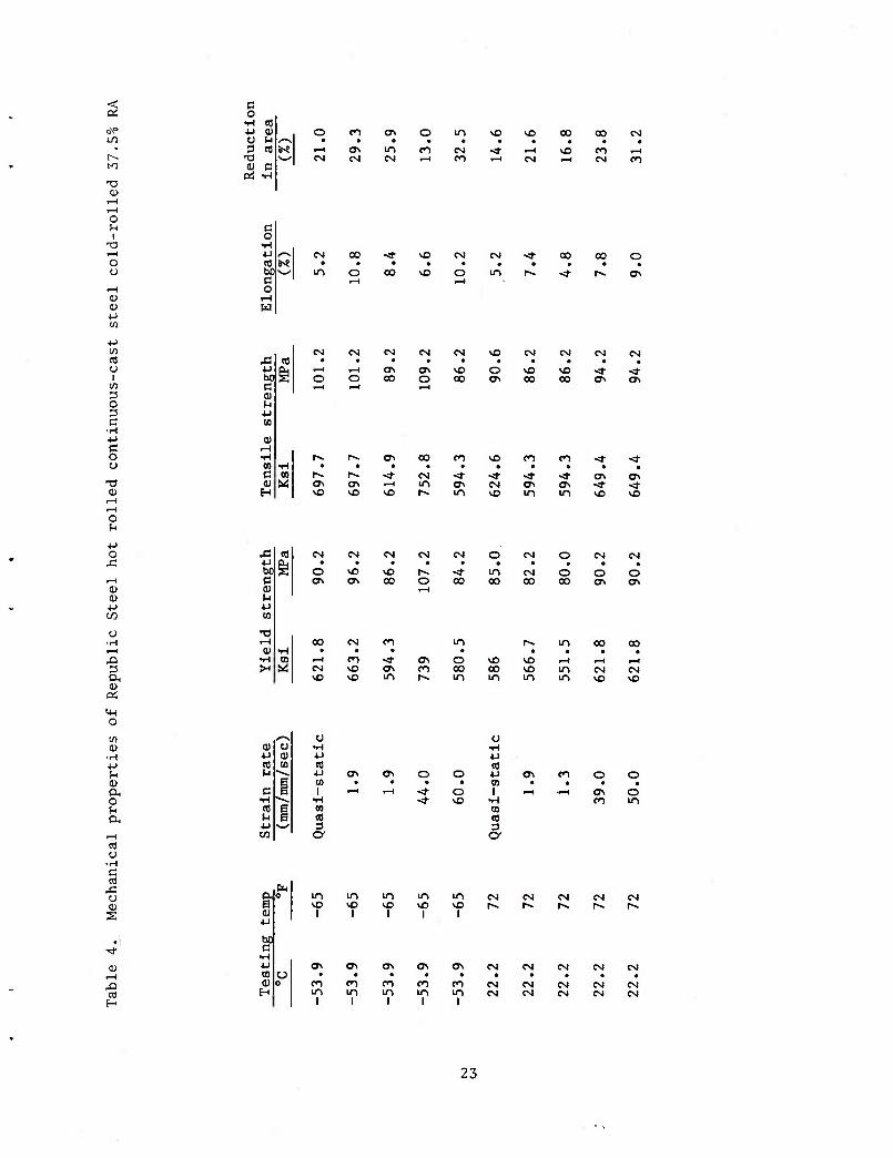
4 Mechanical properties of Republic Steel hot rolled continuous-cast steel cold-rolled 37.5% RA 23
5 Plane strain fracture toughness of Republic Steel hot rolled continuous-cast cold-rolled 37.5% RA 24
6 Plane strain fracture toughness of Ingot-cast steel cold-rolled 37.5% RA 25
FIGURES
Page
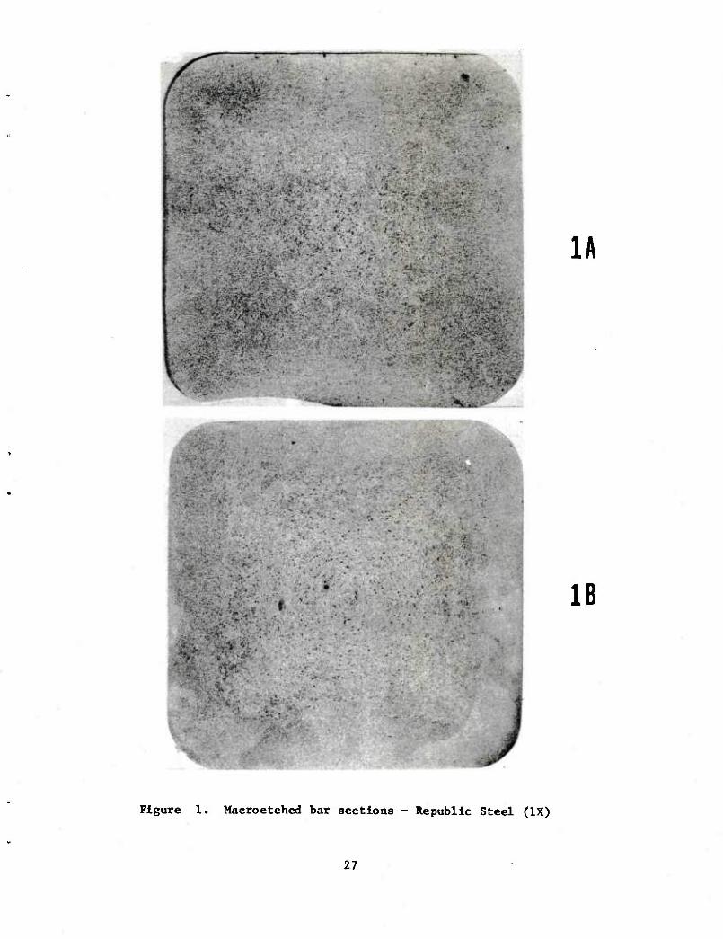
1 Macroetched bar sections - Republic Steel (IX) 27
2 Microporosity at center of bar section 1A - Republic Steel (100X) 29
3 Microporosity midway between center and edge of bar section 1A - Republic Steel (100X) 29
4 Microporosity at edge of bar section 1A - Republic Steel (100X) 30
5 Microstructure at center of bar section 1A, picral etch - Republic Steel (100X) 30
6 Microstructure midway between center and edge of bar section 1A, picral etch - Republic Steel (100X) 31
7 Microstructure at edge of bar section 1A, picral etch - Republic Steel (100X) 31
8 As-forged cavity, after shotblasting, of projectile made from Republic Steel product 32
9 Example 1 of cold-drawn process piece showing breakout at open end - Republic Steel 33
10 Example 2 of cold drawn process piece showing breakout at open end - Republic Steel 34
11 Example 1 of nosing defect (fold), internal view - Republic Steel 35
12 Example 1 of nosing defect (fold), external view - Republic Steel 36
13 Example 2 of nosing defect (fold), internal view - Republic Steel 37
14 Example 2 of nosing defect (fold), external view - Republic Steel 38
15 Example 1 of macroetched base section of projectile made from Republic Steel product 39
16 Example 2 of macroetched base section of projectile made from Republic Steel product 40
17 Microstructure of magnetic particle indication of nosing defect, picral etch - Republic Steel (100X) 41
18 Microstructure of magnetic particle indication of band seat area, picral etch - Republic Steel (100X) 41
19 Lap-type defect revealed by magnetic particle testing, picral etch - Republic Steel (100X) 42
20 Remnant of seam revealed by magnetic particle testing, picral etch - Republic Steel (100X and 500X) 43
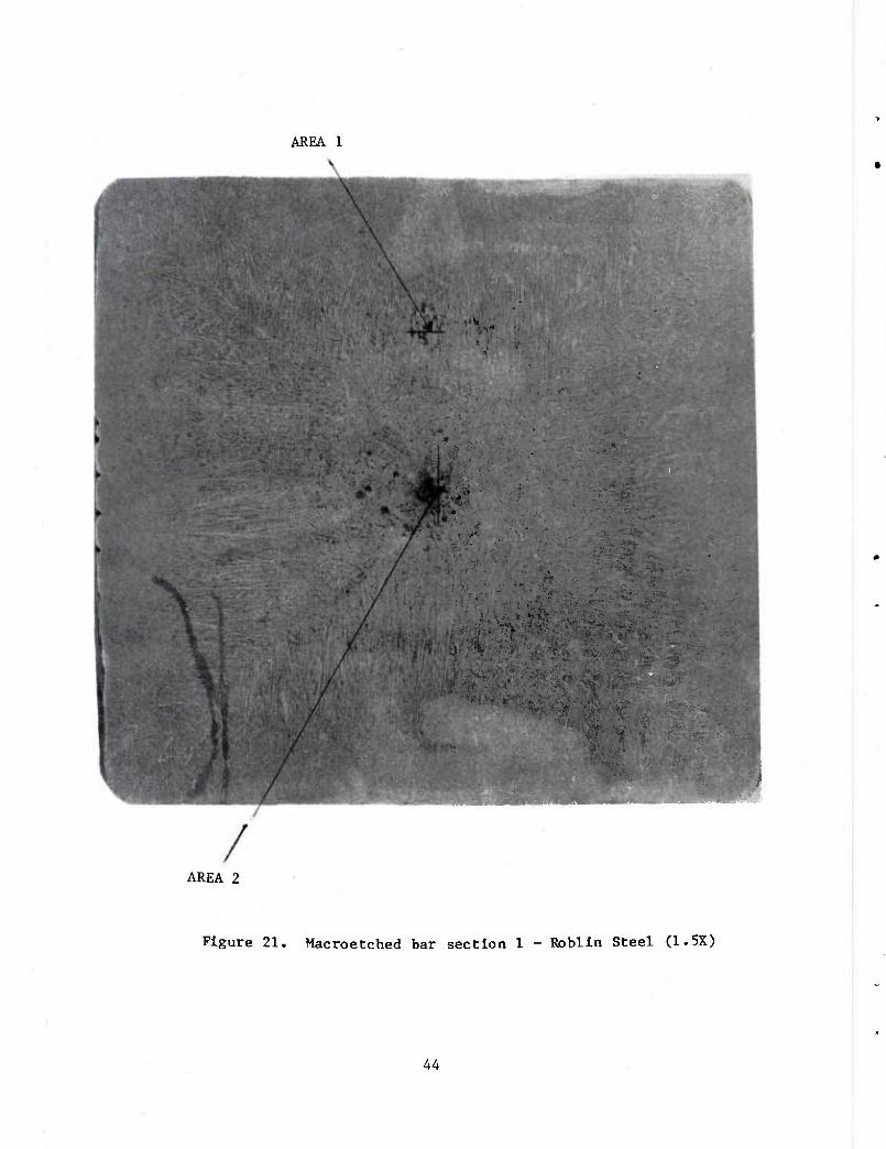
21 Macroetched bar section 1 - Roblin Steel (1.5X) 44
22 Porosity evident in area 1 of macroetched bar section 1 - Roblin Steel (100X) 45
23 Microstructure in area 2 (center) of macroetched bar section 1, picral etch - Roblin Steel (100X) 45
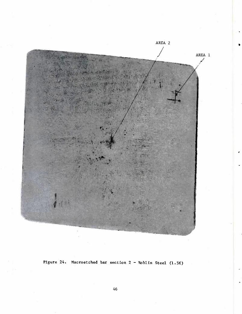
24 Macroetched bar section 2 - Roblin Steel (1.5X) 46
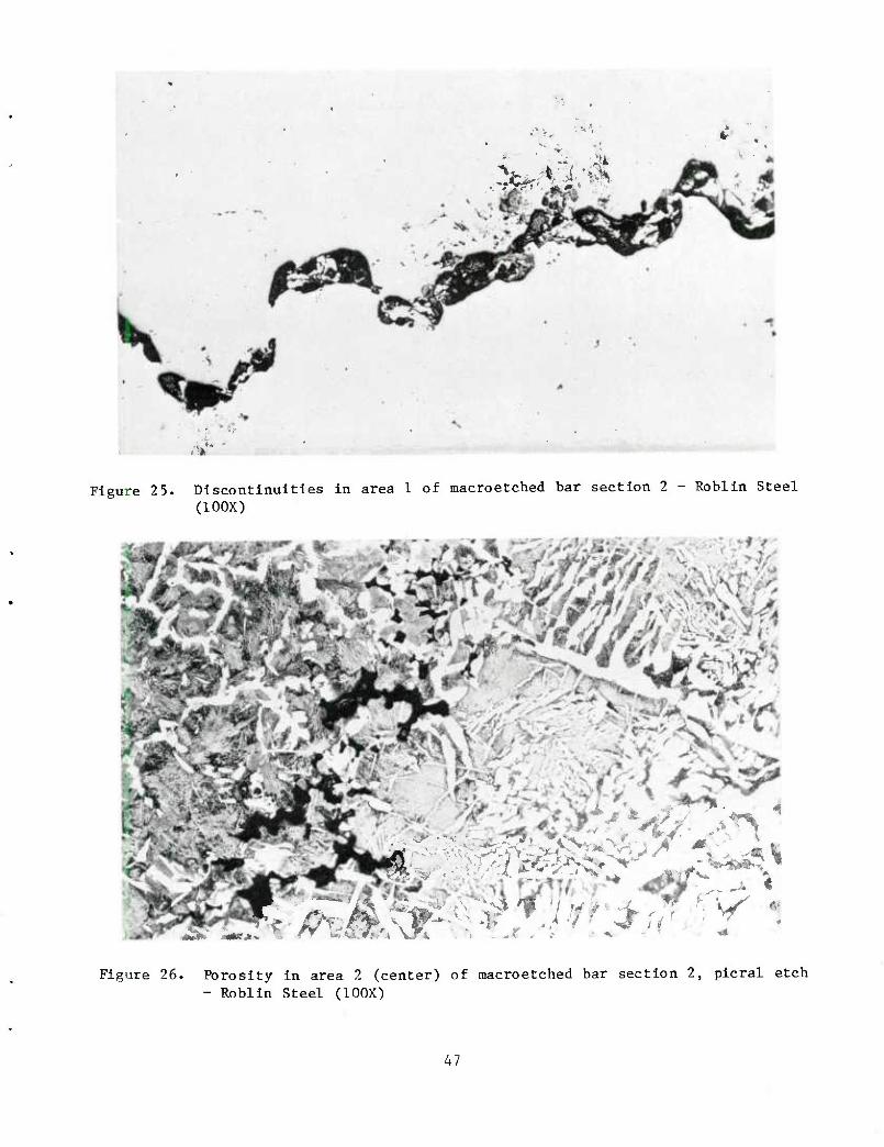
25 Discontinuities in area 1 of macroetched bar section 2 - Roblin Steel (100X) 47
26 Porosity in area 2 (center) of macroetched bar section 2, picral etch - Roblin Steel (100X) 47
27 Defective forging made from Roblin Steel product 48
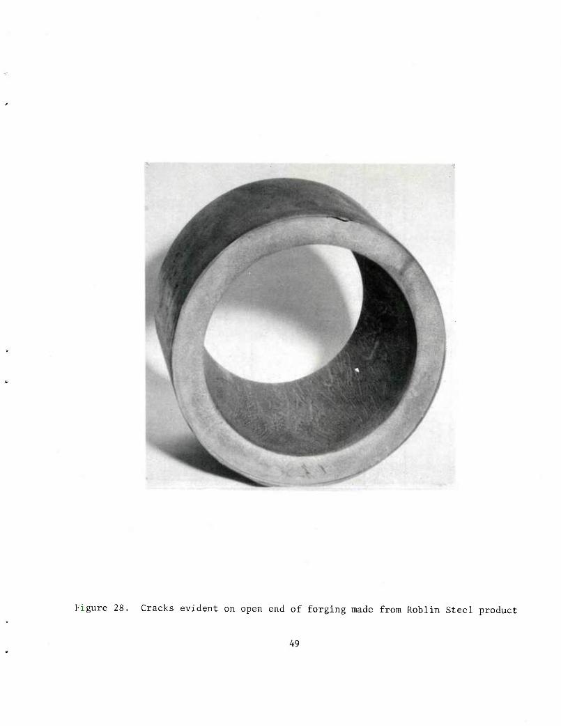
28 Cracks evident on open end of forging made from Roblin Steel product 49
29 Cracks and divergent dendritic flow lines on forging made from Roblin Steel product 50
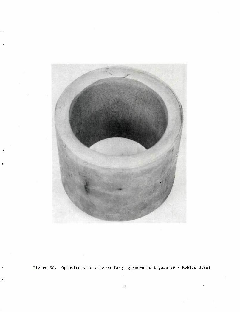
30 Opposite side view on forging shown in figure 29 - Roblin Steel 51
31 Blisters on cavity surface of forging made from Roblin Steel product (0.5X) 52
32 Cross-section of blister on cavity of forging made from Roblin Steel product (3X and 30X) 53
33 Macroetched section of forging made from Roblin Steel product 54
34 Nosing defect in projectile made from Roblin Steel product 55
35 Macroetched base of projectile made from Roblin Steel product 55
36 Mlcrosegregation in Roblin Steel product, picral etch (100X) 55
37 Dendritic porosity in base of projectile made from Roblin Steel product, picral etch (100X) 57
INTRODUCTION
One of the few recent innovations in the steel industry has been the contin- uous casting of steel. Other metals such as aluminum and copper alloys are rou- tinely continuously cast. However, steel (with its higher melting point, longer solidification ranges, and lower heat transfer rates) has presented problems which have been only recently overcome.
The advantages of the continuous-casting process are that it eliminates casting into ingots, reheating of ingots, and primary rolling of ingots into blooms. Thus, continuous-casting allows the direct casting of an intermediate product from molten steel, resulting in substantial savings in energy and in facility and manufacturing costs.
The first successful application of continuous-casting of steel was the casting of slabs for rolling into sheet and plate products. The slabs presented a large surface area for cooling, and the high reduction in area when the plates were rolled into sheet or plate compensated for lower density centers.
Once the technology had been established for slabs, it was subsequently applied to billets. However, the first billet casters made a lower quality prod- uct which was comparable to merchant-quality steel or structural steel. This technology has advanced to the point where a forging quality product and, in some instances, a higher quality product can be made on a billet caster.
The purpose of this project was to determine whether or not there are any unique characteristics of a continuous-cast product which would make it unsuit- able for ammunition manufacture. National Presto Industries, Inc., was selected to fabricate 105-mm Ml projectiles from continuous-cast steel for two primary reasons: The size of the raw material used in their process was within the range available from continuous casters and allowed for subsequent hot rolling after casting. Also, the hot cup-cold draw process used by National Presto allowed evaluation of both hot forging and cold working operations.
As early as 1968 National Presto was approached by a small continuous-cast-steel producer to fabricate some 105-mm Ml projectiles from the small producer's product. National Presto made a small quantity of projectiles and shipped them to Frankford Arsenal for examination. Although National Presto reported no problems in forming the projectile bodies, the quality of the contin- uous-cast billets used was not as good as forging-quality billet. Therefore, National Presto was informed that a more extensive program would be required to arrive at a specification which would assure a consistently high quality product.
In 1972, at the request of representatives of Republic Steel Corp., National Presto made some projectiles on a trial basis. At this time an MMT project request had been submitted concerning an investigation of continuous-cast steel. The original scope of this project was to process projectiles made from steel produced by three different steel suppliers. Funding for the project was received in Fiscal Year 1974. At that time the steel industry was being taxed to capacity, and, although National Presto contacted approximately 14 continuous- cast steel suppliers in this country and Canada, no positive response was re- ceived. Later Roblin Steel Company supplied some unworked continuous-cast steel
^P'JVT3' I975' RePublic Steel fl^lly agreed to supply AIST 1018 steel
This report summarizes the contractor's final report (ref 1) but is nWm.r i y concerned with a metallurgical examination of th. Z material IraZZ Pieces, and finished projectile bodies from the two sZr^ oT^LZl-Zl
ENGINEERING STUDY
Republic Steel Continuous-Casting Process
duly stM„d topothe with thf Ir :„rrarOUnd
ft\e Perl,,hery 0f th<! "^ ^
taSiS!rvh:„\d
p:srn1rt;sis"^ra
tn
1d
car.1"efclca"on proceeto"a m""—
tlon, water is sprayed on the outside of the billets. a"el"«e .olldlflca-
ate u^r^'"'^^ Wt^ aPPr0Xl(Mtely n7'C (l7m'F)- "-" ™""=
are allowed to ceol. .T^.L'^^^^U^^. Mllet8
dow„ s srr (3!^n„^--£;; ^'s.rnLr1^^^^""« »tely ao 85% reduetion in eross-seetional area «chU,l0g appro*!-
Processing Republic Steel Product into Projectile Bodies
A contract was placed with National Presto to process approximately 1000 105-mm Ml projectiles from AISI 1018 continuous-cast steel supplied by Republic Steel. The projectile bodies were manufactured by the same process as is used for the conventional material made from ingots (ref 1). To provide background information in support of the metallurgical study, behavior of the continuous- cast steel at each operation in the production process is presented briefly:
Receive Steel
For their normal production. National Presto orders AISI 1018 steel fully killed, nonaging, and made to fine-grain practice, (an aluminum-killed product). It further specifies a 0.10% maximum on silicon to facilitate cold working of the material. National Presto orders 89 mm (3.5 in.) round cornered, square bar steel with a 12.7 mm (0.5 in.) corner radius and a diagonal measure- ment of 115.2 mm (4.536 in.).
The continuous-cast steel supplied by Republic Steel had a ladle analysis of 0.15% silicon, which was over the maximum allowed. The explanation by Republic Steel for the high silicon content was that they cannot fully alumi- num-kill the steel on the continuous caster due to the formation of aluminum oxides during casting. Sufficient aluminum is added to the mold to refine the grain, but most of the deoxidation is achieved with silicon.
The bars also were generally oversize by 1.59 mm (0.06 in.) and varied in cross-sectional dimensions. To correct this condition, the mults had to be cut shorter.
Saw Mults
Saw blade usage was equivalent to that for ingot-cast steel, as was sawing time.
Heating for Forging
Because of the larger cross-section of the continuous-cast steel, the operating temperature of the induction heaters had to be increased 55.50C (100oF) to bring the continuous-cast steel up to the normal forging temperature of 1065oC (1950oF).
Forge
Forging tonnage was measured at the cabbage operation and was de- termined to be 22.5% higher, or 306 Mg (337 tons) for continuous-cast steel ver- sus 249 Mg (275 tons) for Ingot-cast steel. National Presto personnel reason that this Increase in tonnage was due to the shorter mult. Another contributing factor could be the coarse dendritic structure of the continuous-cast steel as compared to steel rolled from ingot. Tool life might be somewhat better for the continuous-cast steel because of a cleaner reaction with the workplece.
Rough-Turn
Maintaining weight at the rough-turn operation was a problem be- cause of cross-sectional variations in the bars. Tool life was not as good with the continuous-cast steel as with ingot-cast steel.
Cold Draw
Cold draw tonnage for continuous-cast steel was equivalent to that for ingot-cast steel. A higher Incidence of breakage at the open end of the drawn piece occurred with the continuous-cast steel. This operation is a very severe forming operation since the back end of the punch is tapered to form the thread flat. The higher silicon content and the coarse dendritic structure of the steel are the probable causes of this higher incidence of breakage.
Trim-to-Length
Tool life was shorter at this operation due to tool breakage be- cause of the broken edges resulting from the cold-draw operation. Many pieces which were broken during cold draw were cleaned up during the trim-to-length operation.
Coin
Coining was satisfactory. However, the tool had to be set ahead by 0.51 mm (0.02 in.) because the continuous-cast steel had greater sprlngback than did the ingot-cast steel.
Form Nose
A greater number of projectile bodies developed folds during the nosing operation. In many Instances this problem was due to the fact that the piece did not clean up during the trim-to-length operation. As with the coining operation, tooling had to be advanced by 0.51 mm (0.02 in.).
Stress-Relieve
Stress-relief experiments with the continuous-cast steel proiectlle bodies Indicated a higher stress relief temperature was required than with Na- tional Presto's normal steel. Their steel Is stress-relieved at 426.60C (800° F), whereas temperature of 5240C (9750F) was required to develop suitable me- chanical properties in the projectile bodies made from continuous-cast steel.
This higher temperature exceeded National Presto's furnace capa- bilities, and the contract was amended to allow the projectile bodies to be heat- treated by a commercial heat-treater. A wide spread In hardness resulted, indi- cating inadequate control by the heat-treater. Hardness ranged from 4.0 to 5.3 mm Brlnnel diameter, with 4.1 to 4.3 mm being an acceptable range. A total of 93% of the stress-relieved projectile bodies fell within the acceptable range. Subsequent heat-treating experiments on projectile bodies of 4.0 mm hardness indicated that after a 5240C (9750F) stress relief at Frankford Arsenal, ac- ceptable mechanical properties were achieved.
Finish-Machine
All finish-machine operations were Identical to those for ingot- cast steel.
Magnetic-Particle Inspect
Normal production of 105-mm Ml projectile bodies does not include magnetic-particle inspection. This inspection was made a requirement in this project to Insure that no defects peculiar to the processing of continuous-cast steel developed. No magnetic particle standards existed, so any magnetic par- ticle Indication was considered a reject. Approximately 10% of those projectile bodies inspected had magnetic-particle indications. Representative indications were raetallurglcally examined and results are discussed later in this report.
Metallurgical Study of Republic Steel Product
Raw Material
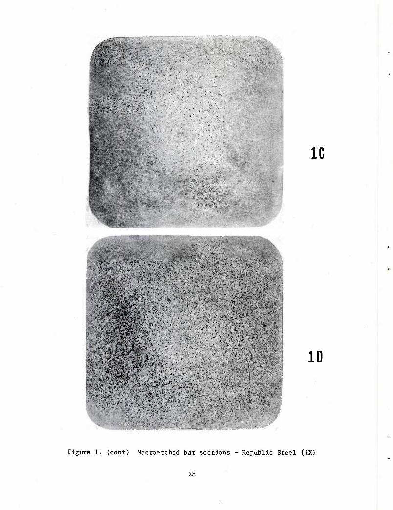
supplied steel^Vht^ 1^1^ r^lL'Z ^T *" 0f the Re^bllc- or better than the n«croetch sSnLrHc f macrographs are generally equal to
cast steel. So4 deTdAtlc s^^^^ ^ ^ ^ in^- section*- lw«»„— .u.. . UCture ^ evident in the center of the macroPtrW sections; however this si-rn^i,™ 7 " CVLUe,1L "• cne center of the macroetche
Aside f^ this dend tic ""ure n't?!/1..80 ^^ in ^t-cast steel
soundness also appears excellent To' evide^e Xtf"^^^^"vV ""T feet which is common to continuous-cast steel and wM.hn/"01^' a de~ cation. However view 1A flJ^Z i u occurs during solidifi- Generally. the surface flnishff 1' sh^ evidence of surface conditioning, steel rolled from ingot. continuous-cast steel is superior to that of
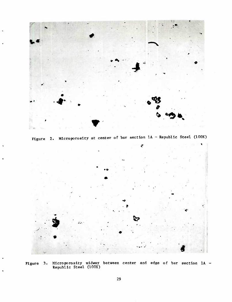
The macrospeclmen shown in view 1A f-ftmrp I t7=,o ^ u up for metallurgical examination. MetalWraoM'/;^ ' subsequently cut the edge, midsection, and center of "I*: ? p Speclraens were prepared from are shown in figures 2 throueh 4 r^ <7 IT^^' Unetched microstructures center of the tar! T^s^oLoJ^^^ mlcroPoros^y is evident in the tween the center and ed.e mi
:,C;OP°rOSlty di^n^hes somewhat at the midpoint be-
the edge. T^is Tcropofo'sUv do^ n't ^ '' ^ ^^^ disappears at with it and will Clos^r^ eclated
shown in figuresc^e^^r^ugr7:^^e^eTyns d
Tehpeicted in figures 2 thro^h * -
very uniform from center to IAI* ^u *' microstructure is shown to be
be apparent InTn ^W ^^inu^utcTst^r^ur^ ^7^°" ^ ^ similar to that expected In bars rolled from Ingot-cast'steel ^^ 1S ****
bar, a chemical anal^ls^was'maT o'/^ f^^"- exi^s in a continuous-cast
ter of the macrospeclmen sZ^l view' IA ^L^e l" MM I56.3"' " ^ Cen- of these analyses to be very close wit-h cH JT 1 le 1 ShOWS the results
cross-section of the lMot 1^ fZW- I ."'* """'i"'"l ""!• the large
aower at the ed(!e ^ ZZ t^J^^^TL™^'"1™?"1' l
perature and rolling to finished elr* hd ne fenter. Heating to rolling tern-
hot a sedated l^^Ys l^lZAt llltZt T^IZ ~C'
^TsZizii:^1 has the ad"— ^ »■>" souamc1:^:: rc^0^
Forging
Aside from the increased tonnage required in the hot forging opera- tion, little .difference was distinguished between the two steels. A portion of the cavity surface, which is excellent, is shown in figure 8. Also evident is a slight amount of earing at the open end of the forging which is normal for ingot- cast steel. No unusual defects resulted from the forging operation, and the extent of rework such as removing seams and tool marks was the same as with ingot-cast steel.
Cold Draw Operation
Representative examples of chipping or breaking of the rim in the cold draw piece are shown in figures 9 and 10. A cross section of a cold drawn piece is shown in figure 9; also shown is the degree of taper formed between the punch and die at the open end. A tendency for pinching of the metal at the open end results in occasional breakage. Many of these defects were machined off during trim-to-length; however, the irregular surfaces shown in figures 9 and 10 produced the excessive tool breakage during the trimming operation. The process piece shown in figure 9 probably could not be salvaged; however, the process piece shown in figure 10 could be salvaged. Some projectile bodies which did not cleanup during trim were nosed, which usually led to the condition discussed below.
Nosing
oom The nosing operation performed at National Presto is done at ru^ temperature without benefit of any stress-relief after cold draw. The taper put on the open end of the cold-drawn piece severely cold works the steel in this area. The nosing operation is different from most forming operations In that the steel is gathered or thickened. For this thickening to occur, uniform metal flow is required. A nick or chip on the open end of the process piece will interrupt the metal flow and will result in a fold during the nosing operation.
Two views each of two separate projectile bodies with nosing de- fects are shown in figures 11 through 14. The projectile body shown in figures 11 and 12 has sheared through the wall during nosing, displacing steel to the inside and producing cracks farther down the nose. These cracks are more evident in figure 12.
The projectile body shown in figures 13 and 14 folded inward during nosing, also displacing steel to the inside, which is more evident in figure 13. This defect does occur in regular production with ingot-cast steel and is not believed to be in any way associated with the material properties of continu- ous-cast steel. Projectile bodies with defects like those depicted in figures 11 through 14 cannot be salvaged. However, some projectile bodies with less severe defects were salvaged.
Macroetched specimens of base sections of two projectile bodies are
t^tui andThe15 ff ^ ""^ eVldenCe eXiStS 0f -Jants of ^e^ iS rHlnfr^'K KI , sPecl"ien appears comparable to ingot-cast steel. Segregation
in o !" .trr' ^"^ ^^ iS ^^^^ t0 0r te«« «- ^- occ^rrTrin ingot-cast steel
Magnetic-Particle Indications
^ff< ^ • ^ prl"clPle disadvantage of magnetic-particle inspection is the difficulty in determining depth or severity from a surface indication ThlZ projectile bodies had already passed through inspection station 4-fat Nationa Presto whxch requires a 100% visual inspection, and had been accepted. Repre-
r:^LV%rVrrntk1foerd A'1" Tr ""^"^"Ide indications were'selected^
returned to Frankford Arsenal for metallurgical evaluation. Of all the proiec- lle bodies examined, only one appeared to have a crack, which occurred in the
aose of the projectile body (figure 17). This crack is the remnant of a fold
s'L the'fr T^ WhlCh did n0t Clean UP dUring the — b0^ operation Since the flow lines are perpendicular to the surface on the right of the crack the indication is that a folding action has occurred. '
Jypical reniaining projectile bodies having magnetic particle indi- cations are shown in figures 18 through 20. The defect ^hown in figure 18 occur-
Thls- dlf ^ e band "^ and eXtendS 0-25 -" (0-010 ln-) telJ the surface, operation ThaePPdeafr%t0V. be.a,.lap Which would — during the cold dra" operation. The defect shown in figure 19 is another lap of lesser magnitude.
bar stock wJ^ ^^^ ^ ^ A' f±RUre 20' iS the remnant of a se^ ^ the cup Sonie tr WaS/ ^^Pletely removed during machining of the hot forged cup Some iron oxide scale, associated with the defect, is evidenced In the higher magnification photograph in view B. figure 20. All of the defects indi- cated by ^gnetic-particle inspection, with the exception of the nose crack would no interfere with the safe functioning of the projectile because of thei; orientation and shallow depth. The nose crack, however, is severe enough t^ warrant rejection of the projectile. severe enough to
Mechanical Properties of Republic Steel Projectile Body
ment at 524^ « ?^ f ^O^ SUbjeCted t0 a second stress-relief heat treat- ies ReluU. ll\l minUteS ^ WaS then C"ted for "-echanical proper- ertl' re!uU of the TorH'T"16^8 ^ ^^ in ^ 2' The -chanical prop- erty results of the low hardness projectile body are below the minimum yield
elon^M rTiremeiVor ^ Ml [448.2 MPa (65,000 psi)]. However, the percent elongation far exceeds the 15% minimum requirement for the Ml. Conversely the
high-hardness projectile body does not meet the minimum elongation requirement in the nose and is at the minimum in the band seat. (The base results are provided for information only since the Ml is not normally tested in the base and trans- verse ductility is not a requirement.) The projectile body within the accept- able-hardness range meets all of the requirements, as does the high-hardness projectile body which was re-stress relieved. This points out the fact that the projectiles were subjected to a nonuniform heat-treatment by the commercial heat- treater.
Roblin Steel Unworked Continuous-Casting Process
Roblin Steel supplied only enough steel to make five forgings and five pro- jectile bodies. Roblin Steel produces approximtely 108 Gg (120,000 tons) of carbon and alloy steel per year in the form of bar and rod sections up to 38.1 mm (1.5 in.) in diameter. Their steel is rolled from 101.6 mm (4 in.) square con- tinuous-cast billets. Hot metal is produced in two 27.2 Mg (30 ton) direct-arc furnaces which use a 100% scrap charge. Two strands are cast simultaneously, are allowed to solidify in the vertical position, are then bent to the horizontal position, and are parted by flame cutting. The only other forging application of unworked continuous-cast steel known by Roblin Steel is for the production of high-performance forged crankshafts produced by General Motors.
Only a small amount of steel was processed because National Presto could not accommodate the 101.6 mm (4 in.) square cross-section. Forge tooling and billet heaters are sized for 88.9 mm (3.5 in.) round cornered square bar steel with quite precise diagonal dimensions. For the process pieces that were run, the billets were machined to 88.9 mm (3.5 in.) square steel.
Metallurgical Study of Roblin Steel Product
Raw Material
A macrograph of an unworked continuous-cast steel billet typical of the quality Roblin Steel produces is shown in figure 21. A coarse dendritic structure is evident; however, the soundness appears to be good. Areas 1 and 2 of figure 21 were selected for microscopic examination. Stains evident on the macrograph in area 1 indicated a small amount of porosity as shown in the unetched micrograph in figure 22. Area 2 represents the very center of the un- worked continuous-cast steel billet and, from the macrograph, could have been interpreted as showing porosity. However, the micrograph of area 2 in figure 23 shows no porosity. The structure shows wiedraanstatten ferrite (white phase) and very fine pearlite (dark phase) which is indicative of an unworked continuous- cast steel structure. What appeared to have been porosity was an area of segre- gation which was attacked by the macroetch.
Another similar section typical of the quality Roblin Steel pro- duces is shown in figure 24, with areas of specific interest indicated. Area 1
of figure 24 shows a stain which indicates a separation adjacent to a dendrite. This separation occurs when the volume of liquid metal between dendrites Is not sufficient to fill the space upon solidification. Another cause is deformation of the unworked continuous-cast steel billet while liquid metal is remaining between dendrites. This deformation is caused by twisting of the billet while it is being extracted from the mold and by bending of the billet from a vertical position to a horizontal position. This condition is shown in figure 25 and is distinguished from a crack by its being a series of connected and disconnected voids. This type of defect will heal itself with subsequent hot working, because normally no oxides are associated with the voids. The center of the billet (fig. 26) also shows interdendritic porosity. The difference in microstructure on either side of the porous area is due to alloy segregation, with the alloy pro- bably being manganese.
Process Pieces
The unworked continuous-cast steel appeared to have less ductility in hot forging than the conventional AISI 1018 material. A forging made from the unworked continuous-cast steel, with a large crack starting at the open end is shown in figure 27. Such defects occur occasionally with ingot steel, but the defects in those instances are due to seams in the surface of the bar. Unworked continuous-cast steel has excellent surface finish and, since this steel has not been rolled, the presence of seams is unlikely.
Several mm of the open end of two other forgings were removed and macroetched (figures 28 and 29). Small cracks are evident on the face of the open end of the forging, and a coarse dentritic structure is also evident. Another view of the crack in figure 29 (fig. 30) shows small defects 180° apart. The defects occur at locations where the flow lines diverge; thus the coarse dendritic structure results in greater directionality of properties, which would be a problem under production conditions. Microscopic examination of these small cracks did not shed any more light on their cause and did not show any massive inclusions which could have caused Initiation of these cracks.
Another condition evident in forgings made from unworked continu- ous-cast steel is the formation of blisters on the cavity surface as shown in *lgure it' Cross-sections of a blister at higher magnifications are shown in tlgure 32. Again, no evidence in the raicrostructure indicates what would cause the defect A probable cause is that gas is trapped in voids near the center of the unworked continuous-cast steel billet. During forging, the voids are dis- tributed next to the punch on the cavity surface. Expansion of the entrapped gas at the forging temperature causes the blisters once the support of the hot foree punch is removed.
The macroetched structure of a forging is shown in figure 33. The dendritic structure is still evident in the base area and along the cavity sur- face. The dark spots are areas of alloy segregation rather than voids.
10
A defect occurring in projectile bodies made from unworked contin- uous-cast steel occurring during the nosing operation and similar to those de- fects experienced with the Republic Steel products is shown in figure 34, Cracks similar to those shown in figures 28 and 29 could also cause this defect if not completely removed prior to cold draw and nosing.
The macroetched base section of a projectile body is shown in fig- ure 35 and the dendritic structure is still evident. Some segregation is also evident. The manner in which alloy segregation affects the microstructure is shown In figure 36. The darker area in the center of the photograph has a higher percentage of pearlite, which is due to a higher concentration of manganese. Unworked continuous-cast steels are more prone to exhibit segregation because they have not been worked and reheated as has the Republic Steel continuous-cast product.
Some scattered porosity was also evident in the base of the projec- tile body, as indicated in figure 37. This defect appears to be dendritic poros- ity which did not close during forging since the base does not undergo as much deformation as the sidewalls. A comparison of the microstructure in figure 37 with the microstructure in figures 22, 23, 25 and 26 shows the degree of refine- ment obtained by reheating for forging.
Mechanical Properties of Roblin Steel Projectile Body
One of the nosed projectile bodies was stress-relieved at 4820C (900oF) for 1 hour and was subjected to mechanical property testing. Two tensile specimens were removed from the rotating band area 180° apart, and one specimen- was removed from the base, 25.4 ram (1 in.) from the center line. All of the specimens comply with the minimum requirements for the Ml projectile of 448,1 MPa (65,000 psi) yield strength and 15% elongation. These properties compare favor-, ably with the properties of 105-ram Ml projectiles made from ingot-cast steel, as is shown in table 3.
Ballistic Testing
A quantity of 100 projectiles made from the Republic Steel hot rolled con- tinuous-cast product were ballistically tested at Jefferson Proving Ground,
A total of 50 projectiles were fired for a first-article-sample test as specified in MIL-P-60547C (the item specification for the 105-mm Ml projectile). This test requires the firing of 30 rounds at ambient temperature and at excess pressure and 20 rounds at ambient temperature and at service pres- sure. These projectiles were recovered and measured after firing. Deformation greater than 0.025 mm (0.010 in.) on either the body diameter or bourrelet di- ameter was cause for failing the test. Loss or breakup of metal parts was also cause for failing.
11
The remaining 50 projectiles were fired at -53 90C f-6S0in -^ .
(ref 2). results of all rounds were acceptable
Fracture Toughness Test
The plane strain fracture toughness of the Republic Steel hot rn^^0l^ uous-cast product was dptPrmino^ *r,A c^uuxic sceei not rolled contin-
steel In service. relation between failure stress and defect size for a
Test Procedure
fracture l^Ts TL ^ctS ^^ITn^ 7°^ ^ ^ ^^ a
test. Billet ends were norn^lized at s'i'-C J^O^0 . ^ ^ USed f0r this 37.5% reduction in area. This steel L!^ ) ^ Were cold-rolled to a for 1 hour. Standard tensne Zr\ ^ress-relieved at 398.9°C (750°F) direction and were ^^^T^^ —erse rates. Compact fracture toughness sDeMmVnc * • ( F) at varying strain were machined from the cold-roll!d M n ^ T COnforinin^ t0 AS™ Standard E399 the specimen was in the W tr^, .S " f" orlentation where the width of the longitudinal axis rl trafverse direction and the notch was parallel to Standard E399 ^ SPecimens — then tested in accordance with Asm
Test Results
rates ^'^M^^L^. ^.Zt^TVl ~ ^
-53.90C (-65°F). The yield ^rlncr^. l0Wer at roora temperature than at projectiles (table 2) Xth L e'ZL^r^r^^ t0 reSUltS 0btained fr™ specimens is lower due ^S^Jn^eZt^ ^^ ^^ ^ ^ Ensile
rates andR\%" JtLe^Tor SttSt\orCrtoUirie H^^r35 teSting at ^ous strain table 5 A Consistent ^^0^ bXet ZlTZ^ T\ ^ ^T ^ values does not exist. However a r^l^T \- 7 nd fracture toughness Perature and fracture 'oJ^'iZZT^J!°V^Z££Z ^ ^
12
-53.90C (-65°?)]. Fracture toughness at room temperature is higher for the hot rolled continuous-cast steel then for the Ingot-cast steel (table 6). This Increased room temperature toughness may be due to a lower fracture toughness transition temperature in the hot rolled continuous-cast steel. The fracture toughness of hot rolled continuous-cast steel in general compares favorably with that of the ingot-cast steel.
Specification Requirements
Based on experience with the Republic Steel hot rolled continuous-cast pro- duct, the macroetched standards should be the same as those implied for special quality bar and semi-finished forging quality billet, depending on product size required. Unworked continuous-cast steel will not meet these requirements.
Chemistry requirements of continuous-cast steel should remain the same as ingot-cast steel with the realization that if a fully aluminum-killed steel is required, the source of supply may be limited.
Since current material specifications (ASTM or Military) do not specifically limit the use of continuous-cast steel, no supplement to these specifications is required.
To allow the use of a continuous-cast steel for manufacture of projectile bodies an additional requirement should be added to the drawing as follows: "Continuous-cast steel shall be permittted provided that, subsequent to casting, the steel shall be hot rolled to a minimum of 75% (4:1) reduction in cross- sectional area.
CONCLUSIONS
Hot Rolled Continuous-Cast Steel
1. To produce a continuous-cast steel with quality equivalent to an in- got-cast steel, a reduction in cross-sectional area of at least 4:1 after casting is required.
2. Hot rolled continuous-cast steel is suitable for manufacture of pro- jectile bodies by either the hot cup-cold draw process or by the hot-forge-and- machine process.
3. Base soundness (lack of porosity) of projectile bodies made from hot rolled continuous-cast steel is acceptable and is comparable to that of bodies made from ingot-cast steel.
13
4. Plane strain fracture toughness of hot rolled continuous-cast steel is equivalent to that of ingot-cast steel.
stee! rll h 1° ^^ mechanical Pr°P"ties comparable to those of ingot-cast
ature than 1./ . COntlnuOU,S CaSt steel ^^^ higher stress-relief temper- acure than does ingot-cast steel.
6. Hot rolled continuous-cast steel is less ductile in cold drawing and nosing operations than is the ingot-cast steel. rawing and
w^h J/i ^ 'h%n,anufacture of Projectile bodies, a higher reject rate occurred with bodies made from hot rolled continuous-cast steel than occurred with bodies made from ingot-cast steel. However, this reject rate could be reduJd if toJl- steelT.d processing were optimized (such as has been done for the ingot-cast
Unworked Continuous-Cast Steel
1. Unworked continuous-cast steel is not snii-aMo f^r- ~ * Projectile bodies by either the hot cup-cold^dra^ proc^s^or^by Th"0^ and-machine process because of its low ductility, its poor dimensional "0^^ and the presence of blisters on the cavity surface. dimensional control,
cast stee'l. "^^^ ™ntinuous-cast steel is not comparable in quality to ingot-
3. Unworked continuous-cast steel is less ductile in cold drawing and nosing operations than is hot rolled continuous-cast steel. drawing and
4. Some evidence of base unsoundness (presence of porosity) appeared In projectile bodies made from unworked continuous-cast steel. appeared in
14
RECOMMENDATIONS
1. Unworked continuous-cast steel should not be adopted as an acceptable steel for manufacture of projectile bodies.
2. Hot rolled continuous-cast steel should be adopted as an acceptable steel for manufacture of projectile bodies. However, this adoption should be subject to the incorporation in the TDP of the following requirement:
"Reduction by Rolling: Subsequent to casting, the continuous-cast steel shall be reduced in cross-sectional area by hot rolling until the area is 25% of its original size (that is, a 4:1 reduction)."
3. The TDP for manufacture of projectile bodies should be changed to show the acceptability of hot rolled continuous-cast steel for manufacture of projec- tile bodies, subject to the conditions in recommendation 2 above.
15

REFERENCES
1. National Presto Industries, Inc., Final Report, Contract No. DAAA25-75-C- 0614 (undated).
2. "Engineering Design Test of Projectile, 105-mm, Ml Type, Continuous Cast Steel," U. S. Array Jefferson Proving Ground, Test Report 76-703, Jefferson Proving Ground, Madison, IN, July 1976.
17
Table 1. Chemical analysis of Republic Steel continuous-cast product
Wt. (%) Check analysis Ladle analysis
Element Edge Center
Carbon 0.20; 0. 19 0.18; 0.18 0.185
Manganese 0.66 0.66 0.68
Phosphorus 0.002 0.002 0.007
Sulfur i
0.018 0.018 0.023
Silicon 0.10 0.10 0.15
Nickel 0.02 0.06 0.07
Copper 0.05 to 0 .15 .0.05 to 0.15 0.14
Chromium 0.06 0.06 0.08
19
Table 2. Mechanical properties of Republic Steel projectile bodies
c , Yield Tensile _SpeclmejL__ __strength strength Elongation (%)
Low-hardness projectile body
Ogive area MPa Ps^ MPa psi
1 302.6 43,900 415.0 60.200 37
315.7 45,800 417.1 60,500 37
Band seat area
1 336.4 48,800 441.9 64,100 33
2 290.9 42,200 437.1 63,400 32
Base area 466.1 67,600 557.8 80,900 17
High-hardness projectile body
1 692.9 100,500 768.8 111,500 13
2 683.9 99,200 763.3 110,700 14
Band seat area
1 628.8 91,200 710.9 103,100 15
2 626.7 90,900 708.8 102,800 15
Base area 601.9 87,300 677.1 98,200 8
20
Table 2 (cont)
Acceptable-hardness projectile body
Yield Tensile strength strength
Ogive area MPa psi MPa psi
1 631.6 91,600 693.6 100,600
2 597.8 86,700 670.2 97,200
High-hardness projectile body subjected to second stress-relief heat treatment*
At 5240C (9750F) for 30 minutes,
Elongation (%)
17
18
Band seat area
1 555.0 80,500 631.6 91,600 17
2 524.7 76,100 614.3 89,100 16
Ogive area
1 654.9 95,000 717.1 104,000 16
2 666.1 96,600 722.6 104,800 16
Band seat area
1 581.2 84,300 664.0 96,300 17
2 615.7 89,300 688.1 99,800 17
Base area 534.3 77,500 622.6 90,300 14
21
Table 3. Comparison of mechanical properties of projectiles of Roblin ^ i Projectile bodies with ingot-cast projectile bodiL '^
Specimen Yield strength
Tensile strength
Elonga- Reduction t^on(%) in area (%)
Unworked continuous cast steel*
nra psi MPa
657.7
psi
18 0° bourrelet 584.6 84,800 95,400 54 180° bourrelet 558.4 81,000 538.4 92,600 20 56 Base 523.9 76,000 628.7 91,200 17 53
Ingot-cast steel
0° bourrelet 634.9
180° bourrelet 630.1
Base 550#1
92,100 708.7 102,800 15 51
91,400 721.1 104,600 15 48
79,800 641.1 91,800 11 19
Stress relieved at 4820C.
22
<
o\=> •H cq 4-J (D O M y«\
3 « ^ X) S_^
OJ c Pi ■H
£N CM in CM
O
CO
U-| ^o vO 00 00
CM -a- -H vo fl •—l CO r-l CM •-H CM CO
o u I
iH o o
!T3 W) C o
e^s CM 00 -<f VD CM CM -tf 00 00 o • • • • • • • • • • LO o 00 vC o iri r- <« r** ON
+-> 10 ni O
i ui D O
c •H (J C o o
bo C
CM
1-4 t—) C^ <^ v£) O v£> VD ■<1- <r O o 00 o 00 Os 00 00 as OS
ON 00 CO VO ro n r- r-~ «# CM -* -* >* •« Os o\ CN as f-H u-l as CM as Ov st -* vO vO vO r~- m VD LO in vO VD
o
o
■I-J on
u •H t—I
o a:
o m <u
•H
pit o
a.
03 u
•H c
U o
i—i
bO C 0)
•u 03
H 0)
•H
CM CM CM CM
o SO s£> t-~ -* m CM o o o CTv OS 00 o 00 00 00 00 OS Os
00 CM CO u-i 00 00
t-H cn -* Os o VD vO —l —t ^H CM vO ON cn oo 00 VD u-l CM CM VO VD u-l r- m u^ u-l u-l vD VD
^-N
a) o ■u « cfl to M
C g •H -^N,
<fl g kl P 4J ^^ C/2
4J ON CO •
I -H •H to « &
as
o vD
4J Ov W • I **
1-<
00
(0
CO
•■—i ON CO
O u-i
S
g
u-i u-i u-l m u-i CM CM CM CM CM VD
1 VD
1 vD
1 vD
I VD
1 r^ r-^ r^ r-^ t-~
ON ON ON CN CM
cn CO c-i cn CO CM CM CM CM CM u-i
1 u-l
1 U-l
1 u->
1 u-i
1 CM CM CM CM CM
23
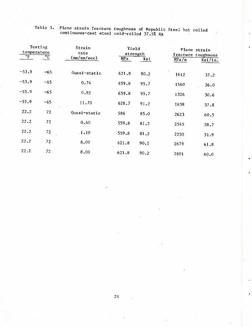
Table 5. Plane strain fracture toughness of Republic Steel hot rolled continuous-cast steel cold-rolled 37.5% RA
Test Ing Strain temperature rate 0F 0C (mm/mm/sec)
-53.9 -65 Quasi-static
-53.9 -65 0.74
-53.9 -65 0.92
-53.9 -65 11.70
22.2 72 Quasi-static
22.2 72 0.40
22.2 72 1.10
22.2 72 8.00
22.2 72 8.00
Yield strength
MPa Ksl
Plane strain fracture toughness
621.8 90.2
659.8 95.7
659.8 95.7
628.7 91.2
586 85.0
559.8 81.2
559.8 81.2
621.8 90.2
621.8 90.2
MPa/m Ksi/in.
1612 37.2
1560 36.0
1326 30.6
1639 37.8
2623 60.5
2545 58.7
2250 51.9
2679 61.8
2601 60.0
24
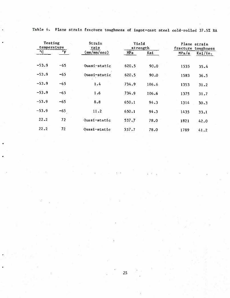
Table 6. Plane strain fracture toughness of ingot-cast steel cold-rolled 37.5% RA
Tes tempe
ting rature
"F
-65
Strain rate
(mm/mm/sec)
Quasi-static
Yield strength
Plane fracture MPa An
1535
strain toughness
0C MPa
620.5
Ksi
90.0
Ksi/in.
-53.9 35.4
-53.9 -65 Quasi-static 620.5 90.0 1583 36.5
-53.9 -65 1.4 734.9 106.6 1353 31.2
-53.9 -65 1.6 734.9 106.6 1375 31.7
-53.9 -65 8.8 650.1 94.3 1314 30.3
-53.9 -65 11.2 650.1 94.3 1435 33.1
22.2 72 Quasi-static 537.7 78.0 1821 42.0
22.2 72 Quasi-static 537.7 78.0 1789 41.2
25
1A
IB
Figure 1. Macroetched bar sections - Republic Steel (IX)
27
1C
-.. r
■ -■ ;y'-.. .•■
-#«•- .."l*
I >'■■-' ID
'■ '
Figure 1. (cont) Macroetched bar sections - Republic Steel (IX)
28
v«
4
• »
Figure 2. Microporoslty at center of bar section 1A - Republic Steel (100X)
• *
<-
^
te» '
Figure 3. Microporoslty midway between center and edge of bar section 1A Republic Steel (100X)
29
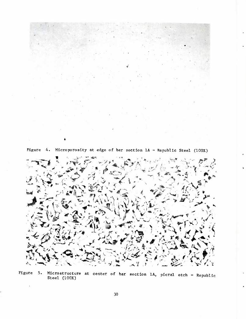
Figure 4. Microporosity at edge of bar section 1A - Republic Steel (100X)
Figure 5. Mlcrostructure at center of bar section 1A, plcral etch - RenuhUr Steel (100X) ^puoxic
30
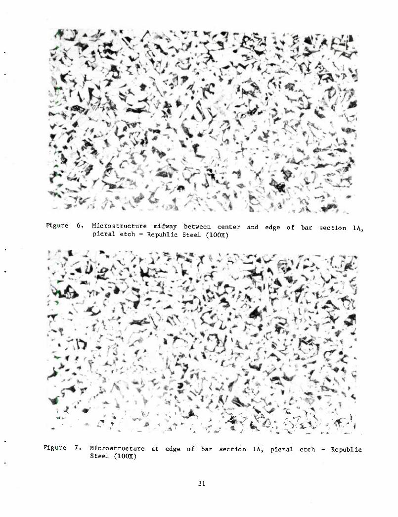
Figure 6. Micro structure midway between center and edge of bar section 1A, picral etch - Republic Steel (100X)
Figure 7. Micro structure at edge of bar section 1A, picral etch - Republic Steel (100X)
31
Figure 8. As-forged cavity, after shotblasting, of projectile made from Republic Steel product
32
Figure 9. Example 1 of cold-drawn process piece showing breakout at open end Republic Steel
33
■if'
;'
Figure 10. Example 2 of cold drawn process piece showing breakout at open end Republic Steel
34
Figure 11. Example 1 of nosing defect (fold), internal view - Republic Steel
35
Figure 12. Example 1 of nosing defect (fold), external view - Republic Steel
36
Figure 13. Example 2 of nosing defect (fold), internal view - Republic Steel
37
Figure 14. Example 2 of nosing defect (fold), external view - Republic Steel
38
/
• 3:
f&-*utiSjH[ri
m
;
Figure 15. Example 1 of macroetched base section of projectile made from Republic Steel product
39
mmmmmmmm
III r\k:- i '
"^ "• g^lL L* p^^ec,,ad ba8e Mct10" °f ^«"1« -*• ^
40
Figure 17. Microstructure of magnetic particle Indication of nosing defect,
plcral etch - Republic Steel (100X)
Figure 18. Microstructure of magnetic particle Indication of band seat area, plcral etch - Republic Steel (100X)
41
Figure 19. Lap-type defect revealed by magnetic particle testing, picral etch Republic Steel (100X)
42
A (100X)
|J (500X)
Figure 20. Remnant of seam revealed by magnetic particle testing, picral etch Republic Steel (100X and 500X)
43
AREA 1
\
AREA 2
Figure 21. Macroetched bar section 1 - Roblln Steel (1.5X)
44
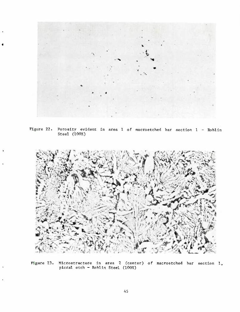
Figure 22. Porosity evident in area 1 of macroetched bar section 1 - Roblin Steel (100X)
Figure 23. Microstructure in area 2 (center) of macroetched bar section 1, picral etch - Roblin Steel (100X)
45
/
7 \ 7
■» *"*
^ ^^*
AREA 2 /
Figure 24. Macroetched bar section 2 - Roblin Steel (1.5X)
46
£
,%'" ■
Figure 25. Discontinuities in area 1 of macroetched bar section 2 - Roblin Steel (100X)
«dk tfMU
k i
Figure 26. Porosity in area 2 (center) of macroetched bar section 2, picral etch
- Roblin Steel (100X)
47
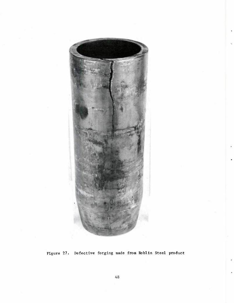
Figure 27. Defective forging made from Roblln Steel product
48
■
Figure 28. Cracks evident on open end of forging made from Roblin Steel product
49
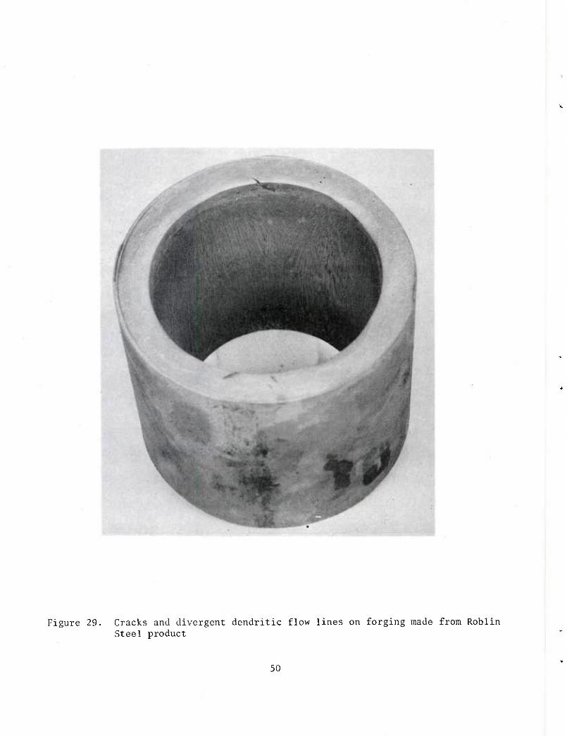
Figure 29. Cracks and divergent dendritic flow lines on forging made from Roblin Steel product
50
v
Figure 30. Opposite side view on forging shown in figure 29 - Roblin Steel
51
Figure 31. Blisters on cavity surface of forging made from Roblin Steel product (0.5X)
52
A C3X)
B (30X)
Figure 32. Cross-section of blister on cavity of forging raade from Roblin Steel product (3X and SOX)
53
Figure 33. Macroetched section of forging made from Hoblln Steel product
54
o Figure 34. Nosing defect in projectile made from Roblin Steel product
55
•;
Figure 35. Macroetched base of projectile made from Roblln Steel product
Figure 36. Mlcrosegregation in Roblin, Steel product, picral etch (100X)
56
1 ■;:r':
Figure 37. Dendritic porosity in base of projectile made from Roblin Steel product, picral etch (100X)
57
DISTRIBUTION LIST
Commander U.S. Army Armament Research and
Development Command ATTN: DRDAR-TSS (5)
DRDAR-GCL DRDAR-LCU-C (2) DRDAR-LCU-M (20) DRDAR-TSS (5)
Dover, NJ 07801
Administrator Technical Information Center ATTN: Accessions Division (12) Cameron Station Alexandria, VA 22314
Commander US Army Munitions Production Base
Modernization Agency ATTN: SARPM-PBM-MA (2) Dover, NJ 07801
Director U. S. Army Materiel Systems Analysis Activity ATTN: DRXSY-MP Aberdeen Proving Ground, MD 21005
Commander/Director Chemical Systems Laboratory U. S. Army Armament Research and
Development Command ATTN: DRDAR-CLJ-L
DRDAR-CLB-PA APG, Edgewood Area, MD 21010
Director Ballistics Research Laboratory U. S. Army Armament Research and
Development Command ATTN: DRDAR-TSB-S Aberdeen Proving Ground, MD 21005
Chief Benet Weapons Laboratory, LCWSL U. S. Army Armament Research and
Development Command ATTN: DRDAR-LCB-TL Watervliet, NY 12189
59
Commander U. S. Army Armament Materiel
Readiness Command ATTN: DRSAR-LEP-L Rock Island, IL 61299
Director Industrial Base Engineering Activity ATTN: DRXIB-MT (2) Rock Island, IL 61299
60


![MAXIMUM CASTING SPEED FOR CONTINUOUS CAST STEEL …ccc.illinois.edu/s/publications/02_newest.pdf · continuous casting of steel[3, 14-17]. Brimacombe and coworkers were the first](https://img.pdfslide.net/doc/110x75/6012b0fa5e997649a2470518/maximum-casting-speed-for-continuous-cast-steel-ccc-continuous-casting-of-steel3.jpg)