Embed Size (px)
Citation preview
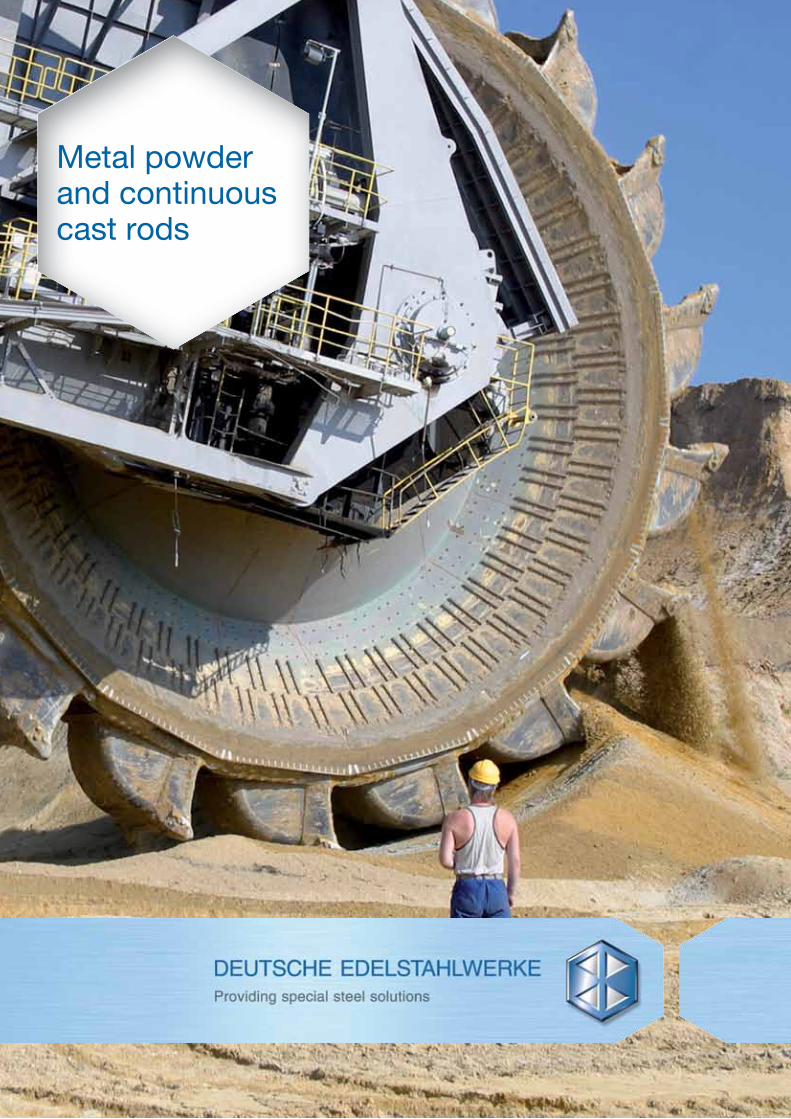
Metal powder and continuous cast rods
02
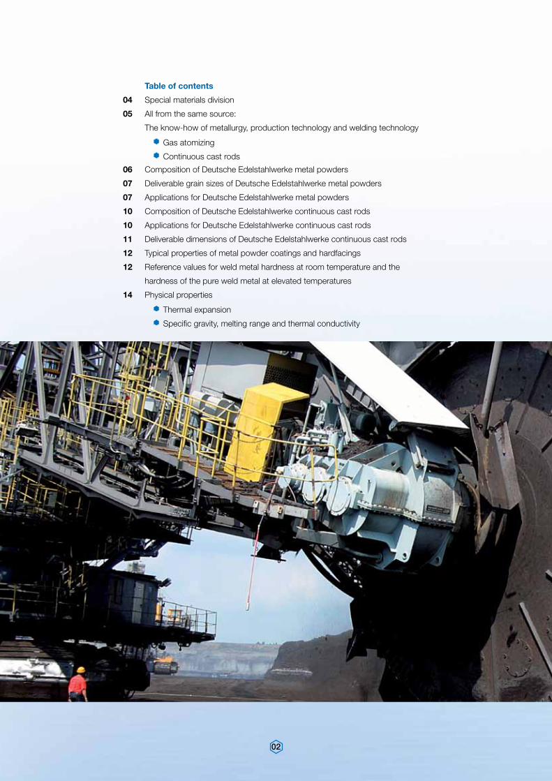
Table of contents
04 Special materials division
05 All from the same source:
The know-how of metallurgy, production technology and welding technology
Gas atomizing
Continuous cast rods
06 Composition of Deutsche Edelstahlwerke metal powders
07 Deliverable grain sizes of Deutsche Edelstahlwerke metal powders
07 Applications for Deutsche Edelstahlwerke metal powders
10 Composition of Deutsche Edelstahlwerke continuous cast rods
10 Applications for Deutsche Edelstahlwerke continuous cast rods
11 Deliverable dimensions of Deutsche Edelstahlwerke continuous cast rods
12 Typical properties of metal powder coatings and hardfacings
12 Reference values for weld metal hardness at room temperature and the
hardness of the pure weld metal at elevated temperatures
14 Physical properties
Thermal expansion
Specific gravity, melting range and thermal conductivity
03
15 Properties of coatings produced with Deutsche Edelstahlwerke metal powders
and continuous cast rods
16 Corrosion behaviour of Deutsche Edelstahlwerke metal powders and continuous cast rods
17 Application of Deutsche Edelstahlwerke metal powders and continuous cast rods
18 Practical tips regarding hardfacing
19 Metal powder coating and hardfacing processes
Plasma transferred arc welding (PTA)
Flame spray welding
Flame spraying
Plasma and high-velocity flame spraying (HVOF)
24 Hardfacing processes using continuous cast rods
Gas welding
TIG welding
26 Quality management
27 World wide presence
27 Global network
04
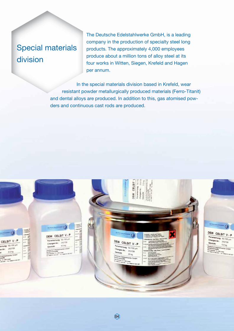
The Deutsche Edelstahlwerke GmbH, is a leading
company in the production of specialty steel long
products. The approximately 4,000 employees
produce about a million tons of alloy steel at its
four works in Witten, Siegen, Krefeld and Hagen
per annum.
In the special materials division based in Krefeld, wear
resistant powder metallurgically produced materials (Ferro-Titanit)
and dental alloys are produced. In addition to this, gas atomised pow-
ders and continuous cast rods are produced.
Special materials
division
05
Powder atomisation
Weld cladding is an important process when
the surfaces of a work piece need to be
modified to improve the wear and/or corrosion
properties.
The Deutsche Edelstahlwerke offer a wide pal-
let of Co, Ni and Fe base gas atomised metal
powders and continuous cast rods which are
suited for cladding, welding and thermal spray-
ing processes. These products are produced
using modern production facilities and benefit
from more than 160 years of metallurgical
knowledge in steel production.
In the gas atomising process, the raw mate-
rials are melted in an induction furnace prior to
being atomised with high pressure inert gas,
nitrogen, in the atomising tower. The nitrogen
atomises the metal stream entering the closed
tower and the resultant fine metal droplets fall
All from the same source: The know-how of metallurgy, production technology and welding technology
to the bottom of the tower where they are
collected. During the relatively slow solidifica-
tion process, compared with water atomisation,
the surface tension of the metal droplet pulls
the drop together to form the spherical ball
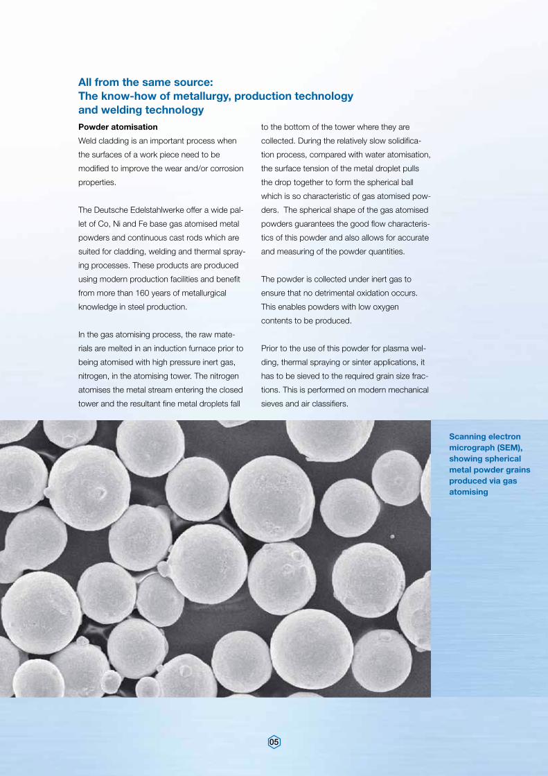
which is so characteristic of gas atomised pow-
ders. The spherical shape of the gas atomised
powders guarantees the good flow characteris-
tics of this powder and also allows for accurate
and measuring of the powder quantities.
The powder is collected under inert gas to
ensure that no detrimental oxidation occurs.
This enables powders with low oxygen
contents to be produced.
Prior to the use of this powder for plasma wel-
ding, thermal spraying or sinter applications, it
has to be sieved to the required grain size frac-
tions. This is performed on modern mechanical
sieves and air classifiers.
Scanning electron micrograph (SEM), showing spherical metal powder grains produced via gas atomising
06
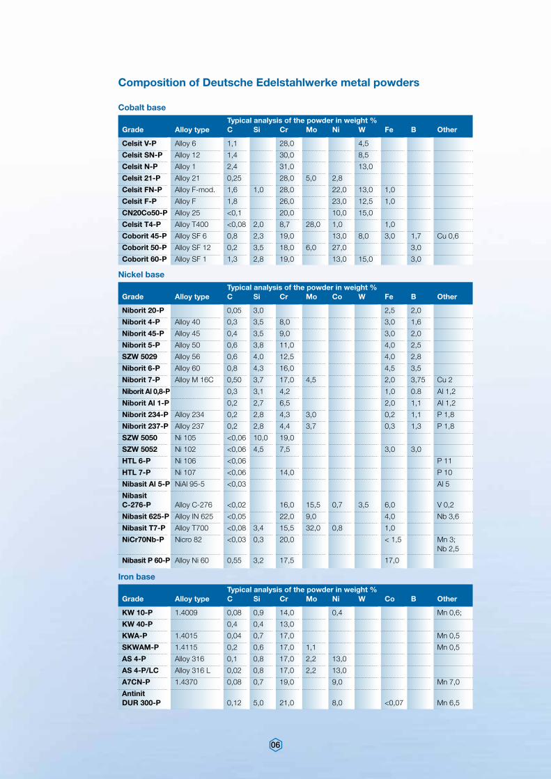
Typical analysis of the powder in weight %Grade Alloy type C Si Cr Mo Ni W Fe B Other
Typical analysis of the powder in weight %Grade Alloy type C Si Cr Mo Ni W Co B Other
Typical analysis of the powder in weight %Grade Alloy type C Si Cr Mo Co W Fe B Other
Celsit V-P Alloy 6 1,1 28,0 4,5
Celsit SN-P Alloy 12 1,4 30,0 8,5
Celsit N-P Alloy 1 2,4 31,0 13,0
Celsit 21-P Alloy 21 0,25 28,0 5,0 2,8
Celsit FN-P Alloy F-mod. 1,6 1,0 28,0 22,0 13,0 1,0
Celsit F-P Alloy F 1,8 26,0 23,0 12,5 1,0
CN20Co50-P Alloy 25 <0,1 20,0 10,0 15,0
Celsit T4-P Alloy T400 <0,08 2,0 8,7 28,0 1,0 1,0
Coborit 45-P Alloy SF 6 0,8 2,3 19,0 13,0 8,0 3,0 1,7 Cu 0,6
Coborit 50-P Alloy SF 12 0,2 3,5 18,0 6,0 27,0 3,0
Coborit 60-P Alloy SF 1 1,3 2,8 19,0 13,0 15,0 3,0
KW 10-P 1.4009 0,08 0,9 14,0 0,4 Mn 0,6;
KW 40-P 0,4 0,4 13,0
KWA-P 1.4015 0,04 0,7 17,0 Mn 0,5
SKWAM-P 1.4115 0,2 0,6 17,0 1,1 Mn 0,5
AS 4-P Alloy 316 0,1 0,8 17,0 2,2 13,0
AS 4-P/LC Alloy 316 L 0,02 0,8 17,0 2,2 13,0
A7CN-P 1.4370 0,08 0,7 19,0 9,0 Mn 7,0
Antinit DUR 300-P 0,12 5,0 21,0 8,0 <0,07 Mn 6,5
Niborit 20-P 0,05 3,0 2,5 2,0
Niborit 4-P Alloy 40 0,3 3,5 8,0 3,0 1,6
Niborit 45-P Alloy 45 0,4 3,5 9,0 3,0 2,0
Niborit 5-P Alloy 50 0,6 3,8 11,0 4,0 2,5
SZW 5029 Alloy 56 0,6 4,0 12,5 4,0 2,8
Niborit 6-P Alloy 60 0,8 4,3 16,0 4,5 3,5
Niborit 7-P Alloy M 16C 0,50 3,7 17,0 4,5 2,0 3,75 Cu 2
Niborit Al 0,8-P 0,3 3,1 4,2 1,0 0.8 Al 1,2
Niborit Al 1-P 0,2 2,7 6,5 2,0 1,1 Al 1,2
Niborit 234-P Alloy 234 0,2 2,8 4,3 3,0 0,2 1,1 P 1,8
Niborit 237-P Alloy 237 0,2 2,8 4,4 3,7 0,3 1,3 P 1,8
SZW 5050 Ni 105 <0,06 10,0 19,0
SZW 5052 Ni 102 <0,06 4,5 7,5 3,0 3,0
HTL 6-P Ni 106 <0,06 P 11
HTL 7-P Ni 107 <0,06 14,0 P 10
Nibasit Al 5-P NiAl 95-5 <0,03 Al 5
Nibasit C-276-P Alloy C-276 <0,02 16,0 15,5 0,7 3,5 6,0 V 0,2
Nibasit 625-P Alloy IN 625 <0,05 22,0 9,0 4,0 Nb 3,6
Nibasit T7-P Alloy T700 <0,08 3,4 15,5 32,0 0,8 1,0
NiCr70Nb-P Nicro 82 <0,03 0,3 20,0 < 1,5 Mn 3; Nb 2,5
Nibasit P 60-P Alloy Ni 60 0,55 3,2 17,5 17,0
Cobalt base
Iron base
Nickel base
Composition of Deutsche Edelstahlwerke metal powders
07
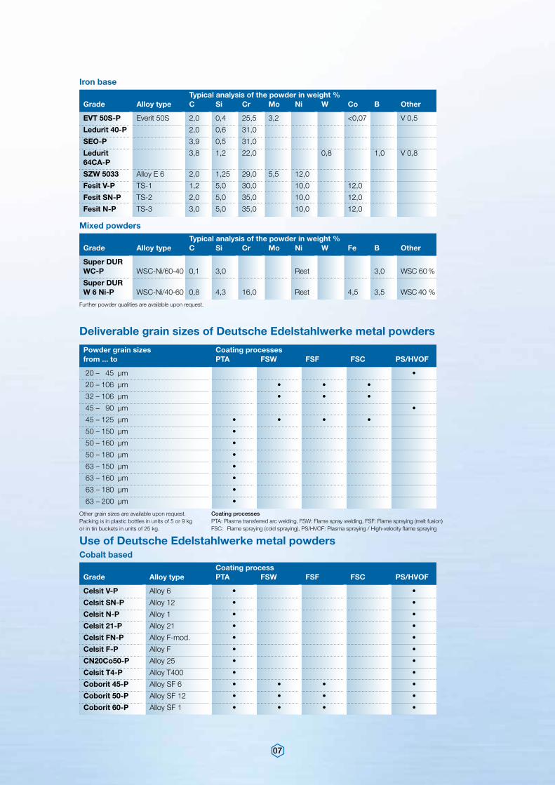
Typical analysis of the powder in weight %Grade Alloy type C Si Cr Mo Ni W Co B Other
Typical analysis of the powder in weight %Grade Alloy type C Si Cr Mo Ni W Fe B Other
EVT 50S-P Everit 50S 2,0 0,4 25,5 3,2 <0,07 V 0,5
Ledurit 40-P 2,0 0,6 31,0
SEO-P 3,9 0,5 31,0
Ledurit 3,8 1,2 22,0 0,8 1,0 V 0,8 64CA-P
SZW 5033 Alloy E 6 2,0 1,25 29,0 5,5 12,0
Fesit V-P TS-1 1,2 5,0 30,0 10,0 12,0
Fesit SN-P TS-2 2,0 5,0 35,0 10,0 12,0
Fesit N-P TS-3 3,0 5,0 35,0 10,0 12,0
Super DUR WC-P WSC-Ni/60-40 0,1 3,0 Rest 3,0 WSC 60 %
Super DUR W 6 Ni-P WSC-Ni/40-60 0,8 4,3 16,0 Rest 4,5 3,5 WSC 40 %
Iron base
Mixed powders
Further powder qualities are available upon request.
Deliverable grain sizes of Deutsche Edelstahlwerke metal powders
Powder grain sizes Coating processesfrom ... to PTA FSW FSF FSC PS/HVOF
20 – 45 µm •
20 – 106 µm • • •
32 – 106 µm • • •
45 – 90 µm •
45 – 125 µm • • • •
50 – 150 µm •
50 – 160 µm •
50 – 180 µm •
63 – 150 µm •
63 – 160 µm •
63 – 180 µm •
63 – 200 µm •
Other grain sizes are available upon request. Packing is in plastic bottles in units of 5 or 9 kg or in tin buckets in units of 25 kg.
Coating processesPTA: Plasma transferred arc welding, FSW: Flame spray welding, FSF: Flame spraying (melt fusion)FSC: Flame spraying (cold spraying), PS/HVOF: Plasma spraying / High-velocity flame spraying
Coating processGrade Alloy type PTA FSW FSF FSC PS/HVOF
Celsit V-P Alloy 6 • •
Celsit SN-P Alloy 12 • •
Celsit N-P Alloy 1 • •
Celsit 21-P Alloy 21 • •
Celsit FN-P Alloy F-mod. • •
Celsit F-P Alloy F • •
CN20Co50-P Alloy 25 • •
Celsit T4-P Alloy T400 • •
Coborit 45-P Alloy SF 6 • • • •
Coborit 50-P Alloy SF 12 • • • •
Coborit 60-P Alloy SF 1 • • • •
Cobalt based
Use of Deutsche Edelstahlwerke metal powders
08
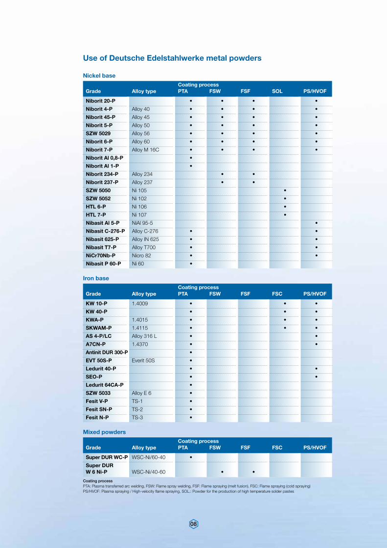
Coating processGrade Alloy type PTA FSW FSF SOL PS/HVOF
Niborit 20-P • • • •
Niborit 4-P Alloy 40 • • • •
Niborit 45-P Alloy 45 • • • •
Niborit 5-P Alloy 50 • • • •
SZW 5029 Alloy 56 • • • •
Niborit 6-P Alloy 60 • • • •
Niborit 7-P Alloy M 16C • • • •
Niborit Al 0,8-P •
Niborit Al 1-P •
Niborit 234-P Alloy 234 • •
Niborit 237-P Alloy 237 • •
SZW 5050 Ni 105 •
SZW 5052 Ni 102 •
HTL 6-P Ni 106 •
HTL 7-P Ni 107 •
Nibasit Al 5-P NiAl 95-5 •
Nibasit C-276-P Alloy C-276 • •
Nibasit 625-P Alloy IN 625 • •
Nibasit T7-P Alloy T700 • •
NiCr70Nb-P Nicro 82 • •
Nibasit P 60-P Ni 60 •
Nickel base
Coating processGrade Alloy type PTA FSW FSF FSC PS/HVOF
Coating processGrade Alloy type PTA FSW FSF FSC PS/HVOF
KW 10-P 1.4009 • • •
KW 40-P • • •
KWA-P 1.4015 • • •
SKWAM-P 1.4115 • • •
AS 4-P/LC Alloy 316 L • •
A7CN-P 1.4370 • •
Antinit DUR 300-P •
EVT 50S-P Everit 50S •
Ledurit 40-P • •
SEO-P • •
Ledurit 64CA-P •
SZW 5033 Alloy E 6 •
Fesit V-P TS-1 •
Fesit SN-P TS-2 •
Fesit N-P TS-3 •
Super DUR WC-P WSC-Ni/60-40 •
Super DUR W 6 Ni-P WSC-Ni/40-60 • •
Iron base
Mixed powders
Coating processPTA: Plasma transferred arc welding, FSW: Flame spray welding, FSF: Flame spraying (melt fusion), FSC: Flame spraying (cold spraying)PS/HVOF: Plasma spraying / High-velocity flame spraying, SOL.: Powder for the production of high temperature solder pastes
Use of Deutsche Edelstahlwerke metal powders
09
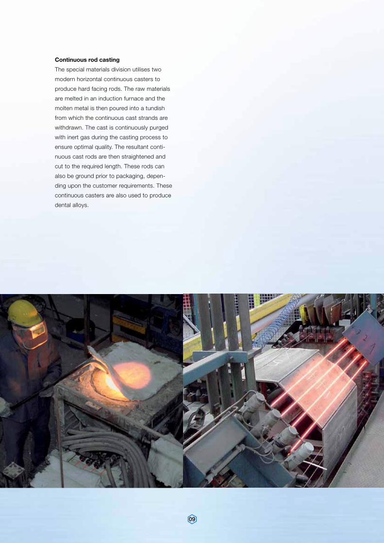
Continuous rod casting
The special materials division utilises two
modern horizontal continuous casters to
produce hard facing rods. The raw materials
are melted in an induction furnace and the
molten metal is then poured into a tundish
from which the continuous cast strands are
withdrawn. The cast is continuously purged
with inert gas during the casting process to
ensure optimal quality. The resultant conti-
nuous cast rods are then straightened and
cut to the required length. These rods can
also be ground prior to packaging, depen-
ding upon the customer requirements. These
continuous casters are also used to produce
dental alloys.
10
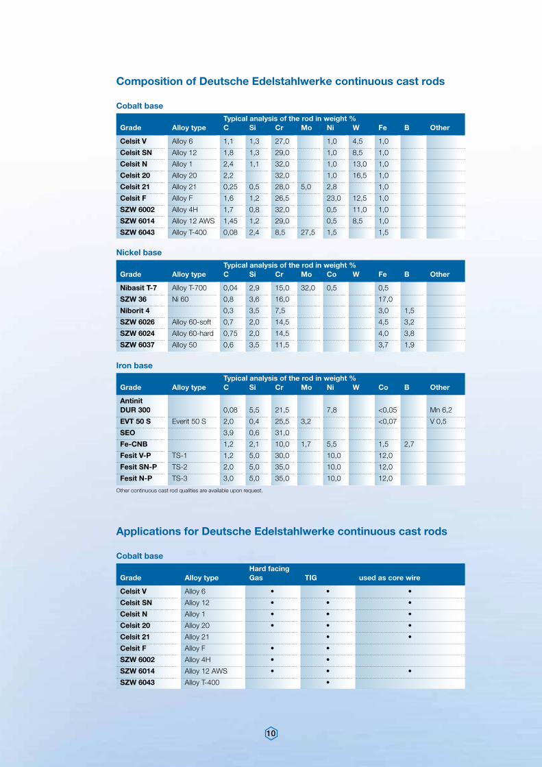
Hard facing Grade Alloy type Gas TIG used as core wire
Celsit V Alloy 6 • • •
Celsit SN Alloy 12 • • •
Celsit N Alloy 1 • • •
Celsit 20 Alloy 20 • • •
Celsit 21 Alloy 21 • •
Celsit F Alloy F • •
SZW 6002 Alloy 4H • •
SZW 6014 Alloy 12 AWS • • •
SZW 6043 Alloy T-400 •
Cobalt base
Applications for Deutsche Edelstahlwerke continuous cast rods
Typical analysis of the rod in weight %Grade Alloy type C Si Cr Mo Ni W Fe B Other
Typical analysis of the rod in weight %Grade Alloy type C Si Cr Mo Co W Fe B Other
Celsit V Alloy 6 1,1 1,3 27,0 1,0 4,5 1,0
Celsit SN Alloy 12 1,8 1,3 29,0 1,0 8,5 1,0
Celsit N Alloy 1 2,4 1,1 32,0 1,0 13,0 1,0
Celsit 20 Alloy 20 2,2 32,0 1,0 16,5 1,0
Celsit 21 Alloy 21 0,25 0,5 28,0 5,0 2,8 1,0
Celsit F Alloy F 1,6 1,2 26,5 23,0 12,5 1,0
SZW 6002 Alloy 4H 1,7 0,8 32,0 0,5 11,0 1,0
SZW 6014 Alloy 12 AWS 1,45 1,2 29,0 0,5 8,5 1,0
SZW 6043 Alloy T-400 0,08 2,4 8,5 27,5 1,5 1,5
Nibasit T-7 Alloy T-700 0,04 2,9 15,0 32,0 0,5 0,5
SZW 36 Ni 60 0,8 3,6 16,0 17,0
Niborit 4 0,3 3,5 7,5 3,0 1,5
SZW 6026 Alloy 60-soft 0,7 2,0 14,5 4,5 3,2
SZW 6024 Alloy 60-hard 0,75 2,0 14,5 4,0 3,8
SZW 6037 Alloy 50 0,6 3,5 11,5 3,7 1,9
Cobalt base
Nickel base
Composition of Deutsche Edelstahlwerke continuous cast rods
Typical analysis of the rod in weight %Grade Alloy type C Si Cr Mo Ni W Co B Other
Antinit DUR 300 0,08 5,5 21,5 7,8 <0,05 Mn 6,2
EVT 50 S Everit 50 S 2,0 0,4 25,5 3,2 <0,07 V 0,5
SEO 3,9 0,6 31,0
Fe-CNB 1,2 2,1 10,0 1,7 5,5 1,5 2,7
Fesit V-P TS-1 1,2 5,0 30,0 10,0 12,0
Fesit SN-P TS-2 2,0 5,0 35,0 10,0 12,0
Fesit N-P TS-3 3,0 5,0 35,0 10,0 12,0
Iron base
Other continuous cast rod qualities are available upon request.
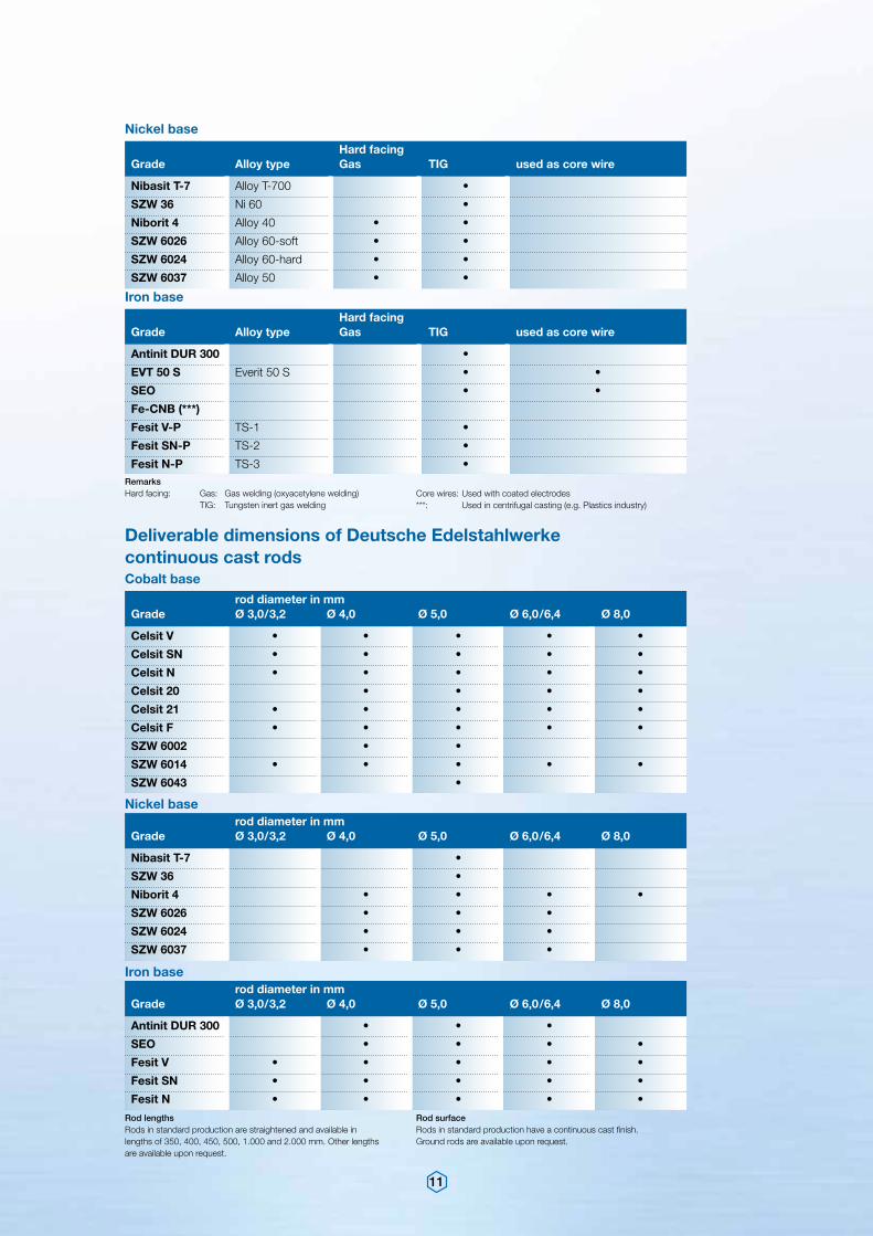
11
Hard facing Grade Alloy type Gas TIG used as core wire
Hard facing Grade Alloy type Gas TIG used as core wire
Nibasit T-7 Alloy T-700 •
SZW 36 Ni 60 •
Niborit 4 Alloy 40 • •
SZW 6026 Alloy 60-soft • •
SZW 6024 Alloy 60-hard • •
SZW 6037 Alloy 50 • •
Antinit DUR 300 •
EVT 50 S Everit 50 S • •
SEO • •
Fe-CNB (***)
Fesit V-P TS-1 •
Fesit SN-P TS-2 •
Fesit N-P TS-3 •
Nickel base
Iron base
RemarksHard facing: Gas: Gas welding (oxyacetylene welding) TIG: Tungsten inert gas welding
Core wires: Used with coated electrodes***: Used in centrifugal casting (e.g. Plastics industry)
rod diameter in mmGrade Ø 3,0/3,2 Ø 4,0 Ø 5,0 Ø 6,0/6,4 Ø 8,0
rod diameter in mmGrade Ø 3,0/3,2 Ø 4,0 Ø 5,0 Ø 6,0/6,4 Ø 8,0
rod diameter in mmGrade Ø 3,0/3,2 Ø 4,0 Ø 5,0 Ø 6,0/6,4 Ø 8,0
Celsit V • • • • •
Celsit SN • • • • •
Celsit N • • • • •
Celsit 20 • • • •
Celsit 21 • • • • •
Celsit F • • • • •
SZW 6002 • •
SZW 6014 • • • • •
SZW 6043 •
Nibasit T-7 •
SZW 36 •
Niborit 4 • • • •
SZW 6026 • • •
SZW 6024 • • •
SZW 6037 • • •
Antinit DUR 300 • • •
SEO • • • •
Fesit V • • • • •
Fesit SN • • • • •
Fesit N • • • • •
Cobalt base
Nickel base
Iron base
Deliverable dimensions of Deutsche Edelstahlwerke continuous cast rods
Rod lengthsRods in standard production are straightened and available in lengths of 350, 400, 450, 500, 1.000 and 2.000 mm. Other lengths are available upon request.
Rod surfaceRods in standard production have a continuous cast finish.Ground rods are available upon request.
12
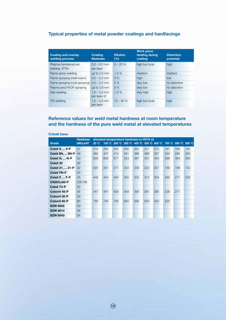
Hardness Grade (HRC) at RT
elevated temperature hardness in HV10 at 20 °C 100 °C 200 °C 300 °C 400 °C 500 °C 600 °C 700 °C 800 °C 900 °C
Celsit V, ... V-P 41
Celsit SN, ... SN-P 48
Celsit N, ... N-P 53
Celsit 20 56
Celsit 21, ... 21-P 32
Celsit FN-P 43
Celsit F, ... F-P 45
CN20Co50-P 230 HB
Celsit T4-P 55
Coborit 45-P 45
Coborit 50-P 50
Coborit 60-P 60
SZW 6002 53
SZW 6014 46
SZW 6043 54
410 394 344 330 322 311 272 197 180 152
485 447 412 401 388 368 357 333 285 230
626 605 571 523 487 451 445 386 304 263
325 291 271 254 239 222 201 186 166 150
446 442 400 355 333 315 304 295 271 228
447 447 428 409 390 361 295 238 271
760 740 700 650 580 500 420 225
Cobalt base
Reference values for weld metal hardness at room temperature and the hardness of the pure weld metal at elevated temperatures
Work piece Coating and overlay Coating Dilution heating during Distortionwelding process thickness (%) coating potential
Plasma-transferred-arc 2,0 – 6,0 mm 5 – 20 % high but local high welding (PTA) per layer
Flame spray welding up to 2,0 mm < 5 % medium medium
Flame spraying (melt fusion) 0,5 – 2,0 mm 0 % high low
Flame spraying (cold spraying) 0,5 – 2,0 mm 0 % very low no distortion
Plasma and HVOF-spraying up to 0,8 mm 0 % very low no distortion
Gas welding 1,5 – 5,0 mm < 5 % very high high per layer of
TIG welding 1,5 – 5,0 mm 10 – 30 % high but local high per layer
Typical properties of metal powder coatings and hardfacings
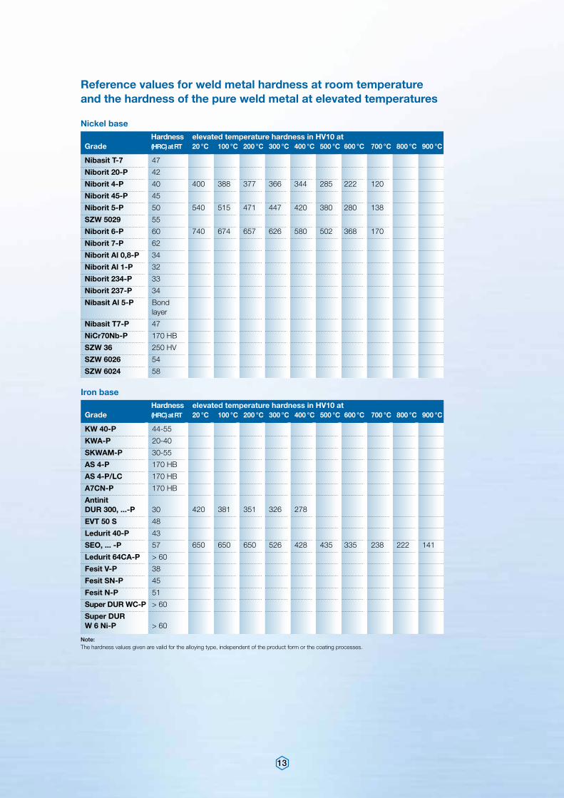
13
Hardness Grade (HRC) at RT
Hardness Grade (HRC) at RT
elevated temperature hardness in HV10 at 20 °C 100 °C 200 °C 300 °C 400 °C 500 °C 600 °C 700 °C 800 °C 900 °C
elevated temperature hardness in HV10 at 20 °C 100 °C 200 °C 300 °C 400 °C 500 °C 600 °C 700 °C 800 °C 900 °C
KW 40-P 44-55
KWA-P 20-40
SKWAM-P 30-55
AS 4-P 170 HB
AS 4-P/LC 170 HB
A7CN-P 170 HB
Antinit DUR 300, ...-P 30
EVT 50 S 48
Ledurit 40-P 43
SEO, ... -P 57
Ledurit 64CA-P > 60
Fesit V-P 38
Fesit SN-P 45
Fesit N-P 51
Super DUR WC-P > 60
Super DUR W 6 Ni-P > 60
Nibasit T-7 47
Niborit 20-P 42
Niborit 4-P 40
Niborit 45-P 45
Niborit 5-P 50
SZW 5029 55
Niborit 6-P 60
Niborit 7-P 62
Niborit Al 0,8-P 34
Niborit Al 1-P 32
Niborit 234-P 33
Niborit 237-P 34
Nibasit Al 5-P Bond layer
Nibasit T7-P 47
NiCr70Nb-P 170 HB
SZW 36 250 HV
SZW 6026 54
SZW 6024 58
420 381 351 326 278
650 650 650 526 428 435 335 238 222 141
400 388 377 366 344 285 222 120
540 515 471 447 420 380 280 138
740 674 657 626 580 502 368 170
Iron base
Nickel base
Reference values for weld metal hardness at room temperature and the hardness of the pure weld metal at elevated temperatures
Note:The hardness values given are valid for the alloying type, independent of the product form or the coating processes.
14
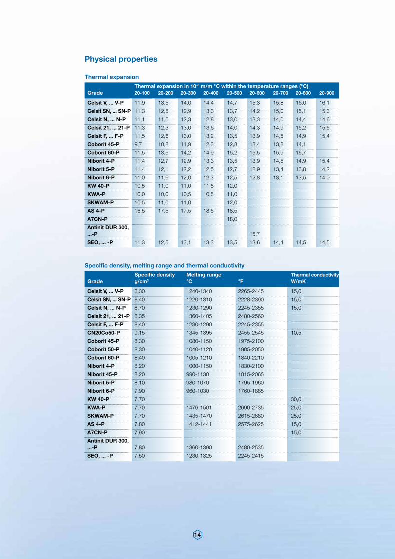
Thermal expansion in 10-6 m/m °C within the temperature ranges (°C)Grade 20-100 20-200 20-300 20-400 20-500 20-600 20-700 20-800 20-900
Specific density Melting range Thermal conductivity Grade g/cm3 °C °F W/mK
Celsit V, ... V-P 11,9 13,5 14,0 14,4 14,7 15,3 15,8 16,0 16,1
Celsit SN, ... SN-P 11,3 12,5 12,9 13,3 13,7 14,2 15,0 15,1 15,3
Celsit N, ... N-P 11,1 11,6 12,3 12,8 13,0 13,3 14,0 14,4 14,6
Celsit 21, ... 21-P 11,3 12,3 13,0 13,6 14,0 14,3 14,9 15,2 15,5
Celsit F, ... F-P 11,5 12,6 13,0 13,2 13,5 13,9 14,5 14,9 15,4
Coborit 45-P 9,7 10,8 11,9 12,3 12,8 13,4 13,8 14,1
Coborit 60-P 11,5 13,6 14,2 14,9 15,2 15,5 15,9 16,7
Niborit 4-P 11,4 12,7 12,9 13,3 13,5 13,9 14,5 14,9 15,4
Niborit 5-P 11,4 12,1 12,2 12,5 12,7 12,9 13,4 13,8 14,2
Niborit 6-P 11,0 11,6 12,0 12,3 12,5 12,8 13,1 13,5 14,0
KW 40-P 10,5 11,0 11,0 11,5 12,0
KWA-P 10,0 10,0 10,5 10,5 11,0
SKWAM-P 10,5 11,0 11,0 12,0
AS 4-P 16,5 17,5 17,5 18,5 18,5
A7CN-P 18,0
Antinit DUR 300, ...-P 15,7
SEO, ... -P 11,3 12,5 13,1 13,3 13,5 13,6 14,4 14,5 14,5
Celsit V, ... V-P 8,30 1240-1340 2265-2445 15,0
Celsit SN, ... SN-P 8,40 1220-1310 2228-2390 15,0
Celsit N, ... N-P 8,70 1230-1290 2245-2355 15,0
Celsit 21, ... 21-P 8,35 1360-1405 2480-2560
Celsit F, ... F-P 8,40 1230-1290 2245-2355
CN20Co50-P 9,15 1345-1395 2455-2545 10,5
Coborit 45-P 8,30 1080-1150 1975-2100
Coborit 50-P 8,30 1040-1120 1905-2050
Coborit 60-P 8,40 1005-1210 1840-2210
Niborit 4-P 8,20 1000-1150 1830-2100
Niborit 45-P 8,20 990-1130 1815-2065
Niborit 5-P 8,10 980-1070 1795-1960
Niborit 6-P 7,90 960-1030 1760-1885
KW 40-P 7,70 30,0
KWA-P 7,70 1476-1501 2690-2735 25,0
SKWAM-P 7,70 1435-1470 2615-2680 25,0
AS 4-P 7,80 1412-1441 2575-2625 15,0
A7CN-P 7,90 15,0
Antinit DUR 300, ...-P 7,80 1360-1390 2480-2535
SEO, ... -P 7,50 1230-1325 2245-2415
Thermal expansion
Specific density, melting range and thermal conductivity
Physical properties
15
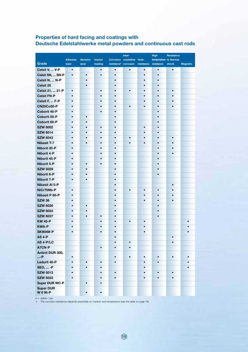
Inter- High Resistance
Adhesive Abrasive Impact Corrosion crystalline Heat- temperature to thermal
Grade wear wear loading resistance* corrosion resistance resistance shock Magnetic
Celsit V, ... V-P • • • • • • •
Celsit SN, ... SN-P • • • • • •
Celsit N, ... N-P • • • •
Celsit 20 • • • •
Celsit 21, ... 21-P • • • • • • •
Celsit FN-P • • • • • •
Celsit F, ... F-P • • • • • •
CN20Co50-P • • • • • • •
Coborit 45-P • • • •
Coborit 50-P • • • •
Coborit 60-P • • • •
SZW 6002 • • • • • •
SZW 6014 • • • • • •
SZW 6043 • • • • • • • •
Nibasit T-7 • • • • • • • •
Niborit 20-P • • • • •
Niborit 4-P • • • • •
Niborit 45-P • • • •
Niborit 5-P • • • • •
SZW 5029 • • • •
Niborit 6-P • • • •
Niborit 7-P • • •
Nibasit Al 5-P • •
NiCr70Nb-P • • • • • •
Nibasit P 60-P • • • • •
SZW 36 • • • • •
SZW 6026 • • • •
SZW 6024 • • • •
SZW 6037 • • • • •
KW 40-P • • • • • •
KWA-P • • • • •
SKWAM-P • • • • •
AS 4-P • •
AS 4-P/LC • • •
A7CN-P • • •
Antinit DUR 300, ...-P • • • • • • •
Ledurit 40-P • • • • • • •
SEO, ... -P • • • • •
SZW 5013 • • • • • •
SZW 5033 • • • • • •
Super DUR WC-P • •
Super DUR W 6 Ni-P • •
Properties of hard facing and coatings with Deutsche Edelstahlwerke metal powders and continuous cast rods
• = stable / yes*) The corrosion resistance depends essentially on medium and temperature (see the table on page 16).
16
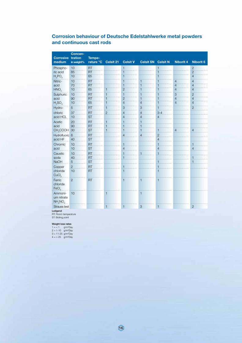
Concen- Corrosive tration Tempe-medium in weight% rature °C Celsit 21 Celsit V Celsit SN Celsit N Niborit 4 Niborit 6
Phospho- 10 RT 1 1 2ric acid 85 RT 1 1 2H3PO4 10 65 1 1 4
Nitric- 10 RT 1 1 1 4 4acid 70 RT 1 1 1 4 4HNO3 10 65 1 2 1 1 4 4
Sulphuric 10 RT 1 1 1 1 3 2acid 90 RT 1 2 1 1 4 4H2SO4 10 65 1 4 4 1 4 4
Hydro- 5 RT 1 3 3 1 2
chloric 37 RT 2 4 4 3-4 acid HCL 10 ST 4 4 4
Acetic 20 RT 1 1 1 acid 90 RT 1 1 1 CH3COOH 30 ST 1 1 1 1 4 4
Hydrofluoric 6 RT 4 4 2 acid HF 40 ST 4
Chromic 10 RT 1 1 1acid 10 ST 4 4 4
Caustic 10 RT 1 1 1 soda 40 RT 1 1NaOH 5 ST 1 1
Copper 2 RT 1 1 chloride 10 RT 1 1 CuCl2Ferric 2 RT 1 1 1 chloride FeCl3Ammoni- 10 1 1 um nitrateNH4NO3
Strauss test 1 1 3 1 2
Corrosion behaviour of Deutsche Edelstahlwerke metal powders and continuous cast rods
LedgendRT: Room temperatureST: Boiling point
Weight loss rates1 = < 1 g/m2Day2 = 1-10 g/m2Day3 = 11-25 g/m2Day4 = > 25 g/m2Day
17
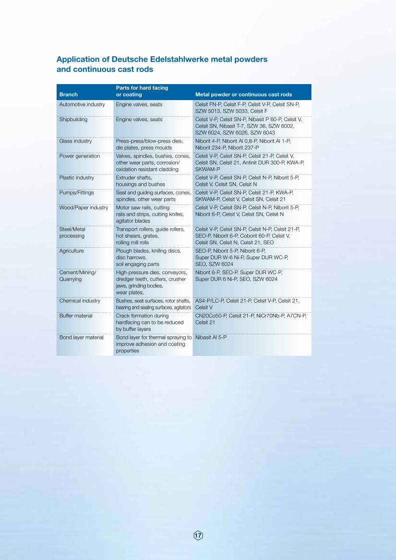
Parts for hard facing Branch or coating Metal powder or continuous cast rods
Automotive industry Engine valves, seats Celsit FN-P, Celsit F-P, Celsit V-P, Celsit SN-P, SZW 5013, SZW 5033, Celsit F
Shipbuilding Engine valves, seats Celsit V-P, Celsit SN-P, Nibasit P 60-P, Celsit V, Celsit SN, Nibasit T-7, SZW 36, SZW 6002, SZW 6024, SZW 6026, SZW 6043
Glass industry Press-press/blow-press dies, Niborit 4-P, Niborit Al 0,8-P, Niborit Al 1-P, die plates, press moulds Niborit 234-P, Niborit 237-P
Power generation Valves, spindles, bushes, cones, Celsit V-P, Celsit SN-P, Celsit 21-P, Celsit V, other wear parts, corrosion/ Celsit SN, Celsit 21, Antinit DUR 300-P, KWA-P, oxidation resistant cladding SKWAM-P
Plastic industry Extruder shafts, Celsit V-P, Celsit SN-P, Celsit N-P, Niborit 5-P, housings and bushes Celsit V, Celsit SN, Celsit N
Pumps/Fittings Seat and guiding surfaces, cones, Celsit V-P, Celsit SN-P, Celsit 21-P, KWA-P, spindles, other wear parts SKWAM-P, Celsit V, Celsit SN, Celsit 21
Wood/Paper industry Motor saw rails, cutting Celsit V-P, Celsit SN-P, Celsit N-P, Niborit 5-P, rails and strips, cutting knifes, Niborit 6-P, Celsit V, Celsit SN, Celsit N agitator blades
Steel/Metal Transport rollers, guide rollers, Celsit V-P, Celsit SN-P, Celsit N-P, Celsit 21-P,processing hot shears, grates, SEO-P, Niborit 6-P, Coborit 60-P, Celsit V, rolling mill rolls Celsit SN, Celsit N, Celsit 21, SEO
Agriculture Plough blades, knifing discs, SEO-P, Niborit 5-P, Niborit 6-P, disc harrows, Super DUR W-6 Ni-P, Super DUR WC-P, soil engaging parts SEO, SZW 6024
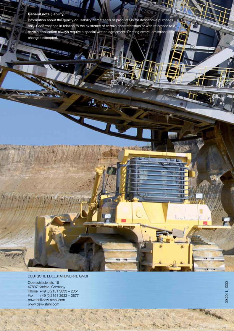
Cement/Mining/ High-pressure dies, conveyors, Niborit 6-P, SEO-P, Super DUR WC-P,Quarrying dredger teeth, cutters, crusher Super DUR 6 Ni-P, SEO, SZW 6024 jaws, grinding bodies, wear plates,
Chemical industry Bushes, seat surfaces, rotor shafts, AS4-P/LC-P, Celsit 21-P, Celsit V-P, Celsit 21, bearing and sealing surfaces, agitators Celsit V
Buffer material Crack formation during CN20Co50-P, Celsit 21-P, NiCr70Nb-P, A7CN-P, hardfacing can to be reduced Celsit 21 by buffer layers
Bond layer material Bond layer for thermal spraying to Nibasit Al 5-P improve adhesion and coating properties
Application of Deutsche Edelstahlwerke metal powders and continuous cast rods
18
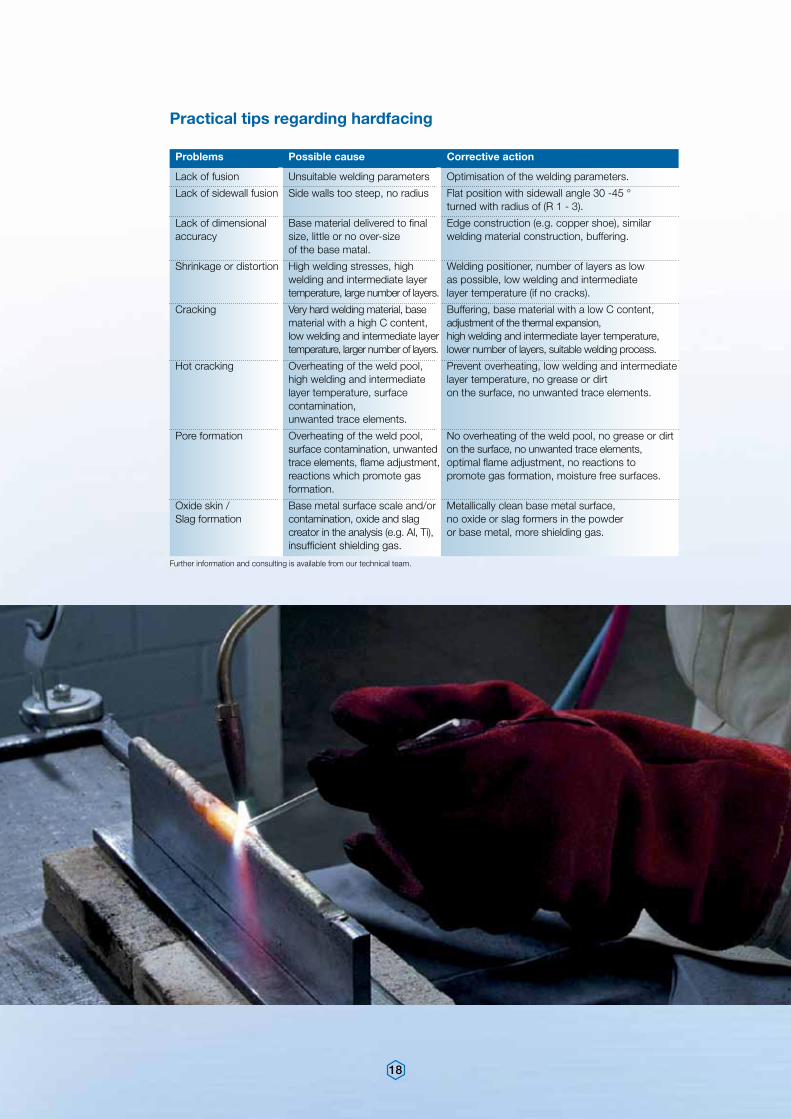
Problems Possible cause Corrective action
Lack of fusion Unsuitable welding parameters Optimisation of the welding parameters.
Lack of sidewall fusion Side walls too steep, no radius Flat position with sidewall angle 30 -45 ° turned with radius of (R 1 - 3).
Lack of dimensional Base material delivered to final Edge construction (e.g. copper shoe), similar accuracy size, little or no over-size welding material construction, buffering. of the base matal.
Shrinkage or distortion High welding stresses, high Welding positioner, number of layers as low welding and intermediate layer as possible, low welding and intermediate temperature, large number of layers. layer temperature (if no cracks).
Cracking Very hard welding material, base Buffering, base material with a low C content, material with a high C content, adjustment of the thermal expansion, low welding and intermediate layer high welding and intermediate layer temperature, temperature, larger number of layers. lower number of layers, suitable welding process.
Hot cracking Overheating of the weld pool, Prevent overheating, low welding and intermediate high welding and intermediate layer temperature, no grease or dirt layer temperature, surface on the surface, no unwanted trace elements. contamination, unwanted trace elements.
Pore formation Overheating of the weld pool, No overheating of the weld pool, no grease or dirt surface contamination, unwanted on the surface, no unwanted trace elements, trace elements, flame adjustment, optimal flame adjustment, no reactions to reactions which promote gas promote gas formation, moisture free surfaces. formation.
Oxide skin / Base metal surface scale and/or Metallically clean base metal surface, Slag formation contamination, oxide and slag no oxide or slag formers in the powder creator in the analysis (e.g. Al, Ti), or base metal, more shielding gas. insufficient shielding gas.
Practical tips regarding hardfacing
Further information and consulting is available from our technical team.
Ar Ar
19
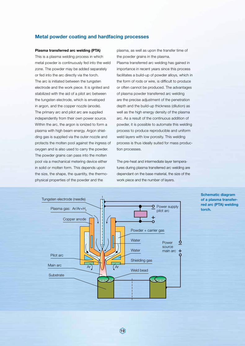
plasma, as well as upon the transfer time of
the powder grains in the plasma.
Plasma transferred arc welding has gained in
importance in recent years since this process
facilitates a build-up of powder alloys, which in
the form of rods or wire, is difficult to produce
or often cannot be produced. The advantages
of plasma powder transferred arc welding
are the precise adjustment of the penetration
depth and the build-up thickness (dilution) as
well as the high energy density of the plasma
arc. As a result of the continuous addition of
powder, it is possible to automate this welding
process to produce reproducible and uniform
weld layers with low porosity. This welding
process is thus ideally suited for mass produc-
tion processes.
The pre-heat and intermediate layer tempera-
tures during plasma transferred arc welding are
dependant on the base material, the size of the
work piece and the number of layers.
Plasma transferred arc welding (PTA)
This is a plasma welding process in which
metal powder is continuously fed into the weld
zone. The powder may be added separately
or fed into the arc directly via the torch.
The arc is initiated between the tungsten
electrode and the work piece. It is ignited and
stabilized with the aid of a pilot arc between
the tungsten electrode, which is enveloped
in argon, and the copper nozzle (anode).
The primary arc and pilot arc are supplied
independently from their own power source.
Within the arc, the argon is ionized to form a
plasma with high beam energy. Argon shiel-
ding gas is supplied via the outer nozzle and
protects the molten pool against the ingress of
oxygen and is also used to carry the powder.
The powder grains can pass into the molten
pool via a mechanical metering device either
in solid or molten form. This depends upon
the size, the shape, the quantity, the thermo-
physical properties of the powder and the
Schematic diagram of a plasma transfer-red arc (PTA) welding torch.
Metal powder coating and hardfacing processes
Tungsten electrode (needle)
Plasma gas: Ar/Ar+H2
Copper anode
Pilot arc
Main arc
Substrate
Water
Water
Powder + carrier gas
Shielding gas
Weld bead
Power supply pilot arc
Power source main arc
20
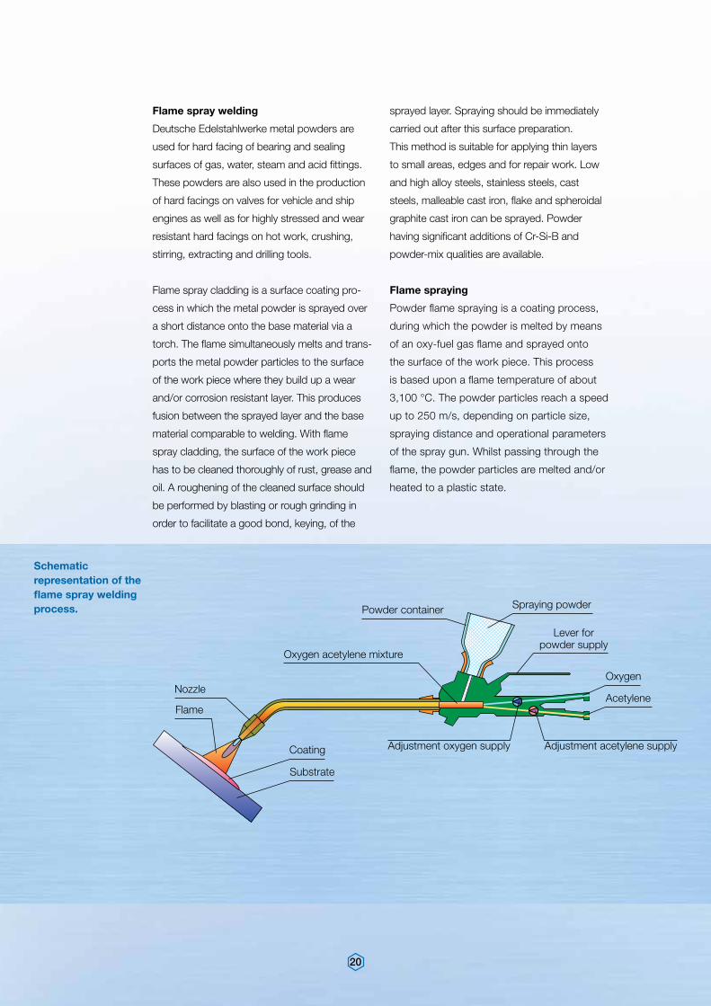
Schematic representation of the flame spray welding process.
sprayed layer. Spraying should be immediately
carried out after this surface preparation.
This method is suitable for applying thin layers
to small areas, edges and for repair work. Low
and high alloy steels, stainless steels, cast
steels, malleable cast iron, flake and spheroidal
graphite cast iron can be sprayed. Powder
having significant additions of Cr-Si-B and
powder-mix qualities are available.
Flame spraying
Powder flame spraying is a coating process,
during which the powder is melted by means
of an oxy-fuel gas flame and sprayed onto
the surface of the work piece. This process
is based upon a flame temperature of about
3,100 °C. The powder particles reach a speed
up to 250 m/s, depending on particle size,
spraying distance and operational parameters
of the spray gun. Whilst passing through the
flame, the powder particles are melted and/or
heated to a plastic state.
Flame spray welding
Deutsche Edelstahlwerke metal powders are
used for hard facing of bearing and sealing
surfaces of gas, water, steam and acid fittings.
These powders are also used in the production
of hard facings on valves for vehicle and ship
engines as well as for highly stressed and wear
resistant hard facings on hot work, crushing,
stirring, extracting and drilling tools.
Flame spray cladding is a surface coating pro-
cess in which the metal powder is sprayed over
a short distance onto the base material via a
torch. The flame simultaneously melts and trans-
ports the metal powder particles to the surface
of the work piece where they build up a wear
and/or corrosion resistant layer. This produces
fusion between the sprayed layer and the base
material comparable to welding. With flame
spray cladding, the surface of the work piece
has to be cleaned thoroughly of rust, grease and
oil. A roughening of the cleaned surface should
be performed by blasting or rough grinding in
order to facilitate a good bond, keying, of the
Nozzle
Flame
Coating
Substrate
Oxygen acetylene mixture
Powder container
Adjustment oxygen supply Adjustment acetylene supply
Acetylene
Oxygen
Spraying powder
Lever for powder supply
21
nated. All conventional powder alloys used
industrially can be sprayed.
With the powder flame spraying process with
subsequent fusing-in (melt fusion), the applied
metallic sprayed layers are subsequently
sintered at temperatures of 1,000 to 1,200 °C.
This subsequent treatment can either be
carried out with the aid of torches, furnaces
or by induction. For this process only the
so-called self-flowing alloys with a nickel base
or cobalt base are used. In these alloys the
addition of boron and silicon aid the fusing
process. Through the fusing process dense
sprayed layers are produced and have
considerably improved properties in respect
of homogeneity, adhesion and surface rough-
ness. Fields of application for these powder
flame spraying processes are to be found,
in the chemical, glass, plastic and electrical
industry as well as in machine, pump and
compressor constructions.
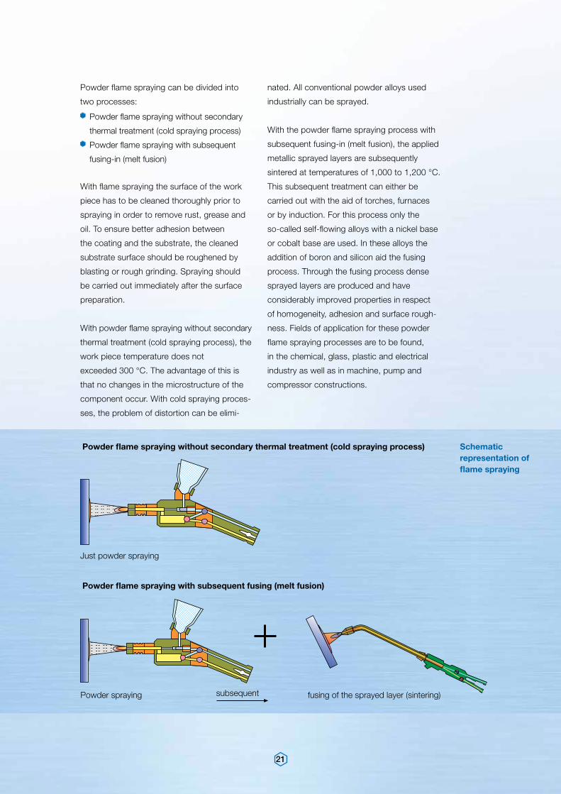
Schematic representation of flame spraying
Powder flame spraying can be divided into
two processes:
Powder flame spraying without secondary
thermal treatment (cold spraying process)
Powder flame spraying with subsequent
fusing-in (melt fusion)
With flame spraying the surface of the work
piece has to be cleaned thoroughly prior to
spraying in order to remove rust, grease and
oil. To ensure better adhesion between
the coating and the substrate, the cleaned
substrate surface should be roughened by
blasting or rough grinding. Spraying should
be carried out immediately after the surface
preparation.
With powder flame spraying without secondary
thermal treatment (cold spraying process), the
work piece temperature does not
exceeded 300 °C. The advantage of this is
that no changes in the microstructure of the
component occur. With cold spraying proces-
ses, the problem of distortion can be elimi-
subsequent
Powder flame spraying without secondary thermal treatment (cold spraying process)
Powder flame spraying with subsequent fusing (melt fusion)
Just powder spraying
Powder spraying fusing of the sprayed layer (sintering)
22
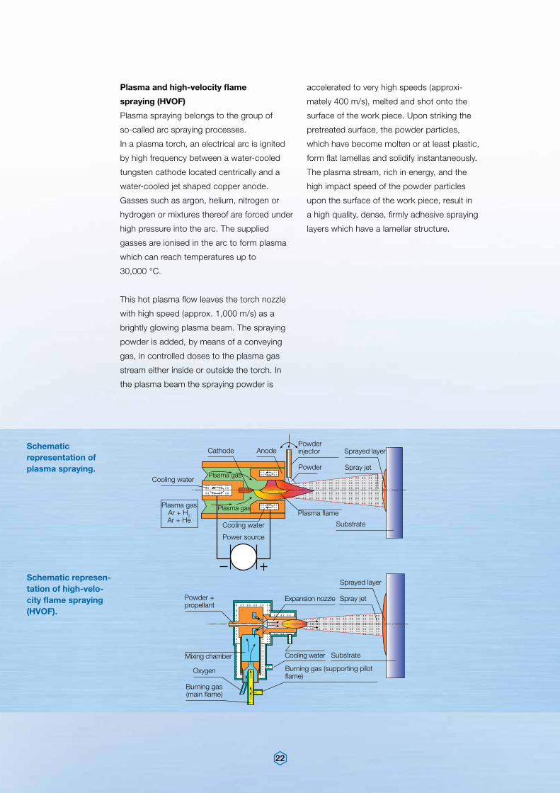
Plasma and high-velocity flame
spraying (HVOF)
Plasma spraying belongs to the group of
so-called arc spraying processes.
In a plasma torch, an electrical arc is ignited
by high frequency between a water-cooled
tungsten cathode located centrically and a
water-cooled jet shaped copper anode.
Gasses such as argon, helium, nitrogen or
hydrogen or mixtures thereof are forced under
high pressure into the arc. The supplied
gasses are ionised in the arc to form plasma
which can reach temperatures up to
30,000 °C.
This hot plasma flow leaves the torch nozzle
with high speed (approx. 1,000 m/s) as a
brightly glowing plasma beam. The spraying
powder is added, by means of a conveying
gas, in controlled doses to the plasma gas
stream either inside or outside the torch. In
the plasma beam the spraying powder is
accelerated to very high speeds (approxi-
mately 400 m/s), melted and shot onto the
surface of the work piece. Upon striking the
pretreated surface, the powder particles,
which have become molten or at least plastic,
form flat lamellas and solidify instantaneously.
The plasma stream, rich in energy, and the
high impact speed of the powder particles
upon the surface of the work piece, result in
a high quality, dense, firmly adhesive spraying
layers which have a lamellar structure.
Schematic representation of plasma spraying.
Schematic represen-tation of high-velo-city flame spraying (HVOF).
Cooling water
Power source
Plasma gasAr + H2Ar + He
Cooling water
Cathode Anode
Plasma gas
Plasma gas
Powder
Powder injector Sprayed layer
Spray jet
Substrate
Plasma flame
Sprayed layer
Spray jet
Substrate
Expansion nozzle
Cooling water
Burning gas (supporting pilot flame)
Oxygen
Mixing chamber
Burning gas (main flame)
Powder + propellant
23
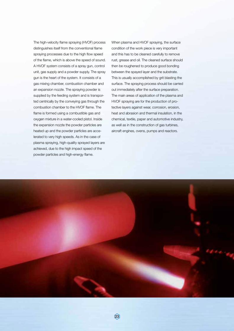
The high-velocity flame spraying (HVOF) process
distinguishes itself from the conventional flame
spraying processes due to the high flow speed
of the flame, which is above the speed of sound.
A HVOF system consists of a spray gun, control
unit, gas supply and a powder supply. The spray
gun is the heart of the system. It consists of a
gas mixing chamber, combustion chamber and
an expansion nozzle. The spraying powder is
supplied by the feeding system and is transpor-
ted centrically by the conveying gas through the
combustion chamber to the HVOF flame. The
flame is formed using a combustible gas and
oxygen mixture in a water-cooled pistol. Inside
the expansion nozzle the powder particles are
heated up and the powder particles are acce-
lerated to very high speeds. As in the case of
plasma spraying, high-quality sprayed layers are
achieved, due to the high impact speed of the
powder particles and high-energy flame.
When plasma and HVOF spraying, the surface
condition of the work piece is very important
and this has to be cleaned carefully to remove
rust, grease and oil. The cleaned surface should
then be roughened to produce good bonding
between the spayed layer and the substrate.
This is usually accomplished by grit blasting the
surface. The spraying process should be carried
out immediately after the surface preparation.
The main areas of application of the plasma and
HVOF spraying are for the production of pro-
tective layers against wear, corrosion, erosion,
heat and abrasion and thermal insulation, in the
chemical, textile, paper and automotive industry,
as well as in the construction of gas turbines,
aircraft engines, ovens, pumps and reactors.
1
3
1
2
24
Gas welding (Oxy-acethylene method)
The gas welding process is carried out with an
oxygen acetylene flame. The chemical compo-
sition of the weld metal and the properties of the
deposit are dependant on the composition of
the welding rod and the dilution with the base
material.
When gas welding with hardfacing, the low mel-
ting point of the hard alloys means that the base
material is not melted but only heated enough
to allow the hardfacing to melt and fuse with the
surface. The dilution with the base material is thus
negligibly small. It is usual to weld hard alloys with
a reducing flame, which means with an acetylene
gas surplus. With a neutral flame, a thick oxide
film would form, making welding difficult.
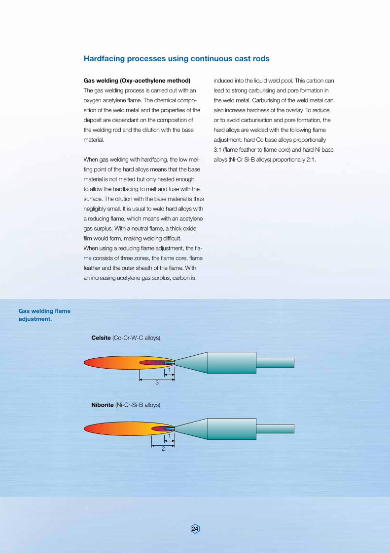
When using a reducing flame adjustment, the fla-
me consists of three zones, the flame core, flame
feather and the outer sheath of the flame. With
an increasing acetylene gas surplus, carbon is
induced into the liquid weld pool. This carbon can
lead to strong carburising and pore formation in
the weld metal. Carburising of the weld metal can
also increase hardness of the overlay. To reduce,
or to avoid carburisation and pore formation, the
hard alloys are welded with the following flame
adjustment: hard Co base alloys proportionally
3:1 (flame feather to flame core) and hard Ni base
alloys (Ni-Cr Si-B alloys) proportionally 2:1.
Hardfacing processes using continuous cast rods
Gas welding flame adjustment.
Celsite (Co-Cr-W-C alloys)
Niborite (Ni-Cr-Si-B alloys)
25
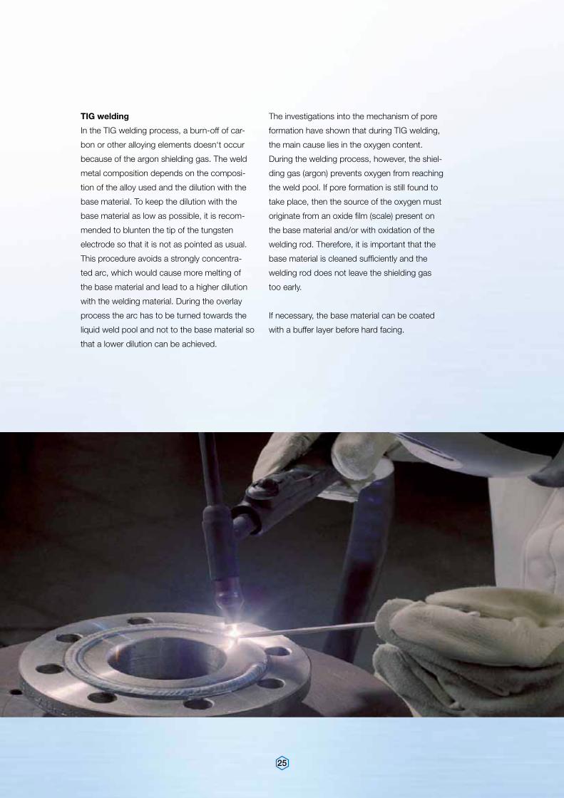
TIG welding
In the TIG welding process, a burn-off of car-
bon or other alloying elements doesn‘t occur
because of the argon shielding gas. The weld
metal composition depends on the composi-
tion of the alloy used and the dilution with the
base material. To keep the dilution with the
base material as low as possible, it is recom-
mended to blunten the tip of the tungsten
electrode so that it is not as pointed as usual.
This procedure avoids a strongly concentra-
ted arc, which would cause more melting of
the base material and lead to a higher dilution
with the welding material. During the overlay
process the arc has to be turned towards the
liquid weld pool and not to the base material so
that a lower dilution can be achieved.
The investigations into the mechanism of pore
formation have shown that during TIG welding,
the main cause lies in the oxygen content.
During the welding process, however, the shiel-
ding gas (argon) prevents oxygen from reaching
the weld pool. If pore formation is still found to
take place, then the source of the oxygen must
originate from an oxide film (scale) present on
the base material and/or with oxidation of the
welding rod. Therefore, it is important that the
base material is cleaned sufficiently and the
welding rod does not leave the shielding gas
too early.
If necessary, the base material can be coated
with a buffer layer before hard facing.
26
Quality management system – DIN EN ISO 9001:2008
Quality management system – ISO/TS 16949:2009 – Krefeld
Laboratory approval – DIN EN ISO/IEC 17025:2005
Approved welding consumable supplier in accordance with KTA 1408 – Nuclear applications –
Environmental management system – DIN EN ISO 14001:2004
Quality management
Our metal powders and continuous cast rods are
subjected to the most stringent quality control
measures. The chemical compositions are deter-
mined using modern equipment in our accredited
laboratory.
Standard equipment in our laboratories for the
determination of powder quality includes, sieve
analysis, flow property determination and the
determination of apparent and tap densities.
All of the powders produced fulfil at least the
minimum property requirements of the norms and
specifications.
Apart from the wide range of customer approvals,
the Deutsche Edelstahlwerke also boasts appro-
vals from the following independent organisations:
27
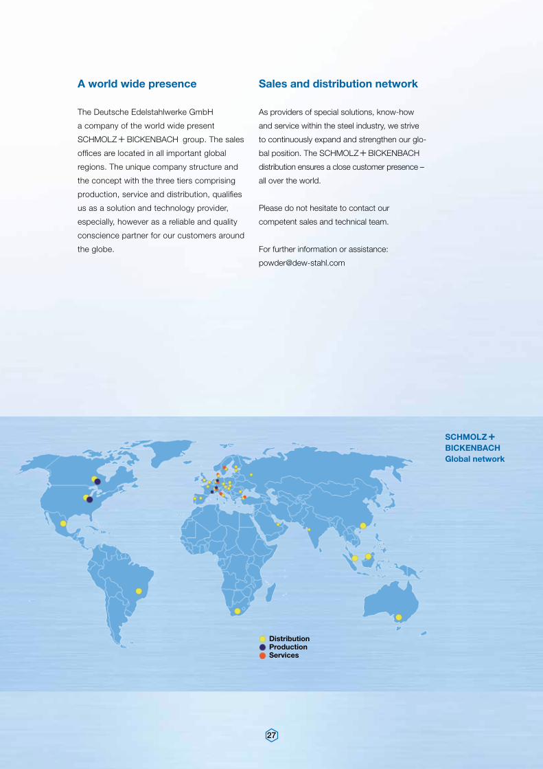
S+
BI Global network
A world wide presence Sales and distribution network
The Deutsche Edelstahlwerke GmbH
a company of the world wide present
s+bi group. The sales
offices are located in all important global
regions. The unique company structure and
the concept with the three tiers comprising
production, service and distribution, qualifies
us as a solution and technology provider,
especially, however as a reliable and quality
conscience partner for our customers around
the globe.
As providers of special solutions, know-how
and service within the steel industry, we strive
to continuously expand and strengthen our glo-
bal position. The s+bi
distribution ensures a close customer presence –
all over the world.
Please do not hesitate to contact our
competent sales and technical team.
For further information or assistance:
DistributionProductionServices
DEUTSCHE EDELSTAHLWERKE GMBH
Oberschlesienstr. 16 47807 Krefeld, Germany Phone +49 (0)2151 3633 – 2051Fax +49 (0)2151 3633 – [email protected]
General note (liability)
Information about the quality or usability of materials or products is for descriptive purposes
only. Confirmations in relation to the existence of certain characteristics or with reference to a
certain application always require a special written agreement. Printing errors, omissions and
changes excepted.
09.2
011,
100
0