Embed Size (px)
Citation preview

Evaluation of the allowable axial bearing capacity of a single pile subjected to machine vibration by numerical analysisIk Soo Ha1 and Jin‑Tae Han2*
BackgroundRecently, as the demand of plant constructions and extensions are increased, it is trend that the construction demands of the vibration machine foundation forming the basis of plant facilities are being increased. Due to the vertical and horizontal vibration load gen-erated on a vibration machine, the imbalance load is acted on the foundation Structure supporting the vibration machine and it causes the additional dynamic load.
In consideration of the dynamic load additionally generated, the design of the machine foundation is performed in the course of the following two steps. Firstly, calculate the natural frequency and displacement of the machine foundation system subjected to the vibration load by dynamic load to avoid resonance, and design to satisfy the allowable displacement given from the machine manufacturer. Next, the strength, stability and ground bearing capacity of the Machine foundation based on static load are evaluated, and in this case, the pseudo-static design considering the additional dynamic load is made up. In general, because the vibration machine foundation has very small ampli-tude, most of the studies have been performed with respect to the soil-spring-damper
Abstract
The purpose of this study is to analyze the changes in the vertical load of the pile when the additional vibration load due to mechanical vibration acted to the single pile supporting a vibration machine, and to review the validity of the typical calculation method for the axial bearing capacity of a single pile supporting the vibration machine by numerical analysis. Firstly, the 3D numerical model for the load–displacement behavior of a single pile was constituted. After the model was statically loaded to the allowable load in static analysis, the axial vibration due to machine vibration was added to the pile top in dynamic analysis. In these procedures, the static analysis was verified with the centrifuge test results for a single pile. Based on the analysis results, it was found that the additional dynamic load caused by machine vibration is about 6% of the allowable static load. It was thought that the design concepts of the machine foun‑dation, assuming that the additional dynamic load due to machine vibration equals to 50% of the static load in current code, is excessively conservative.
Keywords: Pile, Bearing capacity, Machine vibration, Numerical analysis, Centrifuge tests
Open Access
© The Author(s) 2016. This article is distributed under the terms of the Creative Commons Attribution 4.0 International License (http://creativecommons.org/licenses/by/4.0/), which permits unrestricted use, distribution, and reproduction in any medium, provided you give appropriate credit to the original author(s) and the source, provide a link to the Creative Commons license, and indicate if changes were made.
ORIGINAL RESEARCH
Ha and Han Geo-Engineering (2016) 7:22 DOI 10.1186/s40703-016-0036-5
*Correspondence: [email protected] 2 Dept. of Geotechnical Engineering, KICT (Korea Institute of Civil Engineering and Building Technology), Goyang, South KoreaFull list of author information is available at the end of the article
Page 2 of 12Ha and Han Geo-Engineering (2016) 7:22
model for evaluating the resonance phenomenon of the vibration machine by vibration load rather than the evaluation of the bearing capacity by vibration load [3, 7, 9, 10]. However, because the design criteria or theory that calculate the vertical and horizontal bearing capacity of the vibration Machine foundation by considering the dynamic load, were not clearly established until now, it is the real state that the construction has been performed by a conservative design method.
Arya et al. [1] have recommended so that the sum of static and dynamic loads is designed in less than 75% of the allowable bearing capacity when estimating the axial bearing capacity of a pile foundation, and if the machine manufacturer does not provide the information, they have also recommended so that the vertical directional equivalent dynamic force is designed by considering as 50% of the static load. In addition, in IS 2974 [4] which is the design criteria of the Reciprocating Motion machine foundation of Indian Standard Institution, it is defined that the ground stress below the foundation cannot exceed 80% of the allowable stresses under the static loading. In Korea, the above criteria become the basis in the calculation of the axial bearing capacity, however, due to conservative design practice although it is not the severe ground condition, in general, the allowable bearing capacity of the vibration machine foundation reduced to 50% of the allowable bearing capacity for the static load is calculated.
The purpose of this study is to analyze the changes in the vertical load of the pile when the additional vibration load due to mechanical vibration acted to the single pile sup-porting a vibration machine, and to review the validity of the typical calculation method for the axial bearing capacity of a single pile supporting the vibration machine by numer-ical analysis.
3D single pile numerical model and comparison with analytical solutionAnalysis condition
In recent years, the numerical studies for evaluating the behavior of machine vibration foundation have been conducted, but the design using the approximate analytical solu-tion [9] still has been made a lot in the practice. Novak set up a differential equation for single pile subjected to vertical vibration like Eq. 1, for the schematic diagram of single pile as shown in Fig. 1, and proposed the approximate analytical solution that can obtain the vertical response of single pile from the solution of differential equation.
Novak’s analytical solution may be easily applied in the practice with respect to the sim-ple model, but it is difficult to apply to complex ground condition and foundation sys-tem, and in particular, it is not possible to consider the load history condition. For this reason, the numerical methods are applied recently, but the procedure that the validity of numerical model is compared with the analytical solution under the simple condition is necessary.
In this study, the numerical model of 3D single pile applying the interface model which the interaction between pile-soil can be considered was created, and the model was compared with Novak’s analytic solution results.
(1)ω(z)[
−µω2+ iµω + G(Sω1 + iSω2)
]
− EpAd2ω(z)
dz2= 0

Page 3 of 12Ha and Han Geo-Engineering (2016) 7:22
Pile diameter ro is 0.3 m and pile length is 12 m, so the analysis was performed by the analytical method and the numerical analytical method for the circular concrete pile whose slenderness ratio l/ro is 40. When the vertical vibration was applied to the pile head, the maximum displacement of a pile generated by pile depth was calculated, and the results were compared. In the numerical analysis, the elastic model was applied as the soil model for the comparison with the analytical solution. For both analytical method and numerical method, 93, 280 and 460 m/sec were applied to the shear wave velocity Vs of the ground, respectively, and the behavior of the pile according to the soil stiffness was evaluated, and the load frequency ω was adjusted so that the non-dimen-sional frequency ao = roω/Vs became a constant value. Rayleigh Damping was applied to the attenuation of the ground in the numerical analysis, and the vertical vibration was simulated that apply the sinusoidal load (P = Po sin ωt,Po is 10 kN which is about 10% level of the static load) to the pile head.
In this study, FLAC3D Itasca Consulting Group Inc. [5] was used for the numerical model. Figure 2 shows the mesh of 3D numerical model of single pile and the size of the analysis area is 10 m × 10 m × 24 m (length × width × height). In order to reduce the
Fig. 1 Vertical pile and notation for analytic analysis

Page 4 of 12Ha and Han Geo-Engineering (2016) 7:22
analysis time by minimizing the number of elements, only one-quarter of the analysis model was modeled.
In order to consider the interaction between soil-pile, the bonded interface model was applied (Fig. 3). This model is defined by the linear Coulomb shear strength criterion such as shear force, vertical stiffness (kn), and shear stiffness (ks), tensile strength (Ts) and shear strength (Ss) that act to interface nodal point. The condition of analytic solution is Rigid attachment condition, so in order to compare the numerical analytical solution with the same condition, kn, ks, Ts, Ss carried out the numerical analysis by setting unre-alistic very large value.
Fig. 2 3D numerical analysis mesh for single pile system (1/r0 = 40)
Fig. 3 Constituents of bonded interface model

Page 5 of 12Ha and Han Geo-Engineering (2016) 7:22
In the boundary condition, the quiet-boundary condition [11] was applied to prevent the reflection from the boundary. This method is completely effective for absorbing the body wave approaching to the boundary at larger angles of incidence than 30°, or absorbs energy at low incident angle, but it is not perfect. However, this technique has the advantage operating at the time domain, and the effect was demonstrated in both models of the finite element method and the finite difference method [8]. The quiet-boundary scheme involves dashpots attached independently to the boundary in the nor-mal and shear directions. The dashpots provide viscous normal and shear traction given by
where vn and vs are the normal and shear components of the velocity at the boundary; ρ is the mass density; and Cp and Cs are the p- and s-wave velocities.
Validity review of numerical model
Figure 4 shows the maximum displacement by the pile depth of the approximate analytic solution and the numerical solution when the vertical vibration was applied to the pile head. In the case of the analytical solution, because the maximum displacement by the depth of the case that the maximum displacement amplitude at the pile head is ‘1’ is rep-resented, in order to compare the numerical analysis solution with this value, two results were compared each other by the normalized method dividing the maximum displace-ment calculated from the pile head into the maximum displacement by each depth. As shown in Fig. 4, the approximate solution and the numerical solution show almost simi-lar pile displacement patterns even if the soil stiffness is changed, so it could be identi-fied that the created numerical model has the minimum validity.
(2)tn = −ρCpvn
ts = −ρCsvs
Fig. 4 Max. pile displacement with depth calculated by analytical solution and numerical analysis (1/r0 = 40, a0 = 0.3) a Vs/Vc = 0.01, bVs/Vc = 0.03, c Vs/Vc = 0.05

Page 6 of 12Ha and Han Geo-Engineering (2016) 7:22
Determination of characteristic value for soil‑pile interfaceIn this study, one pile of the group piles targeting the machine foundation in currently operation was modeled as a centrifuge test, and the vertical ultimate bearing capacity of single pile from the load–displacement curve of a pile head obtained from the static pile load tests for the model, was calculated. The load–displacement curve from the cen-trifugal model test was simulated by numerical analysis verified from the comparison with the analytical solution, and the interface characteristic value between soil-pile was determined.
A single pile of the group piles was simulated as an analysis object targeting the foun-dation (see Fig. 5) of LNG power plant currently being operated, and have modeled it by the centrifuge model test. The specifications of the analysis object pile are in the Table 1.
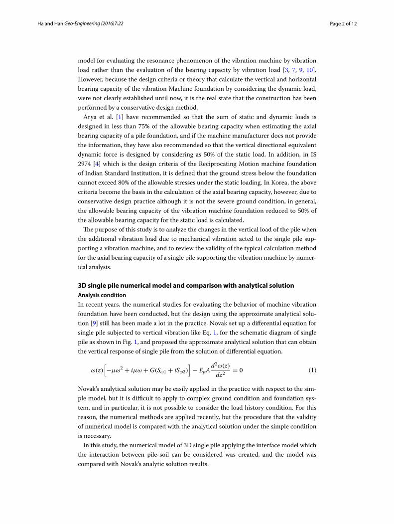
Figure 6 shows the centrifuge facility in KAIST whose radius is 5 m, the model pile and measuring instruments. Static load test for the model pile in the centrifuge facility was performed and load-settlement curve was obtained. Figure 7 shows the results of the
Fig. 5 Selection of the target single pile
Table 1 Specifications of the analysis model pile
Pile type Diameter (mm)
Length (m) Unit weight (kN/m3)
Elastic modulus (MN/m2)
Poisson ratio
Cast‑in situ concrete pile 1000 15 24.5 29,580 0.2
Fig. 6 Centrifuge tests for the pile. a 5 m radius centrifuge in KAIST, b model pile and measuring instruments
Page 7 of 12Ha and Han Geo-Engineering (2016) 7:22
static pile load test by the static loading (displacement control method) from the centri-fuge test. As the test results of single pile, the numerical model was applied and simulated, and the interface constants ks of pile-ground were estimated from the repeated analysis.
In the numerical analysis, the load control method is the same displacement control method as the experiments, and the 0.05 mm/sec as the experiment was applied as a load-ing rate. The foundation shape and the input properties in the numerical analysis were applied by converting the foundation shape and properties applied to the model in the centrifugal model test into a prototype. The damping ratio of the ground applied in the numerical analysis was 5%, and the Mohr–Coulomb model, was applied as a soil model.
Table 2 shows the basic properties for the numerical analysis. From the centrifuge test for shallow foundation on silica sand, the load-settlement curve was obtained and the elastic modulus in Table 2 were calculated through iterative numerical analysis in order to simulate the load-settlement curve from the test. Friction angle corresponding to the relative density of 75% was obtained from the relation between the friction angle and relative density through triaxial compression tests varying relative density of silica sand.
Fig. 7 Static load test result by centrifugal test and numerical analysis results
Table 2 Basic soil properties for numerical analysis
Soil types Unit weight (kN/m3)
Elastic modulus (MN/m2)
Poisson ratio Friction angle (degree)
Cohesion (kN/m2)
Silica sand 15.2 90 0.25 41 0

Page 8 of 12Ha and Han Geo-Engineering (2016) 7:22
Figure 7 also shows the results simulating the test results. From Fig. 7, as a result of repetitive numerical analysis, the interface constant ks of ground-pile was determined as 10 MPa/m because it showed that the most appropriately simulate the experimental result. Figure 8 shows the pile installation layout and the mesh for numerical analysis simulating single pile centrifuge tests results.
Review of calculation method of axial bearing capacity of vibration machine foundationIn the method obtaining the ultimate bearing capacity from load-settlement curve of single pile obtained from the centrifuge test, the load at the settlement corresponding to 10% of the pile diameter was calculated as the ultimate bearing capacity by applying British Standard BSI [2].
Fig. 8 Numerical analysis mesh for simuating single pile centrifuge tests results
Page 9 of 12Ha and Han Geo-Engineering (2016) 7:22
The ultimate load Qu of single pile was calculated to 6.3 MN from Fig. 7.In the 3D numerical model that simulates the experimental results of single pile foun-
dation, 2.1 MN, which is one-third of 6.3 MN, was considered as the working load. First, this working load 2.1 MN was loaded, and the additional mechanical vibration was applied to this working load, and consequently, the dynamic additional load that may be generated by the mechanical vibration was calculated.
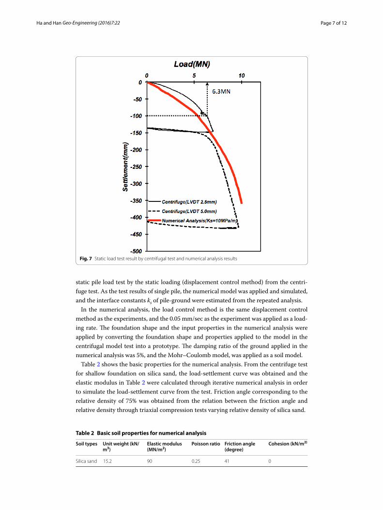
The additional impact by the mechanical vibration in the working load condition was analyzed by the method loading the vibration displacement. The rotating speed of the target vibration machine is 1500 rpm, so the frequency is equivalent to 25 Hz. In Korean Design Criteria, the allowable displacement width of the foundation for the high-speed rotary machine foundation is specified as maximum 0.06 mm. Based on these criteria, in this study, the load condition of the pile subjected to the working load of 2.1 MN to the foundation was simulated. In order to estimate the dynamic load additionally gener-ated caused by the mechanical vibration in the static equilibrium subjected to the work-ing load, the dynamic numerical analysis that applies the vibration displacement time history of the maximum amplitude (0.06 mm) that can be generated (allowable) on the characteristic of the applicable machine foundation to the pile head, was performed. The response additional load time history at the pile head was obtained from this dynamic numerical analysis results, and the additional dynamic load applied to the pile head by the mechanical vibration, was estimated.
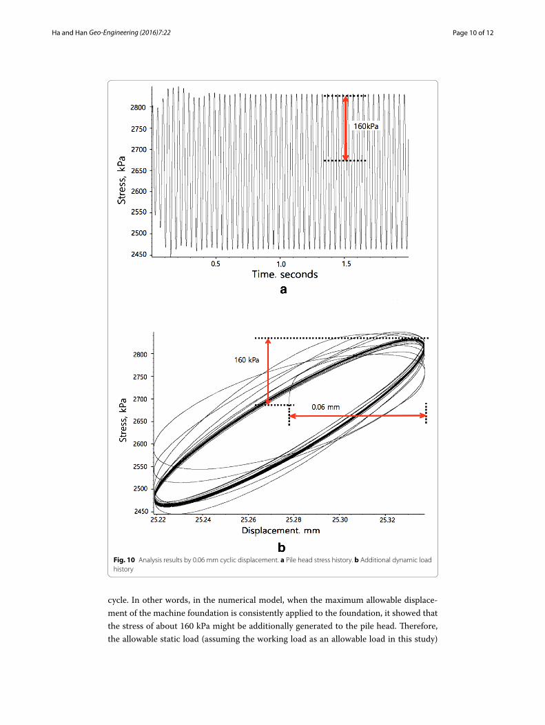
Figure 9 shows the displacement (0.06 mm) time history of the pile head, which is additionally loaded according to the mechanical vibration in the working load state, and Fig. 10a shows the additional stress time history that is induced to the pile head. Fig-ure 10b shows the load changes of the pile head according to the vibration time that is additionally generated for the vibration displacement in addition to the working load. As shown in Fig. 10b, the stress at the pile head showed almost constant value after a certain
Fig. 9 Displacement time history (max. amp. 0.06 mm) in the service load condition
Page 10 of 12Ha and Han Geo-Engineering (2016) 7:22
cycle. In other words, in the numerical model, when the maximum allowable displace-ment of the machine foundation is consistently applied to the foundation, it showed that the stress of about 160 kPa might be additionally generated to the pile head. Therefore, the allowable static load (assuming the working load as an allowable load in this study)
Fig. 10 Analysis results by 0.06 mm cyclic displacement. a Pile head stress history. b Additional dynamic load history
Page 11 of 12Ha and Han Geo-Engineering (2016) 7:22
was 2.1 MN, and it was evaluated that additional dynamic load generated by mechanical vibration is 125.7 kN.
In the design criteria for structure foundation, the allowable bearing capacity of single pile supporting machine foundation should be 1/2 of the static allowable bearing capac-ity [6]. This means that additional dynamic load by mechanical vibration can be gener-ated up to 100% of the static load. In addition, these criteria are supposed to be applied only under severe dynamic condition and there are not criteria for other dynamic and soil conditions. Therefore, these criteria are uniformly applied irrespective of the dynamic conditions and over conservative values are calculated in practice.
It was identified that considering the analysis results in this study, only 125.7 kN cor-responding to 6% of the allowable static load in the dynamic load generated by mechani-cal vibration in the allowable static load state, is generated in addition. Of course, the numerical model is the modeling of sandy soil ground without groundwater and the characteristic value is also obtained under limited condition. Nevertheless, these results show that the practice that calculates the allowable bearing capacity of the pile support-ing the vibrating machine by applying the current design criteria may be excessively con-servative and uneconomical designs.
ConclusionsIn this study, in order to examine the validity of the calculation method of the axial bear-ing capacity of a single pile supporting the vibration machine that is applying in conven-tional practice, 3D dynamic numerical analysis was performed.
As a pre-procedure for evaluating the effects of mechanical vibration applied to the single pile, it was confirmed that the numerical model has the validity through the com-parison with the analytical solution in simple condition. Then, the load–displacement curve of a pile head and the axial ultimate bearing capacity were obtained from the cen-trifuge tests for the numerical analysis. The load–displacement curve from the test was simulated by performing the repeated numerical analysis using the numerical model, and the characteristic value for interface between soil-pile was determined.
The allowable bearing capacity of a pile calculated by the model tests was considered as a working load, and after loading the working load to the single pile by the numeri-cal analysis, the dynamic numerical analysis that applies the vibration of the machine foundation was performed. As a result of the numerical analysis, it could be confirmed that because the additional dynamic load applied by vibration was 6% of the allowable static load, current design criteria that the additional dynamic load applied by mechani-cal vibration has considered as 50% of static load, is very conservative and uneconomical design.Author details1 Dept. of Civil Engineering, Kyungnam University, Changwon, South Korea. 2 Dept. of Geotechnical Engineering, KICT (Korea Institute of Civil Engineering and Building Technology), Goyang, South Korea.
AcknowledgementsThis research was supported by The Korea Institute of Construction and Building Technology.
Received: 7 June 2016 Accepted: 23 November 2016
Page 12 of 12Ha and Han Geo-Engineering (2016) 7:22
References 1. Arya SC, O’Neill MW, Pincus G (1984) Design of structures and foundations for vibrating machines. Gulf Publishing
Company, Houston 2. British Standard Institute, Concrete—Complementary British Standard to BS EN 206‑1‑Part 1: Method of specifying
and guidance for the specifier, BSI, 2006 3. El Naggar MH, Novak M (1994) Non‑linear model for dynamic axial pile response. J Geotech Eng 120(2):308–329 4. Indian Standard Institution(ISI). Indian standard code of practice for design and construction of machine foundation
IS 2974, Part I, New Delhi, India, 1970 5. Itasca Consulting Group, Inc. FLAC—fast lagrangian analysis of continua. Version 3.1, Minnesota, USA, 2008 6. Korea ministry of land, transport and maritime affairs (MLTM). Design criteria for structure foundation, 2008; 97–101 7. Kuhlemeyer RL (1979) Vertical vibration of piles. J Geotech Eng Div 105(GT2):273–287 8. Kunar RR, Beresford PJ, Cundall PA (1977) A tested soil‑structure model for surface structures. Proc Symp Soil Struct
Interact 1(1):137–144 9. Novak M (1977) Vertical vibration of floating piles. J Eng Mech Div 103(EM1):153–168 10. Novak M, El Sharnouby B (1983) Stiffness and damping constants of single piles. J Eng Mech Div 109(GT7):961–974 11. Lysmer J, Kuhlemeyer RL (1969) Finite dynamic model for infinite media. J Eng Mech. 95(EM4):859–877