Embed Size (px)
Citation preview
1
Evaluation of Wire Harnesses Recently Removed from F-16
Aircraft
Dr. William G. Linzey, Mr. Michael G. Traskos, Dr. Armin M. Bruning
Lectromechanical Design Company
45,000 Underwood Lane
Sterling, Virginia 20166
Phone: (703) 481 – 1233
Fax: (703) 481 – 1238
Mr. John Ashour
InterConnect Wiring LP
5024 W Vickery Blvd
Fort Worth, Texas 76107
Phone: (817) 377 – 9473
Fax: (817) 732 – 8667
Email: [email protected]
Abstract
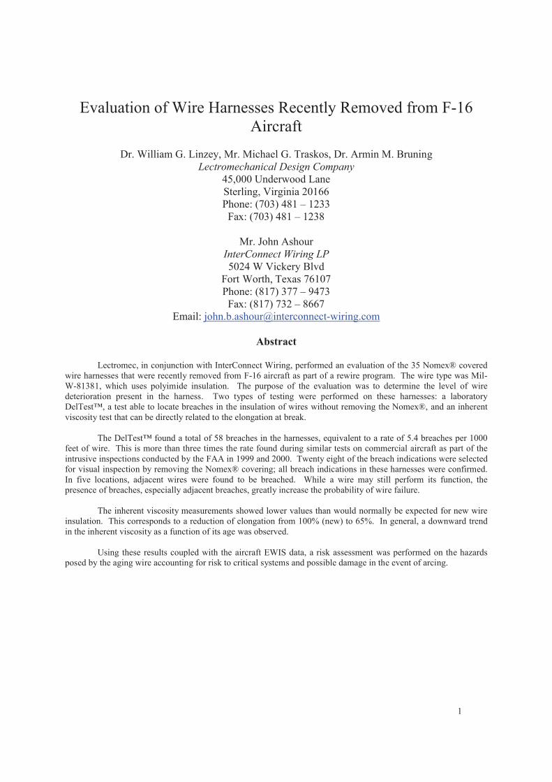
Lectromec, in conjunction with InterConnect Wiring, performed an evaluation of the 35 Nomex® covered
wire harnesses that were recently removed from F-16 aircraft as part of a rewire program. The wire type was Mil-
W-81381, which uses polyimide insulation. The purpose of the evaluation was to determine the level of wire
deterioration present in the harness. Two types of testing were performed on these harnesses: a laboratory
DelTest™, a test able to locate breaches in the insulation of wires without removing the Nomex®, and an inherent
viscosity test that can be directly related to the elongation at break.
The DelTest™ found a total of 58 breaches in the harnesses, equivalent to a rate of 5.4 breaches per 1000
feet of wire. This is more than three times the rate found during similar tests on commercial aircraft as part of the
intrusive inspections conducted by the FAA in 1999 and 2000. Twenty eight of the breach indications were selected
for visual inspection by removing the Nomex® covering; all breach indications in these harnesses were confirmed.
In five locations, adjacent wires were found to be breached. While a wire may still perform its function, the
presence of breaches, especially adjacent breaches, greatly increase the probability of wire failure.
The inherent viscosity measurements showed lower values than would normally be expected for new wire
insulation. This corresponds to a reduction of elongation from 100% (new) to 65%. In general, a downward trend
in the inherent viscosity as a function of its age was observed.
Using these results coupled with the aircraft EWIS data, a risk assessment was performed on the hazards
posed by the aging wire accounting for risk to critical systems and possible damage in the event of arcing.
2
1. Introduction
As an aircraft ages, the integrity of the Electrical Wire Interconnect System (EWIS) can become
compromised. This can lead to aircraft system malfunctions and in some cases, arcing, which can result in more
significant damage. When the insulating material is operating normally, electrical current carrying conductors are
protected by a thin layer of insulating material. However, when there is a breach in this insulating material, contact
with grounded structure or foreign fluids can result in electrical arcing flashovers. Polyimide insulation is
susceptible to environmental deterioration due to hydrolysis that can reduce the polymer’s molecular weight. The
degradation of the insulation can lead to a greater susceptibility of breaches.
Lectromec performed a series of tests to evaluate the number of insulation breaches and the chemical
degradation of 35 electrical wire harnesses that were removed from F-16 aircraft by InterConnect Wiring during a
wire replacement program. There were two types of testing performed on the wire harnesses: a laboratory
DelTest™ (breach detection) and an inherent viscosity test (chemical degradation test).
The laboratory DelTest™ detects breaches in the wire insulation that reach the conductor. It is a snapshot
of the condition of the harness on the day it was removed from the airplane. Lectromec performed a DelTest™ on
all wires from each of the 35 harnesses taken from the F-16. The DelTest™ process tests wires to within 1-3 inch of
the connector back shell by submerging the harness in a bath with the connectors held above the water surface. The
DelTest™ was done without removing the Nomex® braid. The results indicated 58 insulation breaches in the over
1500 wires tested; this corresponded to a rate of 5.4 breaches per 1000 feet of wire. On a representative number of
DelTest™ failure indications, Lectromec located the breach, removed the Nomex® braid and photographed a
number of insulation breaches. In five cases, breaches in adjacent wires were found.
The inherent viscosity test is a measure of the molecular weight of the polyimide tape that is the primary
insulation of the wire. The molecular weight can be related to the elongation at break and other physical
characteristics of the film. Lectromec sampled wires from eleven locations of the harnesses and performed 29
measurements. The inherent viscosity test requires a small sample of the polyimide tape of wire (~6 inches) and is a
destructive. In general, the inherent viscosity was lower than would be expected for new wire.
These results are for the harnesses of one aircraft so they cannot be generally applied to this fleet of
aircraft. However, the results do indicate a reduction of the integrity of the harnesses, which is at least in part due to
environmental aging. If this result is representative of the fleet, than the problem with the harnesses would have
continued and harness replacement should improve the system reliability. Further testing would be needed to
validate that assessment.
After the testing was complete it was decided to take this opportunity to develop a procedure for risk
assessment of the harnesses with the goal of setting priorities for the replacement of the F-16 harnesses. It was
based on the probability for harness failure and the effect on aircraft level system of those failures. Because of
limited resources and time, only three harnesses that were found to have multiple breaches were evaluated using the
limit data available. The results indicate that, if developed further, this type of risk assessment could be useful when
prioritizing harness replacement.
2. Wire Replacement Program
Falcon Dynamics, a joint venture company of InterConnect Wiring and Aerospace and Commercial
Technology (ACT), designed the Falcon Wire program to meet the needs of the world-wide F-16 fleet. The Falcon
Wire program replaces the wiring harnesses that over the years have been the most troublesome and had the most
incidences of electrical problems. The wiring harnesses being replaced were originally made with polyimide
(Kapton ®) insulated wiring. The replacement wiring harnesses are made with TKT insulation. The replacement
wiring harnesses are a one-for-one substitution. The only difference is in the insulation of the wires.
The Falcon Wire program is a nine step process: (1) Determine configuration of aircraft, (2) Assemble
replacement wiring harnesses, (3) Procure installation hardware and tools, (4) Remove panels and equipment from
3
aircraft, (5) Remove old wiring harnesses, (6) Install new wiring harnesses, (7) Reinstall panels and equipment, (8)
Perform operational checks, and (9) Perform Functional Check Flight (FCF).
Most of the wiring harnesses being replaced are located in the following locations: mid fuselage, aft
fuselage, engine bay, Flaperon bay, and wheel wells. The Falcon Wire program can be expanded to include more
areas such as: wings, fuel cell areas, cockpit, forward fuselage, panel wiring harnesses, or the whole aircraft. A
customer can pick and choose what areas they want replaced.
Over 4,500 F-16’s have been made to date. Many of them are more than 20 years old. Over the years
wiring harnesses start to experience problems due environmental conditions and aging. The Falcon Wire program
solves those problems. The remainder of this report documents the problems discovered on one ship set of wiring
harnesses that were removed from an F-16. Up to this point, the severity of the number of problems was unknown.
Falcon Dynamics requested that Lectromec do an analysis and answer the following questions: (1) How many
breaches of insulation per foot of wire were found in the removed wiring harnesses? (2) How much did the
polyimide insulation age (or deteriorate) over the course of the aircraft’s life?
The removed wiring harnesses came from an F-16 A model. The aircraft was 24 years old. Of the 24
years, it spent 5.5 years in the airplane graveyard at AMARC (Aircraft Maintenance And Regeneration Center).
Later it was resurrected and sold to a Foreign Military Sales (FMS) country where it now resides.
2. Test Procedure
The harnesses were removed from the F-16 and shipped to Lectromec for testing. The DelTest™ was
performed first on all harnesses. Selected samples of wire insulation were then removed from the harnesses and the
inherent viscosity of these samples was measured.
A. DelTest™
To perform the DelTest™, the harness was placed in a water bath with the harness connectors suspended
1-3 inches above the water. The harness was allowed to soak a preset time. A test voltage was then applied to each
of the wires conductors and the leak current monitored using a collection electrode in the water bath.
On seven of the harnesses, the locations of the breaches within the harness were found by reintroducing the
harnesses to the water bath slowly while monitoring the leakage current. The breaches were normally located to
within 6 inches. Before the Nomex® was removed, it was inspected for damage which would indicate external
trauma that may have caused the breach. The Nomex® was then carefully removed and the breaches were located
visually.
B. Inherent ViscosityThe inherent viscosity was measured for specimens selected from 29 wires from 11 different harnesses. In
this test a piece of polyimide tape at least 6” long was used for each test. The specimen was dissolved in a
concentrated solution of sulfuric acid and then filtered. A viscosity measurement is the performed on the solution.
A second viscosity measurement is made on a pure sulfuric acid solution. The inherent viscosity is calculated using
the equation
c
t
t
inh
0
log
Where, t and to are the respective times for the solution with and without polymer to go between two lines in a
viscometer, and c is the concentration of dissolved polymer. More details of the inherent viscosity procedure are
found in reference*.
* Turner, N. H., LaCourt, P. R. Chemical Manufacturer’s Test Applied to Aged Aircraft MIL-W-81381 Type Wire
Insulation, Presented at the 2003 Aging Aircraft Conference.
4
3. Results
A. DelTest™
The results of the DelTest™ are shown by the harnesses tested in Table 1. There were 58 breach
indications found in the 1565 wires and 10,781 feet of wire tested. This corresponds to a rate of about 4 breaches
per 100 wires or 5.4 breaches per 1000 feet. Those wires that indicated breaches were double-checked by matching
the leak current at both termination points. Wires that indicated a breach that contained splices were removed, as the
test could not verify if the wire or splice leaked. Leakage currents from cable shields are not reported in the results
below.
Table 1: DelTest™ results for 35 harnesses
Harness
IDZones
Last
Modified
Wire
Breaches# Wires # Feet
Breaches
per 1000'
651-23 Center Fuselage 1/1/1982 0 71 408.5 0.0
652-23 Center Fuselage 1/1/1982 1 69 600.9 1.7
653-23 Center Fuselage 1/1/1982 1 61 443.5 2.3
654-21 Center Fuselage 1/1/1982 0 61 405.5 0.0
656-01 Center Fuselage 1/1/1982 1 39 106.2 9.4
657-02 Center Fuselage 1/1/1982 0 21 29.0 0.0
661-22 Nose Landing Gear 1/1/1982 0 47 497.3 0.0
663-21 Center Fuselage 1/1/1982 1 53 233.0 4.3
668-529 Center Fuselage 12/6/1991 3 111 1028.8 2.9
669-23 Center Fuselage 1/1/1982 4 45 329.7 12.1
677-26 Nose Landing Gear 12/6/1991 2 51 467.7 4.3
678-30 Nose Landing Gear 1/1/1982 1 58 617.5 1.6
681-26 Center Fuselage 1/1/1982 0 13 107.4 0.0
683-22 Center Fuselage 1/1/1982 0 10 60.8 0.0
684-22 Center Fuselage 1/1/1982 0 10 27.8 0.0
685-21 Nose Landing Gear 1/1/1982 1 4 34.8 28.7
692-20 Nose Landing Gear 1/1/1982 0 26 79.5 0.0
693-21 Nose Landing Gear 1/1/1982 2 12 33.0 60.6
695-21 MLG Wheel Well 1/1/1982 2 2 15.8 126.3
696-21 MLG Wheel Well 1/1/1982 2 2 17.5 114.3
698-502 Aerial Refueling Cavity 12/6/1991 2 69 257.5 7.8
735-20 Flaperon Bay 1/1/1982 0 6 21.0 0.0
736-24 Flaperon Bay 3/12/1983 5 30 90.3 55.4
781-502 Aft Fuselage Engine 1/8/2003 3 15 20.0 150.0
782-512 Aft Fuselage Engine 1/8/2003 4 58 230.1 17.4
783-601 Aft Fuselage Engine 1/8/2003 0 63 381.2 0.0
784-604 Aft Fuselage Engine 12/26/1991 1 51 386.8 2.6
1523-01 Center Fuselage 1/1/1982 0 35 151.2 0.0
2601-16 MLG Wheel Well 9/8/1983 8 134 1491.7 5.4
2603-04 Center Fuselage 9/8/1983 6 39 339.3 17.7
2604-502 MLG Wheel Well 12/26/1991 4 41 447.2 8.9
2606-07 Center Fuselage 3/4/1985 2 34 227.9 8.8
2609-521 Center Fuselage 12/26/1991 0 132 705.3 0.0
2610-502 Center Fuselage 3/4/1985 1 31 349.8 2.9
2713-507 Center Fuselage 1/8/2003 1 61 138.5 7.2
58 1565.0 10781.8 5.4Total
These failure rates are based upon the cut lengths for the wires supplied to Lectromec by Interconnect. In
practice, the actual length of the wires maybe slightly shorter, which would increase the failure rate reported.
5
Table 2. Harnesses selected for further investigation
Harness ID
595-21
652-23
677-26
696-21
781-502
2601-16
2603-04
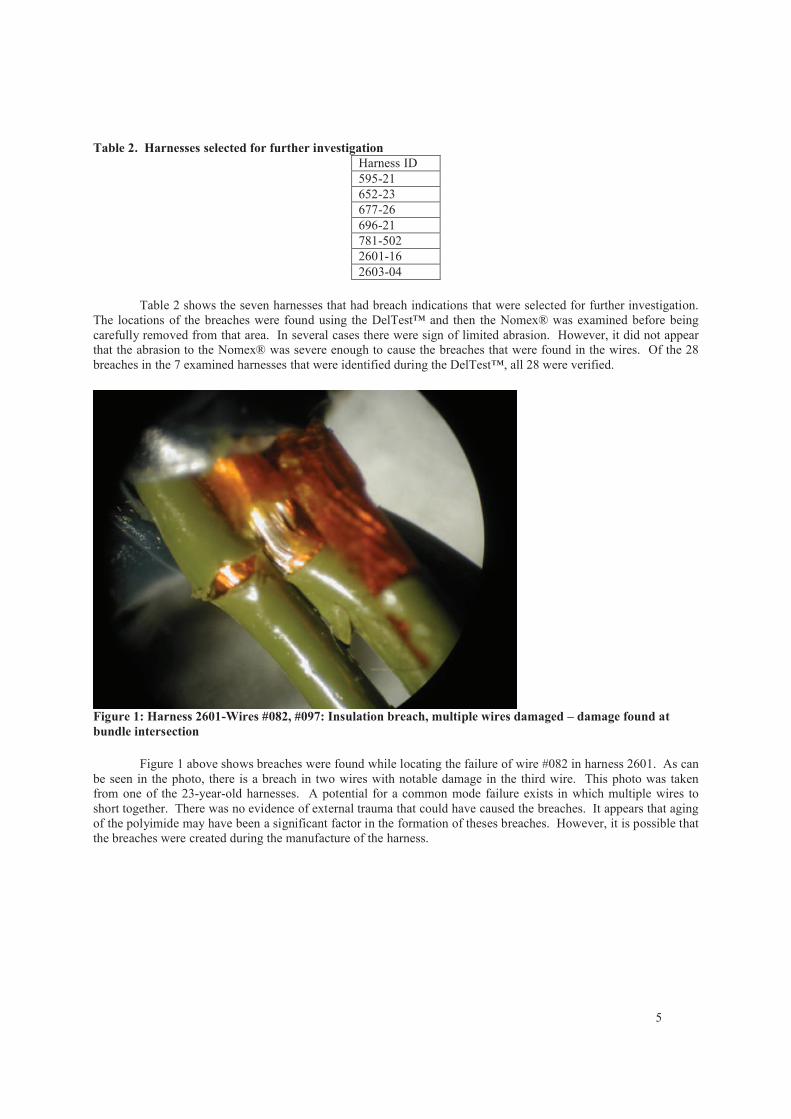
Table 2 shows the seven harnesses that had breach indications that were selected for further investigation.
The locations of the breaches were found using the DelTest™ and then the Nomex® was examined before being
carefully removed from that area. In several cases there were sign of limited abrasion. However, it did not appear
that the abrasion to the Nomex® was severe enough to cause the breaches that were found in the wires. Of the 28
breaches in the 7 examined harnesses that were identified during the DelTest™, all 28 were verified.
Figure 1: Harness 2601-Wires #082, #097: Insulation breach, multiple wires damaged – damage found at
bundle intersection
Figure 1 above shows breaches were found while locating the failure of wire #082 in harness 2601. As can
be seen in the photo, there is a breach in two wires with notable damage in the third wire. This photo was taken
from one of the 23-year-old harnesses. A potential for a common mode failure exists in which multiple wires to
short together. There was no evidence of external trauma that could have caused the breaches. It appears that aging
of the polyimide may have been a significant factor in the formation of theses breaches. However, it is possible that
the breaches were created during the manufacture of the harness.
6
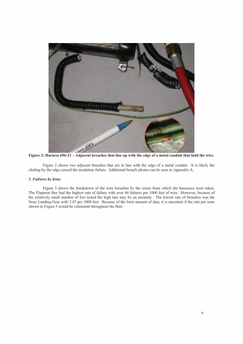
Figure 2: Harness 696-21 – Adjacent breaches that line up with the edge of a metal conduit that held the wire.
Figure 2 shows two adjacent breaches that are in line with the edge of a metal conduit. It is likely the
chafing by the edge caused the insulation failure. Additional breach photos can be seen in Appendix A.
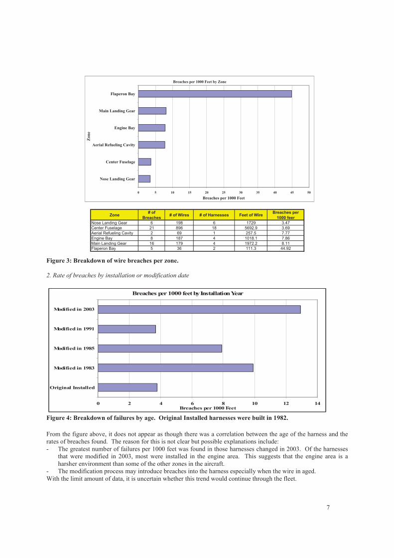
1. Failures by Zone
Figure 3 shows the breakdown of the wire breaches by the zones from which the harnesses were taken.
The Flaperon Bay had the highest rate of failure with over 44 failures per 1000 feet of wire. However, because of
the relatively small number of feet tested the high rate may be an anomaly. The lowest rate of breaches was the
Nose Landing Gear with 3.47 per 1000 feet. Because of the limit amount of data, it is uncertain if the rate per zone
shown in Figure 3 would be consistent throughout the fleet.
7
Zone# of
Breaches# of Wires # of Harnesses Feet of Wire
Breaches per
1000 feer
Nose Landing Gear 6 198 6 1729 3.47
Center Fuselage 21 896 18 5692.9 3.69
Aerial Refueling Cavity 2 69 1 257.5 7.77
Engine Bay 8 187 4 1018.1 7.86
Main Landing Gear 16 179 4 1972.2 8.11
Flaperon Bay 5 36 2 111.3 44.92
Breaches per 1000 Feet by Zone
0 5 10 15 20 25 30 35 40 45 50
Nose Landing Gear
Center Fuselage
Aerial Refueling Cavity
Engine Bay
Main Landing Gear
Flaperon Bay
Zon
e
Breaches per 1000 Feet
Figure 3: Breakdown of wire breaches per zone.
2. Rate of breaches by installation or modification date
Breaches per 1000 feet by Installation Year
0 2 4 6 8 10 12 14
Original Installed
Modified in 1983
Modified in 1985
Modified in 1991
Modified in 2003
Breaches per 1000 Feet
Figure 4: Breakdown of failures by age. Original Installed harnesses were built in 1982.
From the figure above, it does not appear as though there was a correlation between the age of the harness and the
rates of breaches found. The reason for this is not clear but possible explanations include:
- The greatest number of failures per 1000 feet was found in those harnesses changed in 2003. Of the harnesses
that were modified in 2003, most were installed in the engine area. This suggests that the engine area is a
harsher environment than some of the other zones in the aircraft.
- The modification process may introduce breaches into the harness especially when the wire in aged.
With the limit amount of data, it is uncertain whether this trend would continue through the fleet.
8
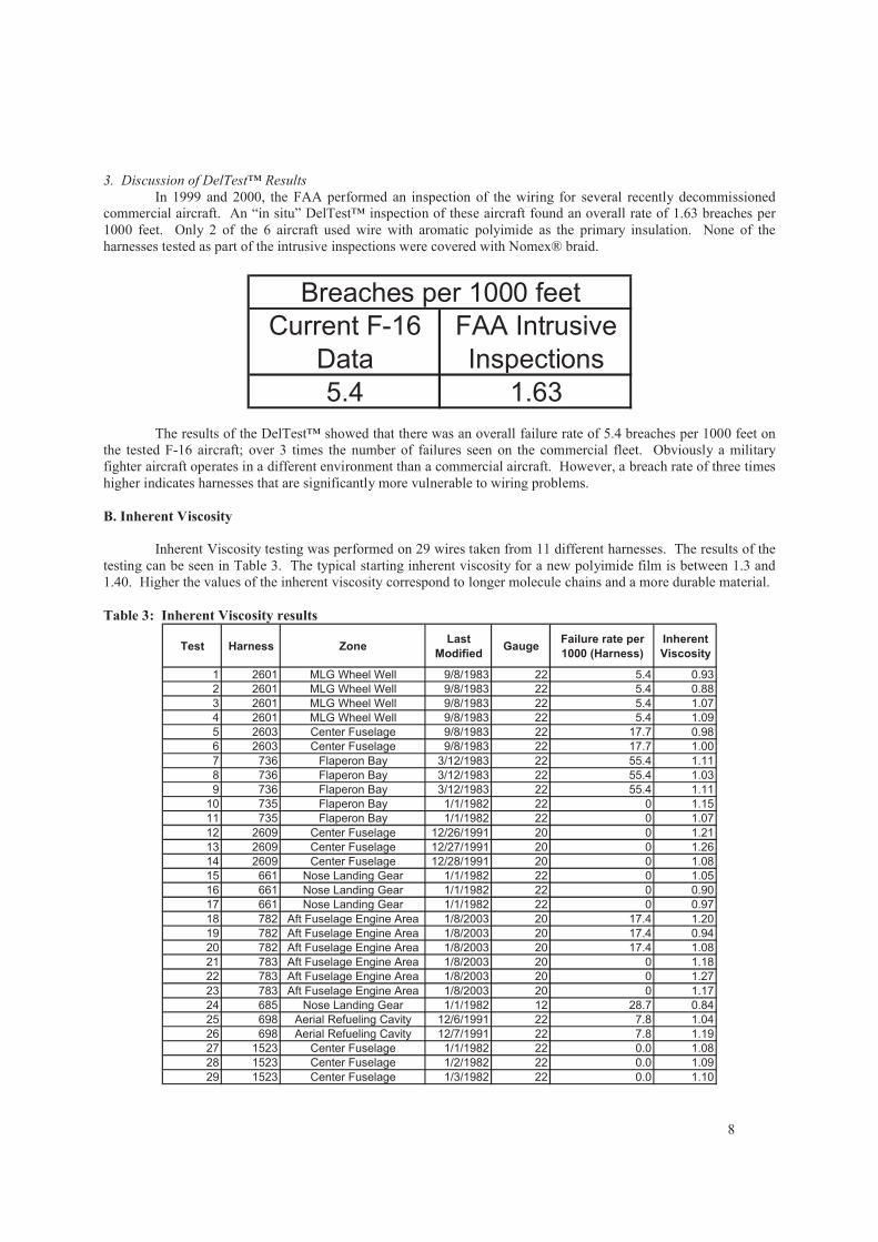
3. Discussion of DelTest™ Results
In 1999 and 2000, the FAA performed an inspection of the wiring for several recently decommissioned
commercial aircraft. An “in situ” DelTest™ inspection of these aircraft found an overall rate of 1.63 breaches per
1000 feet. Only 2 of the 6 aircraft used wire with aromatic polyimide as the primary insulation. None of the
harnesses tested as part of the intrusive inspections were covered with Nomex® braid.
Current F-16
Data
FAA Intrusive
Inspections
5.4 1.63
Breaches per 1000 feet
The results of the DelTest™ showed that there was an overall failure rate of 5.4 breaches per 1000 feet on
the tested F-16 aircraft; over 3 times the number of failures seen on the commercial fleet. Obviously a military
fighter aircraft operates in a different environment than a commercial aircraft. However, a breach rate of three times
higher indicates harnesses that are significantly more vulnerable to wiring problems.
B. Inherent Viscosity
Inherent Viscosity testing was performed on 29 wires taken from 11 different harnesses. The results of the
testing can be seen in Table 3. The typical starting inherent viscosity for a new polyimide film is between 1.3 and
1.40. Higher the values of the inherent viscosity correspond to longer molecule chains and a more durable material.
Table 3: Inherent Viscosity results
Test Harness ZoneLast
ModifiedGauge
Failure rate per
1000 (Harness)
Inherent
Viscosity
1 2601 MLG Wheel Well 9/8/1983 22 5.4 0.93
2 2601 MLG Wheel Well 9/8/1983 22 5.4 0.88
3 2601 MLG Wheel Well 9/8/1983 22 5.4 1.07
4 2601 MLG Wheel Well 9/8/1983 22 5.4 1.09
5 2603 Center Fuselage 9/8/1983 22 17.7 0.98
6 2603 Center Fuselage 9/8/1983 22 17.7 1.00
7 736 Flaperon Bay 3/12/1983 22 55.4 1.11
8 736 Flaperon Bay 3/12/1983 22 55.4 1.03
9 736 Flaperon Bay 3/12/1983 22 55.4 1.11
10 735 Flaperon Bay 1/1/1982 22 0 1.15
11 735 Flaperon Bay 1/1/1982 22 0 1.07
12 2609 Center Fuselage 12/26/1991 20 0 1.21
13 2609 Center Fuselage 12/27/1991 20 0 1.26
14 2609 Center Fuselage 12/28/1991 20 0 1.08
15 661 Nose Landing Gear 1/1/1982 22 0 1.05
16 661 Nose Landing Gear 1/1/1982 22 0 0.90
17 661 Nose Landing Gear 1/1/1982 22 0 0.97
18 782 Aft Fuselage Engine Area 1/8/2003 20 17.4 1.20
19 782 Aft Fuselage Engine Area 1/8/2003 20 17.4 0.94
20 782 Aft Fuselage Engine Area 1/8/2003 20 17.4 1.08
21 783 Aft Fuselage Engine Area 1/8/2003 20 0 1.18
22 783 Aft Fuselage Engine Area 1/8/2003 20 0 1.27
23 783 Aft Fuselage Engine Area 1/8/2003 20 0 1.17
24 685 Nose Landing Gear 1/1/1982 12 28.7 0.84
25 698 Aerial Refueling Cavity 12/6/1991 22 7.8 1.04
26 698 Aerial Refueling Cavity 12/7/1991 22 7.8 1.19
27 1523 Center Fuselage 1/1/1982 22 0.0 1.08
28 1523 Center Fuselage 1/2/1982 22 0.0 1.09
29 1523 Center Fuselage 1/3/1982 22 0.0 1.10
9
Inherent Viscosity Measurements for Different Zones
0.8
0.9
1
1.1
1.2
1.3
1.4
Aft Fuselage
Engine Area
- 3 Years
Center
Fuselage -
14 Years
Aerial
Refueling
Cavity - 14
Years
Flaperon
Bay - 24
Years
Center
Fuselage -
24 Years
Flaperon
Bay - 23
Years
Aft Fuselage
Engine Area
- 3 Years
MLG Wheel
Well - 23
Years
Center
Fuselage -
23 Years
Nose
Landing
Gear - 24
Years
Nose
Landing
Gear - 24
Years
Inh
eren
t V
isco
sity
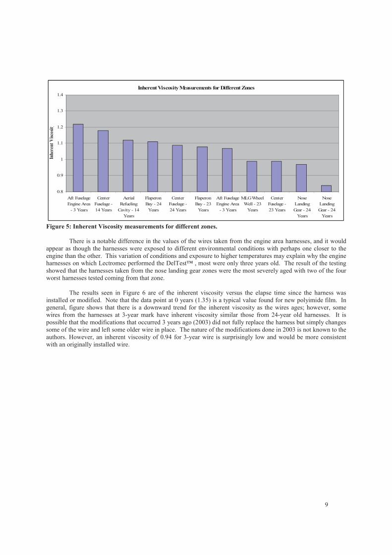
Figure 5: Inherent Viscosity measurements for different zones.
There is a notable difference in the values of the wires taken from the engine area harnesses, and it would
appear as though the harnesses were exposed to different environmental conditions with perhaps one closer to the
engine than the other. This variation of conditions and exposure to higher temperatures may explain why the engine
harnesses on which Lectromec performed the DelTest™ , most were only three years old. The result of the testing
showed that the harnesses taken from the nose landing gear zones were the most severely aged with two of the four
worst harnesses tested coming from that zone.
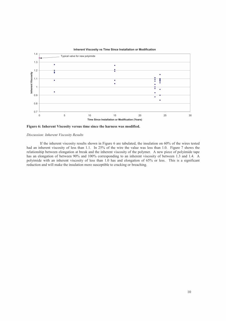
The results seen in Figure 6 are of the inherent viscosity versus the elapse time since the harness was
installed or modified. Note that the data point at 0 years (1.35) is a typical value found for new polyimide film. In
general, figure shows that there is a downward trend for the inherent viscosity as the wires ages; however, some
wires from the harnesses at 3-year mark have inherent viscosity similar those from 24-year old harnesses. It is
possible that the modifications that occurred 3 years ago (2003) did not fully replace the harness but simply changes
some of the wire and left some older wire in place. The nature of the modifications done in 2003 is not known to the
authors. However, an inherent viscosity of 0.94 for 3-year wire is surprisingly low and would be more consistent
with an originally installed wire.
10
Inherent Viscosity vs Time Since Installation or Modification
0.7
0.8
0.9
1
1.1
1.2
1.3
1.4
0 5 10 15 20 25 30
Time Since Installation or Modification (Years)
Inh
ere
nt
Vis
co
sit
y
Typical valve for new polyimide
Figure 6: Inherent Viscosity versus time since the harness was modified.
Discussion: Inherent Viscosity Results
If the inherent viscosity results shown in Figure 6 are tabulated, the insulation on 60% of the wires tested
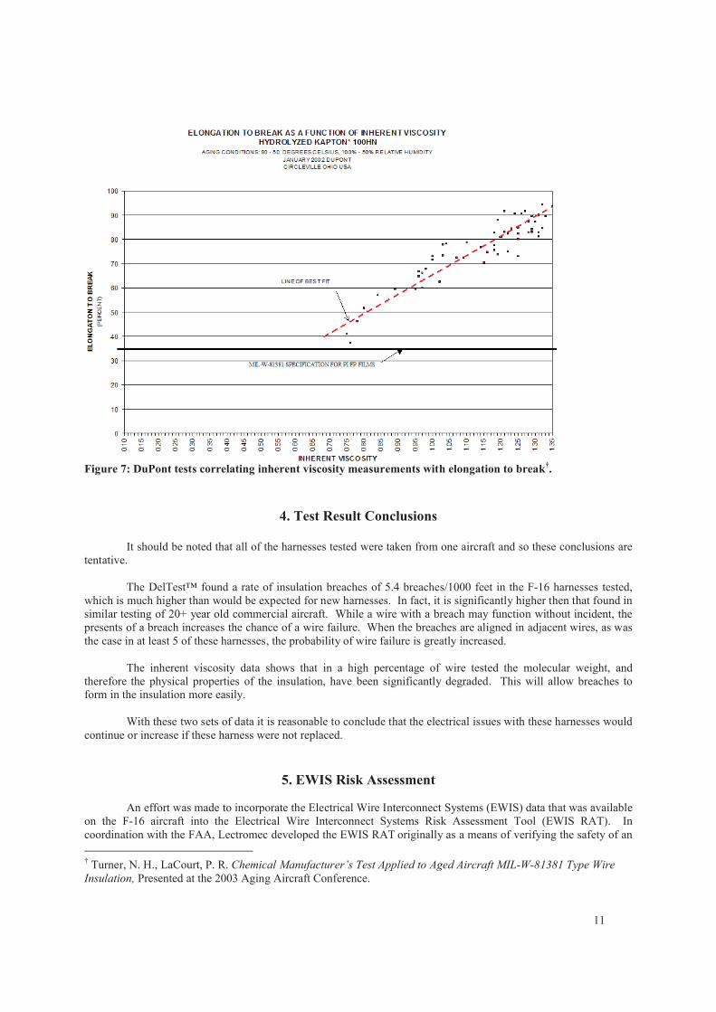
had an inherent viscosity of less than 1.1. In 25% of the wire the value was less than 1.0. Figure 7 shows the
relationship between elongation at break and the inherent viscosity of the polymer. A new piece of polyimide tape
has an elongation of between 90% and 100% corresponding to an inherent viscosity of between 1.3 and 1.4. A
polyimide with an inherent viscosity of less than 1.0 has and elongation of 65% or less. This is a significant
reduction and will make the insulation more susceptible to cracking or breaching.
11
Figure 7: DuPont tests correlating inherent viscosity measurements with elongation to break†.
4. Test Result Conclusions
It should be noted that all of the harnesses tested were taken from one aircraft and so these conclusions are
tentative.
The DelTest™ found a rate of insulation breaches of 5.4 breaches/1000 feet in the F-16 harnesses tested,
which is much higher than would be expected for new harnesses. In fact, it is significantly higher then that found in
similar testing of 20+ year old commercial aircraft. While a wire with a breach may function without incident, the
presents of a breach increases the chance of a wire failure. When the breaches are aligned in adjacent wires, as was
the case in at least 5 of these harnesses, the probability of wire failure is greatly increased.
The inherent viscosity data shows that in a high percentage of wire tested the molecular weight, and
therefore the physical properties of the insulation, have been significantly degraded. This will allow breaches to
form in the insulation more easily.
With these two sets of data it is reasonable to conclude that the electrical issues with these harnesses would
continue or increase if these harness were not replaced.
5. EWIS Risk Assessment
An effort was made to incorporate the Electrical Wire Interconnect Systems (EWIS) data that was available
on the F-16 aircraft into the Electrical Wire Interconnect Systems Risk Assessment Tool (EWIS RAT). In
coordination with the FAA, Lectromec developed the EWIS RAT originally as a means of verifying the safety of an
† Turner, N. H., LaCourt, P. R. Chemical Manufacturer’s Test Applied to Aged Aircraft MIL-W-81381 Type Wire
Insulation, Presented at the 2003 Aging Aircraft Conference.
12
aircraft’s EWIS‡. The target of the RAT is to simplify the process of analyzing the EWIS hazards, potential damage
to structure, flammability issues, as well as provide automation capabilities for aircraft electrical systems. The goal
of this work was to examine the feasibility of performing an EWIS Risk assessment on an aircraft with a reduced
data set (as compared to that which is available during design of the aircraft). With this risk assessment, wire
harnesses that have hazardous failure effects can be identified, highlighted as areas of greater concern. This could
be used to prioritize harness replacement or direct maintenance to take proactive actions if the condition of the wire
in the defined areas becomes questionable.
A. Analysis of the Harnesses Assemblies
The wire ID and termination data in the wire list was analyzed using the EWIS RAT programs. The data wire
segments were arranged into
Circuit Elements: Groups of Wire segments directly connected together (e.g. through connectors)
Circuit Element Families: Groups of Circuit Elements connected sometimes (e.g. through switches)
Circuit Element Controls: Groups of Circuit Element and Circuit Element Families that that are related
through a control device (e.g. a relay).
To this information the additional data of the power bus information and device connection data was included. The
results of this analysis gave, for each harness the number of power (including voltage), signal and ground wires,
along with the distance (resistance) from the power source. In addition, the system/devices that would be
compromised if the harness were lost were also available.
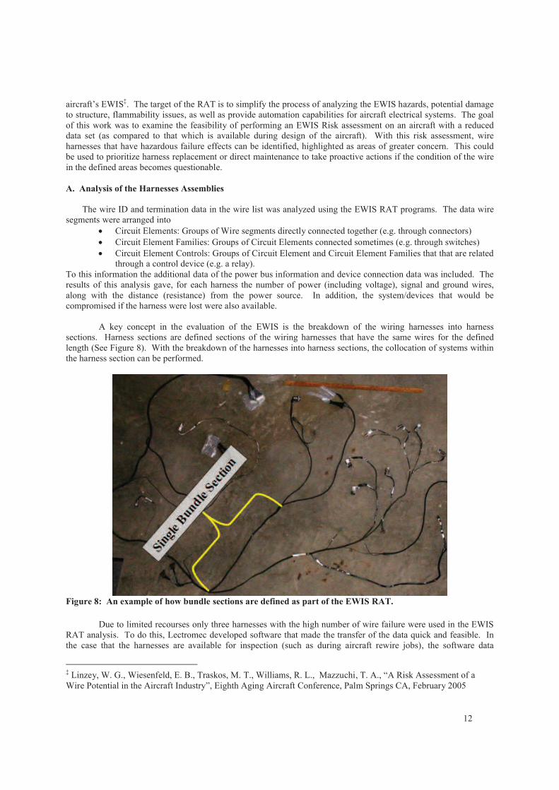
A key concept in the evaluation of the EWIS is the breakdown of the wiring harnesses into harness
sections. Harness sections are defined sections of the wiring harnesses that have the same wires for the defined
length (See Figure 8). With the breakdown of the harnesses into harness sections, the collocation of systems within
the harness section can be performed.
Figure 8: An example of how bundle sections are defined as part of the EWIS RAT.
Due to limited recourses only three harnesses with the high number of wire failure were used in the EWIS
RAT analysis. To do this, Lectromec developed software that made the transfer of the data quick and feasible. In
the case that the harnesses are available for inspection (such as during aircraft rewire jobs), the software data
‡ Linzey, W. G., Wiesenfeld, E. B., Traskos, M. T., Williams, R. L., Mazzuchi, T. A., “A Risk Assessment of a
Wire Potential in the Aircraft Industry”, Eighth Aging Aircraft Conference, Palm Springs CA, February 2005
13
gathering methods have been developed to autonomously break a harness into harness sections and incorporate this
data into the EWIS RAT. For those harnesses, which were available, these were broken into harness sections and
imported into the EWIS model. For those harnesses that were not broken down into harness sections and imported,
the associated wire circuit information was still added to the model; even without the all of the wire harness data an
analysis could be made.
B. Effects of Collocation of Systems and Functions
To determine the effects of loss of systems and device functions on an aircraft requires evaluation be an
expert on the operation of the aircraft. Lectromec did not have access to an expert specific to the F-16 for this
exercise. Therefore Lectromec utilized the expertise of a senior military engineering officer, who commanded a
number of different aircraft fleets, and more than 30 years of field experience. The wires and the associated systems
were that were available were parsed by this fleet maintenance expert and identified those systems which were
redundant of one another and those that, if they failed together, would affect the continued airworthiness of the
aircraft. Additionally, the criticality of each system was identified and assigned one of five categories:
Flight Safety Critical: These are systems, which should they fail, would normally result in the
aircraft being unable to remain airborne. The resultant crash could potentially lead to loss of life,
both to the aircrew and others on the ground.
Safety Critical: These are systems which, should they fail they would affect the overall safety of
the aircraft and its occupants, although they would not necessarily cause the aircraft to crash.
Mission Critical: As its name implies, this is a system which is essential for a successful mission.
However such a system is not necessarily safety or flight safety critical. For example, the
weapons system is mission critical, but should it fail, the only impact would be the inability of the
aircraft to deliver its payload.
Mission Abort: Failure of a system which required the aircraft to return to base without
completing its mission would fall into this category. Radio failure is a prime example of a system
which could lead to mission abort.
General: Other systems, which are neither safety nor mission critical, are lumped together under
the heading of ‘general’. Each general system failure will of course have its own level of impact,
be that a maintenance penalty, cost or time penalties, or a combination of these.
The collocation of the systems was ascertained by routing the wires through the bundle sections defined
above.
C. Probability of Failure
To determine which bundle sections should be focused more closely upon, the probability of a wire failure
within each bundle sections was estimated. The failure probabilities for the bundles sections were taken from the
Paired comparisons failure function that was generated as part of Lectromec’s work with the FAA§. These failure
functions account for such variables as wire gauge, wire insulation, bundle protection methods, environmental
factors, and other attributes that contribute to the failure of the wire. The environmental attributes of each of the
zones were estimated using the reasonable assumptions of the conditions of the aircraft in flight. For those attributes
that contributed to the failure function but were not directly ascertainable with the available information, a constant
value was applied to all bundle sections as to not skew the estimated failure calculation. The probability numbers
for each of the bundle sections would also contribute to the other EWIS assessments discussed later.
§ Mazzuchi, T. A., Linzey, W. G., Bruning, A. M., “A Paired Comparison Experiment for Gathering Expert
Judgment for An Aircraft Wiring Risk Assessment”, Journal of Reliability Engineering and System Safety, March
2007
14
Wire Failure Broken down by Estimated Failure Probability of the Bundle
Section in which the Failure was Found
0
1
2
3
4
5
6
7
Lower 33 Percentile Middle 33 Percentile Upper 33 Percentile
Estimated Probability of Failure of a Wire in a given Harness Environemnt Brokendown
into Three Environmental Groups.
Fai
lure
# F
ound
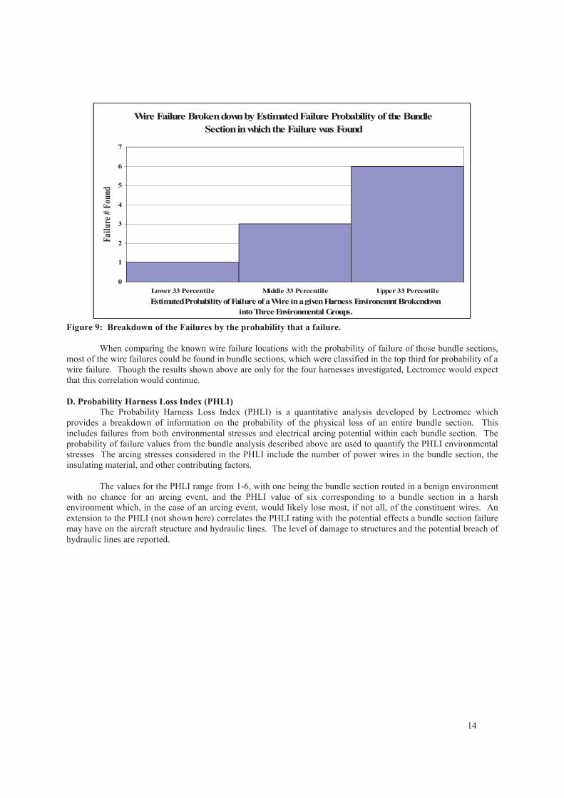
Figure 9: Breakdown of the Failures by the probability that a failure.
When comparing the known wire failure locations with the probability of failure of those bundle sections,
most of the wire failures could be found in bundle sections, which were classified in the top third for probability of a
wire failure. Though the results shown above are only for the four harnesses investigated, Lectromec would expect
that this correlation would continue.
D. Probability Harness Loss Index (PHLI)
The Probability Harness Loss Index (PHLI) is a quantitative analysis developed by Lectromec which
provides a breakdown of information on the probability of the physical loss of an entire bundle section. This
includes failures from both environmental stresses and electrical arcing potential within each bundle section. The
probability of failure values from the bundle analysis described above are used to quantify the PHLI environmental
stresses The arcing stresses considered in the PHLI include the number of power wires in the bundle section, the
insulating material, and other contributing factors.
The values for the PHLI range from 1-6, with one being the bundle section routed in a benign environment
with no chance for an arcing event, and the PHLI value of six corresponding to a bundle section in a harsh
environment which, in the case of an arcing event, would likely lose most, if not all, of the constituent wires. An
extension to the PHLI (not shown here) correlates the PHLI rating with the potential effects a bundle section failure
may have on the aircraft structure and hydraulic lines. The level of damage to structures and the potential breach of
hydraulic lines are reported.
15
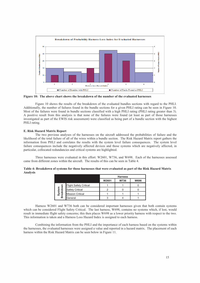
Figure 10: The above chart shows the breakdown of the number of the evaluated harnesses
Figure 10 shows the results of the breakdown of the evaluated bundles sections with regard to the PHLI.
Additionally, the number of failures found in the bundle sections for a given PHLI rating can be seen in Figure 10.
Most of the failures were found in bundle sections classified with a high PHLI rating (PHLI rating greater than 3).
A positive result from this analysis is that none of the failures were found (at least as part of those harnesses
investigated as part of the EWIS risk assessment) were classified as being part of a bundle section with the highest
PHLI rating.
E. Risk Hazard Matrix Report
The two previous analyses of the harnesses on the aircraft addressed the probabilities of failure and the
likelihood of the total failure of all of the wires within a bundle section. The Risk Hazard Matrix report gathers the
information from PHLI and correlates the results with the system level failure consequences. The system level
failure consequences include the negatively affected devices and those systems which are negatively affected, in
particular, collocated redundancies and critical systems are highlighted.
Three harnesses were evaluated in this effort: W2601, W736, and W698. Each of the harnesses assessed
came from different zones within the aircraft. The results of this can be seen in Table 4.
Table 4: Breakdown of systems for those harnesses that were evaluated as part of the Risk Hazard Matrix
Analysis
W2601 W736 W698
Flight Safety Critical 1 1 0
Safety Critical 2 0 0
Mission Critical 1 1 1
General 3 4 1
Harness
Sy
ste
m
Bre
ak
do
wn
Harness W2601 and W736 both can be considered important harnesses given that both contain systems
which can be considered Flight Safety Critical. The last harness, W698, contains no systems which, if lost, would
result in immediate flight safety concerns; this then places W698 as a lower priority harness with respect to the two.
This information is taken and a Harness Loss Hazard Index is assigned to each harness.
Combining the information from the PHLI and the importance of each harness based on the systems within
the harnesses, the evaluated harnesses were assigned a value and reported in a hazard matrix. The placement of each
harness within the Risk Hazard Matrix can be seen below in Figure 11.
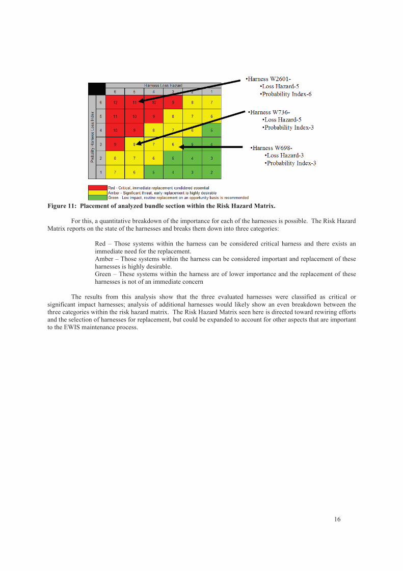
16
Figure 11: Placement of analyzed bundle section within the Risk Hazard Matrix.
For this, a quantitative breakdown of the importance for each of the harnesses is possible. The Risk Hazard
Matrix reports on the state of the harnesses and breaks them down into three categories:
Red – Those systems within the harness can be considered critical harness and there exists an
immediate need for the replacement.
Amber – Those systems within the harness can be considered important and replacement of these
harnesses is highly desirable.
Green – These systems within the harness are of lower importance and the replacement of these
harnesses is not of an immediate concern
The results from this analysis show that the three evaluated harnesses were classified as critical or
significant impact harnesses; analysis of additional harnesses would likely show an even breakdown between the
three categories within the risk hazard matrix. The Risk Hazard Matrix seen here is directed toward rewiring efforts
and the selection of harnesses for replacement, but could be expanded to account for other aspects that are important
to the EWIS maintenance process.
17
6. EWIS Risk Assessment Conclusion
For the limited scope of the EWIS risk assessment that was done for this paper, it appears to Lectromec that
even with a reduced data set which is available to a maintainer, an EWIS risk assessment can be preformed. Not
only can this be performed, but it can be done in a defined, methodical, and effective manner which can provide
useable real results.
The risk analysis of the investigated harnesses showed that the failures in the harnesses did include power
wires. The damage potential assessments from these areas showed that there were a sufficient number of power
wires in the harness to have resulted in the loss of the bundle section. In one case, this would have resulted in
negative affects upon at least one flight safety critical system. Similar results were found when the DelTest™
findings were correlated with the failure affects of the wires.
The Probability Harness Loss Index showed results that can be directly applied to maintenance or repair
operations. The wire failures in the investigated harnesses were found to have high PHLI ratings, which
corresponded to increased chances for the loss of the bundle as the results of environmental strains and/or electrical
arcing events. These were integrated with the severity of failure to produce Risk Hazard Matrix. The Risk Hazard
Matrix can be used as a pragmatic approach to wire harness prioritization efforts.
In this effort, Lectromec has developed many of the necessary techniques for applying the EWIS RAT to
in-service aircraft. Though some work needs to be done with each fleet to evaluate what data is available, it is
probable that for most of the in-service fleets, there exists sufficient information upon which a defined plan can be
implemented. The techniques are modular and dynamic which allow great variability from the input data.
18
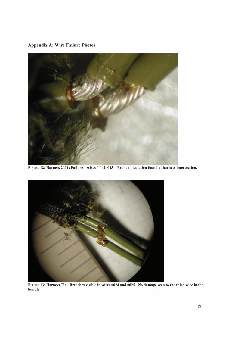
Appendix A: Wire Failure Photos
Figure 12: Harness 2601: Failure – wires # 042, 043 – Broken insulation found at harness intersection.
Figure 13: Harness 736. Breaches visible in wires #024 and #025. No damage seen to the third wire in the
bundle.
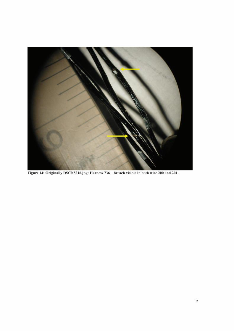
19
Figure 14: Originally DSCN5216.jpg: Harness 736 – breach visible in both wire 200 and 201.
20
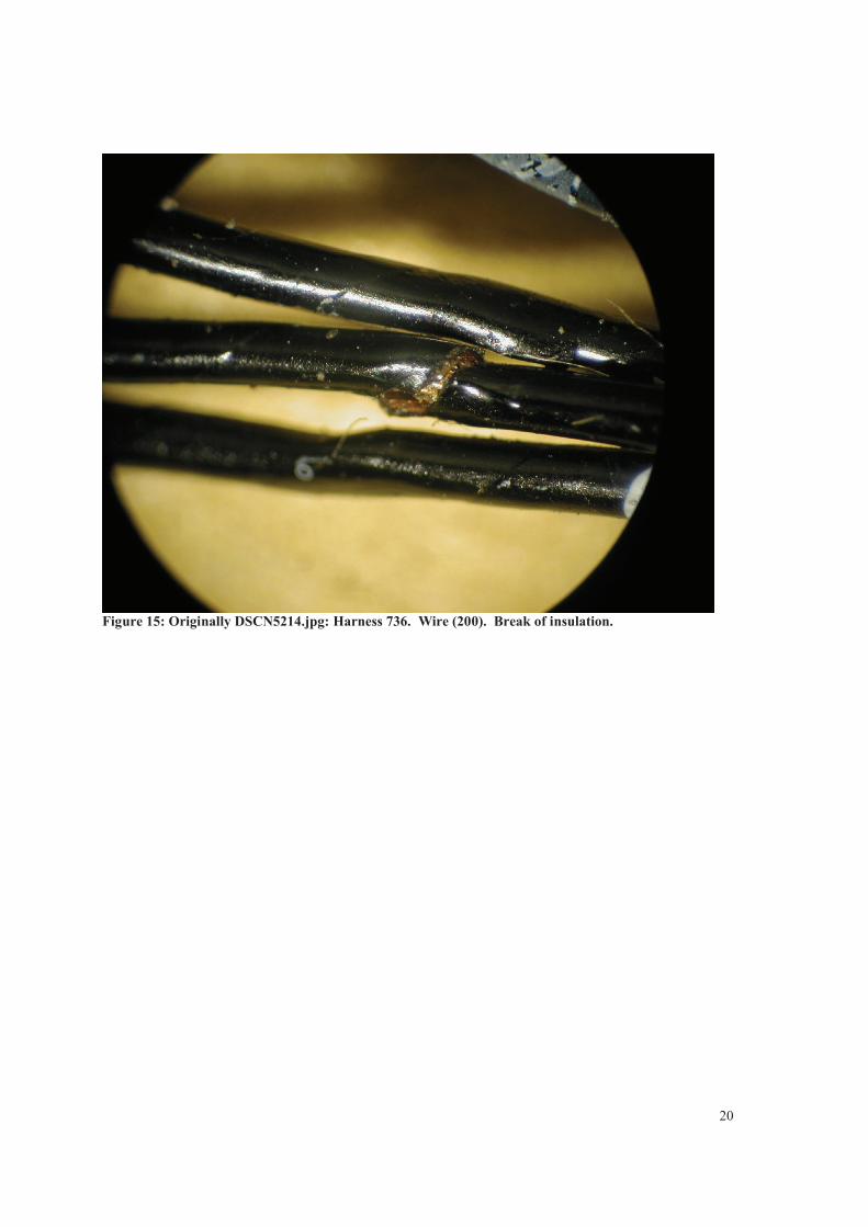
Figure 15: Originally DSCN5214.jpg: Harness 736. Wire (200). Break of insulation.
21
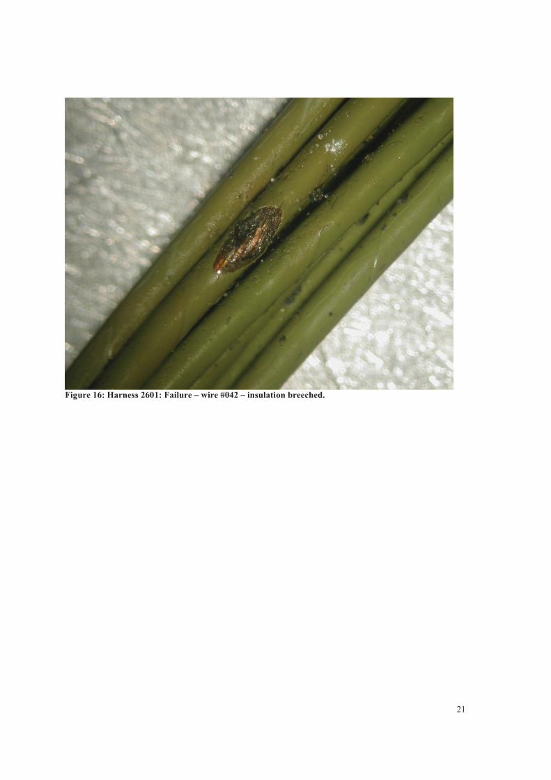
Figure 16: Harness 2601: Failure – wire #042 – insulation breeched.
22
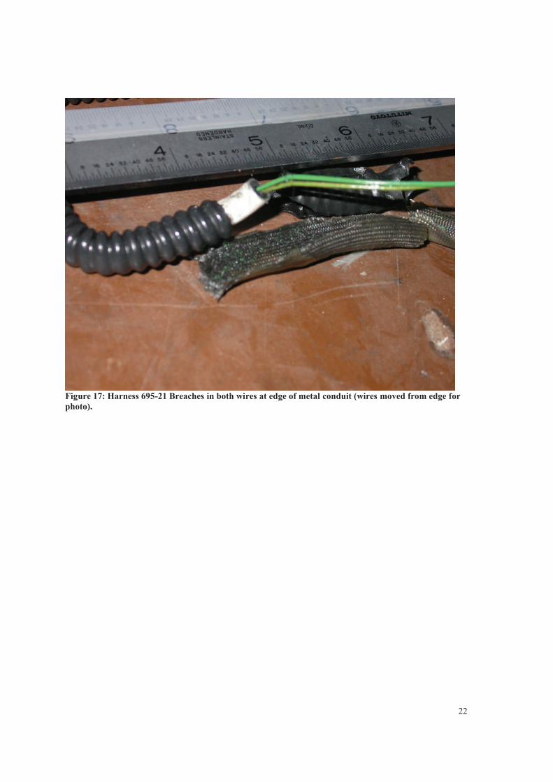
Figure 17: Harness 695-21 Breaches in both wires at edge of metal conduit (wires moved from edge for
photo).
23
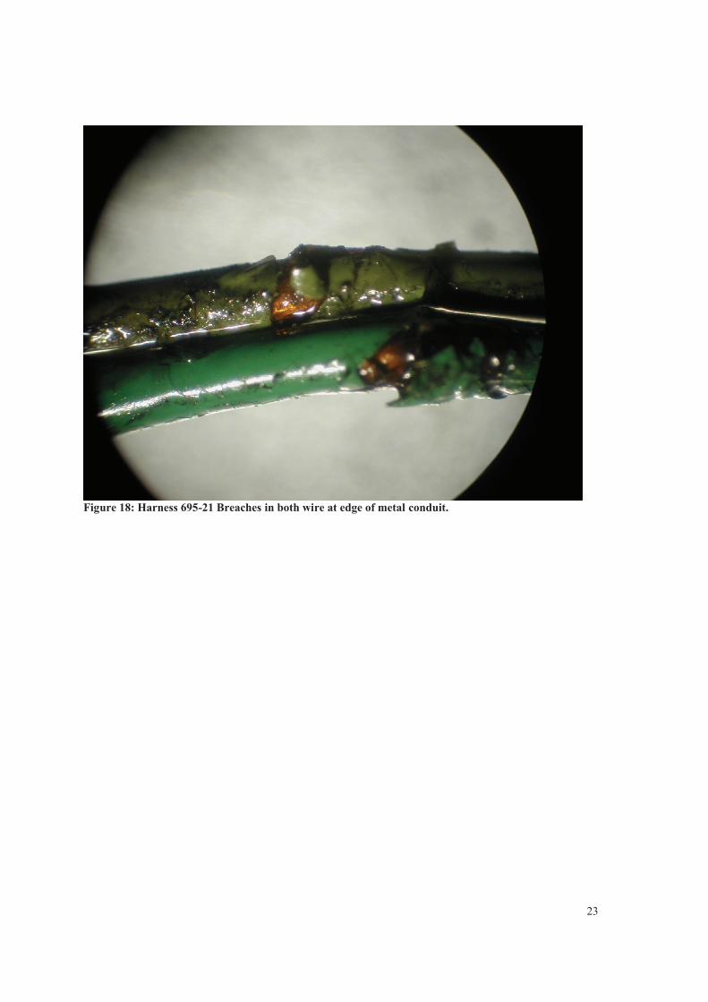
Figure 18: Harness 695-21 Breaches in both wire at edge of metal conduit.