Embed Size (px)
Citation preview
EVOLVE® Proline PlusRadial Head and Repair System
SURGIC AL TECHNIQUE
Device Description
Intended Use
Preoperative Planning
Surgical Technique
Skin Incision
Direct Lateral Dissection
Resection
Trial Head Selection
Stem Broaching
Neck Planing
Trial Stem Selection
Trial Stem and Head Insertion
Validate Trial Sizing
Trial Head and Stem Removal
Implant Insertion Using Back Table Implant Assembly
Implant Insertion Using In Situ Assembly
Locker Assembly
Closure
Explant Information
Postoperative Management
EVOLVE® Proline Plus Radial Head and Repair System
Screw Preparation
Screw Placement
Postoperative Management
EVOLVE® TRIAD™ 2.5mm Cannulated Bone Scews
EVOLVE® TRIAD™ 2.0mm Bone Scews (Outside Plate)
Ordering Information
Chapter 1 3
Chapter 2 8
Chapter 3 10
Chapter 4 11
11
12
13
14
14
15
15
16
17
17
17
18
18
19
20
20
21
23
23
24
24
26
Appendix 27
Contents
Wright recognizes that proper surgical procedures and techniques are the responsibility of the medical professional. The following guidelines are furnished for information purposes only. Each surgeon must evaluate the appropriateness of the procedures based on his or her personal medical training, experience, and patient condition. Prior to use of the system, the surgeon should refer to the product Instructions For Use package inserts 146884 and 146886 for additional warnings, precautions, indications, contraindications and adverse effects. Instructions For Use package inserts are also available by contacting the manufacturer. Contact information can be found on the back of this surgical technique. The Instructions For Use package inserts are available on wmt.com under the link for Prescribing Information.
Please contact your local Wright representative for product availability.
3
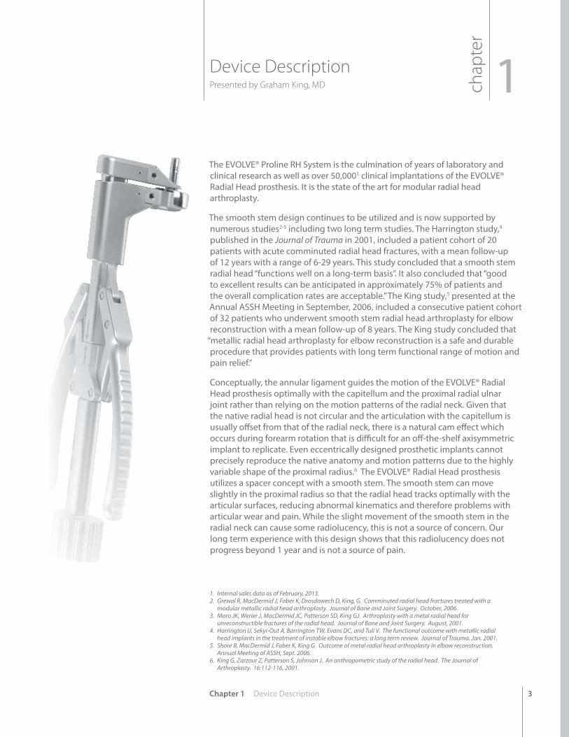
Device DescriptionPresented by Graham King, MD
The EVOLVE® Proline RH System is the culmination of years of laboratory and clinical research as well as over 50,0001 clinical implantations of the EVOLVE® Radial Head prosthesis. It is the state of the art for modular radial head arthroplasty.
The smooth stem design continues to be utilized and is now supported by numerous studies2-5 including two long term studies. The Harrington study,4 published in the Journal of Trauma in 2001, included a patient cohort of 20 patients with acute comminuted radial head fractures, with a mean follow-up of 12 years with a range of 6-29 years. This study concluded that a smooth stem radial head “functions well on a long-term basis”. It also concluded that “good to excellent results can be anticipated in approximately 75% of patients and the overall complication rates are acceptable.” The King study,5 presented at the Annual ASSH Meeting in September, 2006, included a consecutive patient cohort of 32 patients who underwent smooth stem radial head arthroplasty for elbow reconstruction with a mean follow-up of 8 years. The King study concluded that
“metallic radial head arthroplasty for elbow reconstruction is a safe and durable procedure that provides patients with long term functional range of motion and pain relief.”
Conceptually, the annular ligament guides the motion of the EVOLVE® Radial Head prosthesis optimally with the capitellum and the proximal radial ulnar joint rather than relying on the motion patterns of the radial neck. Given that the native radial head is not circular and the articulation with the capitellum is usually offset from that of the radial neck, there is a natural cam effect which occurs during forearm rotation that is difficult for an off-the-shelf axisymmetric implant to replicate. Even eccentrically designed prosthetic implants cannot precisely reproduce the native anatomy and motion patterns due to the highly variable shape of the proximal radius.6 The EVOLVE® Radial Head prosthesis utilizes a spacer concept with a smooth stem. The smooth stem can move slightly in the proximal radius so that the radial head tracks optimally with the articular surfaces, reducing abnormal kinematics and therefore problems with articular wear and pain. While the slight movement of the smooth stem in the radial neck can cause some radiolucency, this is not a source of concern. Our long term experience with this design shows that this radiolucency does not progress beyond 1 year and is not a source of pain.
Chapter 1 Device Description
1. Internal sales data as of February, 2013.2. Grewal R, MacDermid J, Faber K, Drosdowech D, King, G. Comminuted radial head fractures treated with a
modular metallic radial head arthroplasty. Journal of Bone and Joint Surgery. October, 2006.3. Moro JK, Werier J, MacDermid JC, Patterson SD, King GJ. Arthroplasty with a metal radial head for
unreconstructible fractures of the radial head. Journal of Bone and Joint Surgery. August, 2001.4. Harrington IJ, Sekyi-Out A, Barrington TW, Evans DC, and Tuli V. The functional outcome with metallic radial
head implants in the treatment of instable elbow fractures: a long term review. Journal of Trauma. Jan. 2001.5. Shore B, MacDermid J, Faber K, King G. Outcome of metal radial head arthroplasty in elbow reconstruction.
Annual Meeting of ASSH, Sept. 2006.6. King G, Zarzour Z, Patterson S, Johnson J. An anthropometric study of the radial head. The Journal of
Arthroplasty. 16:112-116, 2001.
chap
ter
1
4
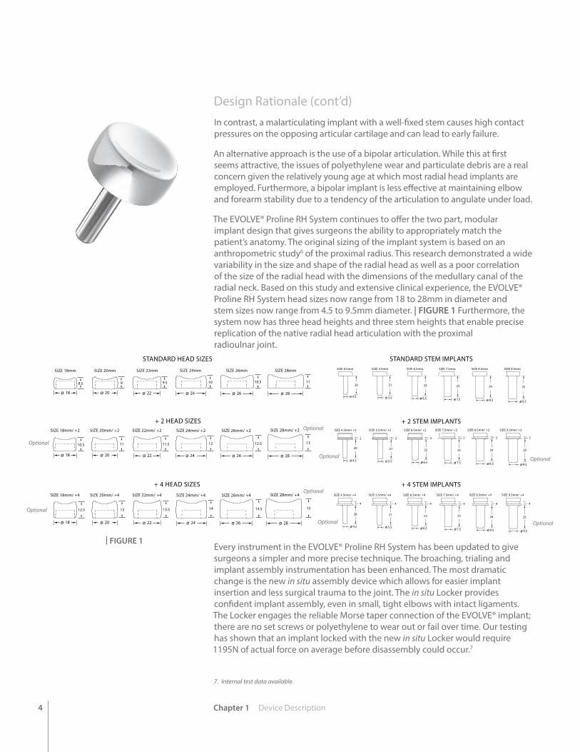
Design Rationale (cont’d)In contrast, a malarticulating implant with a well-fixed stem causes high contact pressures on the opposing articular cartilage and can lead to early failure.
An alternative approach is the use of a bipolar articulation. While this at first seems attractive, the issues of polyethylene wear and particulate debris are a real concern given the relatively young age at which most radial head implants are employed. Furthermore, a bipolar implant is less effective at maintaining elbow and forearm stability due to a tendency of the articulation to angulate under load.
The EVOLVE® Proline RH System continues to offer the two part, modular implant design that gives surgeons the ability to appropriately match the patient’s anatomy. The original sizing of the implant system is based on an anthropometric study6 of the proximal radius. This research demonstrated a wide variability in the size and shape of the radial head as well as a poor correlation of the size of the radial head with the dimensions of the medullary canal of the radial neck. Based on this study and extensive clinical experience, the EVOLVE® Proline RH System head sizes now range from 18 to 28mm in diameter and stem sizes now range from 4.5 to 9.5mm diameter. | FIGURE 1 Furthermore, the system now has three head heights and three stem heights that enable precise replication of the native radial head articulation with the proximal radioulnar joint.
Every instrument in the EVOLVE® Proline RH System has been updated to give surgeons a simpler and more precise technique. The broaching, trialing and implant assembly instrumentation has been enhanced. The most dramatic change is the new in situ assembly device which allows for easier implant insertion and less surgical trauma to the joint. The in situ Locker provides confident implant assembly, even in small, tight elbows with intact ligaments. The Locker engages the reliable Morse taper connection of the EVOLVE® implant; there are no set screws or polyethylene to wear out or fail over time. Our testing has shown that an implant locked with the new in situ Locker would require 1195N of actual force on average before disassembly could occur.7
7. Internal test data available.
| FIGURE 1
SIZE 18mm SIZE 20mm SIZE 22mm SIZE 24mm SIZE 26mm SIZE 28mm
SIZE 18mm/ +2 SIZE 20mm/ +2 SIZE 22mm/ +2 SIZE 24mm/ +2 SIZE 26mm/ +2 SIZE 28mm/ +2
9 9.5 10 10.5 118.5
11 11.5 12 12.5 1310.5
SIZE 18mm/ +4 SIZE 20mm/ +4 SIZE 22mm/ +4 SIZE 24mm/ +4 SIZE 26mm/ +4 SIZE 28mm/ +4
13 13.5 14 14.5 1512.5
18 20 22 24 26 28
18 20 22 24 26 28
18 20 22 24 26 28
STANDARD HEAD SIZES
+ 2 HEAD SIZES
+ 4 HEAD SIZES
STANDARD STEM IMPLANTS
+ 2 STEM IMPLANTS
+ 4 STEM IMPLANTS
SIZE 4.5mm SIZE 5.5mm SIZE 6.5mm SIZE 7.5mm SIZE 8.5mm SIZE 9.5mm
SIZE 4.5mm/ +2 SIZE 5.5mm/ +2 SIZE 6.5mm/ +2 SIZE 7.5mm/ +2 SIZE 8.5mm/ +2 SIZE 9.5mm/ +2
SIZE 4.5mm/ +4 SIZE 5.5mm/ +4 SIZE 6.5mm/ +4 SIZE 7.5mm/ +4 SIZE 8.5mm/ +4 SIZE 9.5mm/ +4
20 21 22 23 24 25
20
4.5 5.5 6.5 7.5 8.5 9.5
4.5
2
21
5.5
2
22
6.5
2
23
7.5
2
24
8.5
2
25
9.5
2
20
4.5
4
21
5.5
4
22
6.5
4
23
7.5
4
24
8.5
4
25
9.5
4
Chapter 1 Device Description
Optional
OptionalOptional
Optional
Optional
Optional
Optional
Optional
5Chapter 1 Device Description
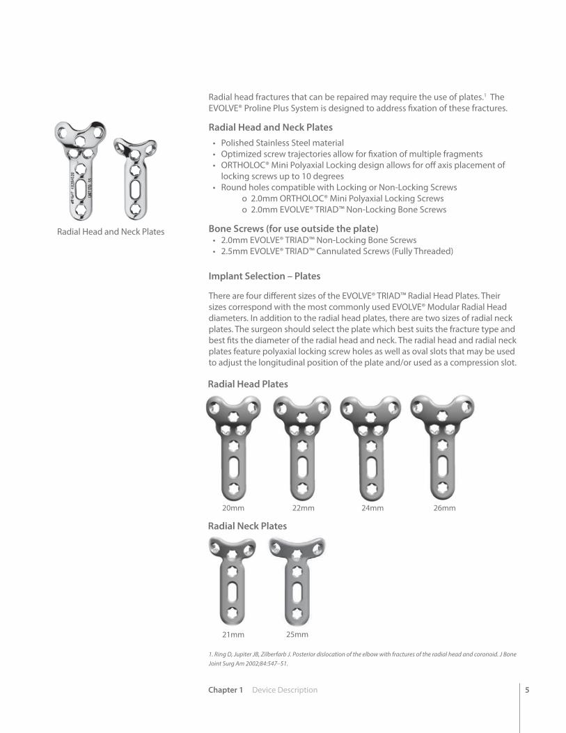
Radial head fractures that can be repaired may require the use of plates.1 The EVOLVE® Proline Plus System is designed to address fixation of these fractures.
Radial Head and Neck Plates• Polished Stainless Steel material• Optimized screw trajectories allow for fixation of multiple fragments• ORTHOLOC® Mini Polyaxial Locking design allows for off axis placement of
locking screws up to 10 degrees• Round holes compatible with Locking or Non-Locking Screws
o 2.0mm ORTHOLOC® Mini Polyaxial Locking Screws o 2.0mm EVOLVE® TRIAD™ Non-Locking Bone Screws
Bone Screws (for use outside the plate)• 2.0mm EVOLVE® TRIAD™ Non-Locking Bone Screws• 2.5mm EVOLVE® TRIAD™ Cannulated Screws (Fully Threaded)
Radial Head and Neck Plates
1. Ring D, Jupiter JB, Zilberfarb J. Posterior dislocation of the elbow with fractures of the radial head and coronoid. J Bone Joint Surg Am 2002;84:547–51.
Implant Selection – Plates
There are four different sizes of the EVOLVE® TRIAD™ Radial Head Plates. Their sizes correspond with the most commonly used EVOLVE® Modular Radial Head diameters. In addition to the radial head plates, there are two sizes of radial neck plates. The surgeon should select the plate which best suits the fracture type and best fits the diameter of the radial head and neck. The radial head and radial neck plates feature polyaxial locking screw holes as well as oval slots that may be used to adjust the longitudinal position of the plate and/or used as a compression slot.
20mm 22mm 24mm 26mm
21mm 25mm
Radial Head Plates
Radial Neck Plates
6 Chapter 1 Device Description
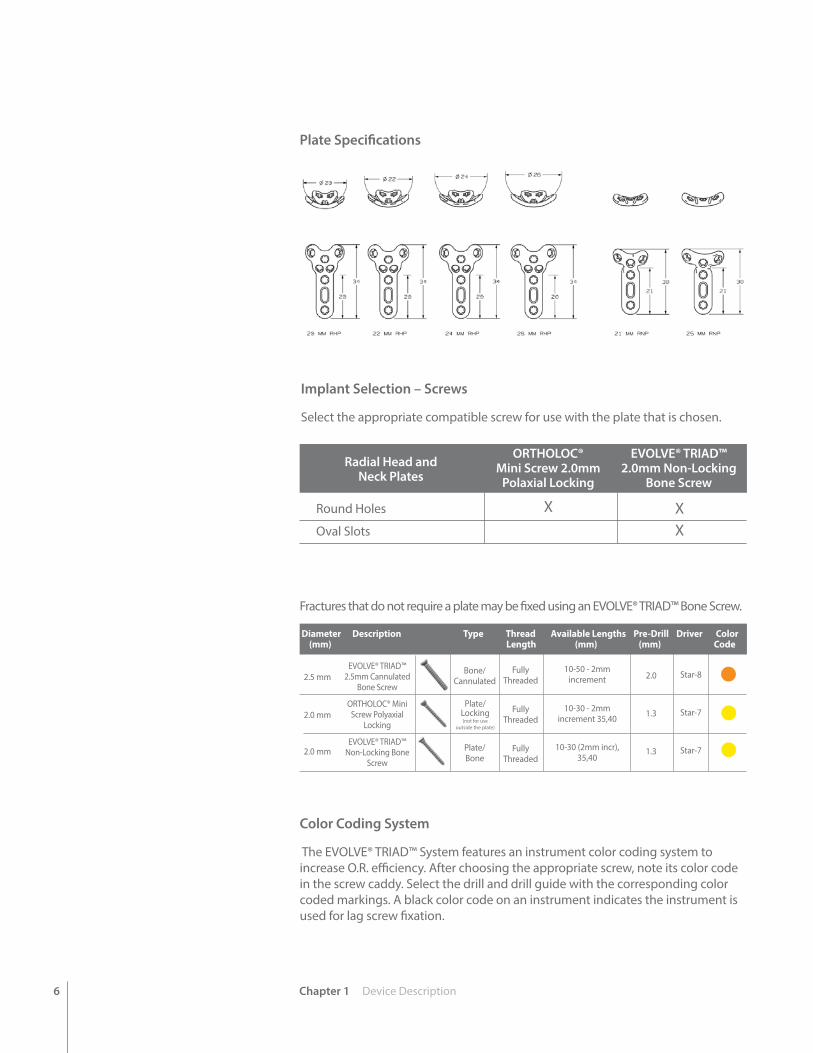
Implant Selection – Screws
Select the appropriate compatible screw for use with the plate that is chosen.
Fractures that do not require a plate may be fixed using an EVOLVE® TRIAD™ Bone Screw.
Color Coding System
The EVOLVE® TRIAD™ System features an instrument color coding system to increase O.R. efficiency. After choosing the appropriate screw, note its color code in the screw caddy. Select the drill and drill guide with the corresponding color coded markings. A black color code on an instrument indicates the instrument is used for lag screw fixation.
2.0
1.3
1.3
2.5 mm
2.0 mm
2.0 mm
EVOLVE® TRIAD™ 2.5mm Cannulated
Bone Screw
ORTHOLOC® Mini Screw Polyaxial
Locking
EVOLVE® TRIAD™ Non-Locking Bone
Screw
Bone/Cannulated
Plate/Bone
Fully Threaded
Fully Threaded
Fully Threaded
10-50 - 2mm increment
10-30 - 2mm increment 35,40
10-30 (2mm incr), 35,40
Star-8
Star-7
Star-7
Diameter Description Type Thread Available Lengths Pre-Drill Driver Color (mm) Length (mm) (mm) Code
Plate Specifications
Round Holes
Oval Slots
ORTHOLOC® Mini Screw 2.0mm
Polaxial Locking
EVOLVE® TRIAD™2.0mm Non-Locking
Bone Screw X X
Radial Head and Neck Plates
Plate/Locking (not for use
outside the plate)
X

Chapter 1 Device Description 7
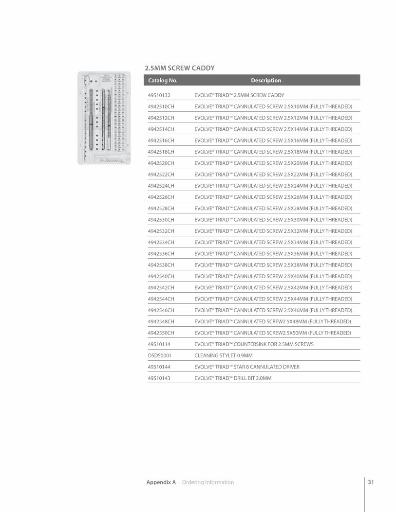
1. Cleaning Stylet2. 2.0mm Drill3. 2.5mm Drill (space for optional overdrill to be added to the set)4. Countersink for 2.5mm Screws5. Star-8 Driver6. 2.5mm Screws
1
2
3
4
5 6
2.5mm Caddy
1. Screw Gripper2. 2.0mm Locking Screws3. 2.0mm Non-Locking Screws4. 1.3mm Drill5. 2.0mm Drill (overdrill)6. Countersink for 2.0 mm Screws7. Star-7 Straight Driver8. Star-7 Self Retaining Driver
1
2
3
4
5
6
7
8
2.0mm Caddy
8 Chapter 2 Intended Use
Intended Use 2chap
ter
EVOLVE® TRIAD™ Fixation System
IndicationsWright’s EVOLVE® Proline Plus Radial Head and Repair System is a set configuration designed to address radial head fractures. It combines parts of two systems: EVOLVE® Proline and EVOLVE® TRIAD™.
Wright’s EVOLVE® TRIAD™ Fixation System is intended for fixation of fractures, osteotomies and non-unions of the olecranon, radius and ulna. The EVOLVE® Proline Plus Radial Head and Repair System excludes two groups from the TRIAD™ system – it does not include the coronoid plates or the 1.5mm screws.
The ORTHOLOC® Mini Polyaxial Locking Screws are intended for use with Wright’s plates manufactured from implant grade stainless steel that accept ORTHOLOC® Mini Polyaxial Locking Screws.
The EVOLVE® TRIAD™ Bone Screws are indicated for use in bone reconstruction, osteotomy, arthrodesis, joint fusion, fracture repair, and fracture fixation of bones appropriate for the size of the device, including the scapula, long bones (ulna, radius and humerus) and small bones (metacarpals, metatarsals, and phalanges).
Contraindications• Infection
• Physiologically or psychologically inadequate patient
• Inadequate skin, bone, or neurovascular status
• Irreparable tendon system
• Possibility for conservative treatment
• Growing patients with open epiphyses
• Patients with high levels of activity
IMPORTANT: Please consult Instructions For Use package inserts 146884 and 146886 for additional risk information.
Chapter 2 Intended Use 9
EVOLVE® Proline Plus Radial Head and Repair System Wright’s EVOLVE® Proline Plus Radial Head and Repair System is a setconfiguration designed to address radial head fractures. It combines parts of twosystems: EVOLVE® Proline and EVOLVE® TRIAD™. This IFU section is for the radial head prosthesis, while the previous page IFU was for the TRIAD™ plates and screws.
The Radial Head Implant is available as a modular, two-piece, intramedullary-stemmed implant. The device acts as a spacer in the radio-humeral joint.
The Radial Head Implants have been sterilized. A sizing set, supplied non-sterile and not suitable for implantation, is available for proper size determination during surgery.
IndicationsUse of the Radial Head Implant may be considered for:
• Replacement of the radial head for degenerative or post-traumatic disabilities presenting pain, crepitation, and decreased motion at the radio-humeral and/or proximal radioulnar joint with:
> joint destruction and/or subluxation
> resistance to conservative treatment
• Primary replacement after fracture of the radial head.
• Symptomatic sequelae after radial head resection.
• Revision following failed radial head arthroplasty. Visible on x-ray; and/or resistance to conservative treatment.
Contraindications• Infection
• Physiologically or psychologically inadequate patient
• Inadequate skin, bone, or neurovascular status
• Irreparable tendon system
• Possibility for conservative treatment
• Growing patients with open epiphyses
• Patients with high levels of activity
IMPORTANT: Please consult Instructions For Use package inserts 146884 and 146886 for additional risk information.
10 Chapter 3 Preoperative Planning
chap
ter
3Preoperative Planning
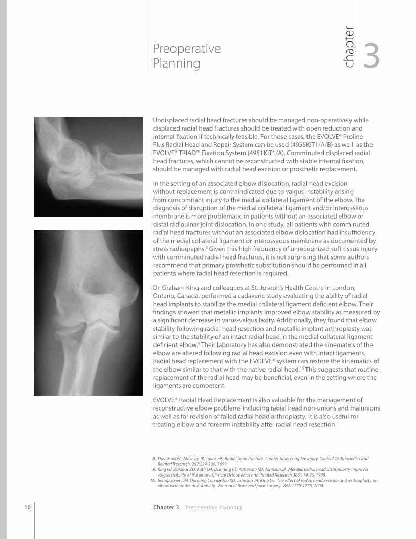
Undisplaced radial head fractures should be managed non-operatively while displaced radial head fractures should be treated with open reduction and internal fixation if technically feasible. For those cases, the EVOLVE® Proline Plus Radial Head and Repair System can be used (4955KIT1/A/B) as well as the EVOLVE® TRIAD™ Fixation System (4951KIT1/A). Comminuted displaced radial head fractures, which cannot be reconstructed with stable internal fixation, should be managed with radial head excision or prosthetic replacement.
In the setting of an associated elbow dislocation, radial head excision without replacement is contraindicated due to valgus instability arising from concomitant injury to the medial collateral ligament of the elbow. The diagnosis of disruption of the medial collateral ligament and/or interosseous membrane is more problematic in patients without an associated elbow or distal radioulnar joint dislocation. In one study, all patients with comminuted radial head fractures without an associated elbow dislocation had insufficiency of the medial collateral ligament or interosseous membrane as documented by stress radiographs.8 Given this high frequency of unrecognized soft tissue injury with comminuted radial head fractures, it is not surprising that some authors recommend that primary prosthetic substitution should be performed in all patients where radial head resection is required.
Dr. Graham King and colleagues at St. Joseph’s Health Centre in London, Ontario, Canada, performed a cadaveric study evaluating the ability of radial head implants to stabilize the medial collateral ligament deficient elbow. Their findings showed that metallic implants improved elbow stability as measured by a significant decrease in varus-valgus laxity. Additionally, they found that elbow stability following radial head resection and metallic implant arthroplasty was similar to the stability of an intact radial head in the medial collateral ligament deficient elbow.9 Their laboratory has also demonstrated the kinematics of the elbow are altered following radial head excision even with intact ligaments. Radial head replacement with the EVOLVE® system can restore the kinematics of the elbow similar to that with the native radial head.10 This suggests that routine replacement of the radial head may be beneficial, even in the setting where the ligaments are competent.
EVOLVE® Radial Head Replacement is also valuable for the management of reconstructive elbow problems including radial head non-unions and malunions as well as for revision of failed radial head arthroplasty. It is also useful for treating elbow and forearm instability after radial head resection.
8. Davidson PA, Moseley JB, Tullos HS. Radial head fracture: A potentially complex injury. Clinical Orthopaedics and Related Research. 297:224-230, 1993.
9. King GJ, Zarzour ZD, Rath DA, Dunning CE, Patterson SD, Johnson JA. Metallic radial head arthroplasty improves valgus stability of the elbow. Clinical Orthopedics and Related Research 368:114-25, 1999.
10. Beingessner DM, Dunning CE, Gordon KD, Johnson JA, King GJ. The effect of radial head excision and arthroplasty on elbow kinematics and stability. Journal of Bone and joint Surgery. 86A:1730-1739, 2004.
Chapter 4 Surgical Technique 11
EVOLVE® Proline Plus
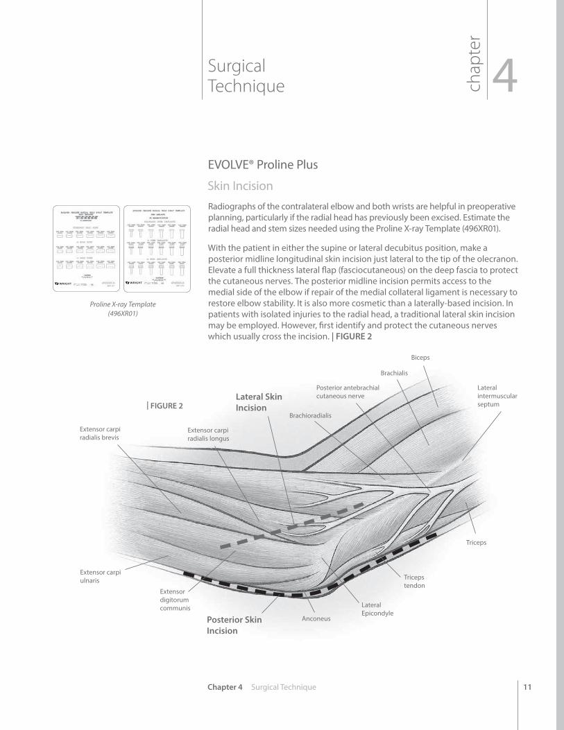
Skin Incision Radiographs of the contralateral elbow and both wrists are helpful in preoperative planning, particularly if the radial head has previously been excised. Estimate the radial head and stem sizes needed using the Proline X-ray Template (496XR01).
With the patient in either the supine or lateral decubitus position, make a posterior midline longitudinal skin incision just lateral to the tip of the olecranon. Elevate a full thickness lateral flap (fasciocutaneous) on the deep fascia to protect the cutaneous nerves. The posterior midline incision permits access to the medial side of the elbow if repair of the medial collateral ligament is necessary to restore elbow stability. It is also more cosmetic than a laterally-based incision. In patients with isolated injuries to the radial head, a traditional lateral skin incision may be employed. However, first identify and protect the cutaneous nerves which usually cross the incision. | FIGURE 2
Posterior Skin Incision
Lateral Skin Incision
Lateral intermuscular septum
Biceps
Brachialis
Posterior antebrachial cutaneous nerve
Brachioradialis
Extensor carpi radialis longus
Extensor carpi radialis brevis
Extensor carpi ulnaris
Extensor digitorum communis
Anconeus
Lateral Epicondyle
Triceps tendon
Triceps
chap
ter
Surgical Technique 4
| FIGURE 2
Proline X-ray Template(496XR01)
12
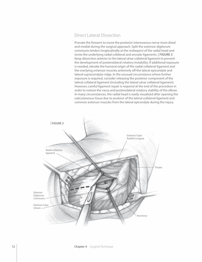
Direct Lateral DissectionPronate the forearm to move the posterior interosseous nerve more distal and medial during the surgical approach. Split the extensor digitorum communis tendon longitudinally at the midaspect of the radial head and incise the underlying radial collateral and annular ligaments. | FIGURE 3 Keep dissection anterior to the lateral ulnar collateral ligament to prevent the development of posterolateral rotatory instability. If additional exposure is needed, elevate the humeral origin of the radial collateral ligament and the overlying extensor muscles anteriorly off the lateral epicondyle and lateral supracondylar ridge. In the unusual circumstance where further exposure is required, consider releasing the posterior component of the lateral collateral ligament (including the lateral ulnar collateral ligament). However, careful ligament repair is required at the end of the procedure in order to restore the varus and posterolateral rotatory stability of the elbow. In many circumstances, the radial head is easily visualized after opening the subcutaneous tissue due to avulsion of the lateral collateral ligament and common extensor muscles from the lateral epicondyle during the injury.
Chapter 4 Surgical Technique
Radial collateral ligament
Extensor Carpi Radialis Longusa
Triceps
Anconeus
Extensor Digitorum Communis
Extensor Carpi Ulnaris
| FIGURE 3
13Chapter 4 Surgical Technique
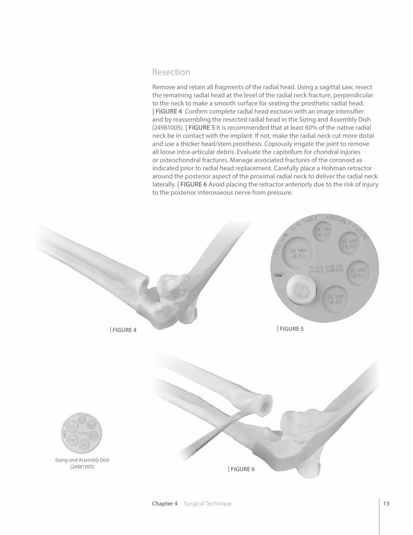
ResectionRemove and retain all fragments of the radial head. Using a sagittal saw, resect the remaining radial head at the level of the radial neck fracture, perpendicular to the neck to make a smooth surface for seating the prosthetic radial head. | FIGURE 4 Confirm complete radial head excision with an image intensifier and by reassembling the resected radial head in the Sizing and Assembly Dish (24981005). | FIGURE 5 It is recommended that at least 60% of the native radial neck be in contact with the implant. If not, make the radial neck cut more distal and use a thicker head/stem prosthesis. Copiously irrigate the joint to remove all loose intra-articular debris. Evaluate the capitellum for chondral injuries or osteochondral fractures. Manage associated fractures of the coronoid as indicated prior to radial head replacement. Carefully place a Hohman retractor around the posterior aspect of the proximal radial neck to deliver the radial neck laterally. | FIGURE 6 Avoid placing the retractor anteriorly due to the risk of injury to the posterior interosseous nerve from pressure.
| FIGURE 4 | FIGURE 5
| FIGURE 6
Sizing and Assembly Dish(24981005)
14
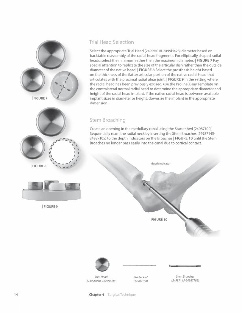
Trial Head SelectionSelect the appropriate Trial Head (2499H018-2499H428) diameter based on backtable reassembly of the radial head fragments. For elliptically shaped radial heads, select the minimum rather than the maximum diameter. | FIGURE 7 Pay special attention to replicate the size of the articular dish rather than the outside diameter of the native head. | FIGURE 8 Select the prosthesis height based on the thickness of the flatter articular portion of the native radial head that articulates with the proximal radial ulnar joint. | FIGURE 9 In the setting where the radial head has been previously excised, use the Proline X-ray Template on the contralateral normal radial head to determine the appropriate diameter and height of the radial head implant. If the native radial head is between available implant sizes in diameter or height, downsize the implant in the appropriate dimension.
Stem Broaching Create an opening in the medullary canal using the Starter Awl (24987100). Sequentially ream the radial neck by inserting the Stem Broaches (24987145-24987105) to the depth indicators on the Broaches | FIGURE 10 until the Stem Broaches no longer pass easily into the canal due to cortical contact.
Chapter 4 Surgical Technique
depth indicator
| FIGURE 7
Trial Head(2499H018-2499H428)
| FIGURE 8
| FIGURE 9
| FIGURE 10
Starter Awl(24987100)
Stem Broaches(24987145-24987105)
15Chapter 4 Surgical Technique
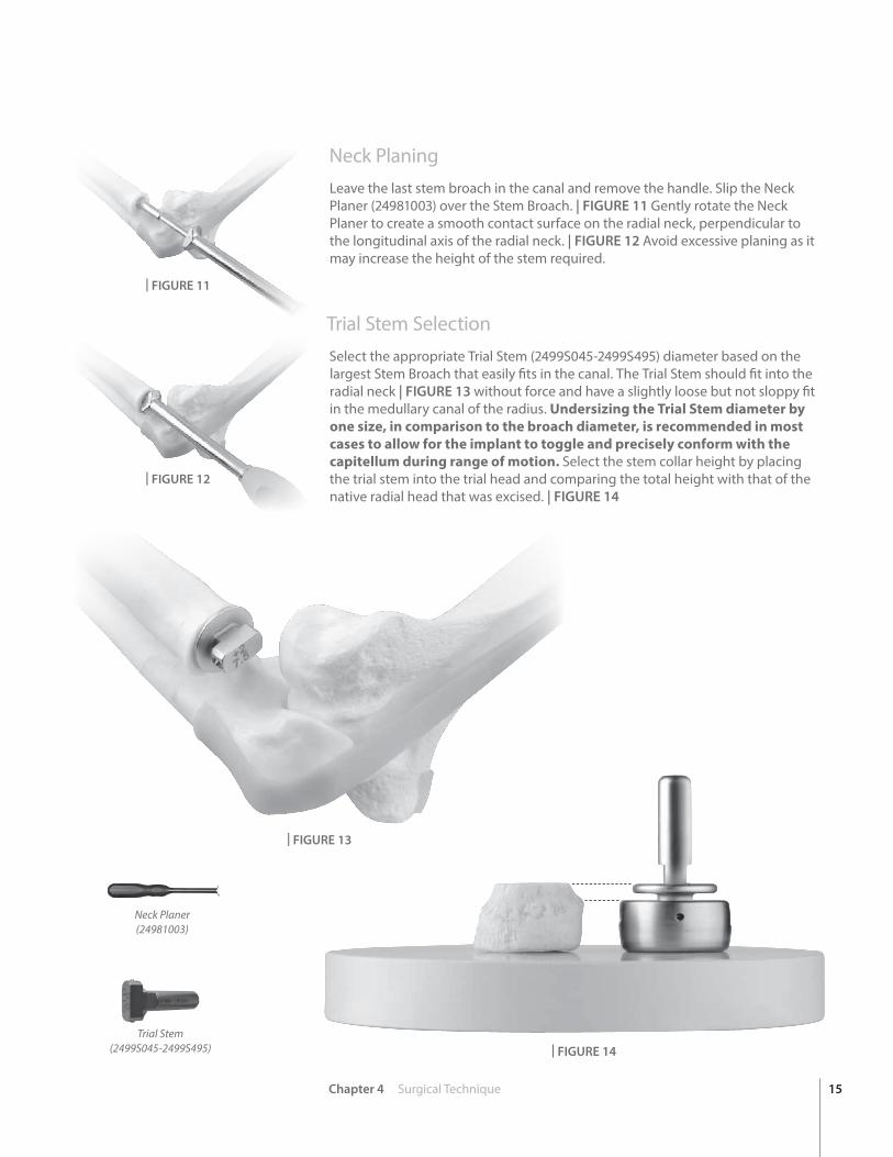
Neck Planing Leave the last stem broach in the canal and remove the handle. Slip the Neck Planer (24981003) over the Stem Broach. | FIGURE 11 Gently rotate the Neck Planer to create a smooth contact surface on the radial neck, perpendicular to the longitudinal axis of the radial neck. | FIGURE 12 Avoid excessive planing as it may increase the height of the stem required.
Trial Stem SelectionSelect the appropriate Trial Stem (2499S045-2499S495) diameter based on the largest Stem Broach that easily fits in the canal. The Trial Stem should fit into the radial neck | FIGURE 13 without force and have a slightly loose but not sloppy fit in the medullary canal of the radius. Undersizing the Trial Stem diameter by one size, in comparison to the broach diameter, is recommended in most cases to allow for the implant to toggle and precisely conform with the capitellum during range of motion. Select the stem collar height by placing the trial stem into the trial head and comparing the total height with that of the native radial head that was excised. | FIGURE 14
| FIGURE 11
| FIGURE 12
| FIGURE 13
| FIGURE 14
Neck Planer(24981003)
Trial Stem(2499S045-2499S495)
16
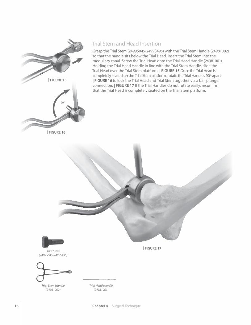
Trial Stem and Head Insertion Grasp the Trial Stem (2499S045-2499S495) with the Trial Stem Handle (24981002) so that the handle sits below the Trial Head. Insert the Trial Stem into the medullary canal. Screw the Trial Head onto the Trial Head Handle (24981001). Holding the Trial Head Handle in line with the Trial Stem Handle, slide the Trial Head over the Trial Stem platform. | FIGURE 15 Once the Trial Head is completely seated on the Trial Stem platform, rotate the Trial Handles 90º apart | FIGURE 16 to lock the Trial Head and Trial Stem together via a ball plunger connection. | FIGURE 17 If the Trial Handles do not rotate easily, reconfirm that the Trial Head is completely seated on the Trial Stem platform.
Chapter 4 Surgical Technique
90°
Trial Stem Handle(24981002)
| FIGURE 15
| FIGURE 16
| FIGURE 17
Trial Head Handle(24981001)
Trial Stem(2499S045-2400S495)
17Chapter 4 Surgical Technique
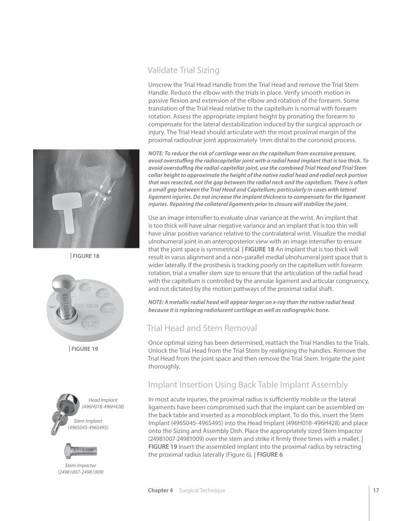
Validate Trial SizingUnscrew the Trial Head Handle from the Trial Head and remove the Trial Stem Handle. Reduce the elbow with the trials in place. Verify smooth motion in passive flexion and extension of the elbow and rotation of the forearm. Some translation of the Trial Head relative to the capitellum is normal with forearm rotation. Assess the appropriate implant height by pronating the forearm to compensate for the lateral destabilization induced by the surgical approach or injury. The Trial Head should articulate with the most proximal margin of the proximal radioulnar joint approximately 1mm distal to the coronoid process.
NOTE: To reduce the risk of cartilage wear on the capitellum from excessive pressure, avoid overstuffing the radiocapitellar joint with a radial head implant that is too thick. To avoid overstuffing the radial-capitellar joint, use the combined Trial Head and Trial Stem collar height to approximate the height of the native radial head and radial neck portion that was resected, not the gap between the radial neck and the capitellum. There is often a small gap between the Trial Head and Capitellum; particularly in cases with lateral ligament injuries. Do not increase the implant thickness to compensate for the ligament injuries. Repairing the collateral ligaments prior to closure will stabilize the joint.
Use an image intensifier to evaluate ulnar variance at the wrist. An implant that is too thick will have ulnar negative variance and an implant that is too thin will have ulnar positive variance relative to the contralateral wrist. Visualize the medial ulnohumeral joint in an anteroposterior view with an image intensifier to ensure that the joint space is symmetrical. | FIGURE 18 An implant that is too thick will result in varus alignment and a non-parallel medial ulnohumeral joint space that is wider laterally. If the prosthesis is tracking poorly on the capitellum with forearm rotation, trial a smaller stem size to ensure that the articulation of the radial head with the capitellum is controlled by the annular ligament and articular congruency, and not dictated by the motion pathways of the proximal radial shaft.
NOTE: A metallic radial head will appear larger on x-ray than the native radial head because it is replacing radiolucent cartilage as well as radiographic bone.
Trial Head and Stem Removal Once optimal sizing has been determined, reattach the Trial Handles to the Trials. Unlock the Trial Head from the Trial Stem by realigning the handles. Remove the Trial Head from the joint space and then remove the Trial Stem. Irrigate the joint thoroughly.
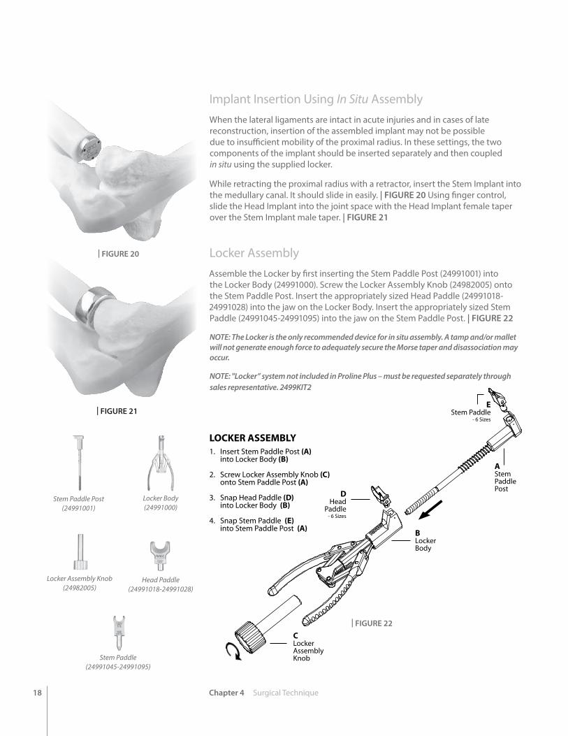
Implant Insertion Using Back Table Implant AssemblyIn most acute injuries, the proximal radius is sufficiently mobile or the lateral ligaments have been compromised such that the implant can be assembled on the back table and inserted as a monoblock implant. To do this, insert the Stem Implant (496S045-496S495) into the Head Implant (496H018-496H428) and place onto the Sizing and Assembly Dish. Place the appropriately sized Stem Impactor (24981007-24981009) over the stem and strike it firmly three times with a mallet. | FIGURE 19 Insert the assembled implant into the proximal radius by retracting the proximal radius laterally (Figure 6). | FIGURE 6
| FIGURE 18
| FIGURE 19
Stem Implant(496S045-496S495)
Head Implant(496H018-496H428)
Stem Impactor(24981007-24981009)
18 Chapter 4 Surgical Technique
LOCKER ASSEMBLY1. Insert Stem Paddle Post (A) into Locker Body (B)
2. Screw Locker Assembly Knob (C) onto Stem Paddle Post (A)
3. Snap Head Paddle (D) into Locker Body (B)
4. Snap Stem Paddle (E) into Stem Paddle Post (A)
EStem Paddle
- 6 Sizes
AStemPaddlePost
BLockerBody
CLockerAssemblyKnob
DHead
Paddle- 6 Sizes
| FIGURE 20
| FIGURE 21
| FIGURE 22
Stem Paddle Post(24991001)
Locker Body(24991000)
Locker Assembly Knob(24982005)
Head Paddle(24991018-24991028)
Stem Paddle(24991045-24991095)
Implant Insertion Using In Situ AssemblyWhen the lateral ligaments are intact in acute injuries and in cases of late reconstruction, insertion of the assembled implant may not be possible due to insufficient mobility of the proximal radius. In these settings, the two components of the implant should be inserted separately and then coupled in situ using the supplied locker.
While retracting the proximal radius with a retractor, insert the Stem Implant into the medullary canal. It should slide in easily. | FIGURE 20 Using finger control, slide the Head Implant into the joint space with the Head Implant female taper over the Stem Implant male taper. | FIGURE 21
Locker AssemblyAssemble the Locker by first inserting the Stem Paddle Post (24991001) into the Locker Body (24991000). Screw the Locker Assembly Knob (24982005) onto the Stem Paddle Post. Insert the appropriately sized Head Paddle (24991018-24991028) into the jaw on the Locker Body. Insert the appropriately sized Stem Paddle (24991045-24991095) into the jaw on the Stem Paddle Post. | FIGURE 22
NOTE: The Locker is the only recommended device for in situ assembly. A tamp and/or mallet will not generate enough force to adequately secure the Morse taper and disassociation may occur.
NOTE: "Locker” system not included in Proline Plus – must be requested separately through sales representative. 2499KIT2
19Chapter 4 Surgical Technique
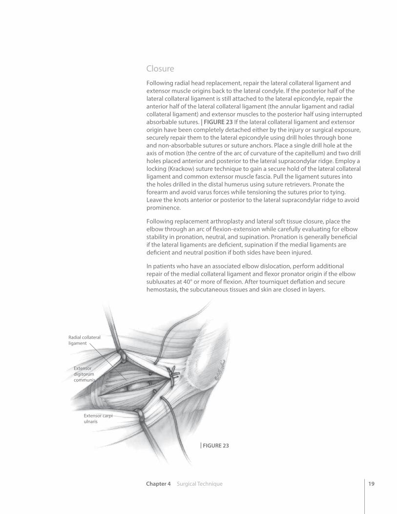
Radial collateral ligament
Extensor carpi ulnaris
Extensor digitorum communis
| FIGURE 23
Closure Following radial head replacement, repair the lateral collateral ligament and extensor muscle origins back to the lateral condyle. If the posterior half of the lateral collateral ligament is still attached to the lateral epicondyle, repair the anterior half of the lateral collateral ligament (the annular ligament and radial collateral ligament) and extensor muscles to the posterior half using interrupted absorbable sutures. | FIGURE 23 If the lateral collateral ligament and extensor origin have been completely detached either by the injury or surgical exposure, securely repair them to the lateral epicondyle using drill holes through bone and non-absorbable sutures or suture anchors. Place a single drill hole at the axis of motion (the centre of the arc of curvature of the capitellum) and two drill holes placed anterior and posterior to the lateral supracondylar ridge. Employ a locking (Krackow) suture technique to gain a secure hold of the lateral collateral ligament and common extensor muscle fascia. Pull the ligament sutures into the holes drilled in the distal humerus using suture retrievers. Pronate the forearm and avoid varus forces while tensioning the sutures prior to tying. Leave the knots anterior or posterior to the lateral supracondylar ridge to avoid prominence.
Following replacement arthroplasty and lateral soft tissue closure, place the elbow through an arc of flexion-extension while carefully evaluating for elbow stability in pronation, neutral, and supination. Pronation is generally beneficial if the lateral ligaments are deficient, supination if the medial ligaments are deficient and neutral position if both sides have been injured.
In patients who have an associated elbow dislocation, perform additional repair of the medial collateral ligament and flexor pronator origin if the elbow subluxates at 40° or more of flexion. After tourniquet deflation and secure hemostasis, the subcutaneous tissues and skin are closed in layers.

20 Chapter 4 Surgical Technique
Explant InformationIf the removal of the implant is required due to revision or failure of the device, the surgeon should contact the manufacturer using the contact information located on the back cover of this surgical technique to receive instructions for returning the explanted device to the manufacturer for investigation.
Postoperative ManagementThe recommended Post-Op Care varies primarily according to ligament competency.11,12
1. MCL and LCL Competent a. Splint elbow in extension and forearm in neutral b. Unrestricted active elbow motion permitted postoperatively c. Night-time resting extension splint may assist in gaining terminal extension
2. MCL Competent but LCL Incompetent a. Splint elbow at 90º with forearm pronated b. Active flexion-extension performed with forearm pronated c. Prosupination performed with elbow in flexion d. Avoid extension in supination for six weeks
3. MCL Incompetent and LCL Competent a. Splint elbow at 90º with forearm supinated b. Active flexion-extension performed with forearm supinated c. Prosupination performed with elbow in flexion d. Avoid extension in pronation for six weeks
4. MCL and LCL Incompetent a. Splint elbow at 90º with forearm in neutral b. Active flexion-extension performed with forearm in neutral rotation c. Prosupination performed with elbow in flexion d. Gradually allow increasing extension as stability improves with healing over six weeks
5. General Rehabilitation a. No passive stretching for six weeks to avoid heterotopic ossification. b. Strengthening exercises commence six to eight weeks postoperatively c. Night-time extension splint may be useful to regain terminal elbow extension. d. Prescribing indomethacin may reduce the incidence of heterotopic bone formation.
11. Armstrong AD, Dunning CE, Faber KJ, Duck TR, Johnson JA, King GJW: Rehabilitation of the medial collateral ligament-deficient elbow: An in vitro biomechanical study. J Hand Surg 25A:1051-1057, 2000.
12. Dunning CE, Zarzour ADS, Patterson SD, Johnson JA, King GJW: Muscle forces and pronation stabilize the lateral ligament deficient elbow. Clin Orthop & Related Research 388:118-124, 2001.
Lateral view at 2 years post-op
AP view at 2 years post-op
21Chapter 4 Surgical Technique
EVOLVE® Proline Plus Radial Head and Repair System
Radial Head and Neck PlatesPatient Preparation
Skin Incision
With the patient in either the supine or lateral decubitus position, make a posterior longitudinal skin incision just lateral to the tip of the olecranon. Elevate a full thickness lateral flap (fasciocutaneous) on the deep fascia to protect the cutaneous nerves. The posterior incision permits access to the medial side of the elbow if repair of the medial collateral ligament is necessary to restore elbow stability. It is also more cosmetic than a laterally based incision. In patients with isolated injuries to the radial head, a traditional lateral skin incision may be employed.
Direct Lateral Dissection
Pronate the forearm to move the posterior interosseous nerve more distal and medial during the surgical approach. Split the common extensor tendon longitudinally at the mid-aspect of the radial head and divide the underlying radial collateral and annular ligaments. Keep the dissection anterior to the lateral ulnar collateral ligament to prevent the development of posterolateral rotatory instability. If additional exposure is needed, elevate the humeral origin of the radial collateral ligament and the overlying extensor muscles anteriorly off the lateral epicondyle and lateral supracondylar ridge. In the unusual circumstance where further exposure is required, consider releasing the posterior component of the lateral collateral ligament (including the lateral ulnar collateral ligament). However, careful ligament repair is required at the end of the procedure in order to restore the varus and posterolateral rotatory stability of the elbow. In many circumstances, the radial head is easily visualized after opening the subcutaneous tissue due to avulsion of the lateral collateral ligament and common extensor muscles from the lateral epicondyle during the injury.
Sizing
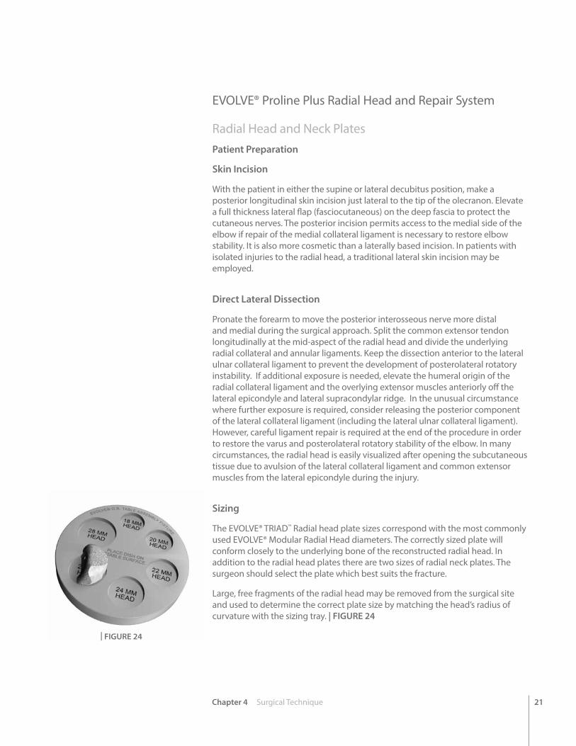
The EVOLVE® TRIAD™ Radial head plate sizes correspond with the most commonly used EVOLVE® Modular Radial Head diameters. The correctly sized plate will conform closely to the underlying bone of the reconstructed radial head. In addition to the radial head plates there are two sizes of radial neck plates. The surgeon should select the plate which best suits the fracture.
Large, free fragments of the radial head may be removed from the surgical site and used to determine the correct plate size by matching the head’s radius of curvature with the sizing tray. | FIGURE 24
| FIGURE 24
22 Chapter 4 Surgical Technique
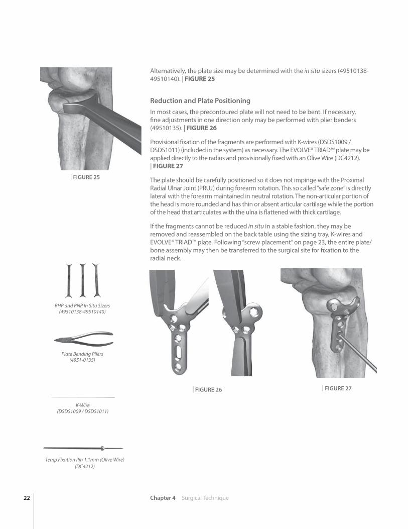
Alternatively, the plate size may be determined with the in situ sizers (49510138-49510140). | FIGURE 25
Reduction and Plate PositioningIn most cases, the precontoured plate will not need to be bent. If necessary, fine adjustments in one direction only may be performed with plier benders (49510135). | FIGURE 26
Provisional fixation of the fragments are performed with K-wires (DSDS1009 / DSDS1011) (included in the system) as necessary. The EVOLVE® TRIAD™ plate may be applied directly to the radius and provisionally fixed with an Olive Wire (DC4212). | FIGURE 27
The plate should be carefully positioned so it does not impinge with the Proximal Radial Ulnar Joint (PRUJ) during forearm rotation. This so called “safe zone” is directly lateral with the forearm maintained in neutral rotation. The non-articular portion of the head is more rounded and has thin or absent articular cartilage while the portion of the head that articulates with the ulna is flattened with thick cartilage.
If the fragments cannot be reduced in situ in a stable fashion, they may be removed and reassembled on the back table using the sizing tray, K-wires and EVOLVE® TRIAD™ plate. Following “screw placement” on page 23, the entire plate/bone assembly may then be transferred to the surgical site for fixation to the radial neck.
RHP and RNP In Situ Sizers (49510138-49510140)
| FIGURE 25
K-Wire(DSDS1009 / DSDS1011)
Temp Fixation Pin 1.1mm (Olive Wire) (DC4212)
Plate Bending Pliers(4951-0135)
| FIGURE 26 | FIGURE 27

23Chapter 4 Surgical Technique
Screw Preparation
The screw holes of the radial plates are designed to receive 2.0mm screws. The round holes can receive either 2.0mm ORTHOLOC® Mini Polyaxial Locking Screws or 2.0mm EVOLVE® TRIAD™ Non-Locking Bone Screws. The oval slots are used to allow for final adjustment of the plate position and are designed for non-locking screws only.
To use locking screws on-axis (or non-locking screws), the threaded locking drill guides should be used. | FIGURE 28
Screw the threaded guide into the desired hole. Using the 1.3mm drill (49510105), drill up to the opposing cortex. Care should be taken to avoid perforating the drill into PRUJ.
To prepare for off axis locking or non-locking screws, the variable angle or threaded Polyaxial Drill Guide (49510110) is used. With locking screws, care should be taken to avoid placing the screw more than 10 degrees off-axis. The Polyaxial Drill Guide may be used to constrain angling within the acceptable range. Remove the guides and measure for the length of the screw using the depth gauge. | FIGURE 29
Screw Placement
Screws are delivered to the operative site using the self-retaining Star-7 Driver (49510102). To pick up the screws, the driver is pressed firmly into the screw head while the screw is still in the caddy.
Alternatively, the screws may be picked up with the aid of the screw gripper and the standard non-self-retaining Star-7 driver. Screw length is verified with the gauge on the screw caddy. The plate should be securely attached to the radial head using as many 2.0mm screws as necessary.
If the plate and radial head fragments have been assembled ex vivo, the entire assembly is placed back in the surgical site and approximated to the shaft of the radius.
Locking screws should be tightened by hand until they lock firmly into the plate. | FIGURE 30
The elbow is taken through a full range of motion under fluoroscopic visualization to ensure that there is no impingement, impedance of motion or intra-articular screw penetration.
| FIGURE 28
| FIGURE 29
| FIGURE 30
Star-7 Driver(49510101)
Screw Gauge(Located in Screw Caddies)
1.3mm Drill(49510105)
Polyaxial Drill Guide 1.3mm(49510110)
24 Chapter 4 Surgical Technique
Postoperative ManagementThe wound is irrigated before closure. The radial collateral and annular ligaments and the common extensor origin split are carefully sutured. The competence of the Lateral Ulnar Collateral Ligament (LUCL) should be assessed and repaired if compromised by injury or the surgical approach. This can be accomplished with heavy sutures, drill holes or suture anchors. The skin is closed in layers. Postoperatively, the arm is started on early range of motion under the guidance of a trained therapist (if not precluded by other injuries of the elbow).
EVOLVE® TRIAD™ 2.5mm Cannulated Bone Screws
K-Wire Placement
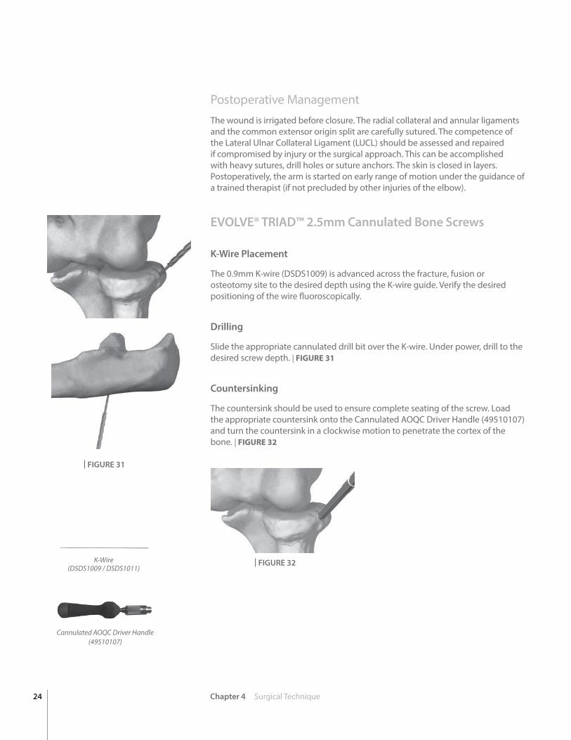
The 0.9mm K-wire (DSDS1009) is advanced across the fracture, fusion or osteotomy site to the desired depth using the K-wire guide. Verify the desired positioning of the wire fluoroscopically.
Drilling
Slide the appropriate cannulated drill bit over the K-wire. Under power, drill to the desired screw depth. | FIGURE 31
Countersinking
The countersink should be used to ensure complete seating of the screw. Load the appropriate countersink onto the Cannulated AOQC Driver Handle (49510107) and turn the countersink in a clockwise motion to penetrate the cortex of the bone. | FIGURE 32
Cannulated AOQC Driver Handle(49510107)
| FIGURE 31
| FIGURE 32K-Wire(DSDS1009 / DSDS1011)
Chapter 4 Surgical Technique 25
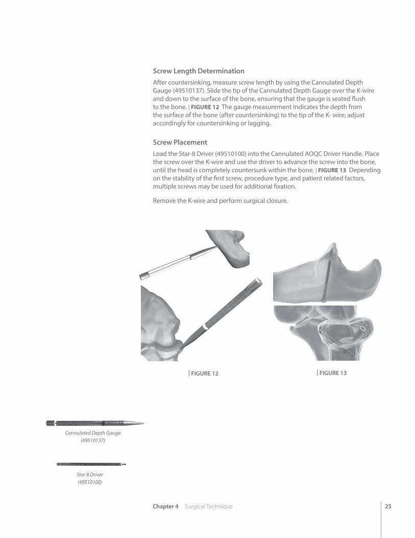
Screw Length DeterminationAfter countersinking, measure screw length by using the Cannulated Depth Gauge (49510137). Slide the tip of the Cannulated Depth Gauge over the K-wire and down to the surface of the bone, ensuring that the gauge is seated flush to the bone. | FIGURE 12 The gauge measurement indicates the depth from the surface of the bone (after countersinking) to the tip of the K- wire; adjust accordingly for countersinking or lagging.
Screw PlacementLoad the Star-8 Driver (49510100) into the Cannulated AOQC Driver Handle. Place the screw over the K-wire and use the driver to advance the screw into the bone, until the head is completely countersunk within the bone. | FIGURE 13 Depending on the stability of the first screw, procedure type, and patient related factors, multiple screws may be used for additional fixation.
Remove the K-wire and perform surgical closure.
Cannulated Depth Gauge(49510137)
Star 8 Driver(49510100)
| FIGURE 12 | FIGURE 13
26 Chapter 4 Surgical Technique
EVOLVE® TRIAD™ 2.0mm Bone Screws (outside plate)
In addition to the cannulated screws, 2.0mm bone screws may be used to capture fragments without the use of a plate.
DrillingUsing the proper diameter drill guide and drill bit, drill to the desired depth under power.
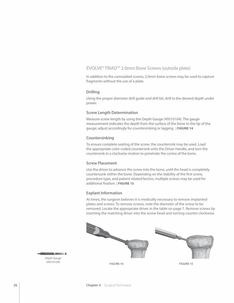
Screw Length DeterminationMeasure screw length by using the Depth Gauge (49510104). The gauge measurement indicates the depth from the surface of the bone to the tip of the gauge; adjust accordingly for countersinking or lagging. | FIGURE 14
CountersinkingTo ensure complete seating of the screw, the countersink may be used. Load the appropriate color coded countersink onto the Driver Handle, and turn the countersink in a clockwise motion to penetrate the cortex of the bone.
Screw PlacementUse the driver to advance the screw into the bone, until the head is completely countersunk within the bone. Depending on the stability of the first screw, procedure type, and patient related factors, multiple screws may be used for additional fixation. | FIGURE 15
Explant InformationAt times, the surgeon believes it is medically necessary to remove implanted plates and screws. To remove screws, note the diameter of the screw to be removed. Locate the appropriate driver in the table on page 7. Remove screws by inserting the matching driver into the screw head and turning counter clockwise.
FIGURE 14 FIGURE 15
Depth Gauge(49510104)
27Appendix A Ordering Information
App
endi
x A
Ordering Information
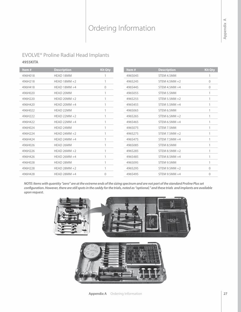
EVOLVE® Proline Radial Head Implants4955KITA
Item # Description Kit Qty
496H018 HEAD 18MM 1
496H218 HEAD 18MM +2 1
496H418 HEAD 18MM +4 0
496H020 HEAD 20MM 1
496H220 HEAD 20MM +2 1
496H420 HEAD 20MM +4 1
496H022 HEAD 22MM 1
496H222 HEAD 22MM +2 1
496H422 HEAD 22MM +4 1
496H024 HEAD 24MM 1
496H224 HEAD 24MM +2 1
496H424 HEAD 24MM +4 1
496H026 HEAD 26MM 1
496H226 HEAD 26MM +2 1
496H426 HEAD 26MM +4 1
496H028 HEAD 28MM 1
496H228 HEAD 28MM +2 1
496H428 HEAD 28MM +4 0
Item # Description Kit Qty
496S045 STEM 4.5MM 1
496S245 STEM 4.5MM +2 0
496S445 STEM 4.5MM +4 0
496S055 STEM 5.5MM 1
496S255 STEM 5.5MM +2 1
496S455 STEM 5.5MM +4 1
496S065 STEM 6.5MM 1
496S265 STEM 6.5MM +2 1
496S465 STEM 6.5MM +4 1
496S075 STEM 7.5MM 1
496S275 STEM 7.5MM +2 1
496S475 STEM 7.5MM +4 1
496S085 STEM 8.5MM 1
496S285 STEM 8.5MM +2 1
496S485 STEM 8.5MM +4 1
496S095 STEM 9.5MM 1
496S295 STEM 9.5MM +2 0
496S495 STEM 9.5MM +4 0
NOTE: Items with quantity “zero” are at the extreme ends of the sizing spectrum and are not part of the standard Proline Plus set configuration. However, there are still spots in the caddy for the trials, noted as “optional,” and these trials and implants are available upon request.
28 Appendix A Ordering Information
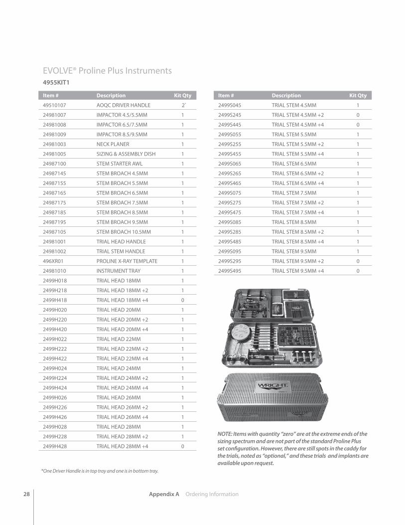
EVOLVE® Proline Plus Instruments4955KIT1
Item # Description Kit Qty
49510107 AOQC DRIVER HANDLE 2*
24981007 IMPACTOR 4.5/5.5MM 1
24981008 IMPACTOR 6.5/7.5MM 1
24981009 IMPACTOR 8.5/9.5MM 1
24981003 NECK PLANER 1
24981005 SIZING & ASSEMBLY DISH 1
24987100 STEM STARTER AWL 1
24987145 STEM BROACH 4.5MM 1
24987155 STEM BROACH 5.5MM 1
24987165 STEM BROACH 6.5MM 1
24987175 STEM BROACH 7.5MM 1
24987185 STEM BROACH 8.5MM 1
24987195 STEM BROACH 9.5MM 1
24987105 STEM BROACH 10.5MM 1
24981001 TRIAL HEAD HANDLE 1
24981002 TRIAL STEM HANDLE 1
496XR01 PROLINE X-RAY TEMPLATE 1
24981010 INSTRUMENT TRAY 1
2499H018 TRIAL HEAD 18MM 1
2499H218 TRIAL HEAD 18MM +2 1
2499H418 TRIAL HEAD 18MM +4 0
2499H020 TRIAL HEAD 20MM 1
2499H220 TRIAL HEAD 20MM +2 1
2499H420 TRIAL HEAD 20MM +4 1
2499H022 TRIAL HEAD 22MM 1
2499H222 TRIAL HEAD 22MM +2 1
2499H422 TRIAL HEAD 22MM +4 1
2499H024 TRIAL HEAD 24MM 1
2499H224 TRIAL HEAD 24MM +2 1
2499H424 TRIAL HEAD 24MM +4 1
2499H026 TRIAL HEAD 26MM 1
2499H226 TRIAL HEAD 26MM +2 1
2499H426 TRIAL HEAD 26MM +4 1
2499H028 TRIAL HEAD 28MM 1
2499H228 TRIAL HEAD 28MM +2 1
2499H428 TRIAL HEAD 28MM +4 0
Item # Description Kit Qty
2499S045 TRIAL STEM 4.5MM 1
2499S245 TRIAL STEM 4.5MM +2 0
2499S445 TRIAL STEM 4.5MM +4 0
2499S055 TRIAL STEM 5.5MM 1
2499S255 TRIAL STEM 5.5MM +2 1
2499S455 TRIAL STEM 5.5MM +4 1
2499S065 TRIAL STEM 6.5MM 1
2499S265 TRIAL STEM 6.5MM +2 1
2499S465 TRIAL STEM 6.5MM +4 1
2499S075 TRIAL STEM 7.5MM 1
2499S275 TRIAL STEM 7.5MM +2 1
2499S475 TRIAL STEM 7.5MM +4 1
2499S085 TRIAL STEM 8.5MM 1
2499S285 TRIAL STEM 8.5MM +2 1
2499S485 TRIAL STEM 8.5MM +4 1
2499S095 TRIAL STEM 9.5MM 1
2499S295 TRIAL STEM 9.5MM +2 0
2499S495 TRIAL STEM 9.5MM +4 0
NOTE: Items with quantity “zero” are at the extreme ends of the sizing spectrum and are not part of the standard Proline Plus set configuration. However, there are still spots in the caddy for the trials, noted as “optional,” and these trials and implants are available upon request.
*One Driver Handle is in top tray and one is in bottom tray.
Appendix A Ordering Information 29
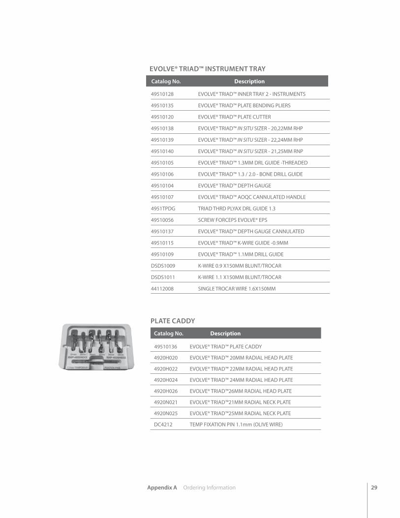
EVOLVE® TRIAD™ INSTRUMENT TRAY
Catalog No. Description
49510128 EVOLVE® TRIAD™ INNER TRAY 2 - INSTRUMENTS
49510135 EVOLVE® TRIAD™ PLATE BENDING PLIERS
49510120 EVOLVE® TRIAD™ PLATE CUTTER
49510138 EVOLVE® TRIAD™ IN SITU SIZER - 20,22MM RHP
49510139 EVOLVE® TRIAD™ IN SITU SIZER - 22,24MM RHP
49510140 EVOLVE® TRIAD™ IN SITU SIZER - 21,25MM RNP
49510105 EVOLVE® TRIAD™ 1.3MM DRL GUIDE -THREADED
49510106 EVOLVE® TRIAD™ 1.3 / 2.0 - BONE DRILL GUIDE
49510104 EVOLVE® TRIAD™ DEPTH GAUGE
49510107 EVOLVE® TRIAD™ AOQC CANNULATED HANDLE
4951TPDG TRIAD THRD PLYAX DRL GUIDE 1.3
49510056 SCREW FORCEPS EVOLVE® EPS
49510137 EVOLVE® TRIAD™ DEPTH GAUGE CANNULATED
49510115 EVOLVE® TRIAD™ K-WIRE GUIDE -0.9MM
49510109 EVOLVE® TRIAD™ 1.1MM DRILL GUIDE
DSDS1009 K-WIRE 0.9 X150MM BLUNT/TROCAR
DSDS1011 K-WIRE 1.1 X150MM BLUNT/TROCAR
44112008 SINGLE TROCAR WIRE 1.6X150MM
PLATE CADDY
Catalog No. Description 49510136 EVOLVE® TRIAD™ PLATE CADDY
4920H020 EVOLVE® TRIAD™ 20MM RADIAL HEAD PLATE
4920H022 EVOLVE® TRIAD™ 22MM RADIAL HEAD PLATE
4920H024 EVOLVE® TRIAD™ 24MM RADIAL HEAD PLATE
4920H026 EVOLVE® TRIAD™26MM RADIAL HEAD PLATE
4920N021 EVOLVE® TRIAD™21MM RADIAL NECK PLATE
4920N025 EVOLVE® TRIAD™25MM RADIAL NECK PLATE
DC4212 TEMP FIXATION PIN 1.1mm (OLIVE WIRE)
30 Appendix A Ordering Information
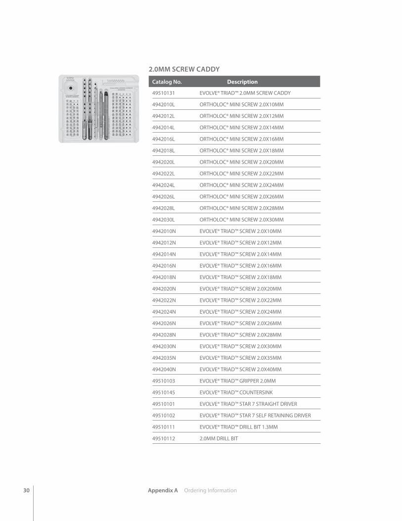
2.0MM SCREW CADDY
Catalog No. Description
49510131 EVOLVE® TRIAD™ 2.0MM SCREW CADDY
4942010L ORTHOLOC® MINI SCREW 2.0X10MM
4942012L ORTHOLOC® MINI SCREW 2.0X12MM
4942014L ORTHOLOC® MINI SCREW 2.0X14MM
4942016L ORTHOLOC® MINI SCREW 2.0X16MM
4942018L ORTHOLOC® MINI SCREW 2.0X18MM
4942020L ORTHOLOC® MINI SCREW 2.0X20MM
4942022L ORTHOLOC® MINI SCREW 2.0X22MM
4942024L ORTHOLOC® MINI SCREW 2.0X24MM
4942026L ORTHOLOC® MINI SCREW 2.0X26MM
4942028L ORTHOLOC® MINI SCREW 2.0X28MM
4942030L ORTHOLOC® MINI SCREW 2.0X30MM
4942010N EVOLVE® TRIAD™ SCREW 2.0X10MM
4942012N EVOLVE® TRIAD™ SCREW 2.0X12MM
4942014N EVOLVE® TRIAD™ SCREW 2.0X14MM
4942016N EVOLVE® TRIAD™ SCREW 2.0X16MM
4942018N EVOLVE® TRIAD™ SCREW 2.0X18MM
4942020N EVOLVE® TRIAD™ SCREW 2.0X20MM
4942022N EVOLVE® TRIAD™ SCREW 2.0X22MM
4942024N EVOLVE® TRIAD™ SCREW 2.0X24MM
4942026N EVOLVE® TRIAD™ SCREW 2.0X26MM
4942028N EVOLVE® TRIAD™ SCREW 2.0X28MM
4942030N EVOLVE® TRIAD™ SCREW 2.0X30MM
4942035N EVOLVE® TRIAD™ SCREW 2.0X35MM
4942040N EVOLVE® TRIAD™ SCREW 2.0X40MM
49510103 EVOLVE® TRIAD™ GRIPPER 2.0MM
49510145 EVOLVE® TRIAD™ COUNTERSINK
49510101 EVOLVE® TRIAD™ STAR 7 STRAIGHT DRIVER
49510102 EVOLVE® TRIAD™ STAR 7 SELF RETAINING DRIVER
49510111 EVOLVE® TRIAD™ DRILL BIT 1.3MM
49510112 2.0MM DRILL BIT
Appendix A Ordering Information 31
2.5MM SCREW CADDY
Catalog No. Description
49510132 EVOLVE® TRIAD™ 2.5MM SCREW CADDY
4942510CH EVOLVE® TRIAD™ CANNULATED SCREW 2.5X10MM (FULLY THREADED)
4942512CH EVOLVE® TRIAD™ CANNULATED SCREW 2.5X12MM (FULLY THREADED)
4942514CH EVOLVE® TRIAD™ CANNULATED SCREW 2.5X14MM (FULLY THREADED)
4942516CH EVOLVE® TRIAD™ CANNULATED SCREW 2.5X16MM (FULLY THREADED)
4942518CH EVOLVE® TRIAD™ CANNULATED SCREW 2.5X18MM (FULLY THREADED)
4942520CH EVOLVE® TRIAD™ CANNULATED SCREW 2.5X20MM (FULLY THREADED)
4942522CH EVOLVE® TRIAD™ CANNULATED SCREW 2.5X22MM (FULLY THREADED)
4942524CH EVOLVE® TRIAD™ CANNULATED SCREW 2.5X24MM (FULLY THREADED)
4942526CH EVOLVE® TRIAD™ CANNULATED SCREW 2.5X26MM (FULLY THREADED)
4942528CH EVOLVE® TRIAD™ CANNULATED SCREW 2.5X28MM (FULLY THREADED)
4942530CH EVOLVE® TRIAD™ CANNULATED SCREW 2.5X30MM (FULLY THREADED)
4942532CH EVOLVE® TRIAD™ CANNULATED SCREW 2.5X32MM (FULLY THREADED)
4942534CH EVOLVE® TRIAD™ CANNULATED SCREW 2.5X34MM (FULLY THREADED)
4942536CH EVOLVE® TRIAD™ CANNULATED SCREW 2.5X36MM (FULLY THREADED)
4942538CH EVOLVE® TRIAD™ CANNULATED SCREW 2.5X38MM (FULLY THREADED)
4942540CH EVOLVE® TRIAD™ CANNULATED SCREW 2.5X40MM (FULLY THREADED)
4942542CH EVOLVE® TRIAD™ CANNULATED SCREW 2.5X42MM (FULLY THREADED)
4942544CH EVOLVE® TRIAD™ CANNULATED SCREW 2.5X44MM (FULLY THREADED)
4942546CH EVOLVE® TRIAD™ CANNULATED SCREW 2.5X46MM (FULLY THREADED)
4942548CH EVOLVE® TRIAD™ CANNULATED SCREW2.5X48MM (FULLY THREADED)
4942550CH EVOLVE® TRIAD™ CANNULATED SCREW2.5X50MM (FULLY THREADED)
49510114 EVOLVE® TRIAD™ COUNTERSINK FOR 2.5MM SCREWS
DSDS0001 CLEANING STYLET 0.9MM
49510144 EVOLVE® TRIAD™ STAR 8 CANNULATED DRIVER
49510143 EVOLVE® TRIAD™ DRILL BIT 2.0MM
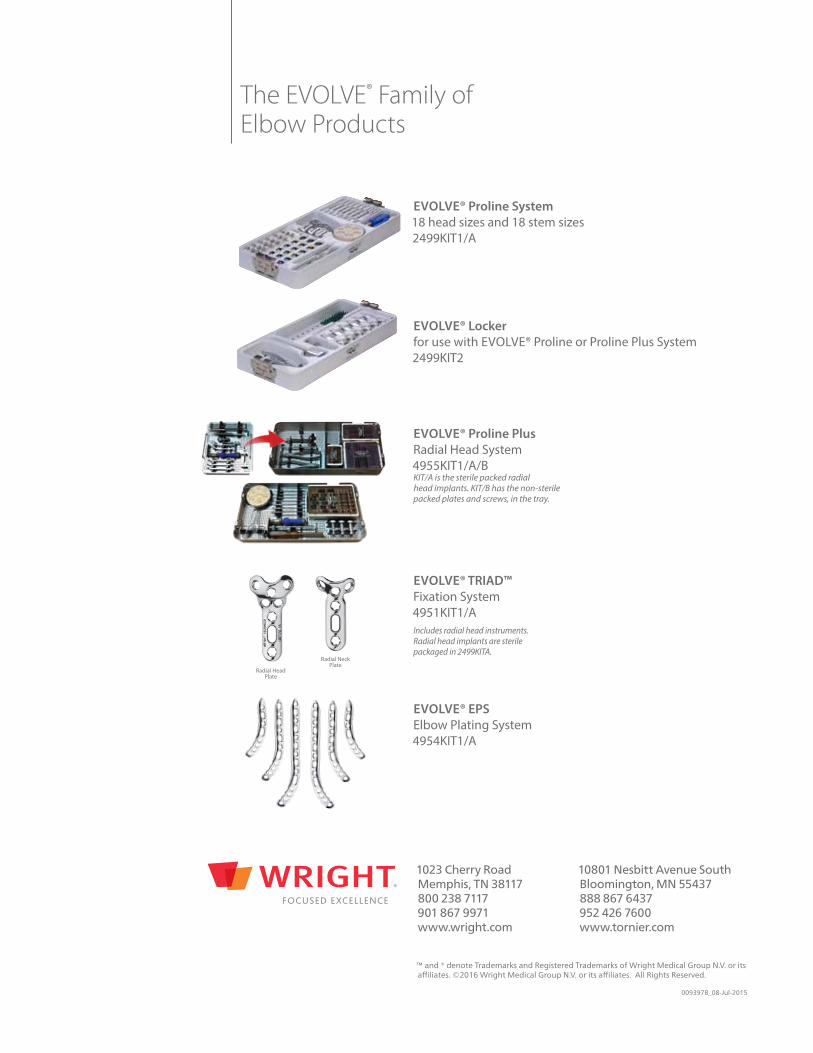
EVOLVE® Proline System18 head sizes and 18 stem sizes2499KIT1/A
EVOLVE® Lockerfor use with EVOLVE® Proline or Proline Plus System 2499KIT2
EVOLVE® Proline PlusRadial Head System4955KIT1/A/B KIT/A is the sterile packed radial head implants. KIT/B has the non-sterile packed plates and screws, in the tray.
EVOLVE® TRIAD™Fixation System 4951KIT1/AIncludes radial head instruments.Radial head implants are sterilepackaged in 2499KITA.
EVOLVE® EPSElbow Plating System 4954KIT1/A
The EVOLVE® Family of Elbow Products
Radial HeadPlate
Radial NeckPlate
™ and ® denote Trademarks and Registered Trademarks of Wright Medical Group N.V. or its affiliates. ©2016 Wright Medical Group N.V. or its affiliates. All Rights Reserved. 009397B_08-Jul-2015
1023 Cherry RoadMemphis, TN 38117800 238 7117901 867 9971www.wright.com
10801 Nesbitt Avenue SouthBloomington, MN 55437888 867 6437952 426 7600www.tornier.com