Embed Size (px)
Citation preview

Exam 3/Final Review

Exam 3
Mean adjusted score: 62% ( C ) Correct multiple choice answers:
1. D2. B3. E4. A5. E6. C7. A8. B or C9. E10. B11. C
Problem 4
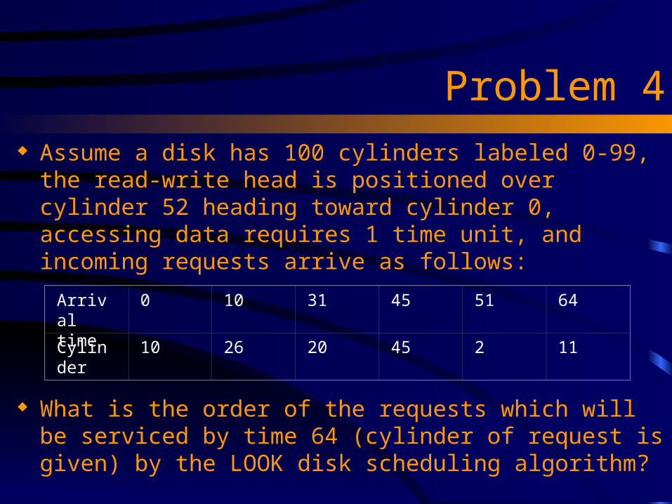
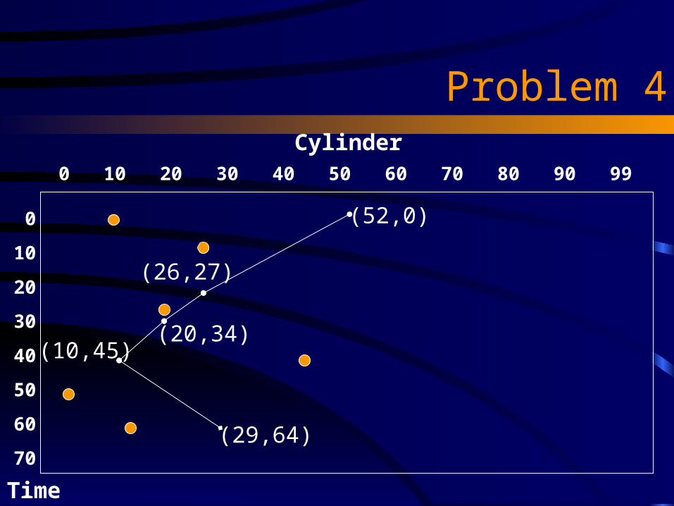
Assume a disk has 100 cylinders labeled 0-99, the read-write head is positioned over cylinder 52 heading toward cylinder 0, accessing data requires 1 time unit, and incoming requests arrive as follows:
What is the order of the requests which will be serviced by time 64 (cylinder of request is given) by the LOOK disk scheduling algorithm?
Arrival time
0 10 31 45 51 64
Cylinder 10 26 20 45 2 11
Problem 4
0 10 20 30 40 50 60 70 80 90 99
0
10
20
30
40
50
60
70
(52,0)
(26,27)
(20,34)(10,45)
(29,64)
Time
Cylinder

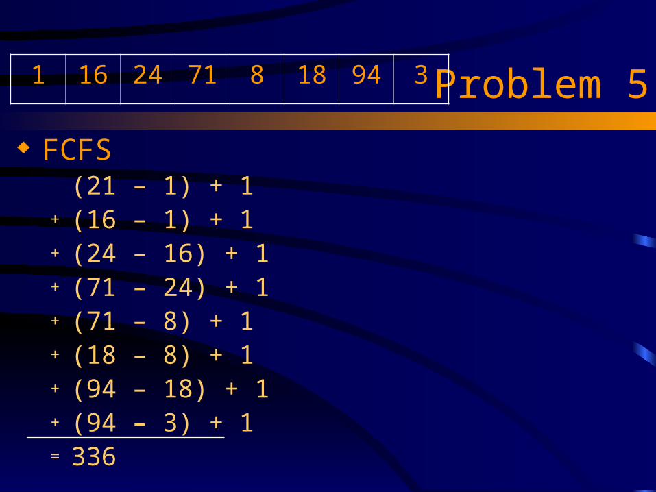
Problem 5 Assume a disk has 100 cylinders labeled 0-99, the read-
write head is positioned over cylinder 21 heading toward cylinder 0, accessing data requires 1 time unit, and pending requests are as follows: 1, 16, 24, 71, 8, 18, 94, 3 (listed in order of arrival). Which disk scheduling algorithm will finish servicing the requests first? SSTF (break tie by moving toward cylinder 0.) LOOK FCFS C-Scan None of the above: there is a tie.

Problem 5
SSTF (21 – 18) + 1 Tie between 18 and 24, move to 18+ (18 – 16) + 1+ (16 – 8) + 1 Tie between 8 and 24, move to 8+ (8 – 3) + 1+ (3 – 1) + 1+ (24 – 1) + 1+ (71 – 24) + 1+ (94 – 71) + 1= 121
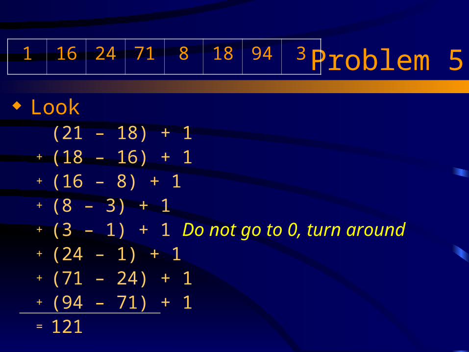
1 16 24 71 8 18 94 3
Problem 5
Look (21 – 18) + 1+ (18 – 16) + 1+ (16 – 8) + 1+ (8 – 3) + 1+ (3 – 1) + 1 Do not go to 0, turn around+ (24 – 1) + 1+ (71 – 24) + 1+ (94 – 71) + 1= 121
1 16 24 71 8 18 94 3
Problem 5
FCFS (21 – 1) + 1+ (16 – 1) + 1+ (24 – 16) + 1+ (71 – 24) + 1+ (71 – 8) + 1 + (18 – 8) + 1+ (94 – 18) + 1+ (94 – 3) + 1= 336
1 16 24 71 8 18 94 3

Problem 5 C-Scan (read/write heading toward zero)
(21 – 18) + 1+ (18 – 16) + 1+ (16 – 8) + 1+ (8 – 3) + 1+ (3 – 1) + 1+ (1 – 0)+ (99 – 0)+ (99 – 94) + 1+ (94 – 71) + 1+ (71 – 24) + 1+ (24 – 1) + 1= 221
1 16 24 71 8 18 94 3

Final Exam Review
More disk scheduling Exponential moving average for predicting next
burst Banker’s algorithm

SSTF (static) Assume the R/W heads hold
stationary when there is no pending request, and that seek decisions are never reversed on new arrival
What is the total time to service all requests?
(28 – 3) + 1 + (16 – 3) +1 +(58–16) + 1 + (98 – 58) + 1 +(98 – 71) + 1 + (71 – 12) + 1 +(56 – 12) + 1 = 256
Arrival Time Cylinder
0 3
4 16
20 58
51 98
113 71
131 12
185 56

SSTF (static)
3 12 16 28 56 58 71 980102030405060708090100110120130140150160
0
26
83
124
152
Arrival Time Cylinder
0 3
4 16
20 58
51 98
113 71
131 12
185 56
40

SSTF (static)
3 12 16 28 56 58 71 98170180190200210220230240250260270280290300310320330
212
256
Arrival Time Cylinder
0 3
4 16
20 58
51 98
113 71
131 12
185 56

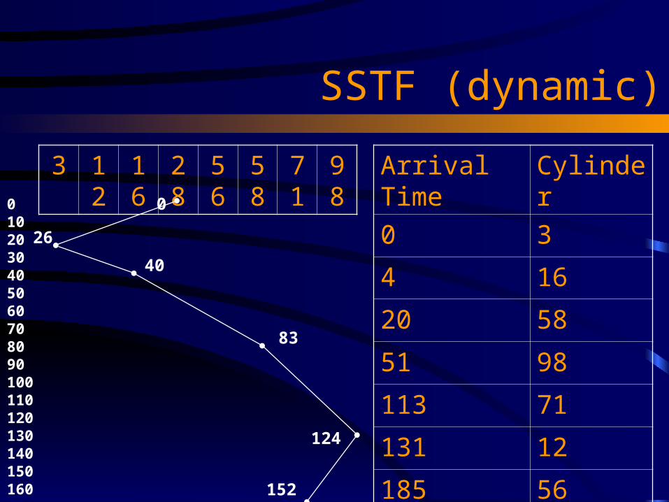
SSTF (dynamic) Assume the R/W heads continue
moving toward cylinder 50 when there is no pending request, and that seek decisions can be changed dynamically
What is the total time to service all requests?
(28 – 3) + 1 + (16 – 3) +1 +
(58–16) + 1 + (98 – 58) + 1 +
(98 – 71) + 1 + (71 – 48) +
(56 – 48 ) + 1 + (56 – 12) + 1 = 229
Arrival Time Cylinder
0 3
4 16
20 58
51 98
113 71
131 12
185 56
SSTF (dynamic)
3 12 16 28 56 58 71 980102030405060708090100110120130140150160
0
26
83
124
152
Arrival Time Cylinder
0 3
4 16
20 58
51 98
113 71
131 12
185 56
40

SSTF (dynamic)
3 12 16 28 56 58 71 98170180190200210220230240250260270280290300310320330
184
229
Arrival Time Cylinder
0 3
4 16
20 58
51 98
113 71
131 12
185 56

Page Replacement

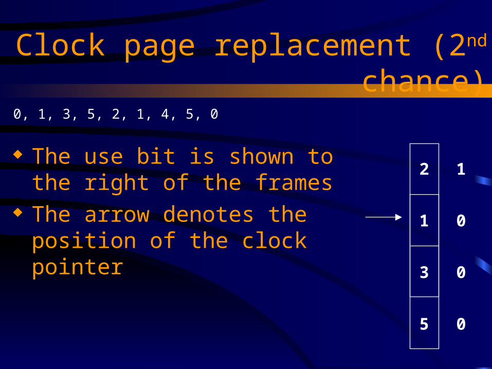
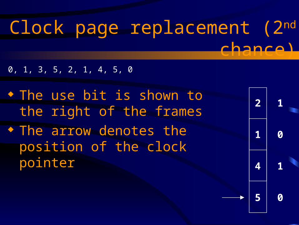
Clock page replacement (2nd chance)
The use bit is shown to the right of the frames
The arrow denotes the position of the clock pointer
0, 1, 3, 5, 2, 1, 4, 5, 0
0
1
3
5
1
1
1
1
Clock page replacement (2nd chance)
The use bit is shown to the right of the frames
The arrow denotes the position of the clock pointer
0, 1, 3, 5, 2, 1, 4, 5, 0
2
1
3
5
1
0
0
0

Clock page replacement (2nd chance)
The use bit is shown to the right of the frames
The arrow denotes the position of the clock pointer
0, 1, 3, 5, 2, 1, 4, 5, 0
2
1
3
5
1
1
0
0
Clock page replacement (2nd chance)
The use bit is shown to the right of the frames
The arrow denotes the position of the clock pointer
0, 1, 3, 5, 2, 1, 4, 5, 0
2
1
4
5
1
0
1
0

Clock page replacement (2nd chance)
The use bit is shown to the right of the frames
The arrow denotes the position of the clock pointer
0, 1, 3, 5, 2, 1, 4, 5, 0
2
1
4
5
1
0
1
1

Clock page replacement (2nd chance)
The use bit is shown to the right of the frames
The arrow denotes the position of the clock pointer
0, 1, 3, 5, 2, 1, 4, 5, 0
2
0
4
5
0
1
1
0
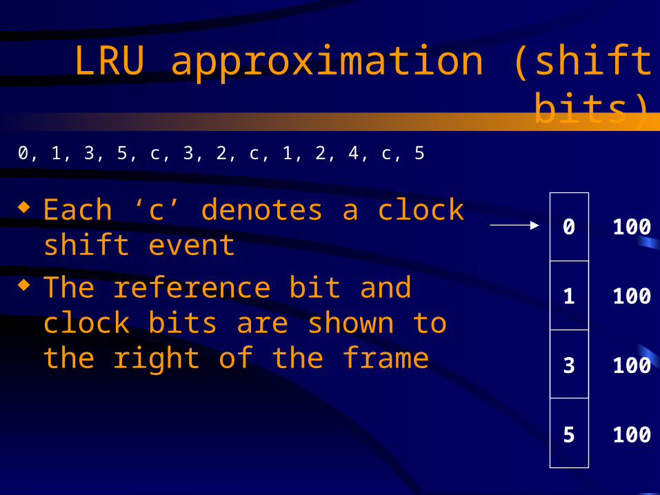
LRU approximation (shift bits)
Each ‘c’ denotes a clock shift event The reference bit and clock bits are
shown to the right of the frame
0, 1, 3, 5, c, 3, 2, c, 1, 2, 4, c, 5
0
1
3
5
100
100
100
100

LRU approximation (shift bits)
Each ‘c’ denotes a clock shift event The reference bit and clock bits are
shown to the right of the frame
0, 1, 3, 5, c, 3, 2, c, 1, 2, 4, c, 5
0
1
3
5
010
010
110
010

LRU approximation (shift bits)
Each ‘c’ denotes a clock shift event The reference bit and clock bits are
shown to the right of the frame
0, 1, 3, 5, c, 3, 2, c, 1, 2, 4, c, 5
2
1
3
5
100
010
110
010

LRU approximation (shift bits)
Each ‘c’ denotes a clock shift event The reference bit and clock bits are
shown to the right of the frame
0, 1, 3, 5, c, 3, 2, c, 1, 2, 4, c, 5
2
1
3
5
010
001
011
001

LRU approximation (shift bits)
Each ‘c’ denotes a clock shift event The reference bit and clock bits are
shown to the right of the frame
0, 1, 3, 5, c, 3, 2, c, 1, 2, 4, c, 5
2
1
3
5
110
101
011
001

LRU approximation (shift bits)
Each ‘c’ denotes a clock shift event The reference bit and clock bits are
shown to the right of the frame
0, 1, 3, 5, c, 3, 2, c, 1, 2, 4, c, 5
2
1
3
4
110
101
011
100

LRU approximation (shift bits)
Each ‘c’ denotes a clock shift event The reference bit and clock bits are
shown to the right of the frame
0, 1, 3, 5, c, 3, 2, c, 1, 2, 4, c, 5
2
1
3
4
011
010
001
010
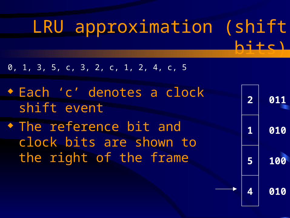
LRU approximation (shift bits)
Each ‘c’ denotes a clock shift event The reference bit and clock bits are
shown to the right of the frame
0, 1, 3, 5, c, 3, 2, c, 1, 2, 4, c, 5
2
1
5
4
011
010
100
010

Banker’s Algorithm
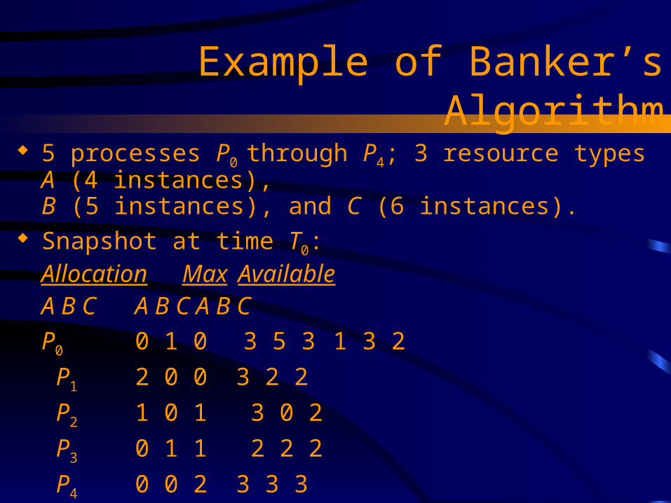
Example of Banker’s Algorithm 5 processes P0 through P4; 3 resource types A (4 instances),
B (5 instances), and C (6 instances). Snapshot at time T0:
Allocation Max AvailableA B C A B C A B C
P0 0 1 0 3 5 3 1 3 2
P1 2 0 0 3 2 2
P2 1 0 1 3 0 2
P3 0 1 1 2 2 2
P4 0 0 2 3 3 3

Example of Banker’s Algorithm Is the system currently safe? Suppose a request for <1, 1, 1> came from P1.
Allocation Max AvailableA B C A B C A B C
P0 0 1 0 3 5 3 1 3 2
P1 2 0 0 3 2 2
P2 1 0 1 3 0 2
P3 0 1 1 2 2 2
P4 0 0 2 3 3 3
NeedA B C3 4 3 1 2 2 2 0 1 2 1 13 3 1
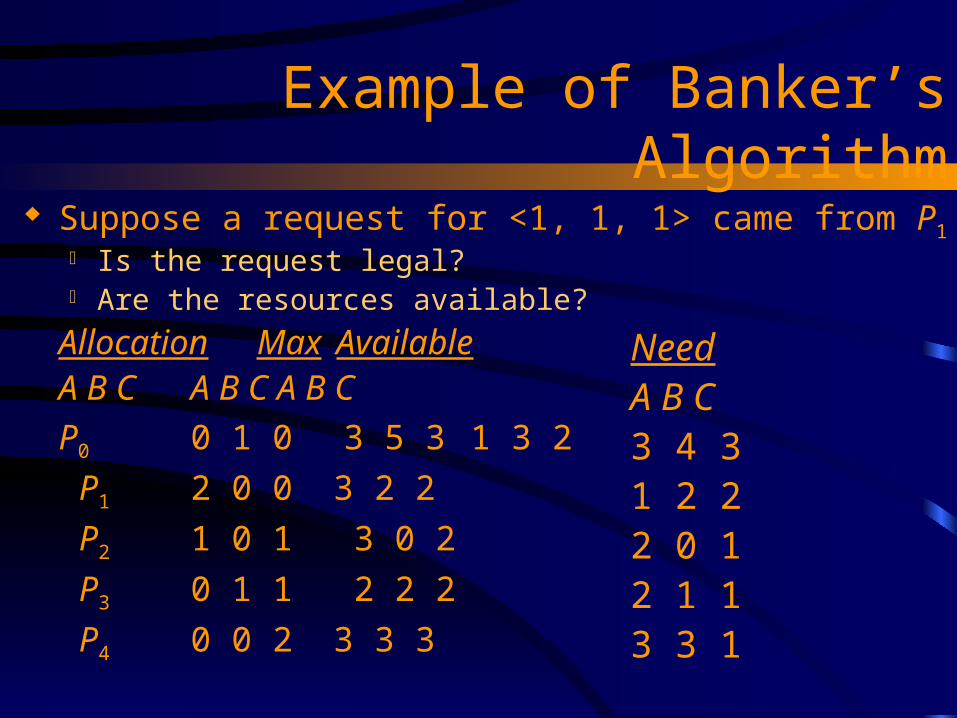
Example of Banker’s Algorithm Suppose a request for <1, 1, 1> came from P1
Is the request legal? Are the resources available?
Allocation Max AvailableA B C A B C A B C
P0 0 1 0 3 5 3 1 3 2
P1 2 0 0 3 2 2
P2 1 0 1 3 0 2
P3 0 1 1 2 2 2
P4 0 0 2 3 3 3
NeedA B C3 4 3 1 2 2 2 0 1 2 1 13 3 1
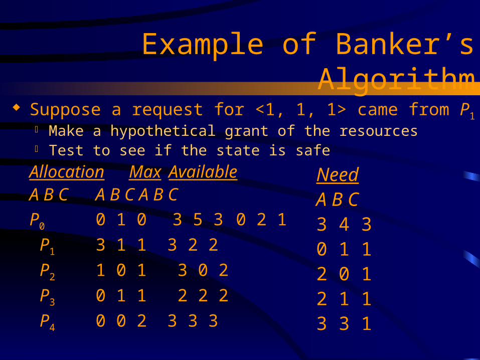
Example of Banker’s Algorithm Suppose a request for <1, 1, 1> came from P1
Make a hypothetical grant of the resources Test to see if the state is safe
Allocation Max AvailableA B C A B C A B C
P0 0 1 0 3 5 3 0 2 1
P1 3 1 1 3 2 2
P2 1 0 1 3 0 2
P3 0 1 1 2 2 2
P4 0 0 2 3 3 3
NeedA B C3 4 3 0 1 1 2 0 1 2 1 13 3 1

Example of Banker’s Algorithm Suppose a request for <1, 1, 1> came from P1
Make a hypothetical grant of the resources Test to see if the state is safe
Allocation Max WorkA B C A B C A B C
P0 0 1 0 3 5 3 0 2 1
P1 3 1 1 3 2 2
P2 1 0 1 3 0 2
P3 0 1 1 2 2 2
P4 0 0 2 3 3 3
NeedA B C3 4 3 0 1 1 2 0 1 2 1 13 3 1
P1

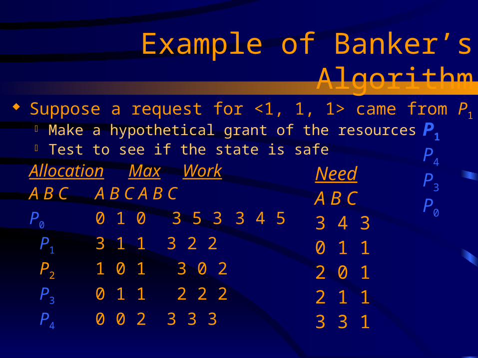
Example of Banker’s Algorithm Suppose a request for <1, 1, 1> came from P1
Make a hypothetical grant of the resources Test to see if the state is safe
Allocation Max WorkA B C A B C A B C
P0 0 1 0 3 5 3 3 3 2
P1 3 1 1 3 2 2
P2 1 0 1 3 0 2
P3 0 1 1 2 2 2
P4 0 0 2 3 3 3
NeedA B C3 4 3 0 1 1 2 0 1 2 1 13 3 1
P1

Example of Banker’s Algorithm Suppose a request for <1, 1, 1> came from P1
Make a hypothetical grant of the resources Test to see if the state is safe
Allocation Max WorkA B C A B C A B C
P0 0 1 0 3 5 3 3 3 4
P1 3 1 1 3 2 2
P2 1 0 1 3 0 2
P3 0 1 1 2 2 2
P4 0 0 2 3 3 3
NeedA B C3 4 3 0 1 1 2 0 1 2 1 13 3 1
P1
P4
P3
Example of Banker’s Algorithm Suppose a request for <1, 1, 1> came from P1
Make a hypothetical grant of the resources Test to see if the state is safe
Allocation Max WorkA B C A B C A B C
P0 0 1 0 3 5 3 3 4 5
P1 3 1 1 3 2 2
P2 1 0 1 3 0 2
P3 0 1 1 2 2 2
P4 0 0 2 3 3 3
NeedA B C3 4 3 0 1 1 2 0 1 2 1 13 3 1
P1
P4
P3
P0
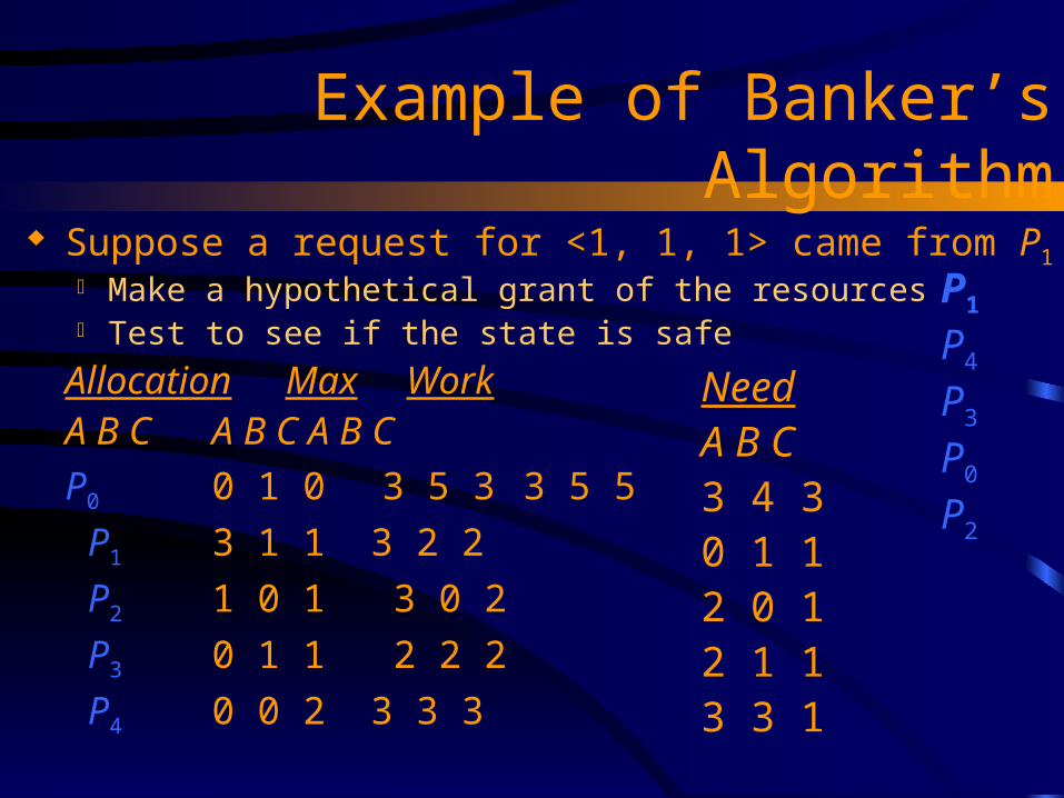
Example of Banker’s Algorithm Suppose a request for <1, 1, 1> came from P1
Make a hypothetical grant of the resources Test to see if the state is safe
Allocation Max WorkA B C A B C A B C
P0 0 1 0 3 5 3 3 5 5
P1 3 1 1 3 2 2
P2 1 0 1 3 0 2
P3 0 1 1 2 2 2
P4 0 0 2 3 3 3
NeedA B C3 4 3 0 1 1 2 0 1 2 1 13 3 1
P1
P4
P3
P0
P2

Example of Banker’s Algorithm Suppose a request for <1, 1, 1> came from P1
Make a hypothetical grant of the resources Test to see if the state is safe
Allocation Max WorkA B C A B C A B C
P0 0 1 0 3 5 3 4 5 6
P1 3 1 1 3 2 2
P2 1 0 1 3 0 2
P3 0 1 1 2 2 2
P4 0 0 2 3 3 3
NeedA B C3 4 3 0 1 1 2 0 1 2 1 13 3 1
P1
P4
P3
P0
P2

Detection Algorithm
1.Let Work and Finish be vectors of length m and n, respectively Initialize:(a) Work :- Available
(b) For i = 1,2, …, n, if Allocationi 0, then Finish[i] := false;otherwise, Finish[i] := true.
2.Find an index i such that both:(a) Finish[i] = false
(b) Requesti Work
If no such i exists, go to step 4.
Detection Algorithm
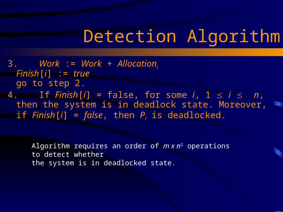
3. Work := Work + Allocationi
Finish[i] := truego to step 2.
4. If Finish[i] = false, for some i, 1 i n, then the system is in deadlock state. Moreover, if Finish[i] = false, then Pi is deadlocked.
Algorithm requires an order of m x n2 operations to detect whether the system is in deadlocked state.
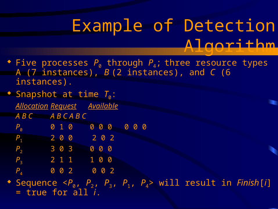
Example of Detection Algorithm Five processes P0 through P4; three resource types
A (7 instances), B (2 instances), and C (6 instances). Snapshot at time T0:
Allocation Request AvailableA B C A B C A B C
P0 0 1 0 0 0 0 0 0 0
P1 2 0 0 2 0 2
P2 3 0 3 0 0 0
P3 2 1 1 1 0 0
P4 0 0 2 0 0 2 Sequence <P0, P2, P3, P1, P4> will result in Finish[i] = true for
all i.

Example (Cont.) P2 requests an additional instance of type C.
RequestA B C
P0 0 0 0
P1 2 0 1
P2 0 0 1
P3 1 0 0
P4 0 0 2 State of system?
Can reclaim resources held by process P0, but insufficient resources to fulfill other processes; requests.
Deadlock exists, consisting of processes P1, P2, P3, and P4.