Embed Size (px)
Citation preview

EXCOUNT-I User´s guide

2 EXCOUNT-I — User´s Guide | ABB Surge Arresters
Safety information
Legal disclaimerAny responsibility or liability for loss or damage in connection with the use of this product and the
accompanying documentation is disclaimed. The information in this document is furnished for
informational use only, is subject to change without notice, may contain errors or inaccuracies, and
represents no commitment whatsoever.
WARNING!
Changes or modifications not expressly approved by the party responsible for compliance
could void the user’s authority to operate the equipment.
Laser radiation — avoid direct eye exposure.
Class II laser product.
Safety instructionsDo not connect the sensor to voltage sources other than a 9-volt Lithium battery with a capacity
of minimum 1200mAh. Ensure that the battery is connected correctly.
WARNING!
All work related to the fitting, mounting, assembly or handling of EXCOUNT-I and the surge
arresters should be done with disconnected and earthed conductors. Follow all regulations
and rules stated by international or national safety regulations.
Normally, the EXCOUNT-I and the surge arresters operate at a high voltage. Therefore they
must be installed in such a way that only qualified personnel has access to them.
ABB Surge Arresters | EXCOUNT-I — User´s Guide 3
Table of contents
Section Subject Page
Safety information 2
Table of contents 3
1 Introduction 4
1 Components guide 5
2 Before installation 6
3 Using the EXCOUNT-I 7
4 Installation 9
5 Technical data 12

4 EXCOUNT-I — User´s Guide | ABB Surge Arresters
EXCOUNT-I is a surge counter with basic leakage current measurement function. The counter provides a number of unique features such as short-circuit safety and a well-proven electronic display which is easy to read, even in direct sunlight. EXCOUNT-I is specially designed for use with all makes and types of gapless arresters and in diverse environments.
This user´s guide covers ABB´s four different models of surge counter EXCOUNT-I. Please follow the
instruction for your model.
Model Surge Counting
Leakage current
measurement
Auxiliary contact
Laser pointerincluded
1HSA440000-C Yes
1HSA440000-E Yes Yes
1HSA440000-J Yes Yes Yes
1HSA440000-L Yes Yes Yes Yes
Key to the symbols
This symbol is a visual notice to avoid mistakes which can result in damage of the material and/or no function of the surge arrester monitor EXCOUNT-I. Read the text carefully and if you don’t understand do not proceed.
Serious material damage, severe personal injury and/or death can be the result of not following the information given beside this symbol. Read the text carefully and if you don’t understand do not proceed.
1. Introduction

ABB Surge Arresters | EXCOUNT-I — User´s Guide 5
1. Components guide
Figure 1.1 EXCOUNT-I Figure 1.2 Laser pointer1HSA440000-J and 1HSA440000-L
1 Connection from the arrester earth terminal 5 Activation diode, total leakage curent measurement
2 Connection to earth 6 Indication diode
3 Solar panel 7 Laser beam direction
4 Display surge counting/leakage current 8 Button to start the laser beam
48
7
33
2
1
5
6
Laser radiation — avoid direct eye exposure.Class II laser product.

6 EXCOUNT-I — User´s Guide | ABB Surge Arresters
2.1 Inspection upon arrivalUpon arrival it is important that the cases are inspected and the contents checked against the packing
list which is attached to each case. Any shortage or damage should be reported immediately to the
insurance and/or ABB representative and not later than 30 days from the arrival of the goods. ABB
cannot take responsibility for shortages or damages not reported within this time period.
Verify that the following items are present together with this manual:
- EXCOUNT-I
- Laser pointer with three batteries (only for 1HSA440 000-J and 1HSA440 000-L)
If the contents are to be stored for a long period of time prior to use, they should be kept dry and
indoors.
2.2 Tools for assemblySpecial instruments or tools are not required for installation of the EXCOUNT-I.
2.3 Insert the 9V battery in the EXCOUNT-IFor indoor use a 9V battery should be installed since the power from the solar cells may be too low.
To install the battery, open the battery cover using a Philips screwdriver to loosen the two screws.
Insert the battery ensuring correct polarity,
then replace the battery cover and firmly tighten the screws.
The EXCOUNT-I shall be installed in such a way, that the battery cover can be opened.
2.4 Insert the batteries in the laser pointer (optional)The laser pointer delivered together with EXCOUNT-I is used for triggering the total leakage current
measurement, before using it you’ll need to install all three batteries placed inside the laser pointer box.
2.5 Note the counter number Read and note the counter number before operation of the sensor.
2. Before installation

ABB Surge Arresters | EXCOUNT-I — User´s Guide 7
3. Using the EXCOUNT-I
3.1 Design featuresAs with all surge counters from ABB, EXCOUNT-I does not negatively affect the residual voltage of the
arrester thanks to the use of a single turn primary. EXCOUNT-I is housed in a sealed, weather-proof
case, suitable for outdoor use and proven to match the short-circuit capability of the arresters. EX-
COUNT-I has been designed for highest personal safety and has been successfully short-circuit tested at
65 kA.
EXCOUNT-I requires no external power supply as it incorporates its own internal power source in the
form of a high-efficiency capacitor charged by solar cells.
The electronic display is of Cholesteric Liquid Crystal Display type. This ensures highest readability,
even in direct sunlight. The display is Bi-stable, which means that power is only required during refresh
of the display.
3.2 Surge registrationEXCOUNT-I registers the surge each time the arrester has discharged a current over 10 A. The
accumulated number of surges is continuously shown on the electronic display.
3.2.1 Auxiliary contact (optional)EXCOUNT-I with auxiliary contact for remote indication (surge count) can be connected to local
recording equipment, eg SCADA, provided the connections made are compatible with the below
criteria.
Version 1HSA440000-E and 1HSA440000-L has a passive normally-open auxiliary contact for remote
indication of surge counting. The contact will be closed for approximately 100ms when EXCOUNT-I
indicates an impulse count. Connection to the auxiliary contact is made via the 2-wire cable brought
to the outside of the counter. The auxiliary contact is equipped with overvoltage protection. However,
when wired for remote indication additional overvoltage protection at the remote end is strongly recom-
mended.
The auxiliary contact may be fed by either AC or DC source. Maximum voltage shall not exceed values
given in the table below.
Source Max Voltage Max Current
AC 250 Vrms 1 Arms
DC 250 V 1 A

8 EXCOUNT-I — User´s Guide | ABB Surge Arresters
3. Using the EXCOUNT-I
3.3 Leakage current measurement (optional)The measurement is initiated by triggering a light sensitive
diode using the laser pointer. This will initiate EXCOUNT-I
to start measuring the total leakage current for several
cycles and shortly thereafter display the average value (in
milliamperes). The counter will then automatically return to
its normal state after 30 seconds and display number of
impulses.
When triggering total leakage current measurement with the
laser pointer it is recommended that one is standing in front
of the surge monitor at a distance no further than 3m, see
Figure 3.4.
Max. 3 meters
Figure 3.4
In addition, an auxiliary relay of suitable type must be connected separately to the EXCOUNT-I auxiliary
contact as in the figure 3.3. This auxiliary relay is not included with EXCOUNT-I, as standard. ABB
recommended relays listed in the table below should be used to guarantee correct functionality.
AuxiliaryContact
Auxiliary RelayA1 A2
AC or DCvoltage source
Signal to recordingequipment
Figure 3.3
Recommended Auxiliary Relays
Voltage source Relay type
AC / 250 V CR-M 230 AC 2
DC / 250 V CR-M 220 DC 2
Other voltages: Details upon request

ABB Surge Arresters | EXCOUNT-I — User´s Guide 9
4. Installation
Bolt M10
Washers
Nut M10
FoundationDampers
Spacer
Washer
Safety information
Serious material damage, severe personal injury and/or death can be the result of not follow-
ing this instruction. Therefore, the personnel responsible for the installation of the equipment
should read and follow this instruction carefully.
Handling and maintenance of all the sensors described in this instruction must be done by
personnel trained for this type of work.
WARNING!All work related to the installation of EXCOUNT-I and the surge arresters should be made with
de-energized and earthed conductors. Follow all regulations and rules stated by international
or national safety regulations.
Normally, the EXCOUNT-I and the surge arresters operate at a high voltage. Therefore the
sensor must be installed in such a way that only qualified personnel has access to it.
Battery replacementIf battery is needed, eg. for indoor use, the EXCOUNT-I should be installed in such a way, that
the battery cover can be opened.
4.1 Installation on structureFor the size of the drilling plan, please refer to dimensions of the EXCOUNT-I in section 5, technical data.
If the included M10 bolt does not fit, another bolt with M10 thread can be used. Tightening torque for
M10 is 49 Nm.
Figure 4.1

10 EXCOUNT-I — User´s Guide | ABB Surge Arresters
4.2 Connection of conductorsThese bolts, nuts and washers are not included. Recommended bolt size M12, use washers, see Figure 4.2.
Tightening torque for M12 is 84 Nm
Length of the conductorsThe length of the conductor between the arrester and the surge counter is to be minimum 0,5m when
a clip-on CT is to be used for control measurements of leakage current. The maximum length shall not
exceed 3 m in the case of the insulating base and conductor having a LIWV of 15 kV. Longer lengths
up to 10m could be used with an insulating base having suitably higher LIWV. The insulated base
and conductor shall then be insulated for 5xL kV (LIWV), where L is the conductor length in meters as
shown in Figure 4.3.
The conductor from the earth terminal of the counter to connection with the grounded support stand
(point A in Figure 4.3) on to which the counter is attached (or similar support) shall not exceed 0,5m.
For example, Length B as shown in Figure 4.3. The earth conductor may be extended from the con-
nection point at the support to any “earth point” if the support itself, due to local requirements, is not
considered as sufficiently grounded. However, a flashover of the arrester base may occur if the total
length (L+B in Figure 4.3) results in the LIWV as described above being exceeded and the counter may
be damaged if the length B exceeds 0.5m.
Connection from the arresterearth terminal
Connection to earth
4. Installation
Figure 4.2
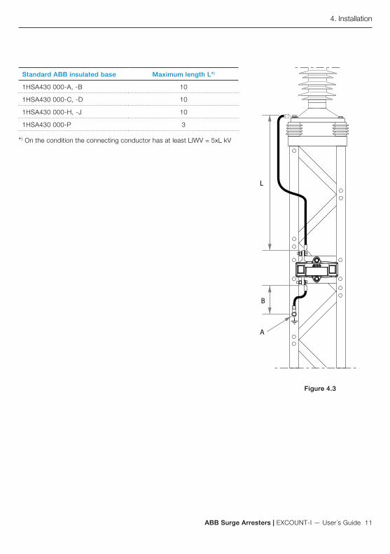
ABB Surge Arresters | EXCOUNT-I — User´s Guide 11
L
A
B
Standard ABB insulated base Maximum length L*)
1HSA430 000-A, -B 10
1HSA430 000-C, -D 10
1HSA430 000-H, -J 10
1HSA430 000-P 3
*) On the condition the connecting conductor has at least LIWV = 5xL kV
4. Installation
Figure 4.3

12 EXCOUNT-I — User´s Guide | ABB Surge Arresters
5. Technical data
GeneralClimatic conditions Sealed water-tight design, IP67
Short-circuit capability 65 kA according to IEC 60099-4
Power supply Built-in solar cells
Battery, alternative for indoor use9-volt Lithium battery with a capacity of minimum 1200mAh.
Surge registrationMinimum counting threshold (8/20 microseconds)
10 A
Surge counting memory capacity 999999 registrations (wrap around)
Time resolution < 0.5 s
Leakage current measurementMeasuring range of total leakage current 0.1 — 50 mApeak
Measuring frequency range 48 — 62 Hz
Laser pointerBattery type LR44-L 1.5 V type Alkaline
Laser pointer wavelength 630 — 680 nm

ABB Surge Arresters | EXCOUNT-I — User´s Guide 13
5. Technical data
EXCOUNT-I versionsEXCOUNT-I can be supplied with an output connection (auxiliary contact) for interfacing to external
signalling equipment. A version with only surge counting function are also available.
Model Surge Counting
Leakage current
measurement
Auxiliary contact Laser pointerincluded
1HSA440000-C Yes
1HSA440000-E Yes Yes
1HSA440000-J Yes Yes Yes
1HSA440000-L Yes Yes Yes Yes

14 EXCOUNT-I — User´s Guide | ABB Surge Arresters
5. Technical data
Position of auxiliary contactThe length of the cable is about 50 cm.
Figure 5.1
1HSA440000-E and 1HSA440000L
76
30

ABB Surge Arresters | EXCOUNT-I — User´s Guide 15
5. Technical data
11 69,5
14
100191
40
95
17
14
158
Dimensions
Figure 5.2

ABB AB High Voltage Products Surge Arresters SE-771 80 Ludvika, Sweden Phone: +46 (0)240 78 20 00 Fax: +46 (0)240 179 83E-Mail: [email protected] www.abb.comwww.abb.com/arrestersonline
©Copyright 2011 ABB
All rights reserved
NOTE! ABB AB is working continuously
to improve the products. We therefore re-
serve the right to change designs, dimen-
sions and data without prior notice.
Contact us
Doc
umen
t 1
HS
A 8
01 0
80-3
0en
EX
CO
UN
T-I U
ser´s
Gui
de,
Ed
ition
2, 2
011-
03