Embed Size (px)
Citation preview
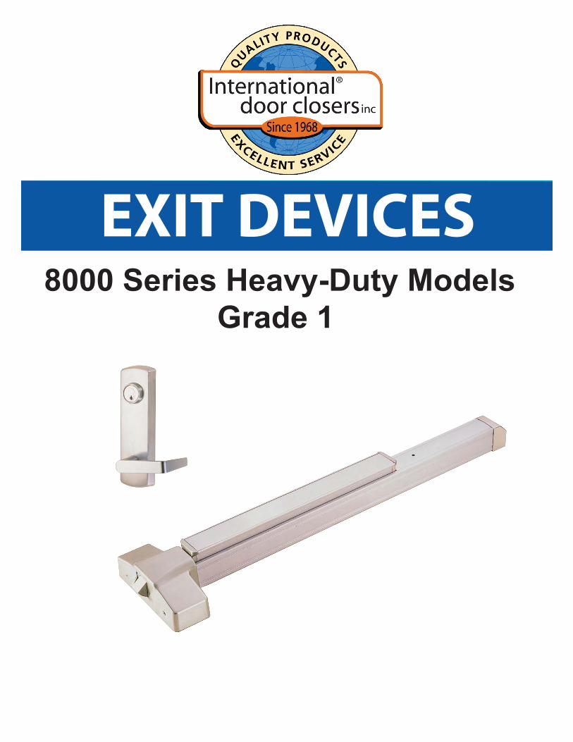
EXIT DEVICES8000 Series Heavy-Duty Models
Grade 1
--Exit Device ------------------------------------------------------------------------------------------- 3
Exit Device ---------------------------------------------------------------------- 3
Rim Exit Devices -------------------------------------------------------------- 6
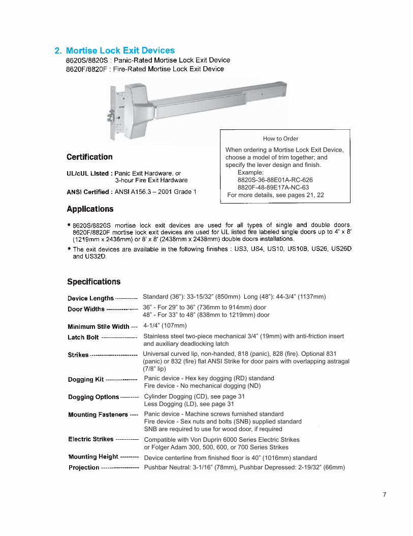
Mortise Lock Exit Devices ------------------------------------------------- 7
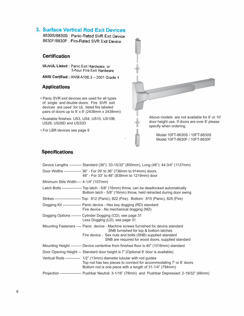
Surface Vertical Rod Exit Devices --------------------------------------- 8
Surface Vertical Rod Exit Devices LBR -------------------------------- 9
Concealed Vertical Rod Exit Devices ----------------------------------- 10
Wood Door Concealed Vertical Rod Exit Devices ------------------ 11
Narrow Design Rim Exit Devices ----------------------------------------- 12
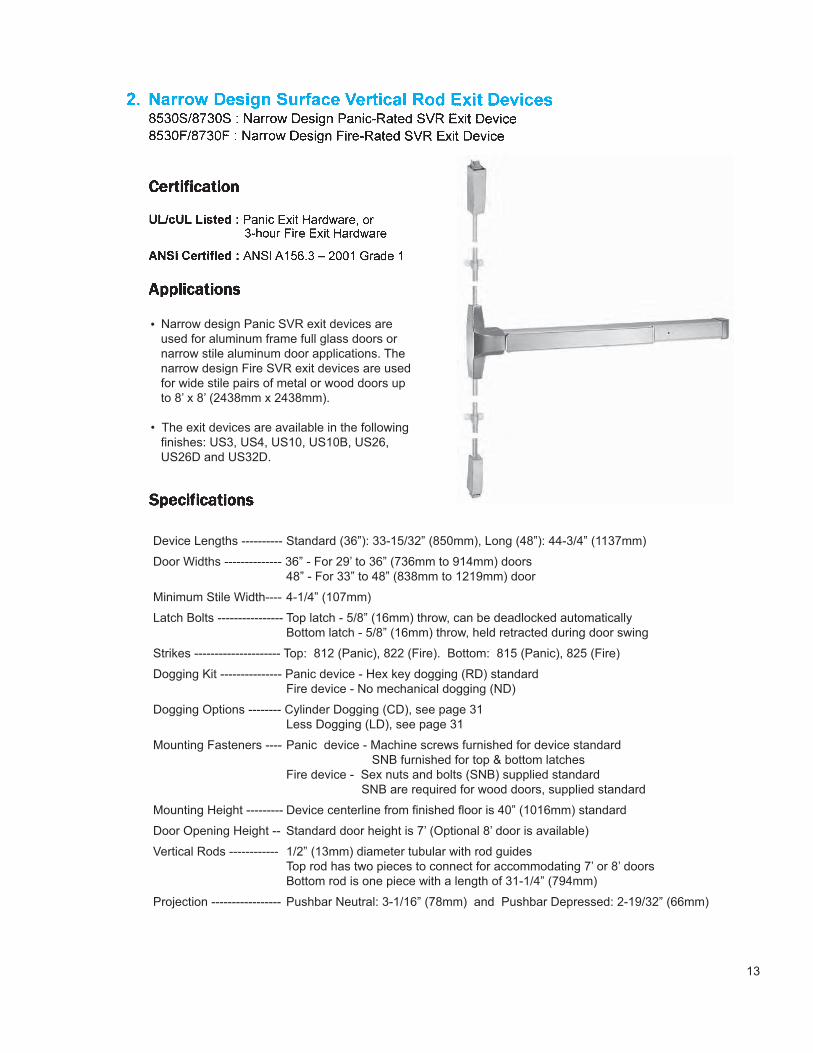
Narrow Design SVR Exit Devices ---------------------------------------- 13
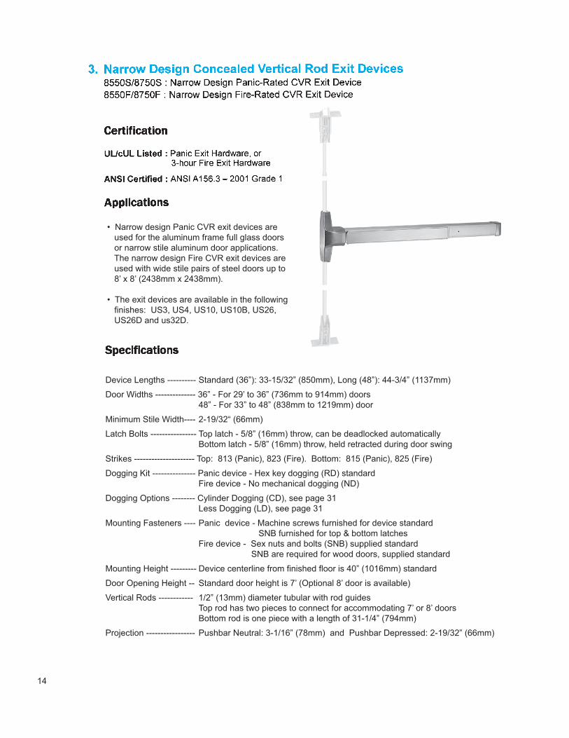
Narrow Design CVR Exit Devices ---------------------------------------- 14
Electrified Exit Devices ------------------------------------------------------ 15
Strikes ------------------------------------------------------------------------------ 16
Dimensions and Parts -------------------------------------------------------- 17
Finishes ---------------------------------------------------------------------------- 19
Double Door Applications --------------------------------------------------- 20
Exterior Trims ------------------------------------------------------------------- 21
Auxiliary Hardware - Moveable Mullions -------------------------------- 27
Door Coordinator ---------------------------------- 29
Fire Latch Bolt -------------------------------------- 31
Cylinders --------------------------------------------- 31
3
IDC 8000 Series exit devices are suitable for using at emergency exits in Commercial, Industrial, Goverment/Industrial, Public Buildings and multi-story residential buildings:
IDC 8000 Series Exit Devices are heavy duty and designed for heavy traffic applications. The devices are Underwriters Laboratory (UL, USA and ULC, Canada) listed for PanicExit Hardware or Fire Exit Hardware, and are certified to ANSI A156.3-2001 Grade 1.
• All devices are non-handed design
• Slight pressure on device touch bar will retract latch(s) for immediate exit
• Auxiliary guarded latch deadlocks latch bolt automatically when door is closed
• High shock-resistant latching mechanical design for protection from vandalism
• All inside components are made of high rust-resistant alloy or heavily electroplated steel
• Anti-fading, electroplated or architectual base material finishes on all exposed surfaces are available
• With a dogging mechanism, users have a choice of hex-key or cylinder operated for positive push-pull action at peak traffic time. This dogging device will also help by increasing the life of the exit device (panic label only).
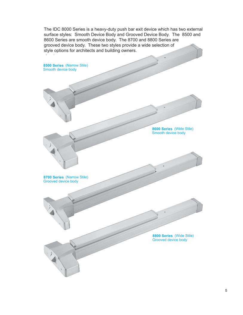
The IDC 8000 Series is a heavy-duty push bar exit device which has two externalsurface styles: Smooth Device Body and Grooved Device Body. The 8500 and8600 Series are smooth device body. The 8700 and 8800 Series aregrooved device body. These two styles provide a wide selection of style options for architects and building owners.
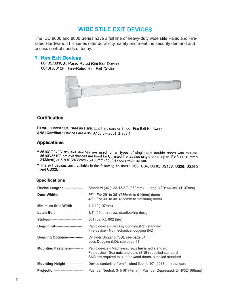
The IDC 8600 and 8800 Series have a full line of heavy-duty wide stile Panic and Fire-rated Hardware. This series offer durability, safety and meet the security demand andaccess control needs of today.
Device Lengths ---------------- Standard (36”): 33-15/32” (850mm) Long (48”): 44-3/4” (1137mm)
Door Widths--------------------- 36” - For 29” to 36” (736mm to 914mm) doors 48” - For 33” to 48” (838mm to 1219mm) doors
Minimum Stile Width--------- 4-1/4” (107mm)
Latch Bolt----------------------- 3/4” (19mm) throw, deadlocking design
Strikes---------------------------- 801 (panic), 802 (fire)
Doggin Kit----------------------- Panic device - Hex key dogging (RD) standard Fire device - No mechanical dogging (ND)
Dogging Options-------------- Cylinder Dogging (CD), see page 31 Less Dogging (LD), see page 31
Mounting Fasteners---------- Panic device - Machine screws furnished standard Fire device - Sex nuts and bolts (SNB) supplied standard SNB are required to use for wood doors, supplied standard
Mounting Height--------------- Device centerline from finished floor is 40” (1016mm) standard
Projection------------------------ Pushbar Neutral: 3-1/16” (78mm), Pushbar Depressed: 2-19/32” (66mm)
Specifications
How to Order
When ordering a Mortise Lock Exit Device,choose a model of trim together; and specify the lever design and finish. Example: 8820S-36-88E01A-RC-626 8820F-48-89E17A-NC-63 For more details, see pages 21, 22
Standard (36”): 33-15/32” (850mm) Long (48”): 44-3/4” (1137mm)
36” - For 29” to 36” (736mm to 914mm) door48” - For 33” to 48” (838mm to 1219mm) door
4-1/4” (107mm)
Stainless steel two-piece mechanical 3/4” (19mm) with anti-friction insertand auxiliary deadlocking latchUniversal curved lip, non-handed, 818 (panic), 828 (fire). Optional 831(panic) or 832 (fire) flat ANSI Strike for door pairs with overlapping astragal(7/8” lip)Panic device - Hex key dogging (RD) standandFire device - No mechanical dogging (ND)
Cylinder Dogging (CD), see page 31Less Dogging (LD), see page 31Panic device - Machine screws furnished standardFire device - Sex nuts and bolts (SNB) supplied standardSNB are required to use for wood door, if required
Compatible with Von Duprin 6000 Series Electric Strikesor Folger Adam 300, 500, 600, or 700 Series Strikes
Device centerline from finished floor is 40” (1016mm) standardPushbar Neutral: 3-1/16” (78mm), Pushbar Depressed: 2-19/32” (66mm)
8
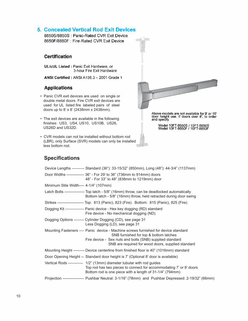
Above models are not available for 9’ or 10’door height use. If doors are over 8’ pleasespecify when ordering.
Model 10FT-8630S / 10FT-8830S Model 10FT-8630F / 10FT-8830F
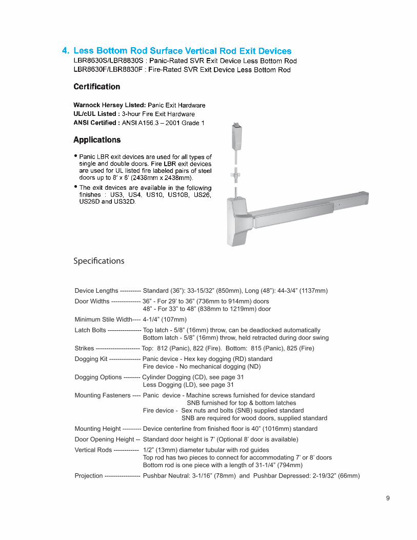
• Panic SVR exit devices are used for all types of single and double doors. Fire SVR exit devices are used for UL listed fire labeled pairs of doors up to 8’ x 8’ (2438mm x 2438mm)
• Available finishes: US3, US4, US10, US10B, US26, US26D and US32D
• For LBR devices see page 9
Device Lengths ---------- Standard (36”): 33-15/32” (850mm), Long (48”): 44-3/4” (1137mm)
Door Widths -------------- 36” - For 29’ to 36” (736mm to 914mm) doors 48” - For 33” to 48” (838mm to 1219mm) door
Minimum Stile Width---- 4-1/4” (107mm)
Latch Bolts ---------------- Top latch - 5/8” (16mm) throw, can be deadlocked automatically Bottom latch - 5/8” (16mm) throw, held retracted during door swing
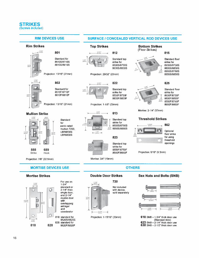
Strikes --------------------- Top: 812 (Panic), 822 (Fire). Bottom: 815 (Panic), 825 (Fire)
Dogging Kit --------------- Panic device - Hex key dogging (RD) standard Fire device - No mechanical dogging (ND)
Dogging Options -------- Cylinder Dogging (CD), see page 31 Less Dogging (LD), see page 31
Mounting Fasteners ---- Panic device - Machine screws furnished for device standard SNB furnished for top & bottom latches Fire device - Sex nuts and bolts (SNB) supplied standard SNB are required for wood doors, supplied standard
Mounting Height --------- Device centerline from finished floor is 40” (1016mm) standard
Door Opening Height -- Standard door height is 7’ (Optional 8’ door is available)
Vertical Rods ------------ 1/2” (13mm) diameter tubular with rod guides Top rod has two pieces to connect for accommodating 7’ or 8’ doors Bottom rod is one piece with a length of 31-1/4” (794mm)
Projection ----------------- Pushbar Neutral: 3-1/16” (78mm) and Pushbar Depressed: 2-19/32” (66mm)
Device Lengths ---------- Standard (36”): 33-15/32” (850mm), Long (48”): 44-3/4” (1137mm)
Door Widths -------------- 36” - For 29’ to 36” (736mm to 914mm) doors 48” - For 33” to 48” (838mm to 1219mm) door
Minimum Stile Width---- 4-1/4” (107mm)
Latch Bolts ---------------- Top latch - 5/8” (16mm) throw, can be deadlocked automatically Bottom latch - 5/8” (16mm) throw, held retracted during door swing
Strikes --------------------- Top: 812 (Panic), 822 (Fire). Bottom: 815 (Panic), 825 (Fire)
Dogging Kit --------------- Panic device - Hex key dogging (RD) standard Fire device - No mechanical dogging (ND)
Dogging Options -------- Cylinder Dogging (CD), see page 31 Less Dogging (LD), see page 31
Mounting Fasteners ---- Panic device - Machine screws furnished for device standard SNB furnished for top & bottom latches Fire device - Sex nuts and bolts (SNB) supplied standard SNB are required for wood doors, supplied standard
Mounting Height --------- Device centerline from finished floor is 40” (1016mm) standard
Door Opening Height -- Standard door height is 7’ (Optional 8’ door is available)
Vertical Rods ------------ 1/2” (13mm) diameter tubular with rod guides Top rod has two pieces to connect for accommodating 7’ or 8’ doors Bottom rod is one piece with a length of 31-1/4” (794mm)
Projection ----------------- Pushbar Neutral: 3-1/16” (78mm) and Pushbar Depressed: 2-19/32” (66mm)
Specifications
10
Device Lengths ---------- Standard (36”): 33-15/32” (850mm), Long (48”): 44-3/4” (1137mm)
Door Widths -------------- 36” - For 29’ to 36” (736mm to 914mm) doors 48” - For 33” to 48” (838mm to 1219mm) door
Minimum Stile Width---- 4-1/4” (107mm)
Latch Bolts ---------------- Top latch - 5/8” (16mm) throw, can be deadlocked automatically Bottom latch - 5/8” (16mm) throw, held retracted during door swing
Strikes --------------------- Top: 813 (Panic), 823 (Fire). Bottom: 815 (Panic), 825 (Fire)
Dogging Kit --------------- Panic device - Hex key dogging (RD) standard Fire device - No mechanical dogging (ND)
Dogging Options -------- Cylinder Dogging (CD), see page 31 Less Dogging (LD), see page 31
Mounting Fasteners ---- Panic device - Machine screws furnished for device standard SNB furnished for top & bottom latches Fire device - Sex nuts and bolts (SNB) supplied standard SNB are required for wood doors, supplied standard
Mounting Height --------- Device centerline from finished floor is 40” (1016mm) standard
Door Opening Height -- Standard door height is 7’ (Optional 8’ door is available)
Vertical Rods ------------ 1/2” (13mm) diameter tubular with rod guides Top rod has two pieces to connect for accommodating 7’ or 8’ doors Bottom rod is one piece with a length of 31-1/4” (794mm)
Projection ----------------- Pushbar Neutral: 3-1/16” (78mm) and Pushbar Depressed: 2-19/32” (66mm)
• Panic CVR exit devices are used on single or double metal doors. Fire CVR exit devices are used for UL listed fire labeled pairs of steel doors up to 8’ x 8’ (2438mm x 2438mm).
• The exit devices are available in the following finishes: US3, US4, US10, US10B, US26, US26D and US32D.
• CVR models can not be installed without bottom rod (LBR), only Surface (SVR) models can only be installed less bottom rod.
Specifications
11
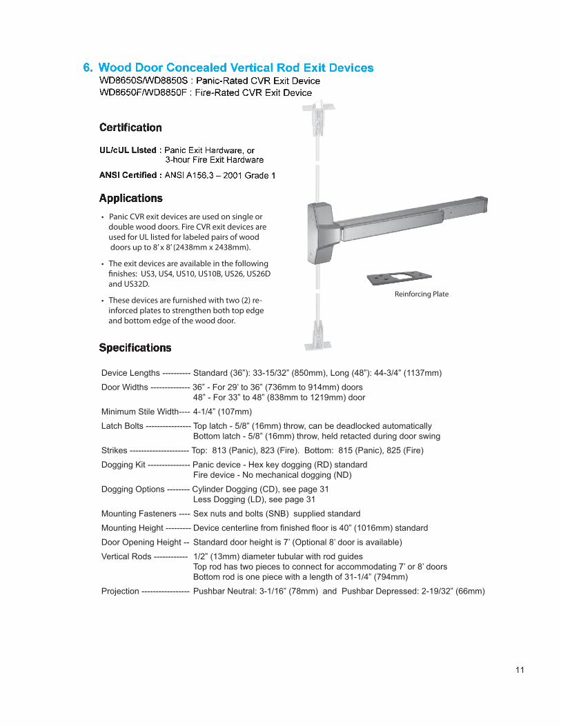
Reinforced PlateReinforcing Plate
Device Lengths ---------- Standard (36”): 33-15/32” (850mm), Long (48”): 44-3/4” (1137mm)
Door Widths -------------- 36” - For 29’ to 36” (736mm to 914mm) doors 48” - For 33” to 48” (838mm to 1219mm) door
Minimum Stile Width---- 4-1/4” (107mm)
Latch Bolts ---------------- Top latch - 5/8” (16mm) throw, can be deadlocked automatically Bottom latch - 5/8” (16mm) throw, held retacted during door swing
Strikes --------------------- Top: 813 (Panic), 823 (Fire). Bottom: 815 (Panic), 825 (Fire)
Dogging Kit --------------- Panic device - Hex key dogging (RD) standard Fire device - No mechanical dogging (ND)
Dogging Options -------- Cylinder Dogging (CD), see page 31 Less Dogging (LD), see page 31
Mounting Fasteners ---- Sex nuts and bolts (SNB) supplied standard
Mounting Height --------- Device centerline from finished floor is 40” (1016mm) standard
Door Opening Height -- Standard door height is 7’ (Optional 8’ door is available)
Vertical Rods ------------ 1/2” (13mm) diameter tubular with rod guides Top rod has two pieces to connect for accommodating 7’ or 8’ doors Bottom rod is one piece with a length of 31-1/4” (794mm)
Projection ----------------- Pushbar Neutral: 3-1/16” (78mm) and Pushbar Depressed: 2-19/32” (66mm)
12
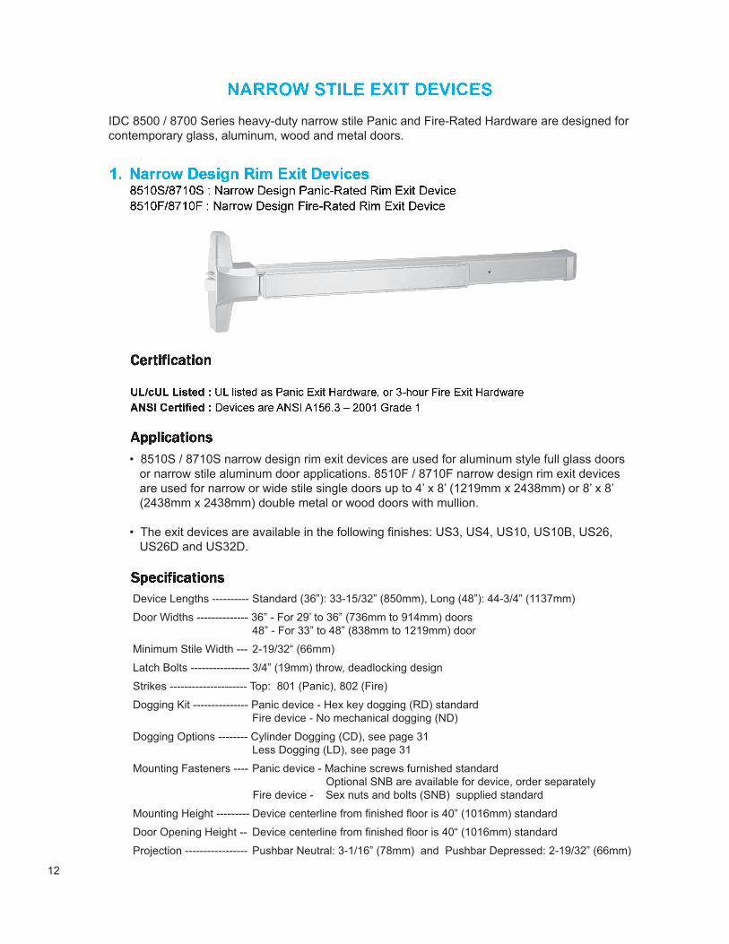
IDC 8500 / 8700 Series heavy-duty narrow stile Panic and Fire-Rated Hardware are designed forcontemporary glass, aluminum, wood and metal doors.
• 8510S / 8710S narrow design rim exit devices are used for aluminum style full glass doors or narrow stile aluminum door applications. 8510F / 8710F narrow design rim exit devices are used for narrow or wide stile single doors up to 4’ x 8’ (1219mm x 2438mm) or 8’ x 8’ (2438mm x 2438mm) double metal or wood doors with mullion.
• The exit devices are available in the following finishes: US3, US4, US10, US10B, US26, US26D and US32D.
Device Lengths ---------- Standard (36”): 33-15/32” (850mm), Long (48”): 44-3/4” (1137mm)
Door Widths -------------- 36” - For 29’ to 36” (736mm to 914mm) doors 48” - For 33” to 48” (838mm to 1219mm) door
Minimum Stile Width --- 2-19/32“ (66mm)
Latch Bolts ---------------- 3/4” (19mm) throw, deadlocking design
Strikes --------------------- Top: 801 (Panic), 802 (Fire)
Dogging Kit --------------- Panic device - Hex key dogging (RD) standard Fire device - No mechanical dogging (ND)
Dogging Options -------- Cylinder Dogging (CD), see page 31 Less Dogging (LD), see page 31
Mounting Fasteners ---- Panic device - Machine screws furnished standard Optional SNB are available for device, order separately Fire device - Sex nuts and bolts (SNB) supplied standard
Mounting Height --------- Device centerline from finished floor is 40” (1016mm) standard
Door Opening Height -- Device centerline from finished floor is 40“ (1016mm) standard
Projection ----------------- Pushbar Neutral: 3-1/16” (78mm) and Pushbar Depressed: 2-19/32” (66mm)
13
Device Lengths ---------- Standard (36”): 33-15/32” (850mm), Long (48”): 44-3/4” (1137mm)
Door Widths -------------- 36” - For 29’ to 36” (736mm to 914mm) doors 48” - For 33” to 48” (838mm to 1219mm) door
Minimum Stile Width---- 4-1/4” (107mm)
Latch Bolts ---------------- Top latch - 5/8” (16mm) throw, can be deadlocked automatically Bottom latch - 5/8” (16mm) throw, held retracted during door swing
Strikes --------------------- Top: 812 (Panic), 822 (Fire). Bottom: 815 (Panic), 825 (Fire)
Dogging Kit --------------- Panic device - Hex key dogging (RD) standard Fire device - No mechanical dogging (ND)
Dogging Options -------- Cylinder Dogging (CD), see page 31 Less Dogging (LD), see page 31
Mounting Fasteners ---- Panic device - Machine screws furnished for device standard SNB furnished for top & bottom latches Fire device - Sex nuts and bolts (SNB) supplied standard SNB are required for wood doors, supplied standard
Mounting Height --------- Device centerline from finished floor is 40” (1016mm) standard
Door Opening Height -- Standard door height is 7’ (Optional 8’ door is available)
Vertical Rods ------------ 1/2” (13mm) diameter tubular with rod guides Top rod has two pieces to connect for accommodating 7’ or 8’ doors Bottom rod is one piece with a length of 31-1/4” (794mm)
Projection ----------------- Pushbar Neutral: 3-1/16” (78mm) and Pushbar Depressed: 2-19/32” (66mm)
Narrow design Panic SVR exit devices are used for aluminum frame full glass doors or narrow stile aluminum door applications. The narrow design Fire SVR exit devices are used for wide stile pairs of metal or wood doors up to 8’ x 8’ (2438mm x 2438mm).
• The exit devices are available in the following finishes: US3, US4, US10, US10B, US26, US26D and US32D.
14
Device Lengths ---------- Standard (36”): 33-15/32” (850mm), Long (48”): 44-3/4” (1137mm)
Door Widths -------------- 36” - For 29’ to 36” (736mm to 914mm) doors 48” - For 33” to 48” (838mm to 1219mm) door
Minimum Stile Width---- 2-19/32“ (66mm)
Latch Bolts ---------------- Top latch - 5/8” (16mm) throw, can be deadlocked automatically Bottom latch - 5/8” (16mm) throw, held retracted during door swing
Strikes --------------------- Top: 813 (Panic), 823 (Fire). Bottom: 815 (Panic), 825 (Fire)
Dogging Kit --------------- Panic device - Hex key dogging (RD) standard Fire device - No mechanical dogging (ND)
Dogging Options -------- Cylinder Dogging (CD), see page 31 Less Dogging (LD), see page 31
Mounting Fasteners ---- Panic device - Machine screws furnished for device standard SNB furnished for top & bottom latches Fire device - Sex nuts and bolts (SNB) supplied standard SNB are required for wood doors, supplied standard
Mounting Height --------- Device centerline from finished floor is 40” (1016mm) standard
Door Opening Height -- Standard door height is 7’ (Optional 8’ door is available)
Vertical Rods ------------ 1/2” (13mm) diameter tubular with rod guides Top rod has two pieces to connect for accommodating 7’ or 8’ doors Bottom rod is one piece with a length of 31-1/4” (794mm)
Projection ----------------- Pushbar Neutral: 3-1/16” (78mm) and Pushbar Depressed: 2-19/32” (66mm)
• Narrow design Panic CVR exit devices are used for the aluminum frame full glass doors or narrow stile aluminum door applications. The narrow design Fire CVR exit devices are used with wide stile pairs of steel doors up to 8’ x 8’ (2438mm x 2438mm).
• The exit devices are available in the following finishes: US3, US4, US10, US10B, US26, US26D and us32D.
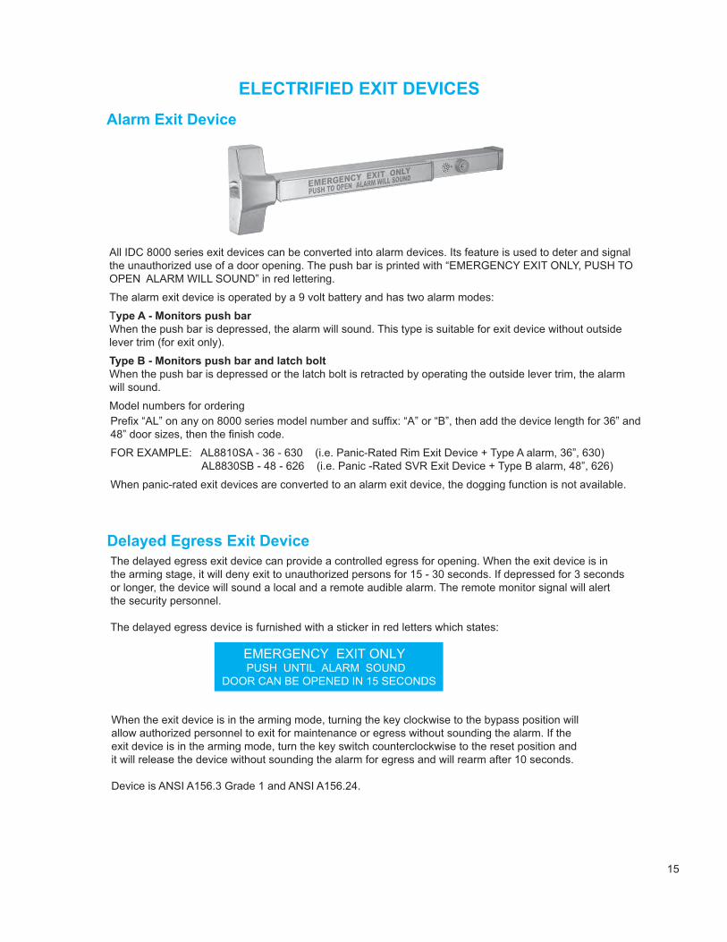
All IDC 8000 series exit devices can be converted into alarm devices. Its feature is used to deter and signalthe unauthorized use of a door opening. The push bar is printed with “EMERGENCY EXIT ONLY, PUSH TOOPEN ALARM WILL SOUND” in red lettering.
The alarm exit device is operated by a 9 volt battery and has two alarm modes:
Type A - Monitors push barWhen the push bar is depressed, the alarm will sound. This type is suitable for exit device without outsidelever trim (for exit only).
Type B - Monitors push bar and latch boltWhen the push bar is depressed or the latch bolt is retracted by operating the outside lever trim, the alarmwill sound.
Model numbers for orderingPrefix “AL” on any on 8000 series model number and suffix: “A” or “B”, then add the device length for 36” and48” door sizes, then the finish code.
FOR EXAMPLE: AL8810SA - 36 - 630 (i.e. Panic-Rated Rim Exit Device + Type A alarm, 36”, 630) AL8830SB - 48 - 626 (i.e. Panic -Rated SVR Exit Device + Type B alarm, 48”, 626)
When panic-rated exit devices are converted to an alarm exit device, the dogging function is not available.
The delayed egress exit device can provide a controlled egress for opening. When the exit device is in the arming stage, it will deny exit to unauthorized persons for 15 - 30 seconds. If depressed for 3 secondsor longer, the device will sound a local and a remote audible alarm. The remote monitor signal will alertthe security personnel.
The delayed egress device is furnished with a sticker in red letters which states:
When the exit device is in the arming mode, turning the key clockwise to the bypass position will allow authorized personnel to exit for maintenance or egress without sounding the alarm. If the exit device is in the arming mode, turn the key switch counterclockwise to the reset position and it will release the device without sounding the alarm for egress and will rearm after 10 seconds.
Device is ANSI A156.3 Grade 1 and ANSI A156.24.
17
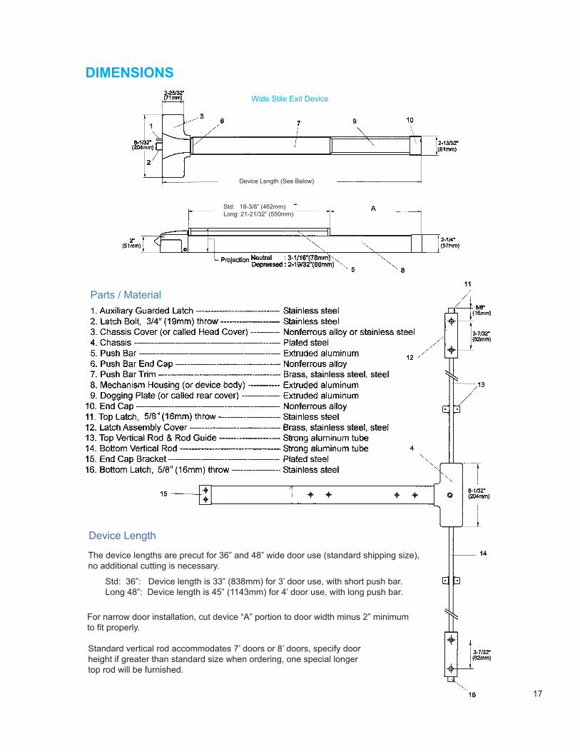
See BelowDevice Length (See Below)
Std: 18-3/8” (462mm)Long: 21-21/32” (550mm)
Parts / Material
Device Length
Std: 36”: Device length is 33” (838mm) for 3’ door use, with short push bar.Long 48”: Device length is 45” (1143mm) for 4’ door use, with long push bar.
Standard vertical rod accommodates 7’ doors or 8’ doors, specify doorheight if greater than standard size when ordering, one special longertop rod will be furnished.
For narrow door installation, cut device “A” portion to door width minus 2” minimumto fit properly.
The device lengths are precut for 36” and 48” wide door use (standard shipping size), no additional cutting is necessary.
18
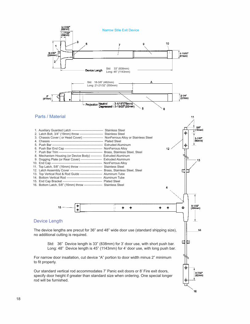
Std: 33” (838mm)Long: 45” (1143mm)
Std: 18-3/8” (462mm)Long: 21-21/32” (550mm)
Parts / Material
1. Auxiliary Guarded Latch ------------------------------- Stainless Steel 2. Latch Bolt, 3/4” (19mm) throw ----------------------- Stainless Steel 3. Chassis Cover ( or Head Cover) -------------------- NonFerrous Alloy or Stainless Steel 4. Chassis ---------------------------------------------------- Plated Steel 5. Push Bar -------------------------------------------------- Extruded Aluminum 6. Push Bar End Cap ------------------------------------- NonFerrous Alloy 7. Push Bar Trim ------------------------------------------- Brass, Stainless Steel, Steel 8. Mechanism Housing (or Device Body) ----------- Extruded Aluminum 9. Dogging Plate (or Rear Cover) --------------------- Extruded Aluminum10. End Cap -------------------------------------------------- NonFerrous Alloy11. Top Latch, 5/8” (16mm) throw ----------------------- Stainless Steel12. Latch Assembly Cover -------------------------------- Brass, Stainless Steel, Steel13. Top Vertical Rod & Rod Guide ---------------------- Aluminum Tube14. Bottom Vertical Rod ----------------------------------- Aluminum Tube15. End Cap Bracket --------------------------------------- Plated Steel16. Bottom Latch, 5/8” (16mm) throw ------------------ Stainless Steel
Device Length
The device lengths are precut for 36” and 48” wide door use (standard shipping size),no additional cutting is required.
Std: 36” Device length is 33” (838mm) for 3’ door use, with short push bar. Long: 48” Device length is 45” (1143mm) for 4’ door use, with long push bar.
For narrow door insallation, cut device “A” portion to door width minus 2” minimumto fit properly.
Our standard vertical rod accommodates 7’ Panic exit doors or 8’ Fire exit doors, specify door height if greater than standard size when ordering. One special longerrod will be furnished.
19
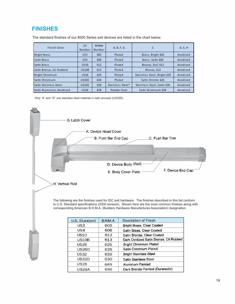
The standard finishes of our 8000 Series exit devices are listed in the chart below.
Finish ColorUS
NumberBHMA
NumberA, B, F, G C D, E, H
Bright Brass US3 605 Plated Brass , Bright 605 Anodized
Sa�n Brass US4 606 Plated Brass , Sa�n 606 Anodized
Sa�n Brass US10 612 Plated Bronze, Dul l 612 Anodized
Sa�n Bronze, Oi l Rubbed US10B 613 Plated Bronze, 613 Anodized
Bright Chromium US26 625 Plated Sta inless Steel , Bright 629 Anodized
Sa�n Chromium US26D 626 Plated Sa�n Chrome 626 Anodized
Sa�n Sta inless Steel US32D 630 Sta inless Steel* Sta inless Steel , Sa�n 630 Anodized
Sa�n Aluminum, Anodized US28 628 Powder Coat Sa�n Aluminum 628 Anodized
Only “A” and “G” use stainless steel material in satin process (US32D)
The following are the finishes used for IDC exit hardware. The finishes described in this list conformto U.S. Standard specifications (2000 revision). Shown here are the most common finishes along withcorresponding American B.H.M.A. (Builders Hardware Manufactures Association) designation.
20
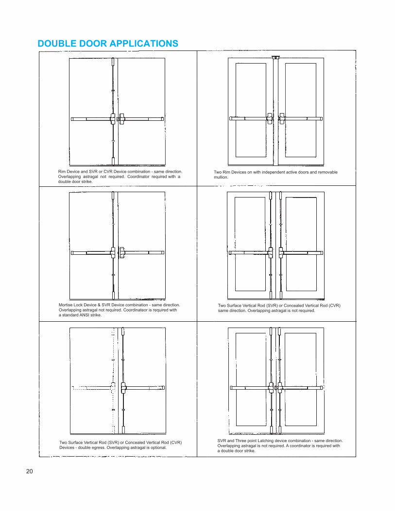
Rim Device and SVR or CVR Device combination - same direction.Overlapping astragal not required. Coordinator required with adouble door strike.
Two Rim Devices on with independent active doors and removablemullion.
Mortise Lock Device & SVR Device combination - same direction.Overlapping astragal not required. Coordinateor is required witha standard ANSI strike.
Two Surface Vertical Rod (SVR) or Concealed Vertical Rod (CVR)same direction. Overlapping astragal is not required.
Two Surface Vertical Rod (SVR) or Concealed Vertical Rod (CVR)Devices - double egress. Overlapping astragal is optional.
SVR and Three point Latching device combination - same direction.Overlapping astragal is not required. A coordinator is required witha double door strike.
21
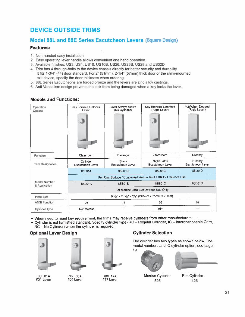
(Square Design)
1. Non-handed easy installation2. Easy operating lever handle allows convenient one hand operation.3. Available finishes: US3, US4, US10, US10B, US26, US26B, US28 and US32D4. Trim has 4 through-bolts to the device chassis directly for better security and durability. It fits 1-3/4” (44) door standard. For 2” (51mm), 2-1/4” (57mm) thick door or the shim-mounted exit device, specify the door thickness when ordering.5. 88L Series Escutcheons are forged bronze and the levers are zinc alloy castings.6. Anti-Vandalism design prevents the lock from being damaged when a key locks the lever.
OperationOptions
Function
Trim Designation
Model Number& Application
Plate Size
ANSI Function
Cylinder Type
22
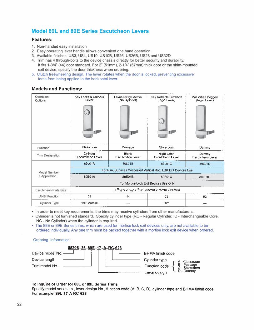
1. Non-handed easy installation2. Easy operating lever handle allows convenient one hand operation.3. Available finishes: US3, US4, US10, US10B, US26, US26B, US28 and US32D4. Trim has 4 through-bolts to the device chassis directly for better security and durability. It fits 1-3/4” (44) door standard. For 2” (51mm), 2-1/4” (57mm) thick door or the shim-mounted exit device, specify the door thickness when ordering.5. Clutch freewheeling design. The lever rotates when the door is locked, preventing excessive force from being applied to the horizontal lever.
Opertaion Options
Function
Trim Designation
Model Number& Application
Escutcheon Plate Size
ANSI Function
Cylinder Type
• In order to meet key requirements, the trims may receive cylinders from other manufacturers.• Cylinder is not furnished standard. Specify cylinder type (RC - Regular Cylinder, IC - Interchangeable Core, NC - No Cylinder) when the cylinder is required.• The 88E or 89E Series trims, which are used for mortise lock exit devices only, are not available to be ordered individually. Any one trim must be packed together with a mortise lock exit device when ordered.
Ordering Information:
23
To inquire or order for 87E Series Trims with mortise lock device, specify the following form:
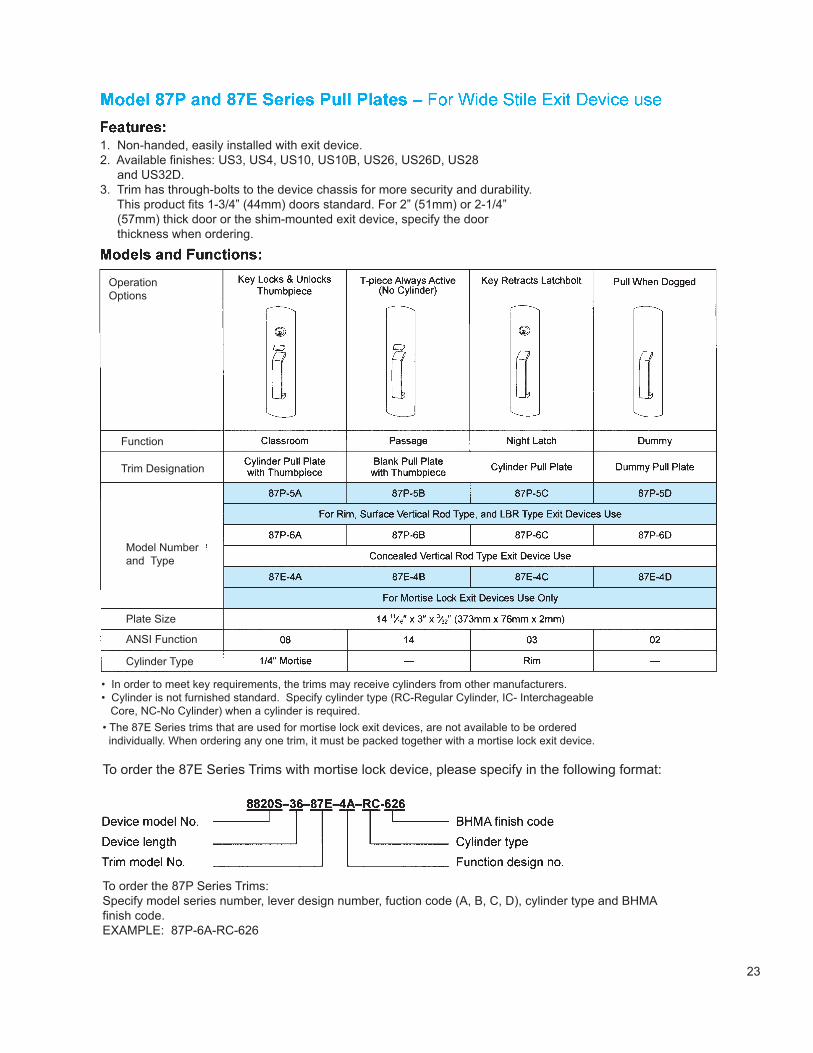
1. Non-handed, easily installed with exit device.2. Available finishes: US3, US4, US10, US10B, US26, US26D, US28 and US32D.3. Trim has through-bolts to the device chassis for more security and durability. This product fits 1-3/4” (44mm) doors standard. For 2” (51mm) or 2-1/4” (57mm) thick door or the shim-mounted exit device, specify the door thickness when ordering.
OperationOptions
Function
Trim Designation
Model Numberand Type
Plate Size
ANSI Function
Cylinder Type
• In order to meet key requirements, the trims may receive cylinders from other manufacturers.• Cylinder is not furnished standard. Specify cylinder type (RC-Regular Cylinder, IC- Interchageable Core, NC-No Cylinder) when a cylinder is required.• The 87E Series trims that are used for mortise lock exit devices, are not available to be ordered individually. When ordering any one trim, it must be packed together with a mortise lock exit device.
To order the 87E Series Trims with mortise lock device, please specify in the following format:
To order the 87P Series Trims:Specify model series number, lever design number, fuction code (A, B, C, D), cylinder type and BHMAfinish code.EXAMPLE: 87P-6A-RC-626
24
To inquire or order for 86E Series Trims with mortise lock device, specify the following form:
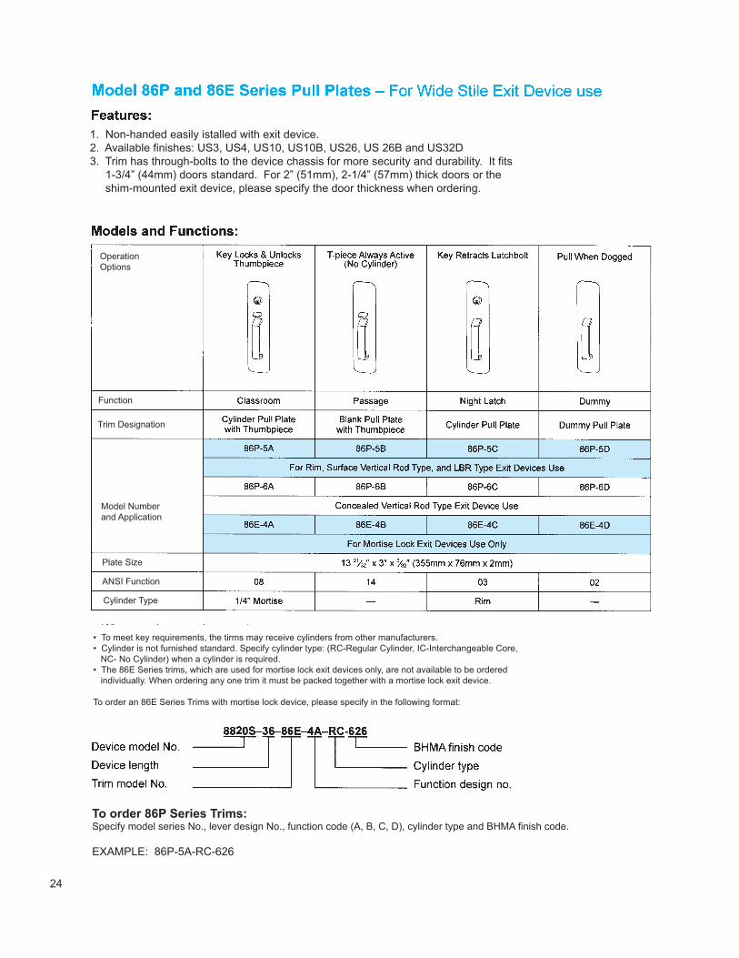
1. Non-handed easily istalled with exit device.2. Available finishes: US3, US4, US10, US10B, US26, US 26B and US32D3. Trim has through-bolts to the device chassis for more security and durability. It fits 1-3/4” (44mm) doors standard. For 2” (51mm), 2-1/4” (57mm) thick doors or the shim-mounted exit device, please specify the door thickness when ordering.
OperationOptions
Function
Trim Designation
Model Numberand Application
Plate Size
ANSI Function
Cylinder Type
• To meet key requirements, the tirms may receive cylinders from other manufacturers.• Cylinder is not furnished standard. Specify cylinder type: (RC-Regular Cylinder, IC-Interchangeable Core, NC- No Cylinder) when a cylinder is required.• The 86E Series trims, which are used for mortise lock exit devices only, are not available to be ordered individually. When ordering any one trim it must be packed together with a mortise lock exit device.
To order an 86E Series Trims with mortise lock device, please specify in the following format:
To order 86P Series Trims:Specify model series No., lever design No., function code (A, B, C, D), cylinder type and BHMA finish code.
EXAMPLE: 86P-5A-RC-626
25
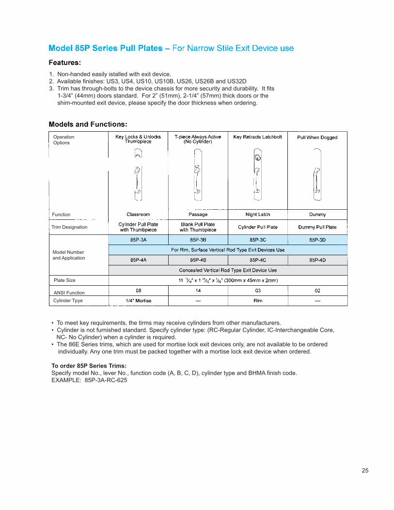
1. Non-handed easily istalled with exit device.2. Available finishes: US3, US4, US10, US10B, US26, US26B and US32D3. Trim has through-bolts to the device chassis for more security and durability. It fits 1-3/4” (44mm) doors standard. For 2” (51mm), 2-1/4” (57mm) thick doors or the shim-mounted exit device, please specify the door thickness when ordering.
• To meet key requirements, the tirms may receive cylinders from other manufacturers.• Cylinder is not furnished standard. Specify cylinder type: (RC-Regular Cylinder, IC-Interchangeable Core, NC- No Cylinder) when a cylinder is required.• The 86E Series trims, which are used for mortise lock exit devices only, are not available to be ordered individually. Any one trim must be packed together with a mortise lock exit device when ordered.
To order 85P Series Trims:Specify model No., lever No., function code (A, B, C, D), cylinder type and BHMA finish code.EXAMPLE: 85P-3A-RC-625
OperationOptions
Function
Trim Designation
Model Numberand Application
Plate Size
ANSI FunctionCylinder Tpye
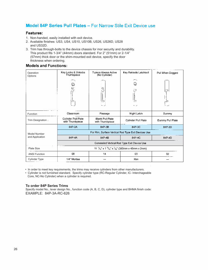
1. Non-handed, easily installed with exit device.2. Available finishes: US3, US4, US10, US10B, US26, US26D, US28 and US32D.3. Trim has through-bolts to the device chassis for mor security and durability. This product fits 1-3/4” (44mm) doors standard. For 2” (51mm) or 2-1/4” (57mm) thick door or the shim-mounted exit device, specify the door thickness when ordering.
• In order to meet key requirements, the trims may receive cylinders from other manufacturers.• Cylinder is not furnished standard. Specify cylinder type (RC-Regular Cylinder, IC- Interchageable Core, NC-No Cylinder) when a cylinder is required.
To order 84P Series TrimsSpecify model No., lever design No., function code (A, B, C, D), cylinder type and BHMA finish code:EXAMPLE: 84P-3A-RC-626
Operation Options
Function
Trim Designation
Model Numberand Application
Plate Size
ANSI Function
Cylinder Type
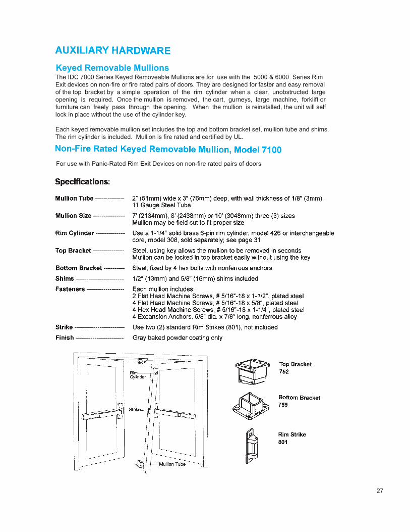
The IDC 7000 Series Keyed Removeable Mullions are for use with the 5000 & 6000 Series RimExit devices on non-fire or fire rated pairs of doors. They are designed for faster and easy removalof the top bracket by a simple operation of the rim cylinder when a clear, unobstructed largeopening is required. Once the mullion is removed, the cart, gurneys, large machine, forklift orfurniture can freely pass through the opening. When the mullion is reinstalled, the unit will selflock in place without the use of the cylinder key.
Each keyed removable mullion set includes the top and bottom bracket set, mullion tube and shims.The rim cylinder is included. Mullion is fire rated and certified by UL.
For use with Panic-Rated Rim Exit Devices on non-fire rated pairs of doors
28
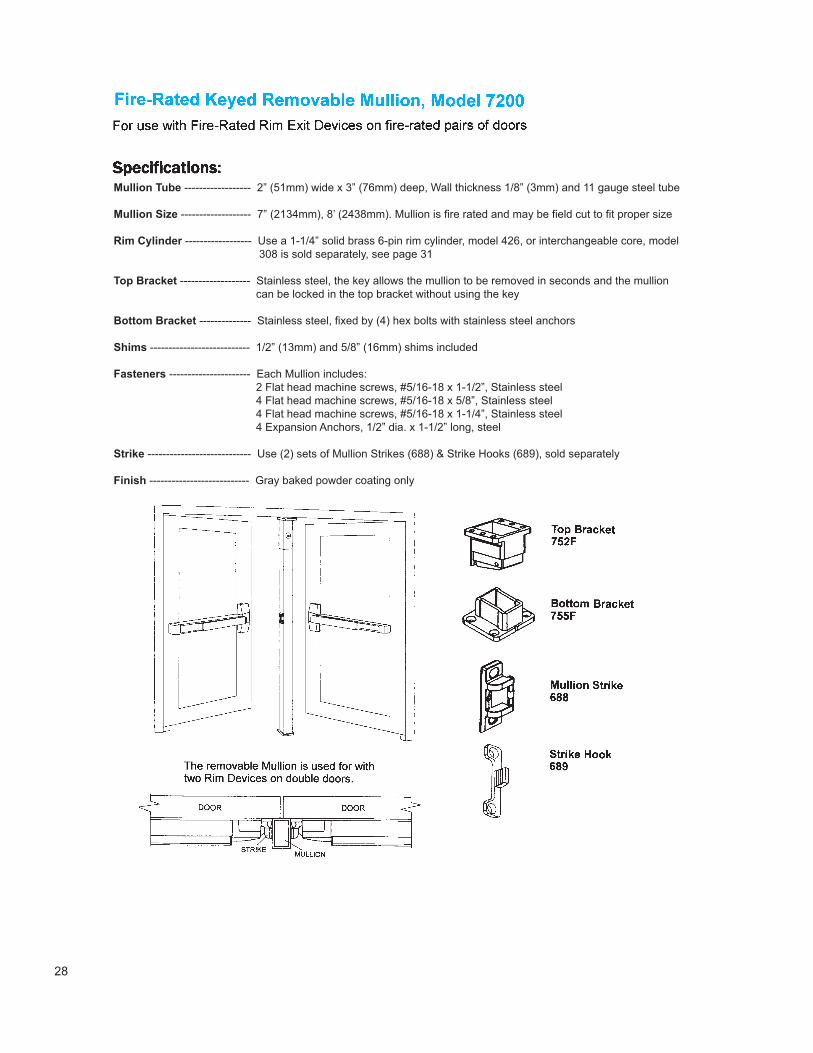
Mullion Tube ------------------ 2” (51mm) wide x 3” (76mm) deep, Wall thickness 1/8” (3mm) and 11 gauge steel tube
Mullion Size ------------------- 7” (2134mm), 8’ (2438mm). Mullion is fire rated and may be field cut to fit proper size
Rim Cylinder ------------------ Use a 1-1/4” solid brass 6-pin rim cylinder, model 426, or interchangeable core, model 308 is sold separately, see page 31
Top Bracket ------------------- Stainless steel, the key allows the mullion to be removed in seconds and the mullion can be locked in the top bracket without using the key
Bottom Bracket -------------- Stainless steel, fixed by (4) hex bolts with stainless steel anchors
Shims --------------------------- 1/2” (13mm) and 5/8” (16mm) shims included
Fasteners ---------------------- Each Mullion includes: 2 Flat head machine screws, #5/16-18 x 1-1/2”, Stainless steel 4 Flat head machine screws, #5/16-18 x 5/8”, Stainless steel 4 Flat head machine screws, #5/16-18 x 1-1/4”, Stainless steel 4 Expansion Anchors, 1/2” dia. x 1-1/2” long, steel
Strike ---------------------------- Use (2) sets of Mullion Strikes (688) & Strike Hooks (689), sold separately
Finish --------------------------- Gray baked powder coating only
29
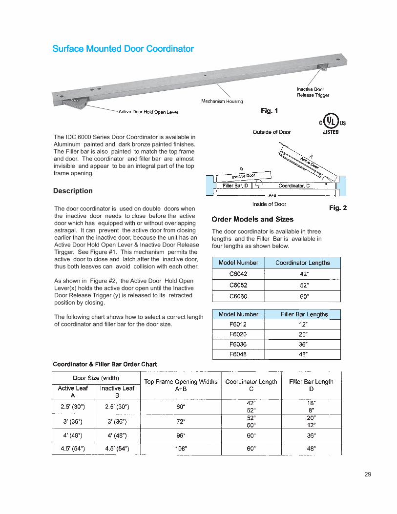
The IDC 6000 Series Door Coordinator is available inAluminum painted and dark bronze painted finishes.The Filler bar is also painted to match the top frameand door. The coordinator and filler bar are almost invisible and appear to be an integral part of the topframe opening.
Description
The door coordinator is used on double doors whenthe inactive door needs to close before the activedoor which has equipped with or without overlappingastragal. It can prevent the active door from closingearlier than the inactive door, because the unit has anActive Door Hold Open Lever & Inactive Door ReleaseTirgger. See Figure #1. This mechanism permits theactive door to close and latch after the inactive door,thus both leasves can avoid collision with each other.
As shown in Figure #2, the Active Door Hold Open Lever(x) holds the active door open until the InactiveDoor Release Trigger (y) is released to its retracted position by closing.
The following chart shows how to select a correct length of coordinator and filler bar for the door size.
The door coordinator is available in threelengths and the Filler Bar is available in four lengths as shown below.
30
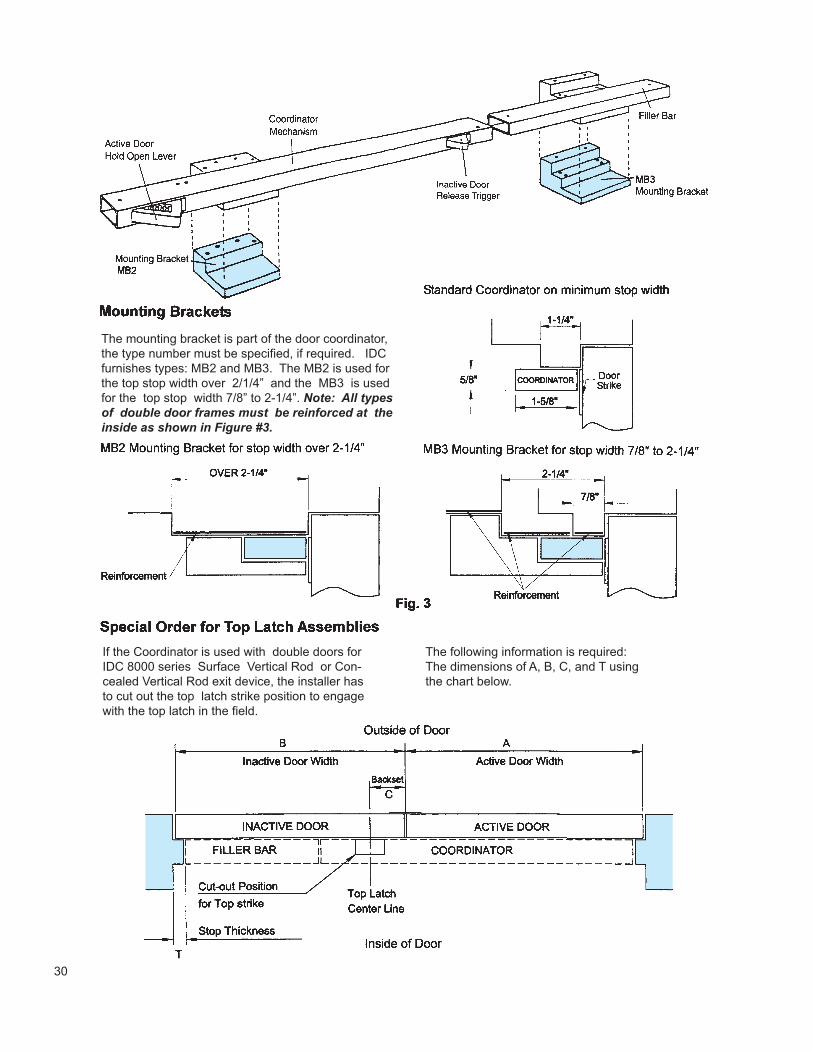
The mounting bracket is part of the door coordinator,the type number must be specified, if required. IDCfurnishes types: MB2 and MB3. The MB2 is used forthe top stop width over 2/1/4” and the MB3 is used for the top stop width 7/8” to 2-1/4”. Note: All typesof double door frames must be reinforced at the inside as shown in Figure #3.
If the Coordinator is used with double doors forIDC 8000 series Surface Vertical Rod or Con-cealed Vertical Rod exit device, the installer hasto cut out the top latch strike position to engagewith the top latch in the field.
The following information is required: The dimensions of A, B, C, and T usingthe chart below.
31
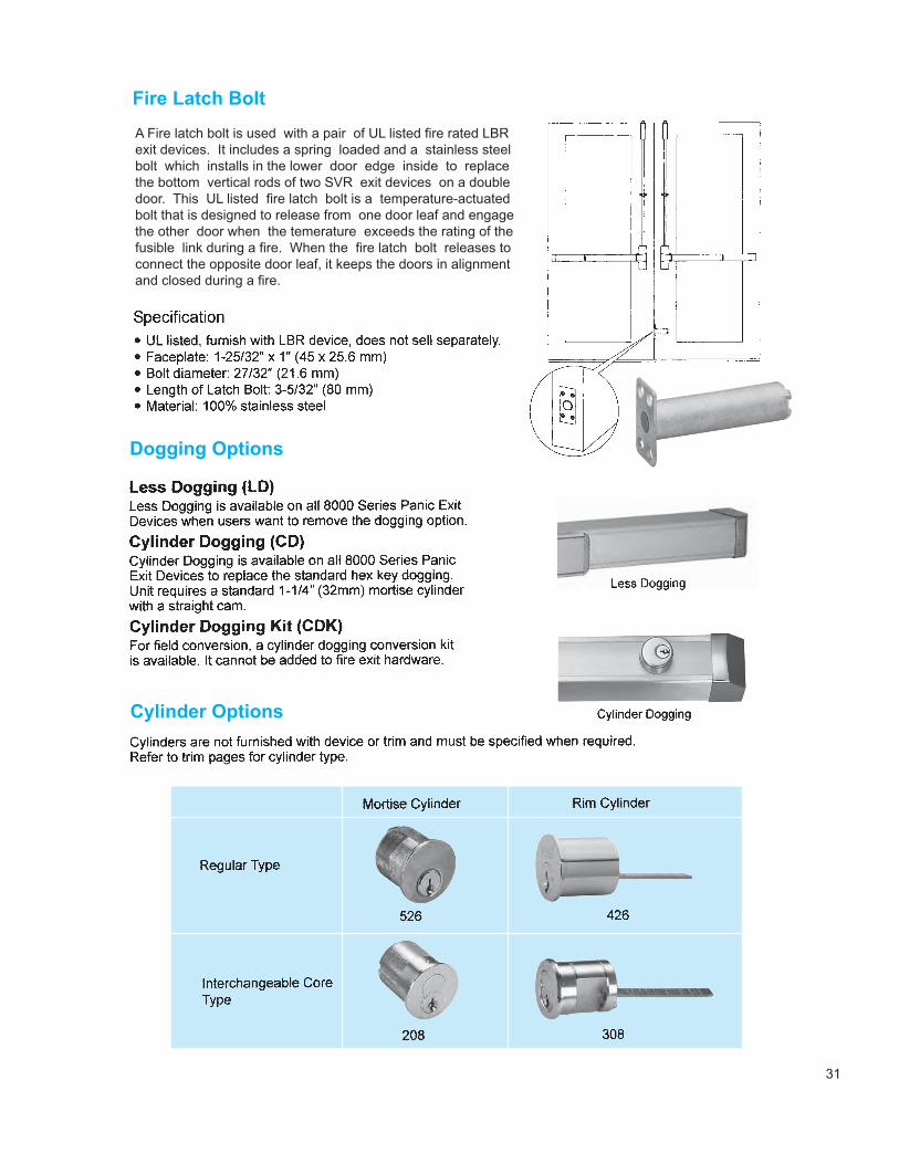
A Fire latch bolt is used with a pair of UL listed fire rated LBRexit devices. It includes a spring loaded and a stainless steelbolt which installs in the lower door edge inside to replacethe bottom vertical rods of two SVR exit devices on a doubledoor. This UL listed fire latch bolt is a temperature-actuatedbolt that is designed to release from one door leaf and engagethe other door when the temerature exceeds the rating of the fusible link during a fire. When the fire latch bolt releases toconnect the opposite door leaf, it keeps the doors in alignmentand closed during a fire.

VISIT our website: intldoorclosers.com
EAST: 1-800-225-6737 • FAX: 1- 615-885-0903
WEST: 1-800-544-4422 • FAX: 1-714-666-2215
EAST:INTERNATIONAL DOOR CLOSERS, INC.
1920 AIR LANE DRIVENASHVILLE, TN 37210
1140 N. KRAEMER PLACEINTERNATIONAL DOOR CLOSERS, INC.
WEST:
ANAHEIM, CA 92806
PROUD OF OUR PASTFOCUSED ON THE FUTURE
COPYRIGHT 2008 INTERNATIONAL DOOR CLOSERS, INC