Embed Size (px)
Citation preview
Advanced Linear and Rotary Actuators with Embedded Electronics
Tritex II™ AC or DCPowered Actuators
Courtesy of Steven Engineering, Inc. - 230 Ryan Way, South San Francisco, CA 94080-5370 - Main Office: (650) 588-9200 - Outside Local Area: (800) 258-9200 - www.stevenengineering.com

Industry’s Most Compact All-In-One Linear & Rotary Motion Actuators
PLC
TritexActuator
TritexActuator
TritexActuator
TritexActuator
PowerSupply
PLC
Serv
oD
rive
Serv
oD
rive
Serv
oD
rive
Serv
oD
rive
PowerSupply
Servo Motor Actuator
Servo Motor
Servo Motor
Servo Motor
Small and Shallow Panel With No Servo Drives
Economical Power & I/O Cables
Large Panel with Space and Depth for Servo Drives
Costly Servo Power and Feedback Cables
Tritex II System
Alternative Systems
By combining the latest electronic power technology with advanced thermal management modeling technology, Exlar has set a new benchmark for electric actuator performance versus size. The Tritex II actuators now integrate an AC or DC powered servo drive, digital position controller, brushless motor and linear or rotary actuator in one elegant, compact, sealed package. Now you can distribute motion control and solve your application with one integrated device. Simply connect power, I/O, communications and go!
Dramatically Reduce Space Requirements
Tritex II actuators are the highest power density, smallest footprint servo drive devices on the market. Finally, you can incorporate a fully electronic solution in the space of your existing hydraulic or pneumatic cylinder. You can also eliminate troublesome ball screw actuators or bulky servo gear reducers. And the space previously consumed by panel mount servo drives and motion controllers is no longer needed. Tritex II actuators may also reduce the size of your machine design while offering significant reliability improvement.
Reduce Costs
You eliminate the labor costs for mounting and wiring the panels because the Tritex II houses the servo drive, digital positioner, and actuator all in one convenient package. Cable costs are also significantly reduced by eliminating the need for expensive, high-maintenance specialty servo cables. All that is required is an economical standard AC or DC power cord, and standard communication cable for digital and analog I/O.
Also eliminated are the issues associated with power signals and feedback signals traveling long distances from servo drive to servo motor. With the Tritex II, the servo drive and motor are always integrated in the same housing.
No Compromise on Power, Performance or Reliability
Tritex II actuators offer a benefit that no other integrated product offers – POWER! No longer are you limited to trivial amounts of force, or speeds so slow that many motion applications are not possible.
Tritex II AC Actuator• Continuous force to 3225 lbf (14kN) • Peak force to 5400 lbf (24kN)• Speed to 33 in/sec (800 mm/sec)• 1.5 kW servo amplifier• Temperature operation range
-40˚C to +65˚C• AC Power 100V – 240V, +/-10%
Tritex II DC Actuator• Continuous force to 872 lbf (4kN) • Peak force to 1190 lbf (5kN)• Speed to 33 in/sec (800 mm/sec)• 750W servo amplifier• Temperature operation range
-40˚C to +65˚C• DC Power 12-48 VDC nominal
Linear Tritex II DC Actuator
Linear Tritex II AC Actuator
2 Tr i tex I I ™ In tegra ted Actua to rs
Courtesy of Steven Engineering, Inc. - 230 Ryan Way, South San Francisco, CA 94080-5370 - Main Office: (650) 588-9200 - Outside Local Area: (800) 258-9200 - www.stevenengineering.com

Linear Applications
Tritex II linear actuators employ Exlar’s patented inverted roller screw mechanism for converting rotary motion to highly robust and long-life linear motion. These characteristics enable the Tritex actuator to solve applications that previously required pneumatic or hydraulic cylinders. No additional mechanisms (such as acme or ball screws) are necessary to convert the actuator’s rotary power into linear motion in order to move the load.
Ideal for mobile and remote applications using DC power sources, the Tritex II DC actuators offer the power needed to perform real world applications. The simple to configure, yet powerful interface software allows either the AC or DC Tritex II actuators to perform nearly any motion application. The Tritex II linear actuator can be programmed to follow an analog command signal, making it ideal for controlling valves and dampers in process control applications or adjustment mechanisms on mobile equipment.
Longer Stroke Length Considerations
If your application requires a stroke length greater than the 18 inches available with Tritex II linear units, consider mounting a rotary Tritex II actuator to one of Exlar’s universal actuators. This combination will allow stroke length up to 40 inches. Please contact Exlar for more details.
Rotary Applications
Tritex II rotary motors and gearmotors provide high response and precise control of a rotatable shaft similar to that found in any electric motor. The difference is that with Tritex II you can program (via your PC) the rotational speed and position of the output shaft in
response to external commands. For example, the motor can be commanded to rotate at a controlled velocity and precisely stop at a preprogrammed position. You can also program the unit to run at a preset velocity until a switch input is received or a preprogrammed torque level is produced against a load. Alternatively, the rotary Tritex II actuators can be set up to follow an analog signal, either voltage or current, representing your choice of torque, velocity, or position.
Signals for initiating the preprogram-med velocity and position commands come from optically isolated inputs or directly via network communications. Likewise, isolated output commands of the status and events allow precise coordination with your system controls or machine operator.
Flexible Communications
Multiple feedback types, including absolute feedback, allow you to select the system that is best-suited for your application. Digital and analog I/O, plus popular communication networks such as Modbus TCP, Ethernet/IP, PROFINET IO and CANopen allow the Tritex II to become an integral part of your control architecture or machine control processes.
Optional Internal Gear Reducer
If the application requires greater torque and less speed than available with the base unit, the Tritex II is available with an integral servo grade planetary gear reducer. Gear ratios of 4:1 to 100:1 allow the power of Tritex II to be applied over a broad range of torque requirements.
Applications
Roller Screw Basics
Exlar’s inverted roller screw is a mechanism for converting rotary torque into linear motion, in a similar manner to acme screws or ball screws. But, unlike those devices, roller screws can carry heavy loads for thousands of hours in the most arduous conditions. This makes roller screws the ideal choice for demanding, continuous-duty linear motion applications. The difference is in the roller screw’s design for transmitting forces. Multiple threaded helical rollers are assembled in a planetary arrangement around a threaded shaft as seen below, which converts a motor’s rotary motion into linear movement of the shaft or nut.
Compare a similar size ball screw to Exlar’s planetary roller screw design and see many more contact points on the roller screw. This results in higher load-carrying capacity and improved stiffness.
Rotary Tritex II Actuator
Tr i tex I I ™ In tegra ted Actua to rs 3
Courtesy of Steven Engineering, Inc. - 230 Ryan Way, South San Francisco, CA 94080-5370 - Main Office: (650) 588-9200 - Outside Local Area: (800) 258-9200 - www.stevenengineering.com

The Exlar Advantage
Tritex II Models
Tritex II AC Models• T2M standard mechanical capacity
actuator, 75, 90 and 115 mm• T2X high mechanical capacity
actuator, 75, 90 and 115 mm• R2M rotary motor, 75, 90 and 115 mm• R2G rotary gearmotor, 75, 90 and
115 mm
Tritex II DC Models• TDM standard mechanical capacity
actuator, 60 and 75 mm• TDX high mechanical capacity
actuator, 60 and 75 mm• RDM rotary motor, 60, 75 and 90 mm• RDG rotary gearmotor, 60, 75 and
90 mm
Feedback Types (All Models)
• Analog Hall w/1000 count resolution• Incremental encoder with 8192
count resolution• Absolute Feedback (analog hall with
multi-turn, battery backup)
Communications & I/O
The I/O count and type varies with each actuator model and option selected. Please see page 11 for Tritex II AC and page 33 for Tritex II DC models. Standard Communications (All Models):
• 1 RS485 port, Modbus RTU, opto-isolated for programming, controlling and monitoring
Tritex II rotary motor with connectors shown left and Tritex II linear actuator with customer-supplied cable glands ports shown above.
163694
Digit 1 - Ingress of Solid Objects
The IP rating system provides for 6 levels of protection against solids.
1 Protected against solid objects over 50 mm e.g. hands, large tools.
2 Protected against solid objects over 12.5 mm e.g. fingers.
3 Protected against solid objects over 2.5 mm e.g. wire, small tools.
4 Protected against solid objects over 1.0 mm e.g. wires.
5 Limited protection against dust ingress. (no harmful deposit)
6 Totally protected against dust ingress.
Standard Ratings for Exlar ActuatorsThe standard IP rating for Exlar Actuators is IP54S or IP65S. Ingress protection is divided into two categories; solids and liquids.
For example, in IP65 the three digits following “IP” represent different forms of environmental influence:
• The first digit represents protection against ingress of solid objects.
• The second digit represents protection against ingress of liquids.
• The suffix digit represents conditions of motion during the test.
Digit 2 - Ingress of Liquids
The IP rating system provides for 9 levels of protection against liquids.
1 Protected against vertically falling drops of water or condensation.
2 Protected against falling drops of water, if the case is disposed up to 15 degrees from vertical.
3Protected against sprays of water from any direction, even if the case is disposed up to 60 degrees from vertical.
4 Protected against splash water from any direction.
5 Protected against low pressure water jets from any direction. Limited ingress permitted.
6 Protected against high pressure water jets from any direction. Limited ingress permitted.
7 Protected against short periods of immersion in water of 1m or less for 30 minutes or less.
8 Protected against long, durable periods of immersion in water.
9 High-pressure, high-temperature wash-down applications.
Suffix
S Device standing still during test M Device moving during test
Typical Applications
• Process Control• Testing• Simulation• Industrial Automation • Semi-conductor
• Autonomous Vehicles• Medical Equipment• Automotive Assembly• Molding• Die Casting
• Welding• Dampers• Valve Actuation
4 Tr i tex I I ™ In tegra ted Actua to rs
Courtesy of Steven Engineering, Inc. - 230 Ryan Way, South San Francisco, CA 94080-5370 - Main Office: (650) 588-9200 - Outside Local Area: (800) 258-9200 - www.stevenengineering.com
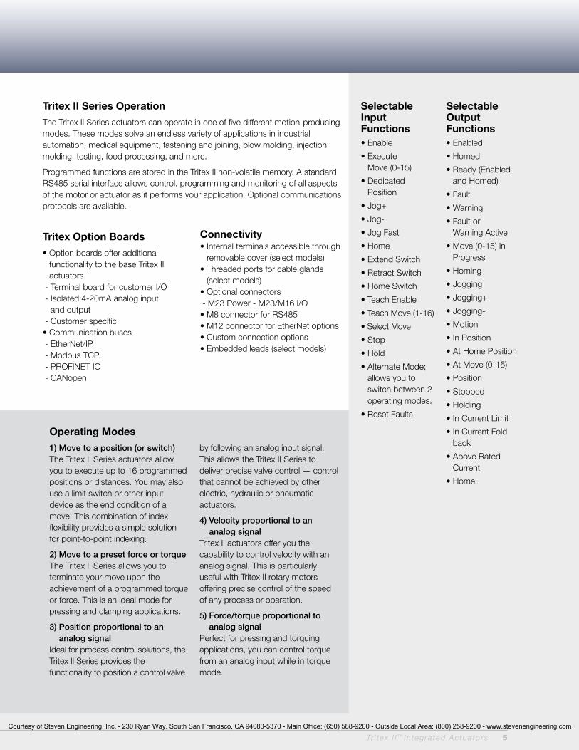
Tritex II Series Operation
The Tritex II Series actuators can operate in one of five different motion-producing modes. These modes solve an endless variety of applications in industrial automation, medical equipment, fastening and joining, blow molding, injection molding, testing, food processing, and more.
Programmed functions are stored in the Tritex II non-volatile memory. A standard RS485 serial interface allows control, programming and monitoring of all aspects of the motor or actuator as it performs your application. Optional communications protocols are available.
Tritex Option Boards
• Option boards offer additional functionality to the base Tritex II actuators
- Terminal board for customer I/O - Isolated 4-20mA analog input
and output - Customer specific• Communication buses - EtherNet/IP - Modbus TCP - PROFINET IO - CANopen
Connectivity• Internal terminals accessible through
removable cover (select models)• Threaded ports for cable glands
(select models)• Optional connectors - M23 Power - M23/M16 I/O • M8 connector for RS485• M12 connector for EtherNet options• Custom connection options• Embedded leads (select models)
Tr i tex I I ™ DC Powered In tegra ted Actua to rs 5
Selectable Input Functions• Enable
• Execute Move (0-15)
• Dedicated Position
• Jog+
• Jog-
• Jog Fast
• Home
• Extend Switch
• Retract Switch
• Home Switch
• Teach Enable
• Teach Move (1-16)
• Select Move
• Stop
• Hold
• Alternate Mode; allows you to switch between 2 operating modes.
• Reset Faults
Selectable Output Functions• Enabled
• Homed
• Ready (Enabled and Homed)
• Fault
• Warning
• Fault or Warning Active
• Move (0-15) in Progress
• Homing
• Jogging
• Jogging+
• Jogging-
• Motion
• In Position
• At Home Position
• At Move (0-15)
• Position
• Stopped
• Holding
• In Current Limit
• In Current Fold back
• Above Rated Current
• Home
Operating Modes
1) Move to a position (or switch) The Tritex II Series actuators allow you to execute up to 16 programmed positions or distances. You may also use a limit switch or other input device as the end condition of a move. This combination of index flexibility provides a simple solution for point-to-point indexing.
2) Move to a preset force or torque The Tritex II Series allows you to terminate your move upon the achievement of a programmed torque or force. This is an ideal mode for pressing and clamping applications.
3) Position proportional to an analog signal
Ideal for process control solutions, the Tritex II Series provides the functionality to position a control valve
by following an analog input signal. This allows the Tritex II Series to deliver precise valve control — control that cannot be achieved by other electric, hydraulic or pneumatic actuators.
4) Velocity proportional to an analog signal
Tritex II actuators offer you the capability to control velocity with an analog signal. This is particularly useful with Tritex II rotary motors offering precise control of the speed of any process or operation.
5) Force/torque proportional to analog signal
Perfect for pressing and torquing applications, you can control torque from an analog input while in torque mode.
Tr i tex I I ™ In tegra ted Actua to rs 5
Courtesy of Steven Engineering, Inc. - 230 Ryan Way, South San Francisco, CA 94080-5370 - Main Office: (650) 588-9200 - Outside Local Area: (800) 258-9200 - www.stevenengineering.com

Expert, the Tritex II user interface software,
provides you with a simple way to select all
aspects of configuration and control required
to set up and operate a Tritex II actuator.
Easy-to-use tabbed pages provide access to
input all of the parameters necessary to
successfully configure your motion application.
‘Application’ files give you a convenient way to
store and redistribute configurations amongst
multiple computers, and ‘Drive’ files allow the
same configuration to be distributed to multiple
Tritex II actuators. Motion setup, homing,
teach mode, tuning parameters, jogging, I/O
configuration, and local control are all
accomplished with ease using Expert software.
Expert User Interface
Protocol Options
The standard communication protocol for Tritex is an RS485 connection using Modbus RTU. The Modbus protocol provides a simple and robust method to connect industrial electronic devices on the same network. The Expert software acts as a Modbus Master and the Tritex II acts as the Slave device, only responding to requests commanded from the software. The Expert software allows full access to commissioning, configuring, monitoring and controlling the Tritex II.
In addition to Modbus RTU communications, the following protocol options are available by selecting communication option boards. Exlar requires initial commissioning of a Tritex II actuator to be performed with the Modbus protocol.
Modbus TCPModbus TCP couples Modbus communication structure from Modbus RTU with EtherNet connectivity. The Modbus TCP option is fully supported by the Expert software and offers seamless use for
commissioning, configuring, monitoring and controlling the Tritex II. A Modbus mapping table allows you to map all of the parameters you wish to read and modify into a register bank of up to 100 registers. This will allow a PLC program to perform a single read operation and a single write operation to all the parameters.
EtherNet/IPEtherNet/IP allows you to change, monitor and control the Tritex II through implicit or explicit messaging initiated from your Rockwell PLC. Tritex parameters are set up through the Expert software using a Tritex II parameter to EtherNet/IP parameter mapping table. Up to 100 input and 100 output 16 bit registers can be mapped to Tritex II parameters.
ProFINET IoPROFINET IO allows you to change, monitor and control the Tritex II from your Siemens PLC. Tritex parameters are set up through the Expert software using a Tritex II parameter to PROFINET IO parameter mapping table. Up to 100 input and 100 output 16 bit registers can be mapped to Tritex II parameters.
CANopenThe Tritex II with the CANopen network is intended to perform as a Slave receiving commands from a CANopen Master. It does not have all the features of a standalone indexer, like other Tritex models. CANopen Communication protocol DSP301 is supported as well as DSP 402 supporting Profile Torque, Profile Velocity, Profile Position and Homing. Setup on the system is most easily achieved with the Expert software using the RS485 port.
Modbus Mapping Screen
6 Tr i tex I I ™ In tegra ted Actua to rs
Courtesy of Steven Engineering, Inc. - 230 Ryan Way, South San Francisco, CA 94080-5370 - Main Office: (650) 588-9200 - Outside Local Area: (800) 258-9200 - www.stevenengineering.com
EtherNet IP Mapping Screen
Motion Setup
Exlar configuration provides several templates for various applications. These can serve as your configuration, or as a starting point for your configuration. You can also begin by selecting configuration details specific to your application. You can configure a move to position, move to switch, or move to force motion at the click of a button. The Tritex II products offer absolute and incremental motion, as well as moves ending on a condition such as a specific force or torque.
Control Page
The Expert control page gives you the ability to initiate all motion functions from one simple screen. This screen provides you with very easy system start-up and testing without all the inconvenience of machine wiring.
The control page offers the capability to enable and disable the drive and perform fast and slow jogs. This gives you the ability to verify motion before needing any I/O wiring.
Monitoring and Diagnostics
All input functions can be monitored and activated from the Expert monitor page, and all output functions can be monitored. Information on critical fault and status data is available as a separate page, or as a fixed window on the bottom of each page of the software.
Configuring I/O
A pull down menu allows all I/O to be set up in minutes. Inputs can be configured to be maintained, or momentary, depending on the application requirements. Input and output logic can also be inverted with a simple click.
Homing
You can home to an input, by using a proximity or limit switch, or home to a specific force or torque.
Homing to a force or torque is ideal for setting up applications that require motion referenced to a hard stop, like the closed position of a valve, or the final position of a press.
Teach Mode
In this mode, you can jog the actuator to the desired position, and activate an input, or click a button in the Expert software and the current position of the actuator becomes the defined distance or absolute position associated with a particular move command.
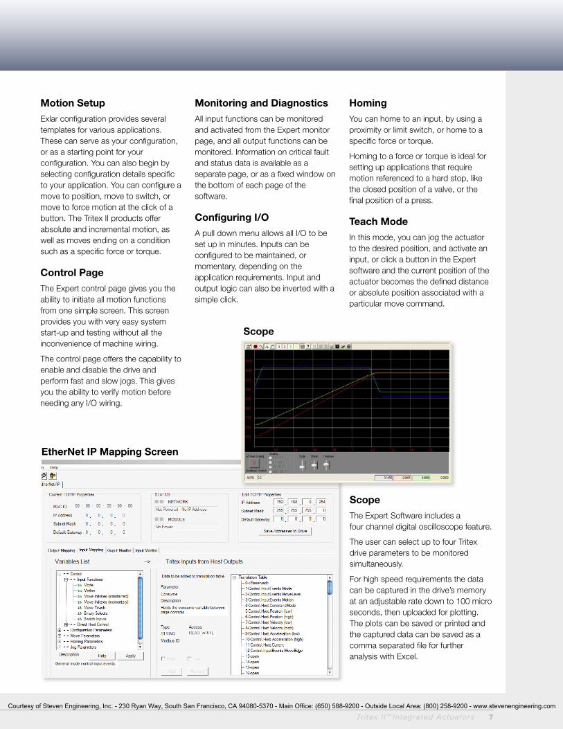
Scope
Scope
The Expert Software includes a four channel digital oscilloscope feature.
The user can select up to four Tritex drive parameters to be monitored simultaneously.
For high speed requirements the data can be captured in the drive’s memory at an adjustable rate down to 100 micro seconds, then uploaded for plotting. The plots can be saved or printed and the captured data can be saved as a comma separated file for further analysis with Excel.
Tr i tex I I ™ In tegra ted Actua to rs 7
Courtesy of Steven Engineering, Inc. - 230 Ryan Way, South San Francisco, CA 94080-5370 - Main Office: (650) 588-9200 - Outside Local Area: (800) 258-9200 - www.stevenengineering.com

Process Control Functionality
Precise valve and damper control is the perfect application for Tritex II actuators. They outperform other electric, hydraulic and pneumatic actuators by providing small hysteresis and dead band, quick response to small signal changes and stable dynamic responses.
Fully programmable to follow an analog or digital signal representing either position or force, the Tritex II linear actuator is perfectly designed for control valve applications with thrust requirements up to 3225 lbf or rotary torque applications up to 95 lbf-in continuous.
The Tritex II Rotary actuators are ideal for directly operating quarter-turn valves. Gear ratios of 4:1 to 100:1 allow the power of Tritex II to be applied to a broad range of applications, providing high turndown without loss of accuracy.
Tritex II actuators can be mounted on any valve from any manufacturer.
Valve Software
Our valve software is simple to use, featuring a teach mode for foolproof stroke configuration. Included is a programmable valve cut off position feature that enables a firm valve seat on either new valves, or retrofitted valves. Several diagnostics and auxiliary I/O options are also available.
Class I Division 2 Rating
Exlar’s Tritex II actuators are available for applications requiring CSA Class I Division 2 certification. Ordering a standard I/O interconnect with or without 4-20 mA Analog I/O, and the N option for the NPT port will provide you with Class I Division 2 rated product.
Extreme AccuracyThe Exlar actuators stroke the valve based on position, not air or oil pressure. Accuracy and repeatability are better than 0 .1%.
100% Duty CycleExlar’s unique way of converting rotary motor motion to a linear force using a roller screw provides full modulation capability. Life is measured in 100’s of million strokes vs. thousands like typical electric actuators.
Built in Positioner The Tritex II actuators from Exlar include a built in positioner with a 4-20 mA or digital signal to tell you the exact stroke position. An analog output is also available.
FlexibilityThe Tritex II actuators include digital I/O in addition to analog control. This provides the user with options for additional control such as emergency stop, +/- jog or various diagnostic conditions.
Low Power ConsumptionThe Tritex II actuator only uses the current needed for a given force. This extreme efficiency makes it suitable for use with solar panels and batteries.
Fast response and Stroke SpeedsMost other electric actuators are known for being slow — a major disadvantage.
Tritex II response rate is measured in milliseconds. Stoke speeds can be up to 33 in/sec.
Hydraulic replacementTritex actuators have the same capabilities as a hydraulic equivalent, but without the cost or maintenance issues. High force, fast speeds and precise movements make it a suitable substitute for hydraulic applications.
Absolute FeedbackThe absolute feedback option gives the actuator memory after teaching the valve limits. Upon power loss, the battery backup will maintain the valve limits.
Manual override Two optional are available. The hand wheel option gives you a manual engagement switch that can be used to disable the power to the actuator. The side drive option allows for emergency operation in a power down condition using a standard socket wrench.
DiagnosticsAll inputs and outputs can be monitored including position, temperature, current and many more. An oscilloscope feature is also included, allowing a user to select up to four parameters to be monitored simultaneously. The data can be captured in the drive’s memory at an adjustable rate down to 100 micro sec, and then uploaded for plotting.
8 Tr i tex I I ™ In tegra ted Actua to rs
Benefits for Process Control Applications
Courtesy of Steven Engineering, Inc. - 230 Ryan Way, South San Francisco, CA 94080-5370 - Main Office: (650) 588-9200 - Outside Local Area: (800) 258-9200 - www.stevenengineering.com
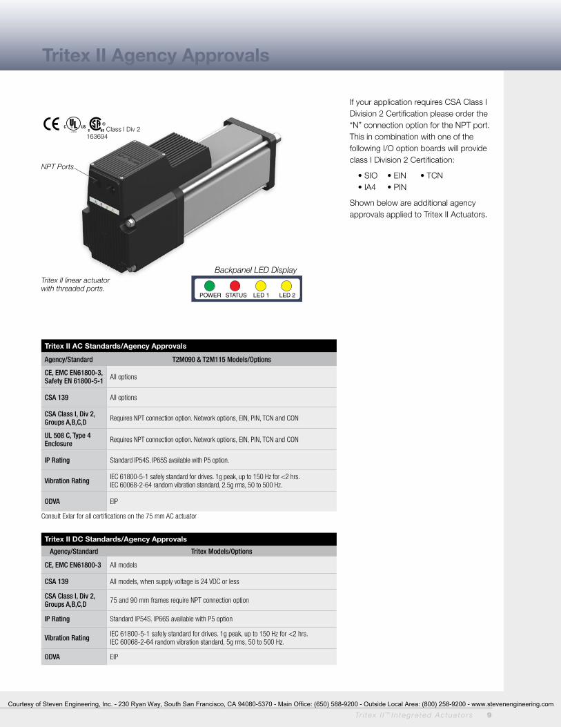
If your application requires CSA Class I Division 2 Certification please order the “N” connection option for the NPT port. This in combination with one of the following I/O option boards will provide class I Division 2 Certification:
• SIO • EIN • TCN • IA4 • PIN
Shown below are additional agency approvals applied to Tritex II Actuators.
Tritex II AC Standards/Agency Approvals
Agency/Standard T2M090 & T2M115 Models/Options
CE, EMC EN61800-3, Safety EN 61800-5-1 All options
CSA 139 All options
CSA Class I, Div 2, Groups A,B,C,D Requires NPT connection option. Network options, EIN, PIN, TCN and CON
UL 508 C, Type 4 Enclosure Requires NPT connection option. Network options, EIN, PIN, TCN and CON
IP Rating Standard IP54S. IP65S available with P5 option.
Vibration Rating IEC 61800-5-1 safely standard for drives. 1g peak, up to 150 Hz for <2 hrs.IEC 60068-2-64 random vibration standard, 2.5g rms, 50 to 500 Hz.
ODVA EIP
Consult Exlar for all certifications on the 75 mm AC actuator
Tritex II DC Standards/Agency Approvals
Agency/Standard Tritex Models/Options
CE, EMC EN61800-3 All models
CSA 139 All models, when supply voltage is 24 VDC or less
CSA Class I, Div 2, Groups A,B,C,D 75 and 90 mm frames require NPT connection option
IP Rating Standard IP54S. IP66S available with P5 option
Vibration Rating IEC 61800-5-1 safely standard for drives. 1g peak, up to 150 Hz for <2 hrs.IEC 60068-2-64 random vibration standard, 5g rms, 50 to 500 Hz.
ODVA EIP
Tritex II Agency Approvals
Tr i tex I I ™ In tegra ted Actua to rs 9
POWER STATUS LED 1 LED 2
Backpanel LED Display
163694Class I Div 2
Tritex II linear actuator with threaded ports.
NPT Ports
Courtesy of Steven Engineering, Inc. - 230 Ryan Way, South San Francisco, CA 94080-5370 - Main Office: (650) 588-9200 - Outside Local Area: (800) 258-9200 - www.stevenengineering.com
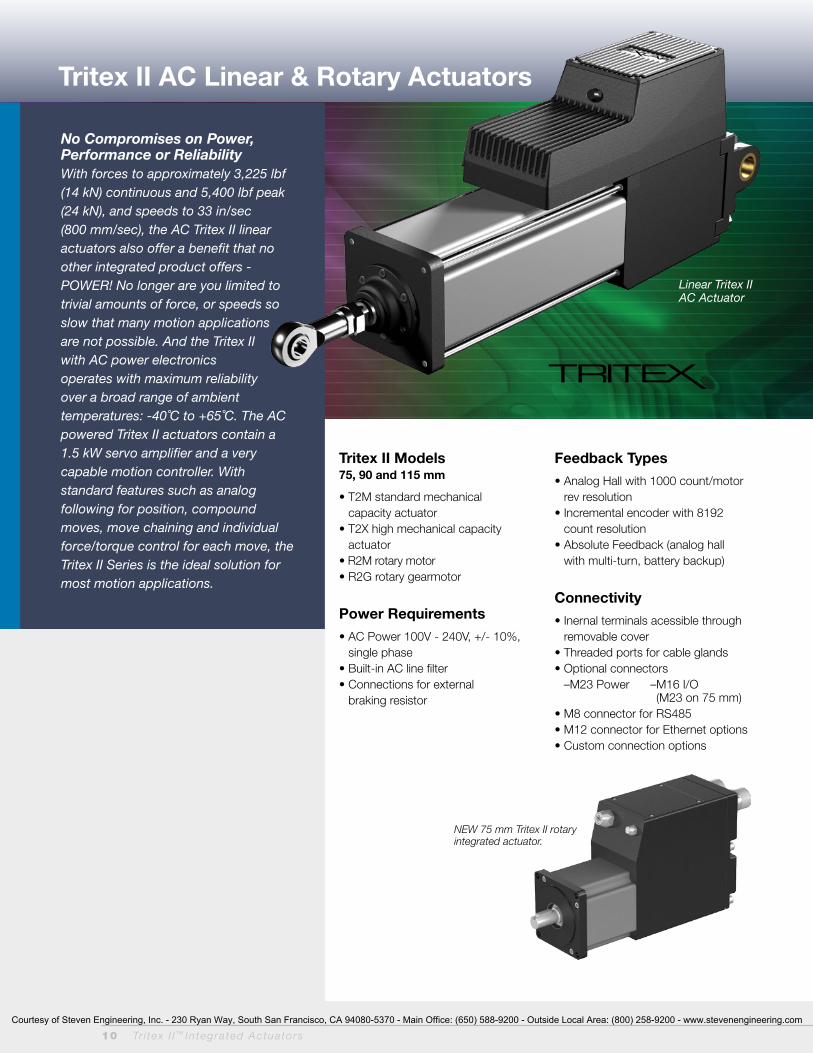
Tritex II AC Linear & Rotary Actuators
No Compromises on Power, Performance or ReliabilityWith forces to approximately 3,225 lbf (14 kN) continuous and 5,400 lbf peak (24 kN), and speeds to 33 in/sec (800 mm/sec), the AC Tritex II linear actuators also offer a benefit that no other integrated product offers - POWER! No longer are you limited to trivial amounts of force, or speeds so slow that many motion applications are not possible. And the Tritex II with AC power electronics operates with maximum reliability over a broad range of ambient temperatures: -40˚C to +65˚C. The AC powered Tritex II actuators contain a 1.5 kW servo amplifier and a very capable motion controller. With standard features such as analog following for position, compound moves, move chaining and individual force/torque control for each move, the Tritex II Series is the ideal solution for most motion applications.
Linear Tritex II AC Actuator
Tritex II Models 75, 90 and 115 mm
• T2M standard mechanical capacity actuator
• T2X high mechanical capacity actuator
• R2M rotary motor• R2G rotary gearmotor
Power Requirements
• AC Power 100V - 240V, +/- 10%, single phase
• Built-in AC line filter• Connections for external
braking resistor
Feedback Types
• Analog Hall with 1000 count/motor rev resolution
• Incremental encoder with 8192 count resolution
• Absolute Feedback (analog hall with multi-turn, battery backup)
Connectivity
• Inernal terminals acessible through removable cover
• Threaded ports for cable glands• Optional connectors
–M23 Power – M16 I/O (M23 on 75 mm)
• M8 connector for RS485• M12 connector for Ethernet options• Custom connection options
10 Tr i tex I I ™ In tegra ted Actua to rs
NEW 75 mm Tritex II rotary integrated actuator.
Courtesy of Steven Engineering, Inc. - 230 Ryan Way, South San Francisco, CA 94080-5370 - Main Office: (650) 588-9200 - Outside Local Area: (800) 258-9200 - www.stevenengineering.com
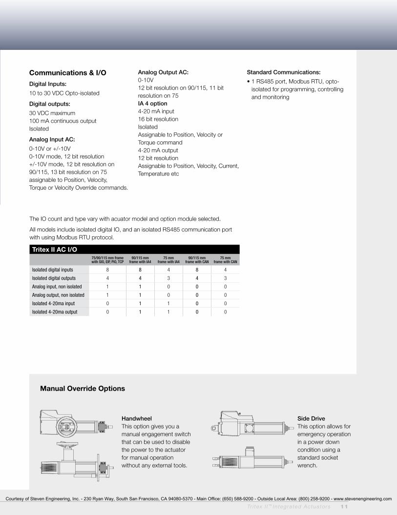
Manual Override Options
Handwheel This option gives you a manual engagement switch that can be used to disable the power to the actuator for manual operation without any external tools.
Communications & I/O
Digital Inputs:
10 to 30 VDC Opto-isolated
Digital outputs:
30 VDC maximum 100 mA continuous output Isolated
Analog Input AC:
0-10V or +/-10V0-10V mode, 12 bit resolution +/-10V mode, 12 bit resolution on 90/115, 13 bit resolution on 75 assignable to Position, Velocity, Torque or Velocity Override commands.
Analog output AC: 0-10V12 bit resolution on 90/115, 11 bit resolution on 75IA 4 option 4-20 mA input16 bit resolutionIsolatedAssignable to Position, Velocity or Torque command4-20 mA output12 bit resolutionAssignable to Position, Velocity, Current, Temperature etc
Standard Communications:
• 1 RS485 port, Modbus RTU, opto-isolated for programming, controlling and monitoring
The IO count and type vary with acuator model and option module selected.
All models include isolated digital IO, and an isolated RS485 communication port with using Modbus RTU protocol.
Tritex II AC I/O75/90/115 mm frame with SIO, EIP, PIO, TCP
90/115 mm frame with IA4
75 mm frame with IA4
90/115 mm frame with CAN
75 mm frame with CAN
Isolated digital inputs 8 8 4 8 4
Isolated digital outputs 4 4 3 4 3
Analog input, non isolated 1 1 0 0 0
Analog output, non isolated 1 1 0 0 0
Isolated 4-20ma input 0 1 1 0 0
Isolated 4-20ma output 0 1 1 0 0
Side Drive This option allows for emergency operation in a power down condition using a standard socket wrench.
Tr i tex I I ™ In tegra ted Actua to rs 11
Courtesy of Steven Engineering, Inc. - 230 Ryan Way, South San Francisco, CA 94080-5370 - Main Office: (650) 588-9200 - Outside Local Area: (800) 258-9200 - www.stevenengineering.com

12 Tr i tex I I ™ DC Powered In tegra ted Actua to rs
Travel LifeT2M/T2X Lifetime CurvesThe L10 expected life of a roller screw linear actuator is expressed as the linear travel distance that 90% of properly maintained roller screws manufactured are expected to meet or exceed. For higher than 90% reliability, the result should be multiplied by the following factors: 95% x 0.62; 96% x 0.53; 97% x 0.44; 98% x 0.33; 99% x 0.21. This is not a guarantee and these charts should be used for estimation purposes only.
The underlying formula that defines this value is:
Travel life in millions of inches, where:
C = Dynamic load rating (lbf)
F = Cubic mean applied load (lbf)
S = Roller screws lead (inches)
Extended TemperatureDe-Rating Curve; 90 and 115 mmThe speed/torque curves are based on 25˚ C ambient conditions. The actuators may be operated at ambient temperatures up to 65˚ C. Use the curve shown right for continuous torque/force deratings above 25˚ C.
All curves represent properly lubricated and maintained actuators.
L10 = ( C )3 x S F
Travel Life and Temperature Ratings
Dynamic Load RatingModel lb (N) Model lb (N)
T2M075/090-xx01 3310 (14724) T2X075/090-xx01 5516 (24536)
T2M075/090-xx02 3570 (15880) T2X075/090-xx02 5800 (25798)
T2M075/090-xx05 3016 (13416) T2X075/090-xx05 4900 (21795)
T2M115-xx01 4736 (21067) T2X115-xx01 7900 (35141)
T2M115-xx02 4890 (21751) T2X115-xx02 8300 (36920)
T2M115-xx05 4218 (18763) T2X115-xx05 7030 (31271)
T2M115-xx08 3328 (14804) T2X115-xx08 6335 (28179)
12 Tr i tex I I ™ In tegra ted Actua to rs
T2M/X075 and T2M/X090 Estimated L10 Travel Life T2M/X115 Estimated L10 Travel Life
% Stall Torque 120
100
80
60
40
20
0 -20 -15 -10 -5 0 5 10 15 20 25 30 35 40 45 50 55 60 65
Temp, Deg C
% of Available Stall Torque vs Ambient Temperature
115mm90mm 75mm
T2M/X075 and T2M/X090 Estimated L10 Travel Life
T2M/X115 Estimated L10 Travel Life
T2M115-xx01T2M115-xx02T2M115-xx05T2M115-xx08
6,000(26,689)
5,000(22,241)
4,000(17,793)
3,000(13,345)
2,000(8,896)
1,000(4,448)
0
T2X115-xx01T2X115-xx02T2X115-xx05T2X115-xx08
T2M075/T2M090-xx01T2M075/T2M090-xx02T2M075/T2M090-xx05
4,000(17,793)
3,500(15,569)
3,000(13,345)
2,500(11,120)
2,000(8,896)
1,500(6,672)
1,000(4,448)
500(2,224)
0 1 10 100 1,000 10,000 (25) (254) (2,540) (25,400) (254,000)
T2X075/T2X090-xx01T2X075/T2X090-xx02T2X075/T2X090-xx05
1 10 100 1,000 10,000 (25) (254) (2,540) (25,400) (254,000)
Th
rust
Lo
ad lb
f (N
)T
hru
st L
oad
lbf
(N)
Travel Life Millions of Inches (mm)
Travel Life Millions of Inches (mm)
Courtesy of Steven Engineering, Inc. - 230 Ryan Way, South San Francisco, CA 94080-5370 - Main Office: (650) 588-9200 - Outside Local Area: (800) 258-9200 - www.stevenengineering.com
Tr i tex I I ™ DC Powered In tegra ted Actua to rs 13
0
Speed inch/sec (mm/sec)
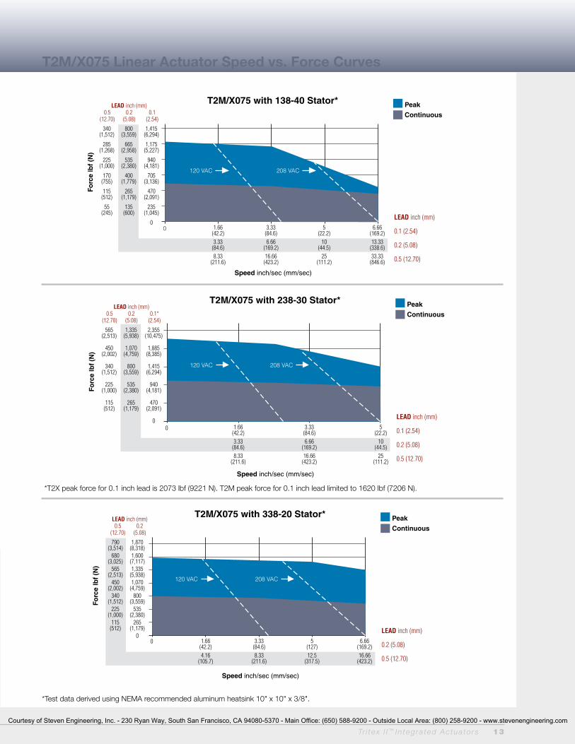
T2M/X075 with 238-30 Stator* Peak
Continuous
Forc
e lb
f (N
)
LEAD inch (mm) 0.5 0.2 0.1* (12.70) (5.08) (2.54)
1.66 3.33 5 (42.2) (84.6) (22.2) 3.33 6.66 10 (84.6) (169.2) (44.5) 8.33 16.66 25 (211.6) (423.2) (111.2)
LEAD inch (mm)
0.1 (2.54)
0.2 (5.08)
0.5 (12.70)
565 1,335 2,355 (2,513) (5,938) (10,475)
450 1,070 1,885 (2,002) (4,759) (8,385)
340 800 1,415 (1,512) (3,559) (6,294)
225 535 940 (1,000) (2,380) (4,181)
115 265 470 (512) (1,179) (2,091)
0
120 VAC 208 VAC
0
Speed inch/sec (mm/sec)
T2M/X075 with 338-20 Stator* Peak
Continuous
Forc
e lb
f (N
)
LEAD inch (mm) 0.5 0.2 (12.70) (5.08)
1.66 3.33 5 6.66 (42.2) (84.6) (127) (169.2) 4.16 8.33 12.5 16.66 (105.7) (211.6) (317.5) (423.2)
LEAD inch (mm)
0.2 (5.08)
0.5 (12.70)
790 1,870 (3,514) (8,318) 680 1,600 (3,025) (7,117) 565 1,335 (2,513) (5,938) 450 1,070 (2,002) (4,759) 340 800 (1,512) (3,559) 225 535 (1,000) (2,380) 115 265 (512) (1,179) 0
120 VAC 208 VAC
0
Speed inch/sec (mm/sec)
T2M/X075 with 138-40 Stator* Peak
Continuous
Forc
e lb
f (N
)
LEAD inch (mm) 0.5 0.2 0.1 (12.70) (5.08) (2.54)
1.66 3.33 5 6.66 (42.2) (84.6) (22.2) (169.2) 3.33 6.66 10 13.33 (84.6) (169.2) (44.5) (338.6) 8.33 16.66 25 33.33 (211.6) (423.2) (111.2) (846.6)
LEAD inch (mm)
0.1 (2.54)
0.2 (5.08)
0.5 (12.70)
340 800 1,415 (1,512) (3,559) (6,294)
285 665 1,175 (1,268) (2,958) (5,227)
225 535 940 (1,000) (2,380) (4,181)
170 400 705 (755) (1,779) (3,136)
115 265 470 (512) (1,179) (2,091)
55 135 235 (245) (600) (1,045)
0
120 VAC 208 VAC
T2M/X075 Linear Actuator Speed vs. Force Curves
Tr i tex I I ™ In tegra ted Actua to rs 13
*Test data derived using NEMA recommended aluminum heatsink 10" x 10" x 3/8".
*T2X peak force for 0.1 inch lead is 2073 lbf (9221 N). T2M peak force for 0.1 inch lead limited to 1620 lbf (7206 N).
Courtesy of Steven Engineering, Inc. - 230 Ryan Way, South San Francisco, CA 94080-5370 - Main Office: (650) 588-9200 - Outside Local Area: (800) 258-9200 - www.stevenengineering.com

14 Tr i tex I I ™ In tegra ted Actua to rs
0
T2M/X090 with 238-40 Stator*
Forc
e lb
f (N
)
1.66 3.33 5.00 6.66 (42.4) (84.6) (127.0) (169.4) 3.33 6.66 10.00 13.33 (84.6) (169.4) (254.0) (338.6) 8.33 16.66 25.00 33.33 (211.6) (423.4) (635.0) (846.6)
800 1,875 3,300 (3,559) (8,340) (14,679)
675 1,600 2,825 (3,003) (7,117) (12,566)
575 1,325 2,350 (2,558) (5,894) (10,453)
450 1,075 1,875 (2,000) (4,782) (8,340)
350 800 1,400 (1,557) (3,559) (6,228)
225 525 950 (1,000) (2,335) (4,225)
125 275 475 (556) (1,223) (2,113)
0
120 VAC 208 VAC
Peak
Continuous
LEAD inch (mm)
0.1 (2.54)
0.2 (5.08)
0.5 (12.70)
Speed inch/sec (mm/sec)
LEAD inch (mm) 0.5 0.2 0.1* (12.70) (5.08) (2.54)
0 3.33 6.66 10.00 (84.6) (169.4) (254.0) 8.33 16.66 25.00 (211.6) (423.4) (635.0)
1,025 2,400 (4,559) (10,675) 900 2,125 (4,003) (9,452) 800 1,875 (3,559) (8,340) 675 1,600 (3,003) (7,117) 575 1,325 (2,558) (5,894) 450 1,075 (2,000) (4,782) 350 800 (1,557) (3,559) 225 525 (1,000) (2,335) 125 275 (556) (1,223) 0
120 VAC 208 VAC
T2M/X090 with 238-30 Stator*
Forc
e lb
f (N
)
Peak
Continuous
LEAD inch (mm)
0.2 (5.08)
0.5 (12.70)
Speed inch/sec (mm/sec)
LEAD inch (mm) 0.5 0.2
(12.70) (5.08)
0
Speed inch/sec (mm/sec)
T2M/X090 with 138-40 Stator* Peak
ContinuousFo
rce
lbf
(N)
LEAD inch (mm) 0.5 0.2 0.1 (12.70) (5.08) (2.54)
1.66 3.33 5.00 6.66 (42.2) (84.6) (127) (169.4) 3.33 6.66 10.00 13.33 (84.6) (169.4) (254.0) (338.6) 8.33 16.66 25.00 33.33 (211.6) (423.4) (635.0) (846.6)
LEAD inch (mm)
0.1 (2.54)
0.2 (5.08)
0.5 (12.70)
675 1,600 2,825 (3,003) (7,117) (12,566)
575 1,325 2,350 (2,558) (5,894) (10,453)
450 1,075 1,875 (2,000) (4,782) (8,340)
350 800 1,400 (1,557) (3,559) (6,228)
225 525 950 (1,000) (2,335) (4,225)
125 275 475 (556) (1,223) (2,113)
0
120 VAC 208 VAC
T2M/X090 Linear Actuator Speed vs. Force Curves
*Test data derived using NEMA recommended aluminum heatsink 10" x 10" x 3/8".
*T2X peak force for 0.1 inch lead is 2700 lbf (12010 N). T2M peak force for 0.1 inch lead limited to 1620 lbf (7206 N).
Courtesy of Steven Engineering, Inc. - 230 Ryan Way, South San Francisco, CA 94080-5370 - Main Office: (650) 588-9200 - Outside Local Area: (800) 258-9200 - www.stevenengineering.com

Tr i tex I I ™ In tegra ted Actua to rs 15
0
Forc
e lb
f (N
)
LEAD inch (mm) 0.75 0.5 0.2 (19.05) (12.70) (5.08)
1.67 3.33 5.00 (42.4) (84.6) (127.0) 4.16 8.33 12.50 (105.7) (211.6) (317.5) 6.25 12.50 18.75 (159.0) (317.5) (476.3)
1,500 2,250 5,025 (6,672) (10,009) (22,350)
1,125 1,700 3,775 (5,004) (7,562) (16,792)
750 1,130 2,500 (3,336) (5,026) (11,120)
375 575 1,250 (1,668) (2,558) (5,560)
0
120 VAC 208 VAC
T2M/X115 with 238-15 Stator*Peak
Continuous
LEAD inch (mm)
0.2 (5.08)
0.5 (12.70)
0.75 (19.05)
Speed inch/sec (mm/sec)
T2M/X115 Linear Actuator Speed vs. Force Curves
0
T2M/X115 with 138-30 Stator*Fo
rce
lbf
(N)
LEAD inch (mm) 0.75 0.5 0.2 0.1 (19.05) (12.70) (5.08) (2.54)
.83 1.67 2.50 3.33 4.17 5.00 (21.1) (42.4) (63.5) (84.6) (105.9) (127.0) 1.67 3.33 5.00 6.67 8.33 10.00 (42.4) (84.6) (127.0) (169.4) (211.6) (254.0) 4.16 8.33 12.50 16.67 20.83 25.00 (105.7) (211.6) (317.5) (423.4) (529.1) (635.0) 6.25 12.50 18.75 25.00 31.25 37.50 (159.0) (317.5) (476.3) (635.0) (794.0) (952.5)
750 1,125 2,500 4,400 (3,336) (5,004) (11,120) (19,572)
600 900 2,000 3,525 (2,669) (4,003) (8,896) (15,680)
450 675 1,500 2,650 (2,002) (3,003) (6,672) (11,788)
300 450 1,000 1,750 (1,334) (4,225) (4,448) (7,784)
150 225 500 875 (667) (1,000) (2,224) (3,892)
0
120 VAC 208 VAC
Peak
Continuous
LEAD inch (mm)
0.1 (2.54)
0.2 (5.08)
0.5 (12.70)
0.75 (19.05)
Speed inch/sec (mm/sec)
0
Forc
e lb
f (N
)
.83 1.67 2.50 3.33 (21.1) (42.4) (63.5) (84.6) 1.67 3.33 5.00 6.67 (42.4) (84.6) (127.0) (169.4) 4.16 8.33 12.50 16.67 (105.7) (211.6) (317.5) (423.40 6.25 12.50 18.75 25.00 (159.0) (317.5) (476.3) (635.0)
1,200 1,800 4,025 7,025 (5,338) (8,007) (17,904) (31,244) 1,050 1,575 3,525 6,150 (4,670) (7,005) (15,680) (27,357) 900 1,350 3,000 5,275 (4,003) (5,300) (13,345) (23,464) 750 1,125 2,500 4,400 (3,336) (5,004) (11,120) (10,572) 600 900 2,000 3,525 (2,669) (4,003) (8,896) (15,680) 450 675 1,500 2,650 (2,002) (3,003) (6,672) (11,788) 300 450 1,000 1,750 (1,334) (4,225) (4,448) (7,784) 150 225 500 875 (667) (1,000) (2,224) (3,892) 0
T2M/X115 with 238-20 Stator* LEAD inch (mm) 0.75 0.5 0.2 0.1* (19.05) (12.70) (5.08) (2.54)
Peak
Continuous
LEAD inch (mm)
0.1 (2.54)
0.2 (5.08)
0.5 (12.70)
0.75 (19.05)
Speed inch/sec (mm/sec)
120 VAC 208 VAC
*Test data derived using NEMA recommended aluminum heatsink 12" x 12" x 1/2".
*T2X peak force for 0.1 inch lead is 5400 lbf (24020 N). T2M peak force for 0.1 inch lead limited to 3966 lbf (17,642 N).
Courtesy of Steven Engineering, Inc. - 230 Ryan Way, South San Francisco, CA 94080-5370 - Main Office: (650) 588-9200 - Outside Local Area: (800) 258-9200 - www.stevenengineering.com

16 Tr i tex I I ™ In tegra ted Actua to rs
R2M Rotary Motor Speed vs. Torque Curves
For R2G gearmotors, multiply torque by gear ratio and efficiency. Efficiencies: Divide speed by gear ratio; 1 Stage = 0.91, 2 Stage = 0.86
0 500 1,000 1,500 2,000 2,500 3,000
TorqueLbf-in (Nm)
R2M090 with 238-30 Stator*
Peak
Continuous
90.0(10.1)
80.0(9.0)60.0(6.8)50.0(5.6)40.0(4.5)30.0(3.4)20.0(2.3)10.0(1.1)
0
120 VAC 208 VAC
Motor RPM0 500 1,000 1,500 2,000 2,500 3,000
50.0(5.6)
40.0(4.5)
30.0(3.4)
20.0(2.3)
10.0(1.1)
0
TorqueLbf-in (Nm)
R2M075 with 238-30 Stator*
Peak
Continuous
120 VAC 208 VAC
Motor RPM
0 500 1,000 1,500 2,000
TorqueLbf-in (Nm)
R2M090 with 338-20 Stator*
Peak
Continuous
120.0(13.6)
100.0(11.3)
80.0(9.0)
60.0(6.8)
40.0(4.5)
20.0(2.3)
0
120 VAC 208 VAC
Motor RPM
0 1,000 2,000 3,000 4,000
Motor RPM
30.0(3.4)
25.0(2.8)
20.0(2.3)
15.0(1.7)
10.0(1.1)
5.0(0.6)
0
TorqueLbf-in (Nm)
R2M075 with 138-40 Stator*
Peak
Continuous
120 VAC 208 VAC
0 500 1,000 1,500 2,000 2,500 3,000 3,500 4,000
70.0 (7.9)
60.0 (6.8)
50.0 (5.6)
40.0 (4.5)
30.0 (3.4)
20.0 (2.3)
10.0 (1.1)
0
TorqueLbf-in (Nm)
R2M090 with 238-40 Stator*
Peak
Continuous
120 VAC 208 VAC
Motor RPM0 500 1,000 1,500 2,000 2,500 3,000
TorqueLbf-in (Nm)
R2M115 with 138-30 Stator*
Peak
Continuous
120 VAC 208 VAC
100.0 (11.3)
80.0 (9.0)
60.0 (6.8)
40.0 (4.5)
20.0 (2.3)
0
Motor RPM
0 500 1,000 1,500
TorqueLbf-in (Nm)
R2M115 with 238-15 Stator*
Peak
Continuous
200.0(22.6)
150.0(16.9)
100.0(11.3)
50.0(5.6)
0
120 VAC 208 VAC
Motor RPM
0 500 1,000 1,500 2,000
TorqueLbf-in (Nm)
R2M115 with 238-20 Stator*
Peak
Continuous
160.0(18.1)140.0(15.8)120.0(13.6)100.0(11.3)
80.0(9.0)60.0(6.8)40.0(4.5)20.0(2.3)
0
120 VAC 208 VAC
Motor RPM
* R2M075 and R2M090 test data derived using NEMA recommended aluminum heatsink 10" x 10" x 3/8".* R2M115 test data derived using NEMA recommended aluminum heatsink 12" x 12" x 1/2".
R2M075 R2M090 R2M115
120 VAC 208 VAC
0 500 1,000 1,500 2,000
70.0(7.9)
60.0(6.8)
50.0(5.6)
40.0(4.5)
30.0(3.4)
20.0(2.3)
10.0(1.1)
0
TorqueLbf-in (Nm)
R2M075 with 338-20 Stator*
Peak
Continuous
Motor RPM
Courtesy of Steven Engineering, Inc. - 230 Ryan Way, South San Francisco, CA 94080-5370 - Main Office: (650) 588-9200 - Outside Local Area: (800) 258-9200 - www.stevenengineering.com
Tr i tex I I ™ In tegra ted Actua to rs 17
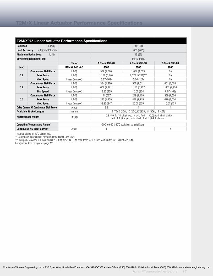
T2M/X Linear Actuator Performance Specifications
T2M/X075 Linear Actuator Performance SpecificationsBacklash in (mm) .008 (.20)
Lead Accuracy in/ft (mm/300 mm) .001 (.025)
Maximum Radial Load lb (N) 15 (67)
Environmental Rating: Std IP54 / IP65S
Stator 1 Stack 138-40 2 Stack 238-30 3 Stack 338-20
Lead RPM @ 240 VAC 4000 3000 2000
0.1Continuous Stall Force lbf (N) 589 (2,620) 1,037 (4,613) NA
Peak Force lbf (N) 1,178 (5,240) 2,073 (9,221)*** NA
Max. Speed in/sec (mm/sec) 6.67 (169) 5.00 (127) NA
0.2Continuous Stall Force lbf (N) 334 (1,486) 587 (2,611) 801 (3,563)
Peak Force lbf (N) 668 (2,971) 1,175 (5,227) 1,602 (7,126)
Ma. Speed in/sec (mm/sec) 13.33 (339) 10.00 (254) 6.67 (169)
0.5Continuous Stall Force lbf (N) 141 (627) 249 (1,108) 339 (1,508)
Peak Force lbf (N) 283 (1,259) 498 (2,215) 679 (3,020)
Max. Speed in/sec (mm/sec) 33.33 (847) 25.00 (635) 16.67 (423)
Drive Current @ Continuous Stall Force Amps 3.3 4 4
Available Stroke Lengths in (mm) 3 (76), 6 (150), 10 (254),12 (305), 14 (356), 18 (457)
Approximate Weight lb (kg) 10.8 (4.9) for 3 inch stroke, 1 stack. Add 1.1 (0.5) per inch of stroke. Add 1.1 (0.5) per motor stack. Add .8 (0.4) for brake.
Operating Temperature Range* -20C to 65C (-40˚C available, consult Exlar)
Continuous AC Input Current** Amps 4 5 5
* Ratings based on 40˚C conditions. ** Continuous input current rating is defined by UL and CSA.*** T2X peak force for 0.1 inch lead is 2073 lbf (9221 N). T2M peak force for 0.1 inch lead limited to 1620 lbf (7206 N).For dynamic load ratings see page 12.
Courtesy of Steven Engineering, Inc. - 230 Ryan Way, South San Francisco, CA 94080-5370 - Main Office: (650) 588-9200 - Outside Local Area: (800) 258-9200 - www.stevenengineering.com

18 Tr i tex I I ™ In tegra ted Actua to rs
T2M/X Linear Actuator Performance Specifications
T2M/X115 Linear Actuator Performance SpecificationsBacklash in (mm) .008 (.20)
Lead Accuracy in/ft (mm/300 mm) .001 (.025)
Maximum Radial Load lb (N) 15 (67)
Environmental Rating: Std IP54 / IP65S
Stator 1 Stack 138-30 2 Stack 238-20 2 Stack 238-15
Lead RPM @ 240 VAC 3000 2000 1500
0.1
Continuous Stall Force lbf (N) 2,060 (9,163) 3,224 (14,341) NA
Peak Stall Force lbf (N) 4,120 (18,327) 5,400 (24,020) NA
Max Speed in/sec (mm/sec) 5.00 (127) 3.33 (84) NA
0.2
Continuous Stall Force lbf (N) 1,177 (5,235) 1,843 (8,198) 2,380 (10,586)
Peak Stall Force lbf (N) 2,354 (10,471) 3,685 (16,392) 4,760 (21,174)
Max Speed in/sec (mm/sec) 10.00 (254) 6.67 (169) 5.00 (127)
0.5
Continuous Stall Force lbf (N) 530 (2,358) 829 (3,688) 1,071 (4,764)
Peak Stall Force lbf (N) 1,059 (4711) 1,658 (7,375) 2,142 (9,528)
Max Speed in/sec (mm/sec) 25.00 (635) 16.67 (423) 12.50 (317)
0.75
Continuous Stall Force lbf (N) 353 (1,570) 553 (2,460) 714 (3,176)
Peak Stall Force lbf (N) 706 (3,140) 1,106 (4,920) 1,428 (6,352)
Max Speed in/sec (mm/sec) 37.5 (953) 25 (635) 17.75 (450)
Drive Current @ Continuous Stall Force Amps 8.5 8.5 8.5
Available Stroke Lengths in (mm) 4 (102), 6 (150), 10 (254), 12 (300), 18 (450)
Approximate Weight lb (kg) 34 (15.5) for 6 inch stroke, 1 stack. Add 2 (1) per inch of stroke. Add 8 (4) per motor stack. Add 4 (2) for brake.
Operating Temperature Range* -20 to 65˚ C (-40˚C available, consult Exlar)
Continuous AC Input Current** Amps 8.3 8.3 8.3*Ratings based on 25˚C conditions. For dynamic load ratings see page 12. **Continuous input current rating is defined by UL and CSA.*** T2X peak force for 0.1 inch lead is 5400 lbf (24020 N). T2M peak force for 0.1 inch lead limited to 3966 lbf (17,642 N).
T2M/X090 Linear Actuator Performance SpecificationsBacklash in (mm) .008 (.20)
Lead Accuracy in/ft (mm/300 mm) .001 (.025)
Maximum Radial Load lb (N) 15 (67)
Environmental Rating: Std IP54 / IP65S
Stator 1 Stack 138-40 2 Stack 238-40 2 Stack 238-30
Lead RPM @ 240 VAC 4000 4000 3000
0.1Continuous Stall Force lbf (N) 1,130 (5062) 1,488 (6619) NA
Peak Stall Force lbf (N) 2,260 (10053) 2,700 (12010)*** NA
Max Speed in/sec (mm/sec) 6.67 (169) 6.67 (169) NA
0.2Continuous Stall Force lbf (N) 640 (2847) 843 (3750) 1,113 (4951)
Peak Stall Force lbf (N) 1,281 (5698) 1,687 (7504) 2,225 (9897)
Max Speed in/sec (mm/sec) 13.33 (338) 13.33 (338) 10.00 (254)
0.5Continuous Stall Force lbf (N) 271 (1205) 357 (1588) 471 (2095)
Peak Stall Force lbf (N) 542 (2410) 714 (3176) 942 (4190)
Max Speed in/sec (mm/sec) 33.33 (846) 33.33 (846) 25.00 (635)
Drive Current @ Continuous Stall Force Amps 5.7 7.5 7.5
Available Stroke Lengths in (mm) 3 (75), 6 (150), 10 (254), 12 (300), 18 (450)
Approximate Weight lb (kg) 14 (6.35) for 3 inch stroke, 1 stack. Add 1 (0.5) per inch of stroke. Add 3 (1.4) per motor stack. Add 3 (1.4) for brake.
Operating Temperature Range* -20 to 65˚ C (-40˚C available, consult Exlar)
Continuous AC Input Current** Amps 6.3 6.3 6.3*Ratings based on 25˚C conditions. For dynamic load ratings see page 12.**Continuous input current rating is defined by UL and CSA.*** T2X peak force for 0.1 inch lead is 2700 lbf (12010 N). T2M peak force for 0.1 inch lead limited to 1620 lbf (7206 N).
Courtesy of Steven Engineering, Inc. - 230 Ryan Way, South San Francisco, CA 94080-5370 - Main Office: (650) 588-9200 - Outside Local Area: (800) 258-9200 - www.stevenengineering.com
Tr i tex I I ™ In tegra ted Actua to rs 19
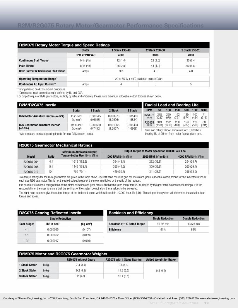
R2M/R2G075 Inertia Stator 1 Stack 2 Stack 3 Stack
R2M Motor Armature Inertia (+/-5%) lb-in-sec2
(kg-cm2)0.000545(0.6158)
0.000973 (1.0996)
0.001401 (1.5834)
R2G Gearmotor Armature Inertia*(+/-5%)
lbf-in-sec2
(kg-cm2)0.000660(0.7450)
0.001068(1.2057)
0.001494(1.6868)
*Add armature inertia to gearing inertia for total R2G system inertia.
Radial Load and Bearing LifeRPM 50 100 250 500 1000 3000
R2M075lbf (N)
278(1237)
220 (979)
162 (721)
129 (574)
102 (454)
71 (316)
R2G075 lbf (N)
343 (1526)
272 (1210)
200 (890)
159 (707)
126 (560)
88 (391)
Side load ratings shown above are for 10,000 hour bearing life at 25mm from motor face at given rpm.
R2G075 Gearing Reflected InertiaSingle Reduction
Gear Stages lbf-in-sec2 (kg-cm2)
4:1 0.000095 (0.107)
5:1 0.000062 (0.069)
10:1 0.000017 (0.019)
Backlash and EfficiencySingle Reduction Double Reduction
Backlash at 1% Rated Torque 10 Arc min 13 Arc min
Efficiency 91% 86%
R2M075 Motor and R2G075 Gearmotor WeightsR2M075 without Gears R2G075 with 1 Stage Gearing Added Weight for Brake
1 Stack Stator lb (kg) 7.4 (3.4) 9.8 (4.4)
0.8 (0.4)2 Stack Stator lb (kg) 9.2 (4.2) 11.6 (5.3)
3 Stack Stator lb (kg) 11 (4.9) 13.4 (6.1)
R2M/R2G115R2M075 Rotary Motor Torque and Speed RatingsStator 1 Stack 138-40 2 Stack 238-30 2 Stack 238-20
RPM at 240 VAC 4000 3000 2000
Continuous Stall Torque lbf-in (Nm) 12 (1.4) 22 (2.5) 30 (3.4)
Peak Torque lbf-in (Nm) 25 (2.8) 44 (4.9) 60 (6.8)
Drive Current @ Continuous Stall Torque Amps 3.3 4.0 4.0
Operating Temperature Range* -20 to 65˚ C (-40˚C available, consult Exlar)
Continuous AC Input Current** Amps 4 5 5
*Ratings based on 40˚C ambient conditions. **Continuous input current rating is defined by UL and CSA. For output torque of R2G gearmotors, multiply by ratio and efficiency. Please note maximum allowable output torques shown below.
R2M/R2G075 Rotary Motor/Gearmotor Performance Specifications
R2G075 Gearmotor Mechanical Ratings
Maximum Allowable Output Torque-Set by User lbf-in (Nm)
Output Torque at Motor Speed for 10,000 Hour Life
Model Ratio 1000 RPM lbf-in (Nm) 2500 RPM lbf-in (Nm) 4000 RPM lbf-in (Nm)
R2G075-004 4:1 1618 (182.8) 384 (43.4) 292 (32.9) 254 (28.7)
R2G075-005 5:1 1446 (163.4) 395 (44.6) 300 (33.9) 260 (29.4)
R2G075-010 10:1 700 (79.1) 449 (50.7) 341 (38.5) 296 (33.9)
Two torque ratings for the R2G gearmotors are given in the table above. The left hand columns give the maximum (peak) allowable output torque for the indicated ratios of each size R2G gearmotor. This is not the rated output torque of the motor multiplied by the ratio of the reducer.It is possible to select a configuration of the motor selection and gear ratio such that the rated motor torque, multiplied by the gear ratio exceeds these ratings. It is the responsibility of the user to ensure that the settings of the system do not allow these values to be exceeded.The right hand columns give the output torque at the indicated speed which will result in 10,000 hour life (L10). The setup of the system will determine the actual output torque and speed.
Courtesy of Steven Engineering, Inc. - 230 Ryan Way, South San Francisco, CA 94080-5370 - Main Office: (650) 588-9200 - Outside Local Area: (800) 258-9200 - www.stevenengineering.com
20 Tr i tex I I ™ In tegra ted Actua to rs
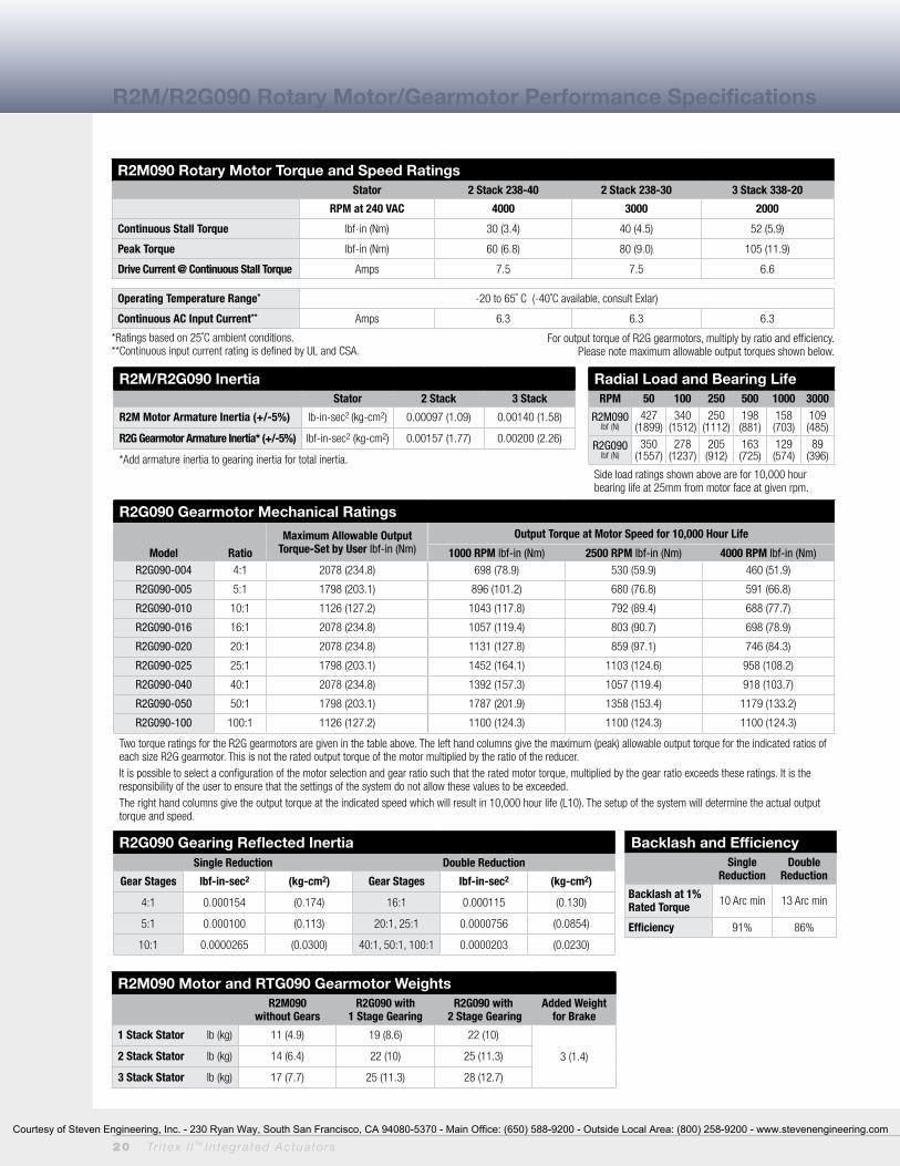
R2M090 Rotary Motor Torque and Speed RatingsStator 2 Stack 238-40 2 Stack 238-30 3 Stack 338-20
RPM at 240 VAC 4000 3000 2000
Continuous Stall Torque lbf-in (Nm) 30 (3.4) 40 (4.5) 52 (5.9)
Peak Torque lbf-in (Nm) 60 (6.8) 80 (9.0) 105 (11.9)
Drive Current @ Continuous Stall Torque Amps 7.5 7.5 6.6
Operating Temperature Range* -20 to 65˚ C (-40˚C available, consult Exlar)
Continuous AC Input Current** Amps 6.3 6.3 6.3
*Ratings based on 25˚C ambient conditions. **Continuous input current rating is defined by UL and CSA.
R2M/R2G090 Inertia Stator 2 Stack 3 Stack
R2M Motor Armature Inertia (+/-5%) lb-in-sec2 (kg-cm2) 0.00097 (1.09) 0.00140 (1.58)
R2G Gearmotor Armature Inertia* (+/-5%) lbf-in-sec2 (kg-cm2) 0.00157 (1.77) 0.00200 (2.26)
*Add armature inertia to gearing inertia for total inertia.
Radial Load and Bearing LifeRPM 50 100 250 500 1000 3000
R2M090lbf (N)
427(1899)
340 (1512)
250 (1112)
198 (881)
158 (703)
109 (485)
R2G090 lbf (N)
350 (1557)
278 (1237)
205 (912)
163 (725)
129 (574)
89 (396)
Side load ratings shown above are for 10,000 hour bearing life at 25mm from motor face at given rpm.
R2G090 Gearmotor Mechanical Ratings
Maximum Allowable Output Torque-Set by User lbf-in (Nm)
Output Torque at Motor Speed for 10,000 Hour Life
Model Ratio 1000 RPM lbf-in (Nm) 2500 RPM lbf-in (Nm) 4000 RPM lbf-in (Nm)
R2G090-004 4:1 2078 (234.8) 698 (78.9) 530 (59.9) 460 (51.9)
R2G090-005 5:1 1798 (203.1) 896 (101.2) 680 (76.8) 591 (66.8)
R2G090-010 10:1 1126 (127.2) 1043 (117.8) 792 (89.4) 688 (77.7)
R2G090-016 16:1 2078 (234.8) 1057 (119.4) 803 (90.7) 698 (78.9)
R2G090-020 20:1 2078 (234.8) 1131 (127.8) 859 (97.1) 746 (84.3)
R2G090-025 25:1 1798 (203.1) 1452 (164.1) 1103 (124.6) 958 (108.2)
R2G090-040 40:1 2078 (234.8) 1392 (157.3) 1057 (119.4) 918 (103.7)
R2G090-050 50:1 1798 (203.1) 1787 (201.9) 1358 (153.4) 1179 (133.2)
R2G090-100 100:1 1126 (127.2) 1100 (124.3) 1100 (124.3) 1100 (124.3)
Two torque ratings for the R2G gearmotors are given in the table above. The left hand columns give the maximum (peak) allowable output torque for the indicated ratios of each size R2G gearmotor. This is not the rated output torque of the motor multiplied by the ratio of the reducer.It is possible to select a configuration of the motor selection and gear ratio such that the rated motor torque, multiplied by the gear ratio exceeds these ratings. It is the responsibility of the user to ensure that the settings of the system do not allow these values to be exceeded.The right hand columns give the output torque at the indicated speed which will result in 10,000 hour life (L10). The setup of the system will determine the actual output torque and speed.
R2M/R2G090 Rotary Motor/Gearmotor Performance Specifications
R2G090 Gearing Reflected InertiaSingle Reduction Double Reduction
Gear Stages lbf-in-sec2 (kg-cm2) Gear Stages lbf-in-sec2 (kg-cm2)
4:1 0.000154 (0.174) 16:1 0.000115 (0.130)
5:1 0.000100 (0.113) 20:1, 25:1 0.0000756 (0.0854)
10:1 0.0000265 (0.0300) 40:1, 50:1, 100:1 0.0000203 (0.0230)
Backlash and EfficiencySingle
ReductionDouble
Reduction
Backlash at 1% Rated Torque 10 Arc min 13 Arc min
Efficiency 91% 86%
R2M090 Motor and RTG090 Gearmotor WeightsR2M090
without GearsR2G090 with
1 Stage GearingR2G090 with
2 Stage GearingAdded Weight
for Brake
1 Stack Stator lb (kg) 11 (4.9) 19 (8.6) 22 (10)
3 (1.4)2 Stack Stator lb (kg) 14 (6.4) 22 (10) 25 (11.3)
3 Stack Stator lb (kg) 17 (7.7) 25 (11.3) 28 (12.7)
For output torque of R2G gearmotors, multiply by ratio and efficiency. Please note maximum allowable output torques shown below.
Courtesy of Steven Engineering, Inc. - 230 Ryan Way, South San Francisco, CA 94080-5370 - Main Office: (650) 588-9200 - Outside Local Area: (800) 258-9200 - www.stevenengineering.com

Tr i tex I I ™ In tegra ted Actua to rs 21
R2M/R2G115 Inertia Stator 1 Stack 2 Stack
R2M Motor Armature Inertia (+/-5%) lb-in-sec2 (kg-cm2) 0.00344 (3.89) 0.00623 (7.036)
R2G Gearmotor Armature Inertia* lbf-in-sec2 (kg-cm2) 0.00538 (6.08) 0.00816 (9.22)
*Add armature inertia to gearing inertia for total R2M system inertia.
Radial Load and Bearing LifeRPM 50 100 250 500 1000 3000
R2M115lbf (N)
579(2576)
460 (2046)
339 (1508)
269 (1197)
214 (952)
148 (658)
R2G115 lbf (N)
858 (3817)
681 (3029)
502 (2233)
398 (1770)
316 (1406)
218 (970)
Side load ratings shown above are for 10,000 hour bearing life at 25mm from motor face at given rpm.
R2G115 Gearing Reflected InertiaSingle Reduction Double Reduction
Gear Stages lbf-in-sec2 (kg-cm2) Gear Stages lbf-in-sec2 (kg-cm2)
4:1 0.000635 (0.717) 16:1 0.000513 (0.580)
5:1 0.000428 (0.484) 20:1, 25:1 0.000350 (0.396)
10:1 0.000111 (0.125) 40:1, 50:1, 100:1 0.0000911 (0.103)
Backlash and EfficiencySingle
ReductionDouble
Reduction
Backlash at 1% Rated Torque 10 Arc min 13 Arc min
Efficiency 91% 86%
R2M115 Motor and RTG115 Gearmotor WeightsR2M115
without GearsR2G115 with
1 Stage GearingR2G115 with
2 Stage GearingAdded Weight
for Brake
1 Stack Stator lb (kg) 19 (8.6) 34 (15.4) 40 (18.1)
4 (2)2 Stack Stator lb (kg) 27 (12.2) 42 (19.1) 48 (21.8)
3 Stack Stator lb (kg) 35 (15.9) 50 (22.7) 56 (25.4)
R2M/R2G115R2M115 Rotary Motor Torque and Speed RatingsStator 1 Stack 138-30 2 Stack 238-20 2 Stack 238-15
RPM at 240 VAC 3000 2000 1500
Continuous Stall Torque lbf-in (Nm) 47 (5.3) 73 (8.3) 95 (10.7)
Peak Torque lbf-in (Nm) 94 (10.6) 146 (16.5) 190 (21.5)
Drive Current @ Continuous Stall Torque Amps 8.5 8.5 8.5
Operating Temperature Range* -20 to 65˚ C (-40˚C available, consult Exlar)
Continuous AC Input Current** Amps 8.3 8.3 8.3
*Ratings based on 25˚C ambient conditions. **Continuous input current rating is defined by UL and CSA.
R2M/R2G115 Rotary Motor/Gearmotor Performance Specifications
R2G115 Gearmotor Mechanical Ratings
Maximum Allowable Output Torque-Set by User lbf-in (Nm)
Output Torque at Motor Speed for 10,000 Hour Life
Model Ratio 1000 RPM lbf-in (Nm) 2000 RPM lbf-in (Nm) 3000 RPM lbf-in (Nm)
R2G115-004 4:1 4696 (530.4) 1392 (157.3) 1132 (127.9) 1000 (112.9)
R2G115-005 5:1 4066 (459.4) 1455 (163.3) 1175 (132.8) 1040 (117.5)
R2G115-010 10:1 2545 (287.5) 1660 (187.6) 1350 (152.6) 1200 (135.6)
R2G115-016 16:1 4696 (530.4) 2112 (238.6) 1714 (193.0) 1518 (171.0)
R2G115-020 20:1 4696 (530.4) 2240 (253.1) 1840 (207.9) 1620 (183.0)
R2G115-025 25:1 4066 (459.4) 2350 (265.5) 1900 (214.7) 1675 (189.2)
R2G115-040 40:1 4696 (530.4) 2800 (316.4) 2240 (253.1) 2000 (225.9)
R2G115-050 50:1 4066 (459.4) 2900 (327.7) 2350 (265.5) 2100 (237.3)
R2G115-100 100:1 2545 (287.5) 2500 (282.5) 2500 (282.5) 2400 (271.2)
Two torque ratings for the R2G gearmotors are given in the table above. The left hand columns give the maximum (peak) allowable output torque for the indicated ratios of each size R2G gearmotor. This is not the rated output torque of the motor multiplied by the ratio of the reducer.It is possible to select a configuration of the motor selection and gear ratio such that the rated motor torque, multiplied by the gear ratio exceeds these ratings. It is the responsibility of the user to ensure that the settings of the system do not allow these values to be exceeded.The right hand columns give the output torque at the indicated speed which will result in 10,000 hour life (L10). The setup of the system will determine the actual output torque and speed.
For output torque of R2G gearmotors, multiply by ratio and efficiency. Please note maximum allowable output torques shown below.
Courtesy of Steven Engineering, Inc. - 230 Ryan Way, South San Francisco, CA 94080-5370 - Main Office: (650) 588-9200 - Outside Local Area: (800) 258-9200 - www.stevenengineering.com
22 Tr i tex I I ™ In tegra ted Actua to rs
1.5238.7
1.5238.7
3.0577.4
5.30134.5
.215.3
3.54
89.8 BC
.256.4
1
.9624.4
1.3233.5
.235.8
2.000+-
.000
.003
50.80 -0.000.08
Dim "B"
Dim "A" "J" & "K" = 6mm +.000/-.013 6mm"S" & "D" = .2500 +.0000/-.0005 .250
"S" & "D" = 1/4-20 UNC"J" & "K" = M6 x 1.0
"S" & "J" = 4X, "D" & "K" = 8X
1.7544.5
"E" = 1/4-20 UNC"M" = M6 x 1.0
ALTERNATE CONNECTION LOCATION (SHOWN WITH PLUGS) .75
19 .75
19
4.58116.4
OPTION "G" CONNECTION SHOWNM20 x 1.5
3.0577.4
5.92150.4
3.9299.6
3.0577.4
Dim "C" 1.00
25.3
1.3233.5
"T" = 1.000 .001"Q" = 25mm .03
1.50038.1
Dim "A"
Dim "D"
R .75019.1
"C" = .750 +.002/-.001"G" = 20mm +.00/-.07mm
1.2331.3
OPTION "I"CONNECTION SHOWNM23 x 1
5.64143.3
4.96126.0
2.4863.0
3.0577.4
.4010.1
3.94100.0
1.9750.0
4X .246
1.3233.5
.5614.2
.5614.2
Dim "A"
.6717.0
OPTION "N"CONNECTION SHOWN1/2 NPT
5.64143.3
4.96126.0
2.4863.0
3.0577.4
.4010
3.94100.0
1.9750.0
4X .246
1.2531.8
2.5665.0
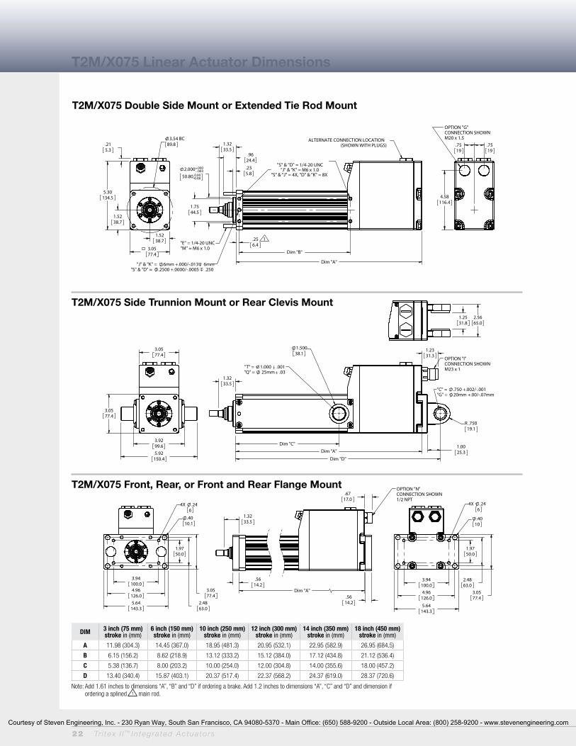
T2M/X075 Linear Actuator Dimensions
T2M/X075 Double Side Mount or Extended Tie Rod Mount
T2M/X075 Side Trunnion Mount or Rear Clevis Mount
T2M/X075 Front, Rear, or Front and Rear Flange Mount
DIM 3 inch (75 mm) stroke in (mm)
6 inch (150 mm) stroke in (mm)
10 inch (250 mm) stroke in (mm)
12 inch (300 mm) stroke in (mm)
14 inch (350 mm) stroke in (mm)
18 inch (450 mm) stroke in (mm)
A 11.98 (304.3) 14.45 (367.0) 18.95 (481.3) 20.95 (532.1) 22.95 (582.9) 26.95 (684.5)
B 6.15 (156.2) 8.62 (218.9) 13.12 (333.2) 15.12 (384.0) 17.12 (434.8) 21.12 (536.4)
C 5.38 (136.7) 8.00 (203.2) 10.00 (254.0) 12.00 (304.8) 14.00 (355.6) 18.00 (457.2)
D 13.40 (340.4) 15.87 (403.1) 20.37 (517.4) 22.37 (568.2) 24.37 (619.0) 28.37 (720.6)
Note: Add 1.61 inches to dimensions “A”, “B” and “D” if ordering a brake. Add 1.2 inches to dimensions “A”, “C” and “D” and dimension if ordering a splined 1 main rod.
Courtesy of Steven Engineering, Inc. - 230 Ryan Way, South San Francisco, CA 94080-5370 - Main Office: (650) 588-9200 - Outside Local Area: (800) 258-9200 - www.stevenengineering.com

Tr i tex I I ™ In tegra ted Actua to rs 23
3.54
901.77
45
1.77
45
3.54
90
4.13 B.C.
105
Single Side MountOn This Side
2.20
56
2.362 - .003+.000
60 - 0.080
.20
5.1
1.32
33.5
.96
24.4
Dim "B"
Dim "A"
2.15
54.6
6.95
176
.25 1
6.4"E" = 1/4-20 UNC"M" = M6x1.0
"J" & "K" = 6mm +.000-.013 6mm
"S" & "D" = .2500 +.0000-.0005 .250
RS485
"S" & "D" = 1/4-20 UNC"J" & "K" = M6x1.0"S" & "J" = 4X, "D" & "K" = 8X
3.54
90
3.54
90
1.00
25.4
4.42
112.1
6.42
162.9
1.32
33.5
1.50
38.1
1.250
31.8
R .75
19.1
Dim "A"
Dim "C"
Dim "D"
"T" = 1.000 .001
"Q" = 25mm .03
RS485
7.87
200
6.69
170
3.54
902.36
60
4.72
120
4X .57
14.5
4X .24
6
1.32
33.5
.44
11.1 Dim "A"
.49
12.4
1.3033
RS485 OPTION "I"CONNECTION SHOWNM23 x 1, M16 x 0.75
7.87200
6.69170
2.36
60
3.5490
4X .57
14.5
4X .24
6
1.2531.8
1.25
31.8
2.50
63.5
1.25
31.8
3.74
95
THREADED PORTCONNECTION SHOWNOPTION "G" = M20 x 1.5OPTION "N" = 1/2 NPT
(Rear View)
"C" = .750 +.000-.001
"G" = 20mm +.000-.025
T2M/X090 Linear Actuator Dimensions
T2M/X090 Double Side Mount or Extended Tie Rod Mount
T2M/X090 Side Trunnion Mount or Rear Clevis Mount
T2M/X090 Front, Rear, or Front and Rear Flange Mount
DIM 3 inch (75 mm) stroke in (mm)
6 inch (150 mm) stroke in (mm)
10 inch (250 mm) stroke in (mm)
12 inch (300 mm) stroke in (mm)
18 inch (450 mm) stroke in (mm)
A 11.54 (293.1) 14.01 (355.9) 18.53 (470.7) 20.53 (521.5) 26.53 (673.9)
B 6.15 (156.1) 8.62 (218.9) 13.12 (333.3) 15.12 (434.8) 21.12 (536.4)
C 5.38 (136.7) 8.01 (203.4) 10.00 (254.0) 12.00 (304.8) 18.00 (457.2)
D 13.52 (343.3) 15.99 (406.1) 20.49 (520.4) 22.49 (571.2) 28.49 (723.6)
Note: Add 1.61 inches to dimensions “A”, “B” and “D” if ordering a brake. Add 1.78 inches to dimensions “A”, “C” and “D” and dimension if ordering a splined 1 main rod.
Courtesy of Steven Engineering, Inc. - 230 Ryan Way, South San Francisco, CA 94080-5370 - Main Office: (650) 588-9200 - Outside Local Area: (800) 258-9200 - www.stevenengineering.com
24 Tr i tex I I ™ In tegra ted Actua to rs
5.12 BC
130
2.26
57.5
4.53
115
4.53
115
2.26
57.5
Single Side MountOn This Side
2.26
57.5
2.756 - .003+.000
70 - 0.080
2.6066
1.3835.1
1.6541.9
.205.1
7.56
192
Dim "B"
Dim "A"
.31 1
7.9
"E" = 3/8-16 UNC"M" = M8x1.25
"S" & "D" = 5/16-18 UNC"J" & "K" = M8x1.25"S" & "J" = 4X, "D" & "K" = 8X
"J" & "K" = 8mm +.000-.013 10mm
"S" & "D" = .3750 +.0000-.0005 .438
RS485
5.53
140.3
1.00
25.4
7.53
191.1
4.53
115
4.53
115
1.65
41.9
Dim "C"
2.00
50.8
Dim "A"
Dim "D"
R .75
19.1
"T" = 1.500 .001
"Q" = 35mm .03RS485
8.27
210
6.30
160
3.15
80
4.53
115
4X .31
8
4X .57
14.5
9.84
250
.63
15.9
1.65
41.9
.68
17.1Dim "A"
1.30
33
RS485
OPTION "I"
CONNECTION SHOWN
M23 x 1, M16 x 0.75
8.27
210 9.84
250
3.15
80
4.53
115
4X .57
14.54X .31
8
1.25
31.8
1.2531.75
2.5063.5
1.2531.8
4.24
107.7
THREADED PORTCONNECTION SHOWNOPTION "G" = M20 x 1.5OPTION "N" = 1/2 NPT
(Rear View)
"C" = .750 +.000-.001
"G" = 20mm +.000-.025
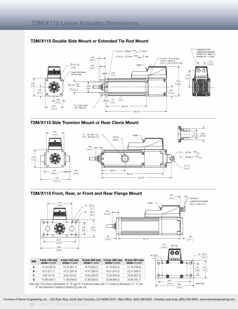
T2M/X115 Linear Actuator Dimensions
T2M/X115 Double Side Mount or Extended Tie Rod Mount
T2M/X115 Side Trunnion Mount or Rear Clevis Mount
T2M/X115 Front, Rear, or Front and Rear Flange Mount
DIM 4 inch (102 mm) stroke in (mm)
6 inch (152 mm) stroke in (mm)
10 inch (254 mm) stroke in (mm)
12 inch (305 mm) stroke in (mm)
18 inch (457 mm) stroke in (mm)
A 13.79 (350.3) 15.79 (401.1) 19.79 (502.7) 21.79 (553.5) 27.79 (705.9)
B 8.31 (211.1) 10.31 (261.8) 14.31 (363.5) 16.31 (414.3) 22.31 (566.7)
C 4.00 (101.6) 6.00 (152.4) 10.00 (254.0) 12.00 (304.8) 18.00 (457.2)
D 15.99 (406.1) 17.99 (456.9) 21.99 (558.5) 23.99 (609.3) 29.99 (761.7)
Note: Add 2.33 inches to dimensions “A”, “B” and “D” if ordering a brake. Add 1.77 inches to dimensions “A”, “C” and “D” and dimension if ordering a splined 1 main rod.
Courtesy of Steven Engineering, Inc. - 230 Ryan Way, South San Francisco, CA 94080-5370 - Main Office: (650) 588-9200 - Outside Local Area: (800) 258-9200 - www.stevenengineering.com

Tr i tex I I ™ In tegra ted Actua to rs 25
E
C
A
B
D
G H
D
F
Anti-Rotate Option
Actuator Rod End Option
T2M/X Options and Rod End Attachment Dimensions
Male ThreadFemale Thread
B A D
ØC
ØE
ØCDB
F
ØE
Clevis Pin
DIMinch (mm) T2M/X075 T2M/X090 T2M/X115
A 0.82 (20.8) 0.75 (19.1) 1.13 (28.7)
B 2.20 (56.0) 2.32 (58.9) 3.06 (77.7)
C 0.60 (15.3) 0.70 (17.8) 1.00 (25.4)
D 1.32 (33.5) 1.32 (33.5) 1.65 (41.9)
E 2.70 (68.7) 2.82 (71.6) 3.63 (92.2)
F 0.39 (9.9) 0.38 (9.7) 0.50 (12.7)
G 1.70 (43.2) 1.70 (43.2) 1.97 (50.0)
ØH 0.63 (16.0) 0.63 (16.0) 0.75 (19.1)
DIM T2M/X075/T2M/X090 T2M/X075/T2M/X090 T2M/X115
inch (mm)
CP050Rod Eye, Rod Clevis
CP075Rear Clevis
CP075Rod Eye, Rod Clevis,
Spherical Eye, Rear Clevis
A 2.28 (57.9) 3.09 (78.5) 3.09 (78.5)
B 1.94 (49.28) 2.72 (69.1) 2.72 (69.1)
C 0.17 (4.32) 0.19 (4.82) 1.19 (4.82)
ØD 0.50 -0.001/-0.002(112.7 mm +0.00/-0.05)
0.75 -0.001/-0.002(19.1 mm +0.00/-0.05)
0.75 -0.001/-0.002(19.1 mm +0.00/-0.05)
ØE 0.106 (2.69) 0.14 (3.56) 0.14 (3.56)
DIMinch (mm) T2M/X075 T2M/X090 T2M/X115
A 0.750 (19.1) 1.250 (31.8) 1.500 (38.1)
B 0.500 (12.7) 0.625 (17.0) 0.750 (19.1)
ØC 0.625 (15.9) 0.787 (20.0) 1,000 (25.4)
D 0.281 (7.1) 0.281 (7.1) 0.381 (9.7)
ØE 0.562 (14.3) 0.725 (18.4) 0.875 (22.2)
F 0.750 (19.1) 1,000 (25.4) 1,000 (25.4)
Male–Inch“M”, “W” 7/16-20 UNF-2A 1/2-20 UNF-2A 3/4-16 UNF-2A
Male–Metric“A”, “R” M12 x 1.75 6g M16 x 1.5 6g M16 x 1.5 6g
Female–Inch“F”, “V” 7/16-20 UNF-2B 1/2-20 UNF-2B 5/8-18 UNF-2B
Female–Metric“B”, “L” M10 x 1.5 6h M16 x 1.5 6h M16 x 1.5 6h
Male ThreadFemale Thread
B A D
ØC
ØE
ØCDB
F
ØE
Courtesy of Steven Engineering, Inc. - 230 Ryan Way, South San Francisco, CA 94080-5370 - Main Office: (650) 588-9200 - Outside Local Area: (800) 258-9200 - www.stevenengineering.com
26 Tr i tex I I ™ In tegra ted Actua to rs
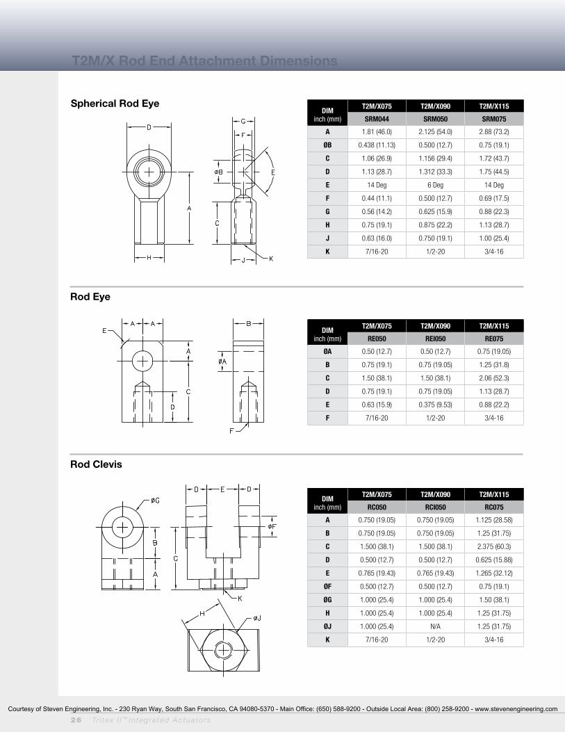
DIMinch (mm)
T2M/X075 T2M/X090 T2M/X115
SRM044 SRM050 SRM075
A 1.81 (46.0) 2.125 (54.0) 2.88 (73.2)
ØB 0.438 (11.13) 0.500 (12.7) 0.75 (19.1)
C 1.06 (26.9) 1.156 (29.4) 1.72 (43.7)
D 1.13 (28.7) 1.312 (33.3) 1.75 (44.5)
E 14 Deg 6 Deg 14 Deg
F 0.44 (11.1) 0.500 (12.7) 0.69 (17.5)
G 0.56 (14.2) 0.625 (15.9) 0.88 (22.3)
H 0.75 (19.1) 0.875 (22.2) 1.13 (28.7)
J 0.63 (16.0) 0.750 (19.1) 1.00 (25.4)
K 7/16-20 1/2-20 3/4-16
DIMinch (mm)
T2M/X075 T2M/X090 T2M/X115
RC050 RCI050 RC075
A 0.750 (19.05) 0.750 (19.05) 1.125 (28.58)
B 0.750 (19.05) 0.750 (19.05) 1.25 (31.75)
C 1.500 (38.1) 1.500 (38.1) 2.375 (60.3)
D 0.500 (12.7) 0.500 (12.7) 0.625 (15.88)
E 0.765 (19.43) 0.765 (19.43) 1.265 (32.12)
ØF 0.500 (12.7) 0.500 (12.7) 0.75 (19.1)
ØG 1.000 (25.4) 1.000 (25.4) 1.50 (38.1)
H 1.000 (25.4) 1.000 (25.4) 1.25 (31.75)
ØJ 1.000 (25.4) N/A 1.25 (31.75)
K 7/16-20 1/2-20 3/4-16
DIMinch (mm)
T2M/X075 T2M/X090 T2M/X115
RE050 REI050 RE075
ØA 0.50 (12.7) 0.50 (12.7) 0.75 (19.05)
B 0.75 (19.1) 0.75 (19.05) 1.25 (31.8)
C 1.50 (38.1) 1.50 (38.1) 2.06 (52.3)
D 0.75 (19.1) 0.75 (19.05) 1.13 (28.7)
E 0.63 (15.9) 0.375 (9.53) 0.88 (22.2)
F 7/16-20 1/2-20 3/4-16
T2M/X Rod End Attachment Dimensions
Spherical Rod Eye
Rod Eye
Rod Clevis
Courtesy of Steven Engineering, Inc. - 230 Ryan Way, South San Francisco, CA 94080-5370 - Main Office: (650) 588-9200 - Outside Local Area: (800) 258-9200 - www.stevenengineering.com
Tr i tex I I ™ In tegra ted Actua to rs 27
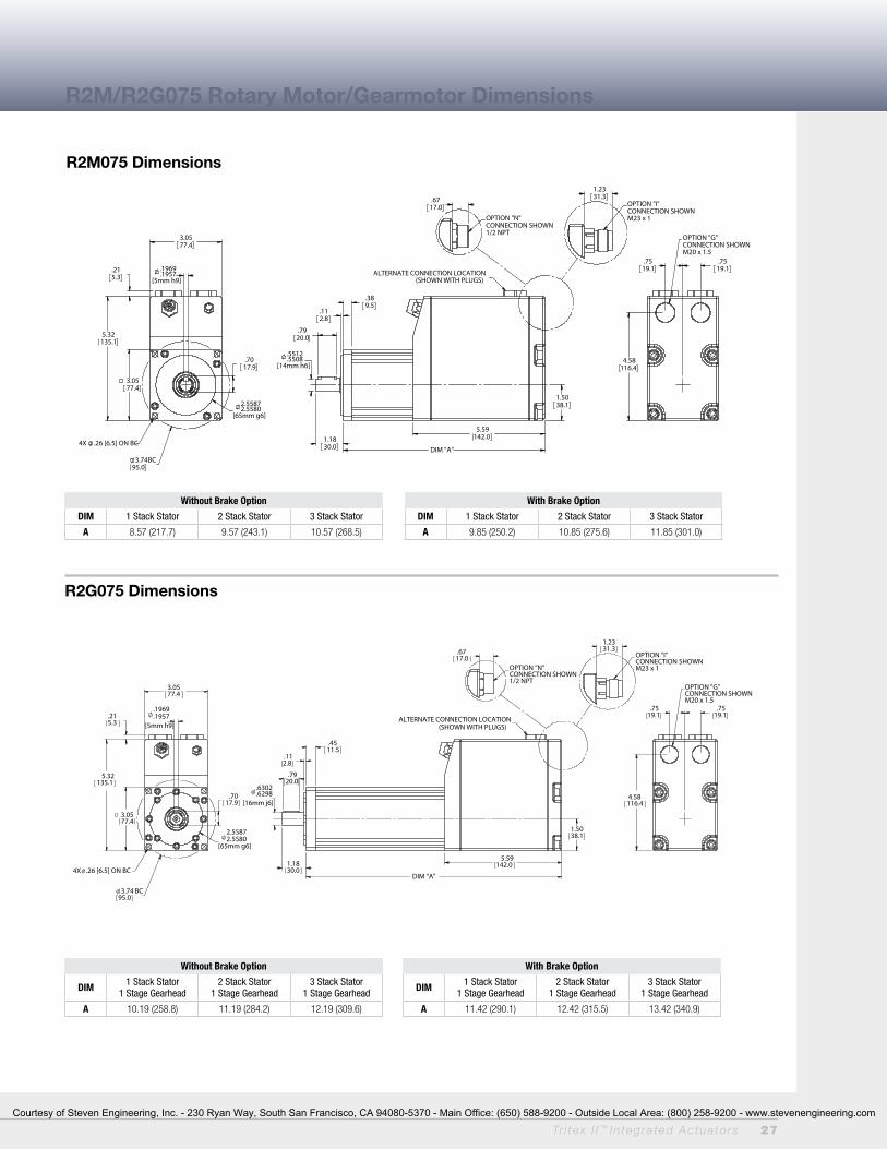
R2M075 Dimensions
R2G075 Dimensions
Without Brake Option
DIM 1 Stack Stator 2 Stack Stator 3 Stack Stator
A 8.57 (217.7) 9.57 (243.1) 10.57 (268.5)
Without Brake Option
DIM 1 Stack Stator1 Stage Gearhead
2 Stack Stator1 Stage Gearhead
3 Stack Stator1 Stage Gearhead
A 10.19 (258.8) 11.19 (284.2) 12.19 (309.6)
With Brake Option
DIM 1 Stack Stator1 Stage Gearhead
2 Stack Stator1 Stage Gearhead
3 Stack Stator1 Stage Gearhead
A 11.42 (290.1) 12.42 (315.5) 13.42 (340.9)
With Brake Option
DIM 1 Stack Stator 2 Stack Stator 3 Stack Stator
A 9.85 (250.2) 10.85 (275.6) 11.85 (301.0)
R2M/R2G075 Rotary Motor/Gearmotor Dimensions
3.0577.4
.1969
.1957[5mm h9]
3.7495.0
BC
2.55872.5580
[65mm g6]
3.0577.4
.7017.9
4X .26 [6.5] ON BC
5.32135.1
.215.3
1.5038.1
5.59142.0
DIM "A"
.5512
.5508[14mm h6]
1.1830.0
.112.8
.389.5
.7920.0
ALTERNATE CONNECTION LOCATION(SHOWN WITH PLUGS)
.7519.1
.7519.1
4.58116.4
OPTION "G"CONNECTION SHOWNM20 x 1.5
1.2331.3
OPTION "I"CONNECTION SHOWNM23 x 1
.6717.0
OPTION "N"CONNECTION SHOWN1/2 NPT
3.0577.4
.1969
.1957[5mm h9]
3.7495.0
BC
2.55872.5580
[65mm g6]
3.0577.4
.7017.9
4X .26 [6.5] ON BC
5.32135.1
.215.3
1.5038.1
DIM "A"
1.1830.0
.112.8
.6302
.6298[16mm j6]
5.59142.0
.7920.0
.4511.5
ALTERNATE CONNECTION LOCATION(SHOWN WITH PLUGS)
.7519.1
.7519.1
4.58116.4
OPTION "G"CONNECTION SHOWNM20 x 1.5
1.2331.3
OPTION "I"CONNECTION SHOWNM23 x 1
.6717.0
OPTION "N"CONNECTION SHOWN1/2 NPT
Courtesy of Steven Engineering, Inc. - 230 Ryan Way, South San Francisco, CA 94080-5370 - Main Office: (650) 588-9200 - Outside Local Area: (800) 258-9200 - www.stevenengineering.com
28 Tr i tex I I ™ In tegra ted Actua to rs
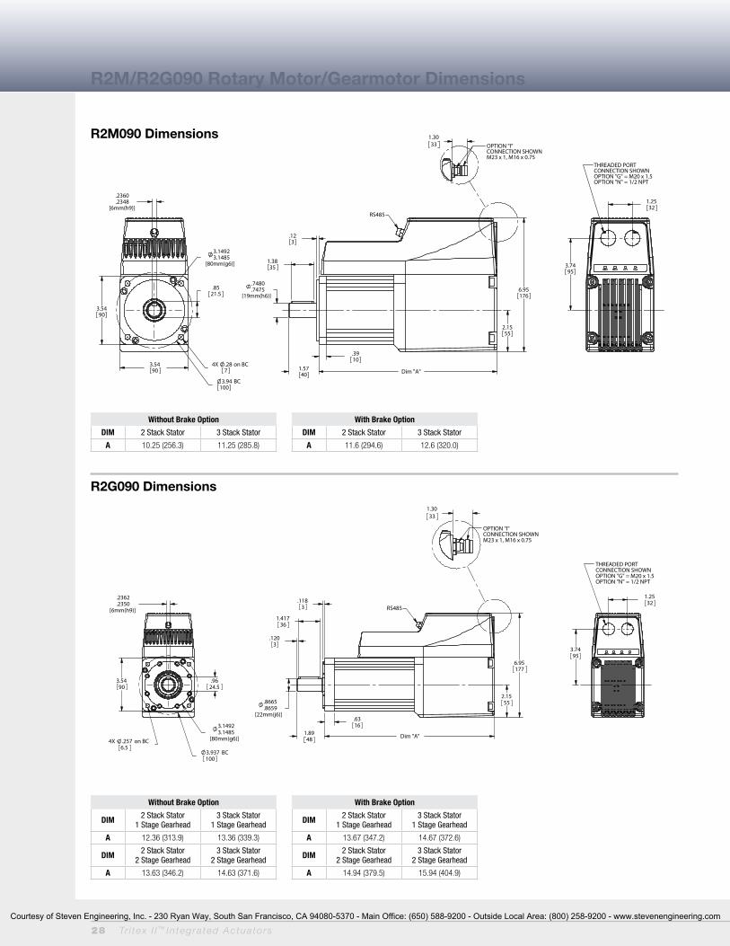
R2M/R2G090 Rotary Motor/Gearmotor Dimensions
R2M090 Dimensions
R2G090 Dimensions
Without Brake Option
DIM 2 Stack Stator 3 Stack Stator
A 10.25 (256.3) 11.25 (285.8)
Without Brake Option
DIM 2 Stack Stator1 Stage Gearhead
3 Stack Stator1 Stage Gearhead
A 12.36 (313.9) 13.36 (339.3)
DIM 2 Stack Stator2 Stage Gearhead
3 Stack Stator2 Stage Gearhead
A 13.63 (346.2) 14.63 (371.6)
With Brake Option
DIM 2 Stack Stator1 Stage Gearhead
3 Stack Stator1 Stage Gearhead
A 13.67 (347.2) 14.67 (372.6)
DIM 2 Stack Stator2 Stage Gearhead
3 Stack Stator2 Stage Gearhead
A 14.94 (379.5) 15.94 (404.9)
With Brake Option
DIM 2 Stack Stator 3 Stack Stator
A 11.6 (294.6) 12.6 (320.0)
3.5490
3.94 BC100
4X .28 on BC7
3.14923.1485
[80mm(g6)]
3.5490
.8521.5
.2360
.2348[6mm(h9)]
2.1555
1.5740 Dim "A"
.123
.7480
.7475[19mm(h6)]
6.95176
.3910
1.3835
RS485
1.2532
3.7495
THREADED PORT CONNECTION SHOWNOPTION "G" = M20 x 1.5OPTION "N" = 1/2 NPT
1.3033
OPTION "I"CONNECTION SHOWNM23 x 1, M16 x 0.75
3.5490
3.14923.1485
[80mm(g6)]
.9624.5
.2362
.2350[6mm(h9)]
3.937 BC100
4X .257 on BC6.5
Dim "A"1.8948
.1183
.8665
.8659[22mm(j6)]
1.41736
.1203
2.1555
6.95177
.6316
RS485
1.2532
3.7495
THREADED PORTCONNECTION SHOWNOPTION "G" = M20 x 1.5OPTION "N" = 1/2 NPT
1.3033
OPTION "I"CONNECTION SHOWNM23 x 1, M16 x 0.75
Courtesy of Steven Engineering, Inc. - 230 Ryan Way, South San Francisco, CA 94080-5370 - Main Office: (650) 588-9200 - Outside Local Area: (800) 258-9200 - www.stevenengineering.com

Tr i tex I I ™ In tegra ted Actua to rs 29
R2M115 Dimensions
R2G115 Dimensions
Without Brake Option
DIM 1 Stack Stator 2 Stack Stator
A 9.87 (250.7) 11.87 (301.5)
Without Brake Option
DIM 1 Stack Stator1 Stage Gearhead
2 Stack Stator1 Stage Gearhead
A 13.88 (352.6) 15.88 (403.4)
DIM 1 Stack Stator2 Stage Gearhead
2 Stack Stator2 Stage Gearhead
A 15.49 (393.4) 17.49 (444.2)
With Brake Option
DIM 1 Stack Stator1 Stage Gearhead
2 Stack Stator1 Stage Gearhead
A 15.43 (391.9) 17.43 (442.7)
DIM 1 Stack Stator2 Stage Gearhead
2 Stack Stator2 Stage Gearhead
A 17.04 (432.8) 19.04 (483.6)
With Brake Option
DIM 1 Stack Stator 2 Stack Stator
A 11.60 (294.6) 13.60 (345.4)
R2M/R2G115 Rotary Motor/Gearmotor Dimensions
4.53115
.3150
.3135[8mm(h9)] 4.3302
4.3294[110mm(g6)]
4X .34 on BC8.5
5.12 BC130
1.0627
4.53115
Dim "A"1.97
50
.9449
.9444[24mm(h6)]
1.4135.9
.164
.031
2.2758
7.56192
.4512
RS485
1.2532
4.23108
THREADED PORTCONNECTION SHOWNOPTION "G" = M20 x 1.5OPTION "N" = 1/2 NPT
1.3033
OPTION "I"CONNECTION SHOWNM23 x 1, M16 x 0.75
4.530115
.3937
.3923[10mm(h9)]
4X .34 on BC8.5
4.33024.3294
[110mm(g6)]
5.118 BC130
1.38035
1.26031.2596
[32mm (j6)]
2.5565
Dim "A"
7.56192
2.2758
.205.1
1.5840
.6416
.1574
RS485
1.2532
4.23108
THREADED PORTCONNECTION SHOWNOPTION "G" = M20 x 1.5OPTION "N" = 1/2 NPT
1.3033
OPTION "I"CONNECTION SHOWNM23 x 1, M16 x 0.75
Courtesy of Steven Engineering, Inc. - 230 Ryan Way, South San Francisco, CA 94080-5370 - Main Office: (650) 588-9200 - Outside Local Area: (800) 258-9200 - www.stevenengineering.com

30 Tr i tex I I ™ In tegra ted Actua to rs
NOTES:1. Requires customer supplied Ethernet
cable through I/O port for Class 1 Div 2 compliance only.
2. To achieve -40˚ C operating temperature, specify -XL in the actuator model mask and define Mobilgrease 28 in order notes. Other special lubricants are also available.
Linear Actuator Ordering Guide
Rotary Motor and Gearmotor Ordering Guide
T2M/X = Actuator TypeT2M = Tritex II Linear Actuator, standard
mechanical capacityT2X = Tritex II Linear Actuator, high
mechanical capacity
BBB = Actuator Frame Size075 = 75 mm 090 = 90 mm115 = 115 mm
CC = Stroke Length03 = 3 inch (76 mm) (N/A T2M/X115)04 = 4 inch (102 mm) (T2M/X115 only)06 = 6 inch (150 mm)10 = 10 inch (254 mm)12 = 12 inch (305 mm)14 = 14 inch (356 mm) (T2M/X075)18 = 18 inch (457 mm)
DD = Lead (linear travel per screw revolution)
01 = 0.1 inch (2.54 mm)02 = 0.2 inch (5.08 mm)05 = 0.5 inch (12.7 mm)08 = 0.75 inch (19.05 mm)
(T2M/X115 only)5
E = ConnectionsG = Standard Straight Threaded Port with
Internal terminals, M20 x 1.5N = NPT Threaded Port via Adapter with
Internal Terminals, 1/2" NPTI = Intercontec Style - Exlar std, M16/M23
Style ConnectorB = Embedded leads 3' std J = Embedded leads w/ “I” plug 3' stdX = Custom Connectivity
F = MountingB = Front & Rear FlangeC = Rear ClevisD = Double Side MountE = Extended Tie Rod
F = Front FlangeG = Metric Rear ClevisJ = Metric Side MountK = Metric Double Side MountM = Metric Extended Tie RodQ = Metric Side TrunnionR = Rear FlangeS = Side MountT = Side TrunnionX = Special
G = Rod End A = Male Metric Thread1
B = Female Metric Thread1
F = Female US Standard Thread1
L = Female Metric Thread SS1,2
M = Male US Standard Thread1 R = Male Metric Thread SS1,2
V = Female US Standard Thread SS1,2
W = Male, US Standard Thread SS1,2
X = Special (please specify)
HH = Feedback TypeHD = Analog Hall DeviceIE = Incremental Encoder, 8192 count
resolutionAF = Absolute Feedback
III-II = Motor Stator, All 8 Pole T2M/X075 Stator Specifications138-40 = 1 Stack, 230 VAC, 4000 rpm238-30 = 2 Stack, 230 VAC, 3000 rpm338-20 = 3 Stack, 230 VAC, 2000 rpm
T2M/X090 Stator Specifications138-40 = 1 Stack, 230 VAC, 4000 rpm238-40 = 2 Stack, 230 VAC, 4000 rpm238-30 = 2 Stack, 230 VAC. 3000 rpm9
T2M/X115 Stator Specifications138-30 = 1 Stack, 230 VAC, 3000 rpm238-20 = 2 Stack, 230 VAC, 2000 rpm238-15 = 2 Stack, 230 VAC, 1500 rpm9
(N/A with 0.1" lead)
JJJ = Voltage230 = 115-230 VAC, single phase
KKK = Option Board (only 1 selection allowed)
SIO = Standard I/O InterconnectIA4 = 4-20 mA Analog I/OCOP = CANOpen w/M12 connector CON = CANOpen, without M1210
EIP = SIO plus Ethernet/IP w/M12 connectorEIN = SIO plus Ethernet/IP without M12
connector10
PIO = SIO plus Profinet IO w/M12 connectorPIN = SIO plus Profinet IO without M12
connector10
TCP = SIO plus Modbus TCP w/M12 connector
TCN = SIO plus Modbus TCP without M12 connector10
X..XX = Travel and Housing Options (Multiples Possible)
Travel OptionsAR = External Anti-rotatePF = Preloaded Follower3
L1/2/3 = External Limit Switches7
HW = Manual Drive, Handwheel with Interlock Switch (T2X only)
SD = Manual Drive, Side HexRB = Rear BrakePB = Protective Bellows (N/A with extended
tie rod mounting option)SR = Splined Main Rod8,2
XT = Special Travel OptionsHousing OptionsP5 = IP65 Sealed Housing (T2M only)HC = Type III Hard Coat Anodized4
FG = White Epoxy Coating4
XH = Special Housing Option.
Special Motor OptionsXL = Special Lubrication6
XM = Special Motor Option
##### = Part No Designator for SpecialsOptional 5 digit assigned PN to designate unique model numbers
R2M/G = Motor TypeR2M = Tritex II AC Rotary MotorR2G = Tritex II AC Rotary GearmotorAAA = Frame Size075 = 75 mm090 = 90 mm115 = 115 mmBBB = Gear RatioBlank = R2MSingle Reduction Ratios004 = 4:1005 = 5:1010 = 10:1Double Reduction Ratios (N/A on 75mm)016 = 16:1 020 = 20:1025 = 25:1 040 = 40:1050 = 50:1 100 = 100:1C = Shaft TypeK = KeyedR = Smooth/RoundX = Special Shaft
D = ConnectionsG = Standard Straight Threaded Port with
Internal Terminals, M20 x 1.5N = NPT Threaded Port with Internal
Terminals, 1/2" NPTI = Intercontec style - Exlar Standard,
M16/M23 Style ConnectorB = Embedded leads 3' std J = Embedded leads w/ “I” plug 3' std X = Custom ConnectivityE = Coating OptionsG = Exlar StandardH = Type III Hard Coat AnodizedF = Smooth White Epoxy CoatingX = Special or CustomF = Brake OptionS = No Brake, StandardB = Electric Brake, 24 VDCGG = Feedback TypeHD = Analog Hall DeviceIE = Incremental Encoder, 8192 Count
ResolutionAF = Absolute Feedback
HHH-HH = Motor StatorsR2M/G075 Stator Specifications138-40 = 1 Stack, 230 VAC, 4000 rpm238-30 = 2 Stack, 230 VAC, 3000 rpm338-20 = 3 Stack, 230 VAC, 2000 rpmR2M/G090 Stator Specifications238-40 = 2 Stack, 230 VAC, 4000 rpm238-30 = 2 Stack, 230 VAC, 3000 rpm338-20 = 3 Stack, 230 VAC, 2000 rpmR2M/G115 Stator Specifications138-30 = 1 Stack, 230 VAC, 3000 rpm238-20 = 2 Stack, 230 VAC, 2000 rpm238-15 = 2 Stack, 230 VAC, 1500 rpmIII = Voltage230 = 115-230 VAC, Single PhaseJJJ = Option BoardSIO = Standard I/O InterconnectIA4 = 4-20 mA Analog I/OCOP = CANOpen w/M12 connector CON = CANOpen, without M12 connector1
EIP = SIO plus Ethernet/IP w/M12 connectorEIN = SIO plus Ethernet/IP without M12
connector1
PIO = SIO plus Profinet IO w/M12 connector
PIN = SIO plus Profinet IO without M12 connector1
TCP = SIO plus Modbus TCP w/M12 connectorTCN = SIO plus Modbus TCP without M12
connector1
XX = Special Options (multiples possible)HW = Manual Drive, Handwheel with
Interlock SwitchSD = Manual Drive, Side HexXH = Special Housing OptionsXM = Special Motor OptionsXL = Special Lubrication2
##### = Part No Designator for SpecialsOptional 5 digit assigned PN to designate unique model no.
NOTES:
1. Chrome-plated carbon steel. Threads not chrome-plated.
2. Consult Exlar when ordering splined stainless steel main rod.
3. The dynamic load rating of zero backlash, preloaded screws is 63% of the dynamic load rating of the std non-preloaded screws. The calculated travel life of a preloaded screw will be 25% of the calculated travel life of the same size and lead of a non-preloaded screw.
4. This housing option may indicate the need for special material main rods or mounting.
5. 0.75 lead not available above 12" stroke.
6. To achieve -40 operating temperature, specify -XL in the actuator model mask and define Mobilgrease 28 in order notes. Other special lubricants are also available.
7. Limit switch option requires AR option.
8. This option is not sealed and is not suitable for any environment in which contaminants come in contact with actuator and may enter the actuator.
9. N/A with 0.1" lead
10. Requires customer supplied Ethernet cable through I/O port for Class 1 Div 2 compliance only.
Tritex II AC T2M/X Linear Actuator Ordering Information
Tritex II AC R2M Motor or R2G Gearmotor Ordering Information
T2M/XBBB-CCDD-EFG-HH-III-II-JJJ-KKK- (XX..XX - #####)
R2M/GAAA-BBB-CDEF-GG-HHH-HH-III-JJJ (XX...XX) - #####)
Courtesy of Steven Engineering, Inc. - 230 Ryan Way, South San Francisco, CA 94080-5370 - Main Office: (650) 588-9200 - Outside Local Area: (800) 258-9200 - www.stevenengineering.com
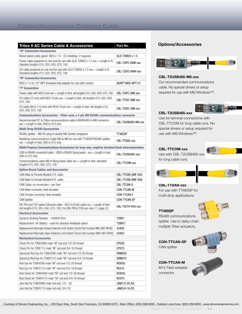
Tr i tex I I ™ In tegra ted Actua to rs 31
Tritex II AC Series Cable & Accessories Part No.
“G” Connection Accessories
Nickel plated cable gland- M20 x 1.5 - CE shielding- 2 required GLD-T2M20 x 1.5
Power cable prepared on one end for use with GLD-T2M20 x 1.5 xxx = Length in ft, Standard lengths 015, 025, 050, 075, 100 CBL-T2IPC-RAW-xxx
I/O cable prepared on one end for use with GLD-T2M20 x 1.5 xxx = Length in ft, Standard lengths 015, 025, 050, 075, 100 CBL-T2IOC-RAW-xxx
“N” Connection Accessories
M20 x 1.5 to 1/2" NPT threaded hole adapter for use with conduit ADAPT-M20-NPT1/2
“I” Connection
Power cable with M23 6 pin xxx = Length in feet, std lengths 015, 025, 050, 075, 100 CBL-T2IPC-SMI-xxx
I/O cable (75 mm) with M23 19 pin xxx = Length in feet, std lengths 015, 025, 050, 075, 100 CBL-TTIOC-SMI-xxx
I/O cable (90 & 115 mm) with M16 19 pin xxx = Length in feet, std lengths 015, 025, 050, 075, 100 CBL-T2IOC-SMI-xxx
Communications Accessories - Tritex uses a 4 pin M8 RS485 communications connector
Recommended PC to Tritex communications cable-USB/RS485 to M8 connector - xxx = Length in feet, 006 or 015 only CBL-T2USB485-M8-xxx
Multi-Drop RS485 Accessories
RS485 splitter - M8 Pin plug to double M8 Socket receptacle TT485SP
Multidrop Communications Cable M8 to M8 for use with TT485SP/RS485 splitter - xxx = Length in feet, 006 or 015 only CBL-TTDAS-xxx
Multi-Purpose Communications Accessories for long runs, requires terminal block interconnections
USB to RS485 convertor/cable - USB to RS485 flying leads - xxx = Length in feet, 006 or 015 only CBL-T2USB485-xxx
Communications cable M8 to flying leads cable xxx = Length in feet, standard lengths 015, 025, 050, 075, 100 CBL-TTCOM-xxx
Option Board Cables and Accessories
CAN Male to Female Molded 3 ft. cable CBL-TTCAN-SMF-003
CAN Male to Female Molded 6 ft. cable CBL-TTCAN-SMF-006
CAN Cable, no connectors – per foot CBL-TTCAN-S
CAN Male connector, field wireable CON-TTCAN-M
CAN Female connector, field wireable CON-TTCAN-F
CAN Splitter CON-TTCAN-SP
EIP, PIO and TCP option Ethernet cable - M12 to RJ45 cable xxx = Length in feet, std lengths 015, 025, 050, 075, 100. For EIN, PIN & TCN see note 11, page 22. CBL-T2ETH-R45-xxx
Electrical Accessories
Dynamic Braking Resistor - 100W47Ohm T2BR1
Replacement -AF Battery - used for absolute feedback option T2BAT1
Replacement Normally Closed External Limit Switch (Turck Part number BIM-UNT-RP6X) 43404
Replacement Normally Open External Limit Switch (Turck Part number BIM-UNT-AP6X) 43403
Mechanical Accessories
Clevis Pin for T2M/X090 male “M” rod end 1/2-20 thread CP050
Clevis Pin for T2M/115 male “M” rod end 3/4-16 thread CP075
Spherical Rod Eye for T2M/X090 male “M” rod end 1/2-20 thread SRM050
Spherical Rod Eye for T2M/X115 male “M” rod end 3/4-16 thread SRM075
Rod Eye for T2M/X090 male “M” rod end 1/2-20 thread REI050
Rod Eye for T2M/X115 male “M” rod end 3/4-16 thread RE075
Rod Clevis for T2M/X090 male “M” rod end 1/2-20 thread RCI050
Rod Clevis for T2M/X115 male “M” rod end 3/4-16 thread RC075
Jam Nut for T2M/X090 male rod end, 1/2 - 20 JAM1/2-20-SS
Jam Nut for T2M/X115 male rod end, 3/4-16 JAM3/4-16-SS
Cables/Accessories Ordering Guide
Options/Accessories
CBL-T2USB485-M8-xxxOur recommended communications cable. No special drivers or setup required for use with MS Windows™.
CBL-T2USB485-xxxUse for terminal connections with CBL-TTCOM for long cable runs. No special drivers or setup required for use with MS Windows™.
CBL-TTCOM-xxxUse with CBL-T2USB485-xxx for long cable runs.
CBL-TTDAS-xxxFor use with TT485SP for multi-drop applications.
TT485SPRS485 communicationssplitter. Use to daisy-chain multiple Tritex actuators.
CON-TTCAN-SPCAN splitter
CON-TTCAN-MM12 Field wireable connector
Courtesy of Steven Engineering, Inc. - 230 Ryan Way, South San Francisco, CA 94080-5370 - Main Office: (650) 588-9200 - Outside Local Area: (800) 258-9200 - www.stevenengineering.com

32 Tr i tex I I ™ In tegra ted Actua to rs
No Compromises on Power, Performance or ReliabilityWith forces to approximately 950 lbs (4kN) continuous and 1,300 lbf peak (6 kN), and speeds to 33 in/sec (800 mm/sec), the DC Tritex II linear actuators also offer a benefit that no other integrated product offers– POWER! No longer are you limited to trivial amounts of force, or speeds so slow that many motion applications are not possible. And the new Tritex II with DC power electronics operates with maximum reliability over a broad range of ambient temperatures: -40˚C to +65˚C. The DC powered Tritex II actuators contain a 750 W servo amplifier and a very capable motion controller. With standard features such as analog following for position, compound moves, move chaining and individual force/torque control for each move, the Tritex II Series is the ideal solution for most motion applications.
Tritex II Linear DC Actuator
Tritex II Models
• TDM standard mechanical capacity actuator, 60 and 75 mm
• TDX high mechanical capacity actuator, 60 and 75 mm
• RDM rotary motor, 60, 75 and 90 mm
• RDG rotary gearmotor, 60, 75 and 90 mm
Power Requirements
• DC Power 12-48 VDC nominal• Connections for external braking
resistor
Feedback Types• Analog Hall with 1000 count
resolution• Incremental encoder with 8192
count resolution• Absolute Feedback (analog hall
with multi-turn, battery backup)
Connectivity
• Internal terminals accessible through removable cover (75 and 90 mm only)
• Threaded ports for cable glands (75 and 90 mm only)
• Optional connectors - M23 Power - M23 I/O
• M8 connector for RS485• M12 connector for EtherNet options• Custom connection options• Embedded leads
163694
Tritex II DC Linear & Rotary Actuators
Tritex II rotary motor with connectors shown left and Tritex II linear actuator with customer-supplied cable glands ports shown above.
Courtesy of Steven Engineering, Inc. - 230 Ryan Way, South San Francisco, CA 94080-5370 - Main Office: (650) 588-9200 - Outside Local Area: (800) 258-9200 - www.stevenengineering.com
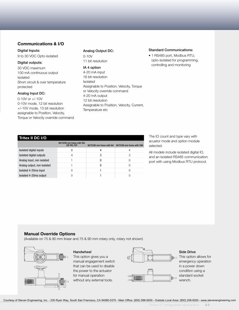
Tr i tex I I ™ In tegra ted Actua to rs 33
Manual Override Options (Available on 75 & 90 mm linear and 75 & 90 mm rotary only, rotary not shown)
Handwheel This option gives you a manual engagement switch that can be used to disable the power to the actuator for manual operation without any external tools.
Side Drive This option allows for emergency operation in a power down condition using a standard socket wrench.
Communications & I/O
Digital Inputs:
9 to 30 VDC Opto-isolated
Digital outputs:
30 VDC maximum 100 mA continuous output IsolatedShort circuit & over temperature protected
Analog Input DC:
0-10V or +/-10V0-10V mode, 12 bit resolution +/-10V mode, 13 bit resolution assignable to Position, Velocity, Torque or Velocity override command
Analog output DC:
0-10V11 bit resolution
IA 4 option 4-20 mA input16 bit resolutionIsolatedAssignable to Position, Velocity, Torque or Velocity override command4-20 mA output12 bit resolutionAssignable to Position, Velocity, Current, Temperature etc
Standard Communications:
• 1 RS485 port, Modbus RTU, opto-isolated for programming, controlling and monitoring
The IO count and type vary with acuator mode and option module selected.
All models include isolated digital IO, and an isolated RS485 communication port with using Modbus RTU protocol.
Tritex II DC I/O60/75/90 mm frame with SIO,
EIP, PIO, TCP 60/75/90 mm frame with IA4 60/75/90 mm frame with CAN
Isolated digital inputs 8 4 4
Isolated digital outputs 4 3 3
Analog input, non isolated 1 0 0
Analog output, non isolated 1 0 0
Isolated 4-20ma input 0 1 0
Isolated 4-20ma output 0 1 0
Courtesy of Steven Engineering, Inc. - 230 Ryan Way, South San Francisco, CA 94080-5370 - Main Office: (650) 588-9200 - Outside Local Area: (800) 258-9200 - www.stevenengineering.com
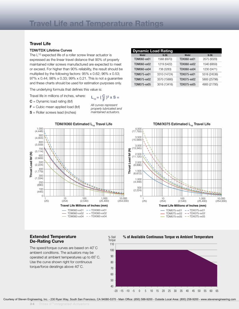
34 Tr i tex I I ™ In tegra ted Actua to rs
Travel LifeTDM/TDX Lifetime CurvesThe L10 expected life of a roller screw linear actuator is expressed as the linear travel distance that 90% of properly maintained roller screws manufactured are expected to meet or exceed. For higher than 90% reliability, the result should be multiplied by the following factors: 95% x 0.62; 96% x 0.53; 97% x 0.44; 98% x 0.33; 99% x 0.21. This is not a guarantee and these charts should be used for estimation purposes only.
The underlying formula that defines this value is:
Travel life in millions of inches, where:
C = Dynamic load rating (lbf)
F = Cubic mean applied load (lbf)
S = Roller screws lead (inches)
Extended TemperatureDe-Rating CurveThe speed/torque curves are based on 40˚ C ambient conditions. The actuators may be operated at ambient temperatures up to 65˚ C. Use the curve shown right for continuous torque/force deratings above 40˚ C.
All curves represent properly lubricated and maintained actuators.
L10 = ( C )3 x S = F
Ambient Temperature, Deg C
% Stall Torque 110
100
90
80
70
60
50
40 -20 -15 -10 -5 0 5 10 15 20 25 30 35 40 45 50 55 60 65
% of Available Continuous Torque vs Ambient Temperature
Travel Life and Temperature Ratings
Dynamic Load RatingModel lb (N) Model lb (N)
TDM060-xx01 1568 (6970) TDX060-xx01 2075 (9320)
TDM060-xx02 1219 (5422) TDX060-xx02 1540 (6850)
TDM060-xx04 738 (3283) TDX060-xx04 1230 (5471)
TDM075-xx01 3310 (14724) TDX075-xx01 5516 (24536)
TDM075-xx02 3570 (15880) TDX075-xx02 5800 (25798)
TDM075-xx05 3016 (13416) TDX075-xx05 4900 (21795)
TDM/X075 Estimated L10 Travel Life
TDM/X060 Estimated L10 Travel Life
TDM060-xx01TDM060-xx02TDM060-xx04
1,000(4,448)
900(4,003)
800(3,559)
700(3,114)
600(2,669)
500(2,224)
400(1,779)
300(1,334)
200(890)
100(445)
0
Th
rust
Lo
ad lb
f (N
)T
hru
st L
oad
lbf
(N)
Travel Life Millions of Inches (mm)
Travel Life Millions of Inches (mm)
TDX060-xx01TDX060-xx02TDX060-xx04
TDM075-xx01TDM075-xx02TDM075-xx05
4,000(17,793)
3,500(15,569)
3,000(13,345)
2,500(11,120)
2,000(8,896)
1,500(6,672)
1,000(4,448)
500(2,224)
0 1 10 100 1,000 10,000 (25) (254) (2,540) (25,400) (254,000)
TDX075-xx01TDX075-xx02TDX075-xx05
1 10 100 1,000 10,000 (25) (254) (2,540) (25,400) (254,000)
TDM/X060 Estimated L10 Travel Life TDM/X075 Estimated L10 Travel LifeTDM/X075 Estimated L10 Travel Life
TDM/X060 Estimated L10 Travel Life
TDM060-xx01TDM060-xx02TDM060-xx04
1,000(4,448)
900(4,003)
800(3,559)
700(3,114)
600(2,669)
500(2,224)
400(1,779)
300(1,334)
200(890)
100(445)
0
Th
rust
Lo
ad lb
f (N
)T
hru
st L
oad
lbf
(N)
Travel Life Millions of Inches (mm)
Travel Life Millions of Inches (mm)
TDX060-xx01TDX060-xx02TDX060-xx04
TDM075-xx01TDM075-xx02TDM075-xx05
4,000(17,793)
3,500(15,569)
3,000(13,345)
2,500(11,120)
2,000(8,896)
1,500(6,672)
1,000(4,448)
500(2,224)
0 1 10 100 1,000 10,000 (25) (254) (2,540) (25,400) (254,000)
TDX075-xx01TDX075-xx02TDX075-xx05
1 10 100 1,000 10,000 (25) (254) (2,540) (25,400) (254,000)
Courtesy of Steven Engineering, Inc. - 230 Ryan Way, South San Francisco, CA 94080-5370 - Main Office: (650) 588-9200 - Outside Local Area: (800) 258-9200 - www.stevenengineering.com

Tr i tex I I ™ In tegra ted Actua to rs 35
TDM/X060 Linear Actuator Speed vs. Force Curves
Speed inch/sec (mm/sec)
TDM/X060 1B8-50* Peak
ContinuousFo
rce
lbf (
N)
LEAD inch (mm) 0.4 0.2 0.1 (10.16) (5.08) (2.54)
0 1.67 (42.2) 3.33 (84.6) 5 (127) 6.67 (169.4) 8.33 (211.6) 0 3.33 (84.6) 6.67 (169.4) 10 (254) 13.33 (388.6) 16.67 (423.4) 0 6.67 (169.4) 13.33 (388.6) 20 (508) 26.67 (677.4) 33.33 (846.6)
*Using NEMA recommended aluminum heatsink 10 x 10 x 1/4 inch
LEAD inch (mm)0.1 (2.54)0.2 (5.08)0.4 (10.16)
24 VDC
200(890)175
(780)150
(667)100
(449)75
(334)50
(222)25
(111)0
375(1668)
325(1446)
250(1112)
200(890)150
(667)100
(445)50
(222)0
700(3114)
600(2669)
500(2224)
400(1779)
300(1334)
200(890)100
(449)0
Speed inch/sec (mm/sec)
TDM/X060 2B8-50* Peak
Continuous
Forc
e lb
f (N)
LEAD inch (mm) 0.4 0.2 0.1 (10.16) (5.08) (2.54)
0 1.67 (42.2) 3.33 (84.6) 5 (127) 6.67 (169.4) 8.33 (211.6) 0 3.33 (84.6) 6.67 (169.4) 10 (254) 13.33 (388.6) 16.67 (423.4) 0 6.67 (169.4) 13.33 (388.6) 20 (508) 26.67 (677.4) 33.33 (846.6)
*Using NEMA recommended aluminum heatsink 10 x 10 x 1/4 inch
LEAD inch (mm)0.1 (2.54)0.2 (5.08)0.4 (10.16)
24 VDC
200(890)175
(780)150
(667)100
(449)75
(334)50
(222)25
(111)0
375(1668)
325(1446)
250(1112)
200(890)150
(667)100
(445)50
(222)0
700(3114)
600(2669)
500(2224)
400(1779)
300(1334)
200(890)100
(449)0
Speed inch/sec (mm/sec)
TDM/X060 3B8-40* Peak
Continuous
Forc
e lb
f (N)
LEAD inch (mm) 0.4 0.2 (10.16) (5.08)
0 3.33 (84.6) 6.67 (169.4) 10 (254) 13.33 (338.6) 0 6.67 (169.4) 13.33 (388.6) 20 (508) 26.67 (677.4)
*Using NEMA recommended aluminum heatsink 10 x 10 x 1/4 inch
LEAD inch (mm)0.2 (5.08)0.4 (10.16)
24 VDC
250(1112)
225(1000)
200(890)175
(780)150
(667)100
(449)75
(334)50
(222)25
(111)0
475(2113)
425(1890)
375(1668)
325(1446)
250(1112)
200(890)150
(667)100
(445)50
(222)0
Courtesy of Steven Engineering, Inc. - 230 Ryan Way, South San Francisco, CA 94080-5370 - Main Office: (650) 588-9200 - Outside Local Area: (800) 258-9200 - www.stevenengineering.com
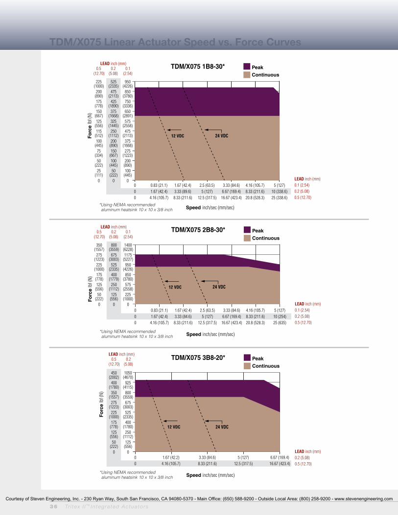
36 Tr i tex I I ™ In tegra ted Actua to rs
TDM/X075 Linear Actuator Speed vs. Force Curves
Speed inch/sec (mm/sec)
TDM/X075 1B8-30* Peak
Continuous
Forc
e lb
f (N)
LEAD inch (mm) 0.5 0.2 0.1 (12.70) (5.08) (2.54)
0 0.83 (21.1) 1.67 (42.4) 2.5 (63.5) 3.33 (84.6) 4.16 (105.7) 5 (127) 0 1.67 (42.4) 3.33 (89.6) 5 (127) 6.67 (169.4) 8.33 (211.6) 10 (338.6) 0 4.16 (105.7) 8.33 (211.6) 12.5 (317.5) 16.67 (423.4) 20.8 (528.3) 25 (338.6)
*Using NEMA recommended aluminum heatsink 10 x 10 x 3/8 inch
LEAD inch (mm)0.1 (2.54)0.2 (5.08)0.5 (12.70)
24 VDC
525(2335)
475(2113)
425(1890)
375(1668)
325(1445)
250(1112)
200(890)150
(667)100
(445)50
(222)0
225(1000)
200(890)175
(778)150
(667)125
(556)115
(512)100
(445)75
(334)50
(222)25
(111)0
950(4226)
850(3780)
750(3336)
650(2891)
575(2558)
475(2113)
375(1668)
275(1223)
200(890)100
(445)0
12 VDC
Speed inch/sec (mm/sec)
TDM/X075 2B8-30* Peak
Continuous
Forc
e lb
f (N)
LEAD inch (mm) 0.5 0.2 0.1 (12.70) (5.08) (2.54)
0 0.83 (21.1) 1.67 (42.4) 2.5 (63.5) 3.33 (84.6) 4.16 (105.7) 5 (127) 0 1.67 (42.4) 3.33 (84.6) 5 (127) 6.67 (169.4) 8.33 (211.6) 10 (254) 0 4.16 (105.7) 8.33 (211.6) 12.5 (317.5) 16.67 (423.4) 20.8 (528.3) 25 (635)
*Using NEMA recommended aluminum heatsink 10 x 10 x 3/8 inch
LEAD inch (mm)0.1 (2.54)0.2 (5.08)0.5 (12.70)
24 VDC
800(3559)
675(3003)
525(2335)
400(1779)
250(1112)
125(556)
0
350(1557)
275(1223)
225(1000)
175(778)125
(556)50
(222)0
1400(6228)1175
(5227)950
(4226)850
(3780)575
(2558)225
(1000)0
12 VDC
Speed inch/sec (mm/sec)
TDM/X075 3B8-20* Peak
Continuous
Forc
e lb
f (N)
LEAD inch (mm) 0.5 0.2 (12.70) (5.08)
0 1.67 (42.2) 3.33 (84.6) 5 (127) 6.67 (169.4) 0 4.16 (105.7) 8.33 (211.6) 12.5 (317.5) 16.67 (423.4)
*Using NEMA recommended aluminum heatsink 10 x 10 x 3/8 inch
LEAD inch (mm)0.2 (5.08)0.5 (12.70)
24 VDC
450(2002)
400(1780)
350(1557)
275(1223)
225(1000)
175(778)125
(556)50
(222)0
1050(4670)
925(4115)
800(3559)
675(3003)
525(2335)
400(1780)
250(1112)
125(556)
0
12 VDC
Courtesy of Steven Engineering, Inc. - 230 Ryan Way, South San Francisco, CA 94080-5370 - Main Office: (650) 588-9200 - Outside Local Area: (800) 258-9200 - www.stevenengineering.com
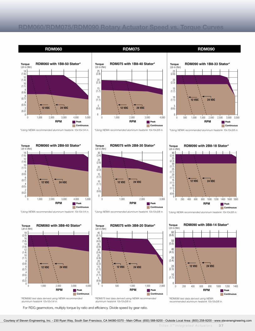
Tr i tex I I ™ In tegra ted Actua to rs 37
RDM060/RDM075/RDM090 Rotary Actuator Speed vs. Torque Curves
0 500 1,000 1,500 2,000 2,500 3,000 3,500RPM
TorqueLbf-in (Nm)
RDM090 with 1B8-33 Stator*
Peak
Continuous
*Using NEMA recommended aluminum heatsink 10x10x3/8 in.
25(2.8)
20(2.3)
15(1.7)
10(1.1)
5(0.6)
0
24 VDC12 VDC
0 200 400 600 800 1000 1200 1400RPM
TorqueLbf-in (Nm)
RDM090 with 3B8-14 Stator*
Peak
Continuous
*RDM090 test data derived using NEMA recommended aluminum heatsink 10x10x3/8 in.
60(6.8)
50(5.6)
40(4.5)
30(3.4)
20(2.3)
10(1.1)
0
24 VDC12 VDC
For RDG gearmotors, multiply torque by ratio and efficiency. Divide speed by gear ratio.
0 1,000 2,000 3,000 4,000 5,000RPM
TorqueLbf-in (Nm)
RDM060 with 2B8-50 Stator*
Peak
Continuous
*Using NEMA recommended aluminum heatsink 10x10x1/4 in.
14(1.6)
12(1.4)
10(1.1)
8(0.9)
6(0.7)
4(0.5)
2(0.2)
0
24 VDC12 VDC
0 1,000 2,000 3,000RPM
TorqueLbf-in (Nm)
RDM075 with 2B8-30 Stator*
Peak
Continuous
*Using NEMA recommended aluminum heatsink 10x10x3/8 in.
30(3.4)
25(2.8)
20(2.3)
15(1.7)
10(1.1)
5(0.6)
0
24 VDC12 VDC
RPM
TorqueLbf-in (Nm)
RDM090 with 2B8-18 Stator*
Peak
Continuous
*Using NEMA recommended aluminum heatsink 10x10x3/8 in.
0 200 400 600 800 1000 1200 1400 1600 1800
40(2.8)
35(2.3)
30(1.7)
25(1.1)
20(1.1)
15(1.1)
10(1.1)
5(0.6)
0
24 VDC12 VDC
RDM060 RDM075 RDM090
0 1,000 2,000 3,000 4,000RPM
TorqueLbf-in (Nm)
RDM060 with 3B8-40 Stator*
Peak
Continuous
*RDM060 test data derived using NEMA recommended aluminum heatsink 10x10x1/4 in.
18(2.0)
16(1.8)
14(1.6)
12(1.4)
10(1.1)
8(0.9)
6(0.7)
4(0.5)
2(0.2)
0
24 VDC12 VDC
0 500 1,000 1,500 2,000RPM
TorqueLbf-in (Nm)
RDM075 with 3B8-20 Stator*
Peak
Continuous
*RDM075 test data derived using NEMA recommended aluminum heatsink 10x10x3/8 in.
45(5.1)40
(4.5)35
(3.9)30
(3.4)25
(2.8)20
(2.3)15
(1.7)10
(1.1)5
(0.6)0
24 VDC12 VDC
0 1,000 2,000 3,000 4,000 5,000RPM
TorqueLbf-in (Nm)
RDM060 with 1B8-50 Stator*
Peak
Continuous
*Using NEMA recommended aluminum heatsink 10x10x1/4 in.
24 VDC
14(1.6)
12(1.4)
10(1.1)
8(0.9)
6(0.7)
4(0.5)
2(0.2)
0
12 VDC
0 1,000 2,000 3,000 4,000RPM
TorqueLbf-in (Nm)
RDM075 with 1B8-40 Stator*
Peak
Continuous
*Using NEMA recommended aluminum heatsink 10x10x3/8 in.
24 VDC
25(2.8)
20(2.3)
15(1.7)
10(1.1)
5(0.6)
0
12 VDC
Courtesy of Steven Engineering, Inc. - 230 Ryan Way, South San Francisco, CA 94080-5370 - Main Office: (650) 588-9200 - Outside Local Area: (800) 258-9200 - www.stevenengineering.com
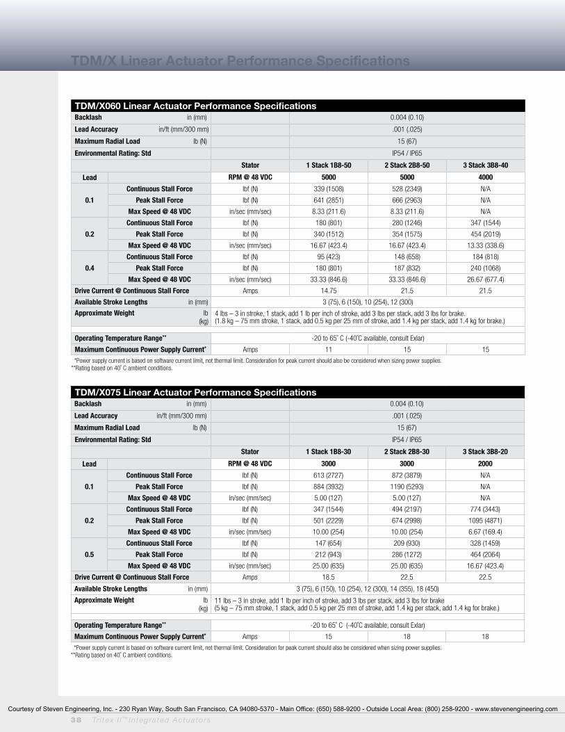
38 Tr i tex I I ™ In tegra ted Actua to rs
TDM/X Linear Actuator Performance Specifications
TDM/X060 Linear Actuator Performance SpecificationsBacklash in (mm) 0.004 (0.10)
Lead Accuracy in/ft (mm/300 mm) .001 (.025)
Maximum Radial Load lb (N) 15 (67)
Environmental Rating: Std IP54 / IP65
Stator 1 Stack 1B8-50 2 Stack 2B8-50 3 Stack 3B8-40
Lead RPM @ 48 VDC 5000 5000 4000
0.1
Continuous Stall Force lbf (N) 339 (1508) 528 (2349) N/A
Peak Stall Force lbf (N) 641 (2851) 666 (2963) N/A
Max Speed @ 48 VDC in/sec (mm/sec) 8.33 (211.6) 8.33 (211.6) N/A
0.2
Continuous Stall Force lbf (N) 180 (801) 280 (1246) 347 (1544)
Peak Stall Force lbf (N) 340 (1512) 354 (1575) 454 (2019)
Max Speed @ 48 VDC in/sec (mm/sec) 16.67 (423.4) 16.67 (423.4) 13.33 (338.6)
0.4
Continuous Stall Force lbf (N) 95 (423) 148 (658) 184 (818)
Peak Stall Force lbf (N) 180 (801) 187 (832) 240 (1068)
Max Speed @ 48 VDC in/sec (mm/sec) 33.33 (846.6) 33.33 (846.6) 26.67 (677.4)
Drive Current @ Continuous Stall Force Amps 14.75 21.5 21.5
Available Stroke Lengths in (mm) 3 (75), 6 (150), 10 (254), 12 (300)
Approximate Weight lb (kg)
4 lbs – 3 in stroke, 1 stack, add 1 lb per inch of stroke, add 3 lbs per stack, add 3 lbs for brake. (1.8 kg – 75 mm stroke, 1 stack, add 0.5 kg per 25 mm of stroke, add 1.4 kg per stack, add 1.4 kg for brake.)
Operating Temperature Range** -20 to 65˚ C (-40˚C available, consult Exlar)
Maximum Continuous Power Supply Current* Amps 11 15 15
* Power supply current is based on software current limit, not thermal limit. Consideration for peak current should also be considered when sizing power supplies.**Rating based on 40˚ C ambient conditions.
TDM/X075 Linear Actuator Performance SpecificationsBacklash in (mm) 0.004 (0.10)
Lead Accuracy in/ft (mm/300 mm) .001 (.025)
Maximum Radial Load lb (N) 15 (67)
Environmental Rating: Std IP54 / IP65
Stator 1 Stack 1B8-30 2 Stack 2B8-30 3 Stack 3B8-20
Lead RPM @ 48 VDC 3000 3000 2000
0.1
Continuous Stall Force lbf (N) 613 (2727) 872 (3879) N/A
Peak Stall Force lbf (N) 884 (3932) 1190 (5293) N/A
Max Speed @ 48 VDC in/sec (mm/sec) 5.00 (127) 5.00 (127) N/A
0.2
Continuous Stall Force lbf (N) 347 (1544) 494 (2197) 774 (3443)
Peak Stall Force lbf (N) 501 (2229) 674 (2998) 1095 (4871)
Max Speed @ 48 VDC in/sec (mm/sec) 10.00 (254) 10.00 (254) 6.67 (169.4)
0.5
Continuous Stall Force lbf (N) 147 (654) 209 (930) 328 (1459)
Peak Stall Force lbf (N) 212 (943) 286 (1272) 464 (2064)
Max Speed @ 48 VDC in/sec (mm/sec) 25.00 (635) 25.00 (635) 16.67 (423.4)
Drive Current @ Continuous Stall Force Amps 18.5 22.5 22.5
Available Stroke Lengths in (mm) 3 (75), 6 (150), 10 (254), 12 (300), 14 (355), 18 (450)
Approximate Weight lb (kg)
11 lbs – 3 in stroke, add 1 lb per inch of stroke, add 3 lbs per stack, add 3 lbs for brake(5 kg – 75 mm stroke, 1 stack, add 0.5 kg per 25 mm of stroke, add 1.4 kg per stack, add 1.4 kg for brake.)
Operating Temperature Range** -20 to 65˚ C (-40˚C available, consult Exlar)
Maximum Continuous Power Supply Current* Amps 15 18 18
* Power supply current is based on software current limit, not thermal limit. Consideration for peak current should also be considered when sizing power supplies.**Rating based on 40˚ C ambient conditions.
Courtesy of Steven Engineering, Inc. - 230 Ryan Way, South San Francisco, CA 94080-5370 - Main Office: (650) 588-9200 - Outside Local Area: (800) 258-9200 - www.stevenengineering.com
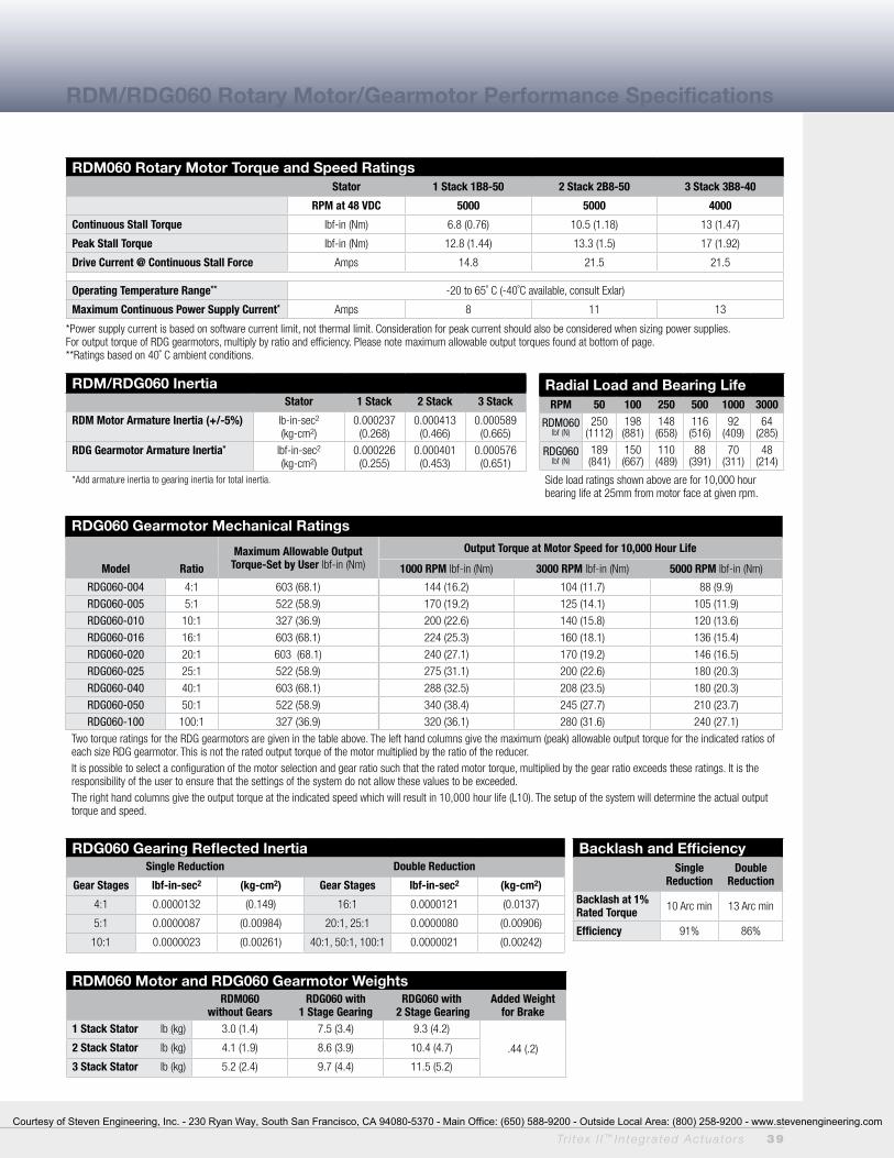
Tr i tex I I ™ In tegra ted Actua to rs 39
RDM/RDG060 Rotary Motor/Gearmotor Performance Specifications
RDM060 Rotary Motor Torque and Speed RatingsStator 1 Stack 1B8-50 2 Stack 2B8-50 3 Stack 3B8-40
RPM at 48 VDC 5000 5000 4000
Continuous Stall Torque lbf-in (Nm) 6.8 (0.76) 10.5 (1.18) 13 (1.47)
Peak Stall Torque lbf-in (Nm) 12.8 (1.44) 13.3 (1.5) 17 (1.92)
Drive Current @ Continuous Stall Force Amps 14.8 21.5 21.5
Operating Temperature Range** -20 to 65˚ C (-40˚C available, consult Exlar)
Maximum Continuous Power Supply Current* Amps 8 11 13
* Power supply current is based on software current limit, not thermal limit. Consideration for peak current should also be considered when sizing power supplies.For output torque of RDG gearmotors, multiply by ratio and efficiency. Please note maximum allowable output torques found at bottom of page.**Ratings based on 40˚ C ambient conditions.
RDM/RDG060 Inertia Stator 1 Stack 2 Stack 3 Stack
RDM Motor Armature Inertia (+/-5%) lb-in-sec2
(kg-cm2)0.000237
(0.268)0.000413
(0.466)0.000589
(0.665)
RDG Gearmotor Armature Inertia* lbf-in-sec2
(kg-cm2)0.000226
(0.255)0.000401
(0.453)0.000576
(0.651)*Add armature inertia to gearing inertia for total inertia.
RDG060 Gearmotor Mechanical Ratings
Maximum Allowable Output Torque-Set by User lbf-in (Nm)
Output Torque at Motor Speed for 10,000 Hour Life
Model Ratio 1000 RPM lbf-in (Nm) 3000 RPM lbf-in (Nm) 5000 RPM lbf-in (Nm)
RDG060-004 4:1 603 (68.1) 144 (16.2) 104 (11.7) 88 (9.9)
RDG060-005 5:1 522 (58.9) 170 (19.2) 125 (14.1) 105 (11.9)
RDG060-010 10:1 327 (36.9) 200 (22.6) 140 (15.8) 120 (13.6)
RDG060-016 16:1 603 (68.1) 224 (25.3) 160 (18.1) 136 (15.4)
RDG060-020 20:1 603 (68.1) 240 (27.1) 170 (19.2) 146 (16.5)
RDG060-025 25:1 522 (58.9) 275 (31.1) 200 (22.6) 180 (20.3)
RDG060-040 40:1 603 (68.1) 288 (32.5) 208 (23.5) 180 (20.3)
RDG060-050 50:1 522 (58.9) 340 (38.4) 245 (27.7) 210 (23.7)
RDG060-100 100:1 327 (36.9) 320 (36.1) 280 (31.6) 240 (27.1)
Two torque ratings for the RDG gearmotors are given in the table above. The left hand columns give the maximum (peak) allowable output torque for the indicated ratios of each size RDG gearmotor. This is not the rated output torque of the motor multiplied by the ratio of the reducer.It is possible to select a configuration of the motor selection and gear ratio such that the rated motor torque, multiplied by the gear ratio exceeds these ratings. It is the responsibility of the user to ensure that the settings of the system do not allow these values to be exceeded.The right hand columns give the output torque at the indicated speed which will result in 10,000 hour life (L10). The setup of the system will determine the actual output torque and speed.
RDG060 Gearing Reflected InertiaSingle Reduction Double Reduction
Gear Stages lbf-in-sec2 (kg-cm2) Gear Stages lbf-in-sec2 (kg-cm2)
4:1 0.0000132 (0.149) 16:1 0.0000121 (0.0137)
5:1 0.0000087 (0.00984) 20:1, 25:1 0.0000080 (0.00906)
10:1 0.0000023 (0.00261) 40:1, 50:1, 100:1 0.0000021 (0.00242)
Backlash and EfficiencySingle
ReductionDouble
Reduction
Backlash at 1% Rated Torque 10 Arc min 13 Arc min
Efficiency 91% 86%
RDM060 Motor and RDG060 Gearmotor WeightsRDM060
without GearsRDG060 with
1 Stage GearingRDG060 with
2 Stage GearingAdded Weight
for Brake1 Stack Stator lb (kg) 3.0 (1.4) 7.5 (3.4) 9.3 (4.2)
.44 (.2)2 Stack Stator lb (kg) 4.1 (1.9) 8.6 (3.9) 10.4 (4.7)
3 Stack Stator lb (kg) 5.2 (2.4) 9.7 (4.4) 11.5 (5.2)
Radial Load and Bearing LifeRPM 50 100 250 500 1000 3000
RDM060lbf (N)
250 (1112)
198 (881)
148 (658)
116 (516)
92 (409)
64 (285)
RDG060 lbf (N)
189 (841)
150 (667)
110 (489)
88 (391)
70 (311)
48 (214)
Side load ratings shown above are for 10,000 hour bearing life at 25mm from motor face at given rpm.
Courtesy of Steven Engineering, Inc. - 230 Ryan Way, South San Francisco, CA 94080-5370 - Main Office: (650) 588-9200 - Outside Local Area: (800) 258-9200 - www.stevenengineering.com

40 Tr i tex I I ™ In tegra ted Actua to rs
RDM/RDG075 Rotary Motor/Gearmotor Performance Specifications
RDM075 Rotary Motor Torque and Speed RatingsStator 1 Stack 1B8-40 2 Stack 2B8-30 3 Stack 3B8-20
RPM at 48 VDC 4000 3000 2000
Continuous Stall Torque lbf-in (Nm) 13 (1.46) 18.5 (2.09) 29 (3.28)
Peak Stall Torque lbf-in (Nm) 18.9 (2.08) 28 (3.16) 41 (4.63)
Drive Current @ Continuous Stall Force Amps 22 22 22
Operating Temperature Range** -20 to 65˚ C (-40˚C available, consult Exlar)
Maximum Continuous Power Supply Current* Amps 15 18 18
* Power supply current is based on software current limit, not thermal limit. Consideration for peak current should also be considered when sizing power supplies.For output torque of RDG gearmotors, multiply by ratio and efficiency. Please note maximum allowable output torques shown below.**Ratings based on 40˚ C ambient conditions.
RDM/RDG075 Inertia Stator 1 Stack 2 Stack 3 Stack
RDM Motor Armature Inertia (+/-5%) lb-in-sec2
(kg-cm2)0.000545 (0.6158)
0.000973 (1.0996)
0.001401 (1.5834)
RDG Gearmotor Armature Inertia* (+/-5%)
lbf-in-sec2
(kg-cm2)0.000660 (0.7450)
0.001068 (1.2057)
0.001494 (1.6868)
*Add armature inertia to gearing inertia for total inertia.
RDG075 Gearmotor Mechanical Ratings
Maximum Allowable Output Torque-Set by User lbf-in (Nm)
Output Torque at Motor Speed for 10,000 Hour Life
Model Ratio 1000 RPM lbf-in (Nm) 2500 RPM lbf-in (Nm) 4000 RPM lbf-in (Nm)
RDG075-004 4:1 1618 (182.8) 384 (43.4) 292 (32.9) 254 (28.7)
RDG075-005 5:1 1446 (163.4) 395 (44.6) 300 (33.9) 260 (29.4)
RDG075-010 10:1 700 (79.1) 449 (50.7) 341 (38.5) 296 (33.4)
Two torque ratings for the RDG gearmotors are given in the table above. The left hand columns give the maximum (peak) allowable output torque for the indicated ratios of each size RDG gearmotor. This is not the rated output torque of the motor multiplied by the ratio of the reducer.It is possible to select a configuration of the motor selection and gear ratio such that the rated motor torque, multiplied by the gear ratio exceeds these ratings. It is the responsibility of the user to ensure that the settings of the system do not allow these values to be exceeded.The right hand columns give the output torque at the indicated speed which will result in 10,000 hour life (L10). The setup of the system will determine the actual output torque and speed.
Radial Load and Bearing LifeRPM 50 100 250 500 1000 3000
RDM075lbf (N)
278(1237)
220 (979)
162 (721)
129 (574)
102 (454)
71 (316)
RDG075 lbf (N)
343 (1526)
272 (1210)
200 (890)
159 (707)
126 (560)
88 (391)
Side load ratings shown above are for 10,000 hour bearing life at 25mm from motor face at given rpm.
RDG075 Gearing Reflected InertiaSingle Reduction (+/-5%)
Gear Stages lbf-in-sec2 (kg-cm2)
4:1 0.000095 (0.107)
5:1 0.000062 (0.069)
10:1 0.000117 (0.019)
Backlash and EfficiencySingle Reduction
Backlash at 1% Rated Torque 10 Arc min
Efficiency 91%
RDM075 Motor and RDG075 Gearmotor WeightsRDM075 without Gears RDG075 with 1 Stage Gearing Added Weight for Brake
1 Stack Stator lb (kg) 7.4 (3.4) 9.8 (4.4)
0.8 (0.4)2 Stack Stator lb (kg) 9.2 (4.2) 11.6 (5.3)
3 Stack Stator lb (kg) 11 (4.9) 13.4 (6.1)
Courtesy of Steven Engineering, Inc. - 230 Ryan Way, South San Francisco, CA 94080-5370 - Main Office: (650) 588-9200 - Outside Local Area: (800) 258-9200 - www.stevenengineering.com
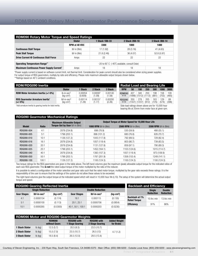
Tr i tex I I ™ In tegra ted Actua to rs 41
RDM/RDG090 Rotary Motor/Gearmotor Performance Specifications
RDM090 Rotary Motor Torque and Speed RatingsStator 1 Stack 1B8-33 2 Stack 2B8-18 3 Stack 3B8-14
RPM at 48 VDC 3300 1800 1400
Continuous Stall Torque lbf-in (Nm) 17 (1.92) 28 (3.16) 41 (4.63)
Peak Stall Torque lbf-in (Nm) 21.8 (2.46) 36 (4.07) 52.8 (5.97)
Drive Current @ Continuous Stall Force Amps 22 22 22
Operating Temperature Range** -20 to 65˚ C (-40˚C available, consult Exlar)
Maximum Continuous Power Supply Current* Amps 18 18 18
*Power supply current is based on software current limit, not thermal limit. Consideration for peak current should also be considered when sizing power supplies.For output torque of RDG gearmotors, multiply by ratio and efficiency. Please note maximum allowable output torques shown below.**Ratings based on 40˚ C ambient conditions.
RDM/RDG090 Inertia Stator 1 Stack 2 Stack 3 Stack
RDM Motor Armature Inertia (+/-5%) lb-in-sec2
(kg-cm2)0.00054 (0.609)
0.00097 (1.09)
0.00140 (1.58)
RDG Gearmotor Armature Inertia* (+/-5%)
lbf-in-sec2
(kg-cm2)0.00114
(1.29)0.00157
(1.77)0.00200
(2.26)*Add armature inertia to gearing inertia for total inertia.
RDG090 Gearmotor Mechanical Ratings
Maximum Allowable Output Torque-Set by User lbf-in (Nm)
Output Torque at Motor Speed for 10,000 Hour Life
Model Ratio 1000 RPM lbf-in (Nm) 2500 RPM lbf-in (Nm) 3300 RPM lbf-in (Nm)
RDG090-004 4:1 2078 (234.8) 698 (78.9) 530 (59.9) 488 (55.1)
RDG090-005 5:1 1798 (203.1) 896 (101.2) 680 (76.8) 626 (70.7)
RDG090-010 10:1 1126 (127.2) 1043 (117.8) 792 (89.5) 729 (82.4)
RDG090-016 16:1 2078 (234.8) 1057 (119.4) 803 (90.7) 739 (83.5)
RDG090-020 20:1 2078 (234.8) 1131 (127.8) 859 (97.1) 790 (89.3)
RDG090-025 25:1 1798 (203.1) 1452 (164.1) 1103 (124.6) 1015 (114.7)
RDG090-040 40:1 2078 (234.8) 1392 (157.3) 1057 (119.4) 973 (109.9)
RDG090-050 50:1 1798 (203.1) 1787 (201.9) 1358 (153.4) 1249 (141.1)
RDG090-100 100:1 1126 (127.2) 1100 (124.3) 1100 (124.3) 1100 (124.3)
Two torque ratings for the RDG gearmotors are given in the table above. The left hand columns give the maximum (peak) allowable output torque for the indicated ratios of each size RDG gearmotor. This is not the rated output torque of the motor multiplied by the ratio of the reducer.It is possible to select a configuration of the motor selection and gear ratio such that the rated motor torque, multiplied by the gear ratio exceeds these ratings. It is the responsibility of the user to ensure that the settings of the system do not allow these values to be exceeded.The right hand columns give the output torque at the indicated speed which will result in 10,000 hour life (L10). The setup of the system will determine the actual output torque and speed.
RDG090 Gearing Reflected InertiaSingle Reduction Double Reduction
Gear Stages lbf-in-sec2 (kg-cm2) Gear Stages lbf-in-sec2 (kg-cm2)
4:1 0.0000154 (0.174) 16:1 0.000115 (0.130)
5:1 0.0000100 (0.113) 20:1, 25:1 0.0000756 (0.0854)
10:1 0.0000265 (0.0300) 40:1, 50:1, 100:1 0.0000203 (0.0230)
Backlash and EfficiencySingle
ReductionDouble
Reduction
Backlash at 1% Rated Torque 10 Arc min 13 Arc min
Efficiency 91% 86%
RDM090 Motor and RDG090 Gearmotor WeightsRDM090
without GearsRDG090 with
1 Stage GearingRDG090 with
2 Stage GearingAdded Weight
for Brake1 Stack Stator lb (kg) 12.5 (5.7) 20.5 (9.3) 23.5 (10.7)
4.7 (1.2)2 Stack Stator lb (kg) 15.5 (7.0) 23.5 (10.7) 26.5 (12)
3 Stack Stator lb (kg) 18.5 (8.4) 26.5 (12.0) 29.5 (13.4)
Radial Load and Bearing LifeRPM 50 100 250 500 1000 3000
RDM090lbf (N)
427(1899)
340 (1512)
250 (1112)
198 (881)
158 (703)
109 (485)
RDG090 lbf (N)
350 (1557)
278 (1237)
205 (912)
163 (725)
129 (574)
89 (396)
Side load ratings shown above are for 10,000 hour bearing life at 25mm from motor face at given rpm.
Courtesy of Steven Engineering, Inc. - 230 Ryan Way, South San Francisco, CA 94080-5370 - Main Office: (650) 588-9200 - Outside Local Area: (800) 258-9200 - www.stevenengineering.com

42 Tr i tex I I ™ In tegra ted Actua to rs
TDM/X060 Linear Actuator Dimensions
TDM/X060 Double Side Mount or Extended Tie Rod Mount
TDM/X060 Side Trunnion Mount or Rear Clevis Mount
TDM/X060 Front, Rear, or Front and Rear Flange Mount
DIM 3 inch (75 mm) stroke in (mm)
6 inch (150 mm) stroke in (mm)
10 inch (250 mm) stroke in (mm)
12 inch (300 mm) stroke in (mm)
A 9.79 (248.7) 12.79 (324.9) 16.79 (426.5) 18.79 (477.3)
B 5.62 (142.8) 8.62 (218.9) 12.62 (320.6) 14.62 (371.4)
C 3.00 (76.2) 6.00 (152.4) 10.00 (254.0) 12.00 (304.8)
D 11.10 (281.9) 14.10 (358.1) 18.10 (459.7) 20.10 (510.5)
Note: Add 1.75 inches to dimensions “A”, “B” and “D” if ordering a brake. Add .50 inches to dimensions “A”, “C” and “D” and dimension if ordering a splined 1 main rod.
2.3660
1.1830.0
2.5564.7
BC
2.3660
1.1830.0
Single Side MountOn This Side
.7519.1
1.0025.4
.174.3
1.500+-.000.003
38.1 -0.000.08 .25
6.41
Dim "A"
Dim "B"
4.53115.1
1.1830.0
"J" & "K" = Ø 6mm +.000/-.013 6mm"S" & "D" = Ø .2500 +.0000/-.0005 .250
1.0025.4
1.7143.5
"E" = #10-24 UNC"M" = M5x0.8
"S" & "D" = 1/4-20 UNC"J" & "K" = M6x1.0"S" & "J" = 4X, "D" & "K" = 8X
5.24133.0
3.2482.2
2.3660
2.3660
1.0025.4
1.0025.4
Dim "C"
Dim "A"
Dim "D"
.8822.4
R.6315.9
"C" = .500 +.002/-001"G" 12mm +.05/-.03
1.5038.1
"T" = 1.000 .001"Q" 25mm .03
.7519.1
1.5439.0
4.46113.3
2.3660.0
1.9750.0
3.94100.0
3.1580.0 4X .25
6.4
1.5740.0
4X .246.0
.4411.2
1.0025.4
DIM "A"
.4712.0
4.46113.3
3.94100.0
2.3660.0
4X .256.4
3.1580.0
1.5740.0
1.9750.0
4X .246.0
Courtesy of Steven Engineering, Inc. - 230 Ryan Way, South San Francisco, CA 94080-5370 - Main Office: (650) 588-9200 - Outside Local Area: (800) 258-9200 - www.stevenengineering.com
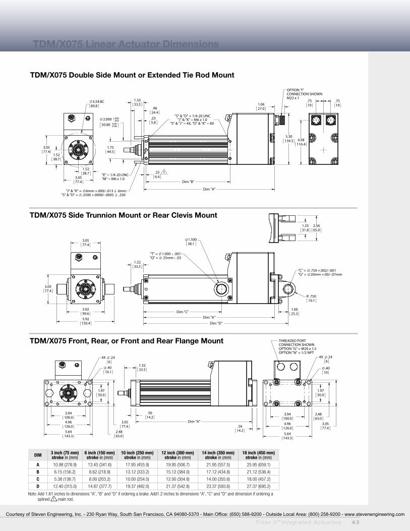
Tr i tex I I ™ In tegra ted Actua to rs 43
TDM/X075 Linear Actuator Dimensions
TDM/X075 Double Side Mount or Extended Tie Rod Mount
TDM/X075 Side Trunnion Mount or Rear Clevis Mount
TDM/X075 Front, Rear, or Front and Rear Flange Mount
1.5238.7
1.5238.7
3.0577.4
3.0577.4
3.5489.8
BC
.256.4
1
.9624.4
1.3233.5
.235.8
2.000 +-
.000
.003
50.80 -0.000.08
Dim "B"
Dim "A"
5.30134.5
"J" & "K" = 6mm +.000/-.013 6mm"S" & "D" = .2500 +.0000/-.0005 .250
"S" & "D" = 1/4-20 UNC"J" & "K" = M6 x 1.0
"S" & "J" = 4X, "D" & "K" = 8X
1.7544.5
1.0627.0
"E" = 1/4-20 UNC"M" = M6 x 1.0
OPTION "I"CONNECTION SHOWNM23 x 1
.7519
4.58116.4
.7519
3.0577.4
5.92150.4
3.9299.6
3.0577.4
Dim "C" 1.00
25.3
1.3233.5
"T" = 1.000 .001"Q" = 25mm .03
1.50038.1
Dim "A"
Dim "D"
R .75019.1
"C" = .750 +.002/-.001"G" = 20mm +.00/-.07mm
5.64143.3
4.96126.0
2.4863.0
3.0577.4
.4010.1
3.94100.0
1.9750.0
4X .246
1.3233.5
.5614.2
.5614.2
Dim "A"
5.64143.3
4.96126.0
2.4863.0
3.0577.4
.4010
3.94100.0
1.9750.0
4X .246
THREADED PORTCONNECTION SHOWNOPTION "G" = M20 x 1.5OPTION "N" = 1/2 NPT
1.2531.8
2.5665.0
DIM 3 inch (75 mm) stroke in (mm)
6 inch (150 mm) stroke in (mm)
10 inch (250 mm) stroke in (mm)
12 inch (300 mm) stroke in (mm)
14 inch (350 mm) stroke in (mm)
18 inch (450 mm) stroke in (mm)
A 10.98 (278.9) 13.45 (341.6) 17.95 (455.9) 19.95 (506.7) 21.95 (557.5) 25.95 (659.1)
B 6.15 (156.2) 8.62 (218.9) 13.12 (333.2) 15.12 (384.0) 17.12 (434.8) 21.12 (536.4)
C 5.38 (136.7) 8.00 (203.2) 10.00 (254.0) 12.00 (304.8) 14.00 (355.6) 18.00 (457.2)
D 12.40 (315.0) 14.87 (377.7) 19.37 (492.0) 21.37 (542.8) 23.37 (593.6) 27.37 (695.2)
Note: Add 1.61 inches to dimensions “A”, “B” and “D” if ordering a brake. Add1.2 inches to dimensions “A”, “C” and “D” and dimension if ordering a splined 1 main rod.
Courtesy of Steven Engineering, Inc. - 230 Ryan Way, South San Francisco, CA 94080-5370 - Main Office: (650) 588-9200 - Outside Local Area: (800) 258-9200 - www.stevenengineering.com
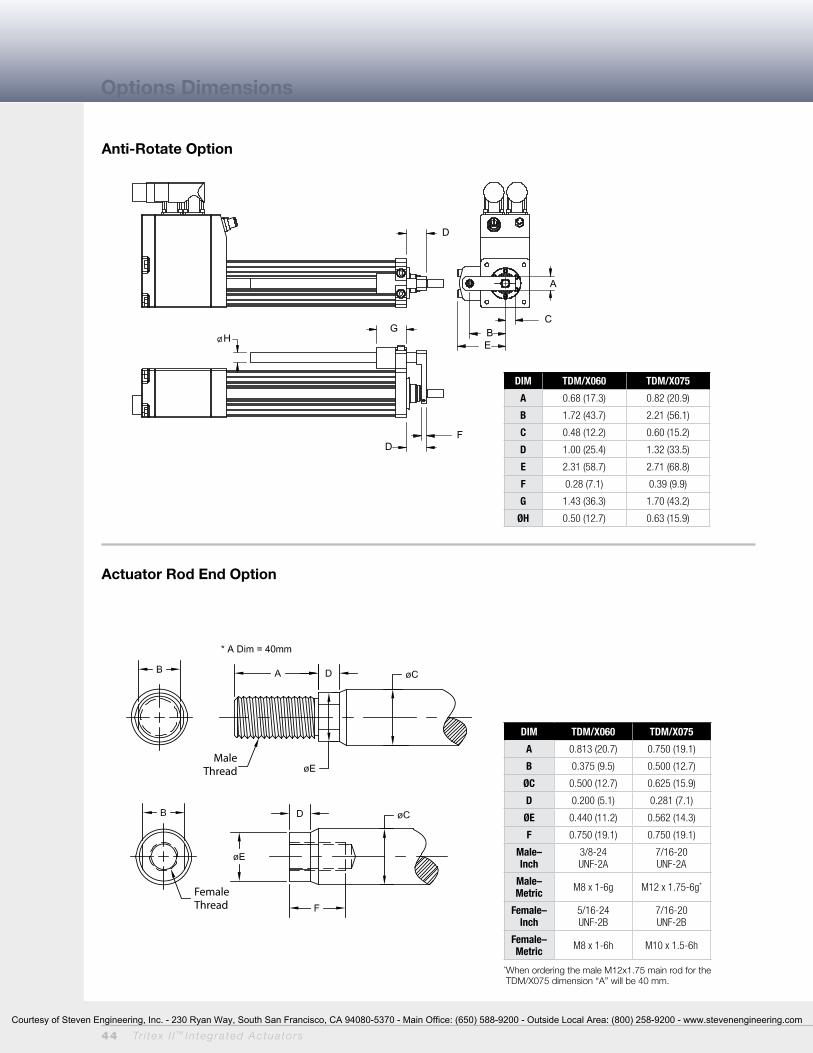
44 Tr i tex I I ™ In tegra ted Actua to rs
Options Dimensions
Anti-Rotate Option
Actuator Rod End Option
MaleThread
FemaleThread
A
C B E
D
H
F D
G
DIM TDM/X060 TDM/X075
A 0.813 (20.7) 0.750 (19.1)
B 0.375 (9.5) 0.500 (12.7)
ØC 0.500 (12.7) 0.625 (15.9)
D 0.200 (5.1) 0.281 (7.1)
ØE 0.440 (11.2) 0.562 (14.3)
F 0.750 (19.1) 0.750 (19.1)
Male–Inch
3/8-24UNF-2A
7/16-20UNF-2A
Male–Metric M8 x 1-6g M12 x 1.75-6g*
Female–Inch
5/16-24UNF-2B
7/16-20UNF-2B
Female–Metric M8 x 1-6h M10 x 1.5-6h
* When ordering the male M12x1.75 main rod for the TDM/X075 dimension “A” will be 40 mm.
DIM TDM/X060 TDM/X075
A 0.68 (17.3) 0.82 (20.9)
B 1.72 (43.7) 2.21 (56.1)
C 0.48 (12.2) 0.60 (15.2)
D 1.00 (25.4) 1.32 (33.5)
E 2.31 (58.7) 2.71 (68.8)
F 0.28 (7.1) 0.39 (9.9)
G 1.43 (36.3) 1.70 (43.2)
ØH 0.50 (12.7) 0.63 (15.9)
Courtesy of Steven Engineering, Inc. - 230 Ryan Way, South San Francisco, CA 94080-5370 - Main Office: (650) 588-9200 - Outside Local Area: (800) 258-9200 - www.stevenengineering.com

Tr i tex I I ™ In tegra ted Actua to rs 45
Clevis Pin
DIM
TDM/X060 TDM/X075
SRM038 in (mm) SRM044 in (mm)
A 1.625 (41.3) 1.81 (46.0)
ØB .375 (9.525) 0.438 (11.13)
C .906 (23.0) 1.06 (26.9)
D 1.0 (25.6) 1.13 (28.7)
E 12 Deg 14 Deg
F .406 (10.3) 0.44 (11.1)
G .500 (12.7) 0.56 (14.2)
H .688 (17.7) 0.75 (19.1)
J .562 (14.3) 0.63 (16.0)
K 3/8-24 7/16-20
DIMTDM/X060 TDM/X075
RE038 in (mm) RE050 in (mm)
ØA 0.50 (12.7) 0.50 (12.7)
B 0.560 (14.2) 0.75 (19.1)
C 1.000 (25.4) 1.50 (38.1)
D 0.500 (12.7) 0.75 (19.1)
E 0.25 x 45˚ (6.35) 0.63 (15.9)
F 3/8-24 7/16-20
Spherical Rod Eye
Rod Eye
DIM
TDM/X060 TDM/X075
RC038 in (mm) RC050 in (mm)
A .787 (20) .75 (19.1)
B .787 (20) .75 (19.1)
C 1.574 (40) 1.50 (38.1)
D 0.183 (4.65) 0.50 (12.7)
E 0.375 (9.5) 0.765 (19.43)
ØF 0.375 (9.5) 0.50 (12.7)
ØG 0.75 (19.1) 1.00 (25.4)
H N/A 1.00 (25.4)
ØJ N/A 1.00 (25.4)
K 3/8-24 7/16-20
Rod Clevis
DIM
TDM/X060 TDM/X075
CP050 in (mm)Rear Clevis,
RE050 & RC050
CP075 in (mm)Rear Clevis
A 2.28 (57.9) 3.09 (78.5)
B 1.94 (49.28) 2.72 (69.1)
C 0.17 (4.32) 1.19 (4.82)
ØD 0.50 (12.7) -0.001/-.002
0.75 (19.1)-0.001/-.002
ØE 0.095 (2.41) 0.14 (3.56)
Rod End Attachment Dimensions
Courtesy of Steven Engineering, Inc. - 230 Ryan Way, South San Francisco, CA 94080-5370 - Main Office: (650) 588-9200 - Outside Local Area: (800) 258-9200 - www.stevenengineering.com

46 Tr i tex I I ™ In tegra ted Actua to rs
RDM/RDG060 Rotary Motor/Gearmotor Dimensions
RDM060 Dimensions
RDG060 Dimensions
Without Brake Option
DIM 1 Stack Stator1 Stage Gearhead
2 Stack Stator1 Stage Gearhead
3 Stack Stator1 Stage Gearhead
A 9.434 (240) 10.684 (271) 11.934 (303)
DIM 1 Stack Stator2 Stage Gearhead
2 Stack Stator2 Stage Gearhead
3 Stack Stator2 Stage Gearhead
A 10.479 (266) 11.729 (298) 12.979 (330)
Without Brake Option
DIM 1 Stack Stator 2 Stack Stator 3 Stack Stator
A 7.146 (185.1) 8.396 (213.3) 9.646 (245.0)
With Brake Option
DIM 1 Stack Stator 2 Stack Stator 3 Stack Stator
A 7.856 (199.5) 9.106 (231.3) 10.356 (263.0)
With Brake Option
DIM 1 Stack Stator1 Stage Gearhead
2 Stack Stator1 Stage Gearhead
3 Stack Stator1 Stage Gearhead
A 10.144 (258) 11.394 (289) 12.644 (321)
DIM 1 Stack Stator2 Stage Gearhead
2 Stack Stator2 Stage Gearhead
3 Stack Stator2 Stage Gearhead
A 11.189 (284) 12.439 (316) 13.689 (348)
2.3660
.6315.9
.1969
.1957[5mm(h9)]
4X .225.6
2.7570.0
1.96811.9675
[50mm(g6)]
2.3660
1.1830.0
Dim "A"
.102.5
.348.7
1.1830.0
.5512
.5507[14mm(h6)]
4.53115.1
.7920.0
1.6341.4
2.3660
1.96811.9675
[50mm(g6)]2.7570.0
B.C.
4X .225.5
.7017.9
2.3660
.1969
.1957[5mm(h9)]
Dim "A"
1.18130.0
.123.0
.389.7
1.4336.3
.6302
.6298[16mm(j6)]
4.53115.1
.9825.0
1.6341.4
Courtesy of Steven Engineering, Inc. - 230 Ryan Way, South San Francisco, CA 94080-5370 - Main Office: (650) 588-9200 - Outside Local Area: (800) 258-9200 - www.stevenengineering.com
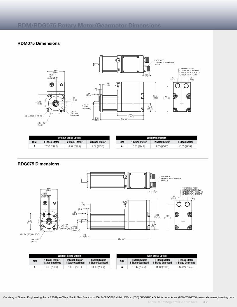
Tr i tex I I ™ In tegra ted Actua to rs 47
RDM/RDG075 Rotary Motor/Gearmotor Dimensions
RDM075 Dimensions
RDG075 Dimensions
Without Brake Option
DIM 1 Stack Stator1 Stage Gearhead
2 Stack Stator1 Stage Gearhead
3 Stack Stator1 Stage Gearhead
A 9.19 (233.4) 10.19 (258.8) 11.19 (284.2)
Without Brake Option
DIM 1 Stack Stator 2 Stack Stator 3 Stack Stator
A 7.57 (192.3) 8.57 (217.7) 9.57 (243.1)
With Brake Option
DIM 1 Stack Stator 2 Stack Stator 3 Stack Stator
A 8.85 (224.8) 9.85 (250.2) 10.85 (275.6)
With Brake Option
DIM 1 Stack Stator1 Stage Gearhead
2 Stack Stator1 Stage Gearhead
3 Stack Stator1 Stage Gearhead
A 10.42 (264.7) 11.42 (290.1) 12.42 (315.5)
3.0577.4
.6315.9
.1969
.1957[5mm h9]
4X .26 6.5 ON BC
3.7495.0
BC
2.55872.5580
[65mm g6]
3.0577.4
DIM "A"
.112.8
.389.5
5.30134.5
1.5038.1
.5512.5508
[14mm h6]
1.1830.0
4.59116.6
.7920.0
4.61117.0
.7519.1
.7519.1
THREADED PORTCONNECTION SHOWNOPTION "G" = M20 x 1.5OPTION "N" = 1/2 NPT1.06
27.0
OPTION "I"CONNECTION SHOWNM23 x 1
3.0577.4
.1969
.1957[5mm h9]
4X .26 6.5 ON BC
3.7495.0
BC
2.55872.5580
[65mm g6]
3.0577.4
1.5038.1
5.30134.5
DIM "A"
1.1830.0
.4511.5
.112.8
.7920.0
.6302
.6298[16mm j6]
1.0627.0
OPTION "I"CONNECTION SHOWNM23 x 1
.7519.1
.7519.1
4.61117.0
THREADED PORTCONNECTION SHOWNOPTION "G" = M20 x 1.5OPTION "N" = 1/2 NPT
Courtesy of Steven Engineering, Inc. - 230 Ryan Way, South San Francisco, CA 94080-5370 - Main Office: (650) 588-9200 - Outside Local Area: (800) 258-9200 - www.stevenengineering.com

48 Tr i tex I I ™ In tegra ted Actua to rs
RDM/RDG090 Rotary Motor/Gearmotor Dimensions
RDM090 Dimensions
3.5490
4X .287.0
.2362
.2350[6mm(h9)]
.8521.5
3.14923.1485
[80mm(g6)]3.94100.0
B.C.
3.5490
.123.0
.3910.0
1.5739.9
.7480
.7475[19mm(h6)]
Dim "A"
1.7745.0
5.30134.5
1.2632.0
4.58116.4
.7519.1
.7519.1
THREADED PORTCONNECTION SHOWNOPTION "G" = M20 x 1.5OPTION "N" = 1/2 NPT
3.0577.4
3.8798.3
1.0627.0
OPTION "I"CONNECTION SHOWNM23 x 1
Without Brake Option
DIM 1 Stack Stator 2 Stack Stator 3 Stack Stator
A 7.69 (195.3) 8.69 (220.7) 9.69 (246.1)
With Brake Option
DIM 1 Stack Stator 2 Stack Stator 3 Stack Stator
A 9.0 (228.6) 10.00 (254.0) 11.00 (279.4)
Courtesy of Steven Engineering, Inc. - 230 Ryan Way, South San Francisco, CA 94080-5370 - Main Office: (650) 588-9200 - Outside Local Area: (800) 258-9200 - www.stevenengineering.com
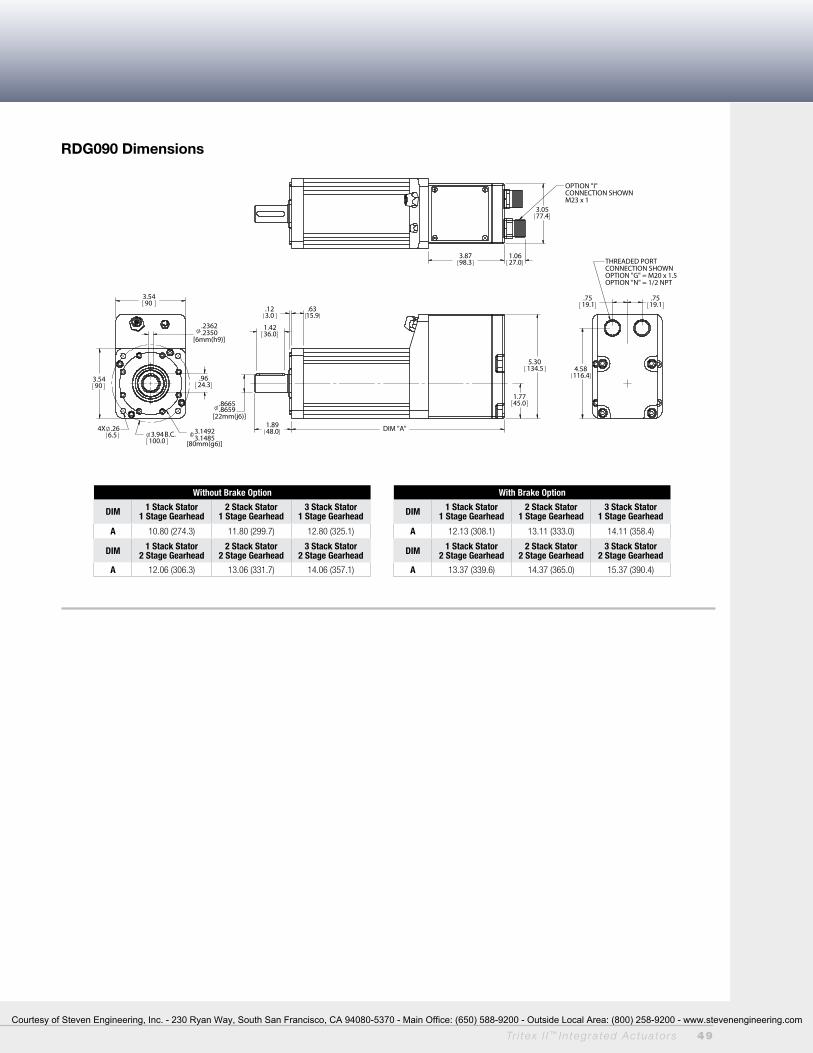
Tr i tex I I ™ In tegra ted Actua to rs 49
RDG090 Dimensions
4.58116.4
.7519.1
.7519.1
THREADED PORTCONNECTION SHOWNOPTION "G" = M20 x 1.5OPTION "N" = 1/2 NPT
1.0627.0
OPTION "I"CONNECTION SHOWNM23 x 1
1.7745.0
5.30134.5
1.4236.0
.123.0
.6315.9
DIM "A" 1.8948.0
.8665
.8659[22mm(j6)]
3.5490
.2362
.2350[6mm(h9)]
.9624.3
3.14923.1485
[80mm(g6)]3.94
100.0 B.C.
4X .266.5
3.5490
3.8798.3
3.0577.4
Without Brake Option
DIM 1 Stack Stator1 Stage Gearhead
2 Stack Stator1 Stage Gearhead
3 Stack Stator1 Stage Gearhead
A 10.80 (274.3) 11.80 (299.7) 12.80 (325.1)
DIM 1 Stack Stator2 Stage Gearhead
2 Stack Stator2 Stage Gearhead
3 Stack Stator2 Stage Gearhead
A 12.06 (306.3) 13.06 (331.7) 14.06 (357.1)
With Brake Option
DIM 1 Stack Stator1 Stage Gearhead
2 Stack Stator1 Stage Gearhead
3 Stack Stator1 Stage Gearhead
A 12.13 (308.1) 13.11 (333.0) 14.11 (358.4)
DIM 1 Stack Stator2 Stage Gearhead
2 Stack Stator2 Stage Gearhead
3 Stack Stator2 Stage Gearhead
A 13.37 (339.6) 14.37 (365.0) 15.37 (390.4)
Courtesy of Steven Engineering, Inc. - 230 Ryan Way, South San Francisco, CA 94080-5370 - Main Office: (650) 588-9200 - Outside Local Area: (800) 258-9200 - www.stevenengineering.com
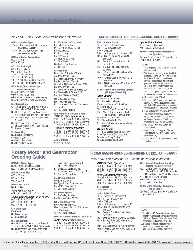
50 Tr i tex I I ™ In tegra ted Actua to rs
RDM/G = Motor TypeRDM = Tritex II DC Rotary MotorRDG = Tritex II DC Rotary Gearmotor
AAA = Frame Size060 = 60 mm075 = 75 mm090 = 90 mm
BBB = Gear RatioBlank = RDMSingle Reduction Ratios 004 = 4:1 005 = 5:1 010 = 10:1Double Reduction Ratios (NA on 75 mm)016 = 16:1 020 = 20:1025 = 25:1 040 = 40:1050 = 50:1 100 = 100:1
C = Shaft TypeK = KeyedR = Smooth/RoundX = Special Shaft
D = ConnectionsG = Std straight threaded port w/internal
terminals, M20x1.5 (75 & 90 mm only)N = NPT threaded port internal terminals,
1/2" NPT (75 & 90 mm only)
I = Intercontec style – Exlar std, M23 Style Connector
B = Embedded Leads, 3 ft. std.J = Embedded Leads, w/“I” plug, 3 ft. std.X = Custom Connectivity
E = Housing OptionsG = Exlar StandardH = Type III Hard Coat AnodizedF = White Epoxy CoatingX = Special or Custom
F = Brake OptionS = No Brake, StandardB = Electric Brake, 24 VDC
GG = Feedback TypeHD = Analog Hall DeviceIE = Incremental Encoder, 8192 Count
ResolutionAF = Absolute Feedback
HHH-HH = Motor Stators - All 8 PoleRDM/G060 Stator Specifications 1B8-50 = 1 Stack, 48 VDC, 5000 rpm2B8-50 = 2 Stack, 48 VDC, 5000 rpm3B8-40 = 3 Stack, 48 VDC, 4000 rpm
RDM/G075 Stator Specifications 1B8-40 = 1 Stack, 48 VDC, 4000 rpm2B8-30 = 2 Stack, 48 VDC, 3000 rpm3B8-20 = 3 Stack, 48 VDC, 2000 rpmRDM/G090 Stator Specifications 1B8-33 = 1 Stack, 48 VDC, 3300 rpm2B8-18 = 2 Stack, 48 VDC, 1800 rpm3B8-14 = 3 Stack, 48 VDC, 1400 rpm
III = Voltage048= 12-48 VDC
JJJ = Option BoardSIO = Standard I/O InterconnectIA4 = + 4-20 mA Analog I/OCOP = CANOpenCON = CANOpen, non-connecdorized2
EIP = SIO plus EtherNet/IP with M12 connector
EIN = SIO plus EtherNet/IP without M12 connector2
PIO = SIO plus Profinet IO w/M12 connectorPIN = SIO plus Profinet IO without M12
connector2
TCP = SIO plus Modbus TCP w/M12 connectorTCN = SIO plus Modbus TCP without M12
connector2
XX = Special Travel and Housing Options (multiples possible)
HW = Manual Drive, Handwheel with Interlock Switch (75 & 90 mm only)
SD = Manual Drive, Side (75 & 90 mm only)XH = Special Housing OptionsXM = Special Motor OptionsXL = Special Lubrication1
##### = Part Number Designator for Specials
Optional 5 digit assigned PN to designate unique model no.
NOTES:1. To achieve -40˚ C operating temperature,
specify -XL in the actuator model mask and define Mobilgrease 28 in order notes. Other special lubricants are also available.
2. Requires customer supplied Ethernet cable through I/O port for Class 1 Div 2 compliance only. Also N/A on 60 mm.
Linear Actuator Ordering Guide
Rotary Motor and Gearmotor Ordering Guide
AAA = Actuator TypeTDM = Tritex II Linear Actuator, standard
mechanical capacityTDX = Tritex II Linear Actuator, high
mechanical capacity
BBB = Actuator Frame Size060 = 60 mm075 = 75 mm
CC = Stroke Length03 = 3 inch (76 mm) 06 = 6 inch (150 mm)10 = 10 inch (254 mm)12 = 12 inch (305 mm)14 = 14 inch (356 mm) (75 mm only)18 = 18 inch (457 mm) (75 mm only)
DD = Lead (linear travel per screw revolution)
01 = 0.1 inch (2.54 mm)02 = 0.2 inch (5.08 mm)04 = 0.4 inch (10.16 mm) (60 mm only)05 = 0.5 inch (12.7 mm) (75 mm only)
E = ConnectionsG = Std Straight Threaded Port w/internal
terminals, M20x1.5 (75 mm only)N = NPT Threaded Port via Adapter with
Internal Terminals, 1/2" NPT (75 mm only)I = Intercontec Style - Exlar std, M23 Style
ConnectorB = Embedded Leads, 3 ft. std.J = Embedded Leads, w/“I” plug, 3 ft. std.X = Custom Connectivity
F = MountingB = Front & Rear FlangeC = Rear ClevisG = Metric Rear ClevisD = Double Side Mount
K = Metric Double Side MountE = Extended Tie RodM = Metric Extended Tie RodF = Front FlangeR = Rear FlangeS = Side MountJ = Metric Side Mount T = Side TrunnionQ = Metric Side TrunnionX = Special
G = Rod EndM = Male US Standard Thread1 A = Male Metric Thread1
F = Female US Standard Thread1
B = Female Metric Thread1
W = Male, US Standard Thread SS10
R = Male Metric Thread SSV = Female US Standard Thread SS10
L = Female Metric Thread SS10
X = Special (please specify)
HH = Feedback TypeHD = Analog Hall DeviceIE = Incremental Encoder, 8192 count
resolutionAF = Absolute Feedback
III-II = Motor Stator, All 8 Pole TDM/X060 Stator Specifications1B8-50 = 1 Stack, 48 VDC, 5000 rpm2B8-50 = 2 Stack, 48 VDC, 5000 rpm3B8-40 = 3 Stack, 48 VDC. 4000 rpm4
TDM/X075 Stator Specifications1B8-30 = 1 Stack, 48 VDC, 3000 rpm2B8-30 = 2 Stack, 48 VDC, 3000 rpm3B8-20 = 3 Stack, 48 VDC, 2000 rpm4
JJJ = Voltage048 = 12-48 VDC
KKK = Option BoardSIO = Standard IO InterconnectIA4 = 4-20 mA Analog I/OCOP = CANOpenCON = CANOpen, non-connecdorized9
EIP = SIO plus Ethernet/IP with M12 connector
EIN = SIO plus Ethernet/IP without M12 connector9
PIO = SIO plus Profinet IO with M12 connector
PIN = SIO plus Profinet IO without M12 connector9
TCP = SIO plus Modbus TCP with M12 connector
TCN = SIO plus Modbus TCP without M12 connector9
X..XX = Travel and Housing Options (Multiples Possible)
Travel OptionsAR = External Anti-rotatePF = Preloaded Follower2
L1/2/3 = External Limit Switches6
RB = Rear BrakeSD = Manual Drive, Side Hex (75 mm)HW = Manual Drive, Handwheel with
Interlock Switch (TDX075 only)PB = Protective Bellows8
SR = Splined Main Rod7,10
XT = Special Travel Options, high temp. bellows8
Housing OptionsP5 = IP65 Sealed Housing (TDM only)HC = Type III Hard Coat Anodized3
FG = White Epoxy Coating3
XH = Special Housing Option
Special Motor OptionsXL = Special Lubrication5
XM = Special Motor Option
##### = Part Number Designator for Specials
Optional 5 digit assigned PN to designate unique model numbers
NOTES: 1. Chrome-plated carbon steel. Threads not
chrome-plated. 2. The dynamic load rating of zero backlash,
preloaded screws is 63% of the dynamic load rating of the std non-preloaded screws. The calculated travel life of a preloaded screw will be 25% of the calculated travel life of the same size and lead of a non-pre loaded screw.
3. This housing option may indidate the need for special material main rods or mounting.
4. Not available on 0.1" lead. 5. To achieve -40˚ C operating temperature,
specify -XL in the actuator model mask and define Mobilgrease 28 in order notes. Other special lubricants are also available.
6. Limit switch option requires AR option. 7. This option is not sealed and is not
suitable for any environment in which contaminants come in contact with actuator and may enter the actuator.
8. Not available with extended tie rod mounting option.
9. Requires customer supplied Ethernet cable through I/O port for Class 1 Div 2 compliance only.
10. Consult Exlar if ordering splined stainless steel main rod.
Tritex II DC TDM/X Linear Actuator Ordering Information
Tritex II DC RDM Motor or RDG Gearmotor Ordering Information
AAABBB-CCDD-EFG-HH-III-II-JJJ-KKK- (XX..XX - #####)
RDM/G AAABBB-CDEF-GG-HHH-HH-III-JJJ (XX...XX) - #####)
Courtesy of Steven Engineering, Inc. - 230 Ryan Way, South San Francisco, CA 94080-5370 - Main Office: (650) 588-9200 - Outside Local Area: (800) 258-9200 - www.stevenengineering.com
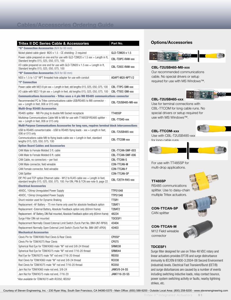
Tr i tex I I ™ In tegra ted Actua to rs 51
Tritex II DC Series Cable & Accessories Part No.
“G” Connection Accessories (N/A for 60 mm)
Nickel plated cable gland- M20 x 1.5 - CE shielding- 2 required GLD-T2M20 x 1.5
Power cable prepared on one end for use with GLD-T2M20 x 1.5 xxx = Length in ft, Standard lengths 015, 025, 050, 075, 100 CBL-TDIPC-RAW-xxx
I/O cable prepared on one end for use with GLD-T2M20 x 1.5 xxx = Length in ft, Standard lengths 015, 025, 050, 075, 100 CBL-T2IOC-RAW-xxx
“N” Connection Accessories (N/A for 60 mm)
M20 x 1.5 to 1/2" NPT threaded hole adapter for use with conduit ADAPT-M20-NPT1/2
“I” Connection
Power cable with M23 8 pin xxx = Length in feet, std lengths 015, 025, 050, 075, 100 CBL-TTIPC-SMI-xxx
I/O cable with M23 19 pin xxx = Length in feet, std lengths 015, 025, 050, 075, 100 CBL-TTIOC-SMI-xxx
Communications Accessories - Tritex uses a 4 pin M8 RS485 communications connectorRecommended PC to Tritex communications cable-USB/RS485 to M8 connector - xxx = Length in feet, 006 or 015 only CBL-T2USB485-M8-xxx
Multi-Drop RS485 Accessories
RS485 splitter - M8 Pin plug to double M8 Socket receptacle TT485SP
Multidrop Communications Cable M8 to M8 for use with TT485SP/RS485 splitter - xxx = Length in feet, 006 or 015 only CBL-TTDAS-xxx
Multi-Purpose Communications Accessories for long runs, requires terminal block interconnectionsUSB to RS485 convertor/cable - USB to RS485 flying leads - xxx = Length in feet, 006 or 015 only CBL-T2USB485-xxx
Communications cable M8 to flying leads cable xxx = Length in feet, standard lengths 015, 025, 050, 075, 100 CBL-TTCOM-xxx
Option Board Cables and Accessories
CAN Male to Female Molded 3 ft. cable CBL-TTCAN-SMF-003
CAN Male to Female Molded 6 ft. cable CBL-TTCAN-SMF-006
CAN Cable, no connectors – per foot CBL-TTCAN-S
CAN Male connector, field wireable CON-TTCAN-M
CAN Female connector, field wireable CON-TTCAN-F
CAN Splitter CON-TTCAN-SP
EIP, PIO and TCP option Ethernet cable - M12 to RJ45 cable xxx = Length in feet, standard lengths 015, 025, 050, 075, 100. For EIN, PIN & TCN see note 9, page 22. CBL-T2ETH-R45-xxx
Electrical Accessories
48VDC, 10Amp Unregulated Power Supply TTPS1048
48VDC, 15Amp Unregulated Power Supply TTPS1548
Shunt resistor used for Dynamic Braking TTSR1
Replacement -AF Battery - 75 mm frame only used for absolute feedback option T2BAT1
Replacement -External Battery, Absolute Feedback option only (60mm frame) T2BAT2
Replacement -AF Battery, DIN Rail mounted, Absolute Feedback option only (60mm frame) 48224
Surge Filter DIN rail mounted TDCESF1
Replacement Normally Closed External Limit Switch (Turck Part No. BIM-UNT-RP6X) 43404
Replacement Normally Open External Limit Switch (Turck Part No. BIM-UNT-AP6X) 43403
Mechanical Accessories
Clevis Pin for TDM/X060 Rod Clevis & Rear Clevis CP050*
Clevis Pin for TDM/X075 Rear Clevis CP075
Spherical Rod Eye for TDM/X060 male “M” rod end 3/8-24 thread SRM038
Spherical Rod Eye for TDM/X075 male “M” rod end 7/16-20 thread SRM044
Rod Eye for TDM/X075 male “M” rod end 7/16-20 thread RE050
Rod Clevis for TDM/X060 male “M” rod end 3/8-24 thread RC038
Rod Clevis for TDM/X075 male “M” rod end 7/16-20 thread RC050
Jam Nut for TDM/X060 male rod end, 3/8-24 JAM3/8-24-SS
Jam Nut for TDM/X075 male rod end, 7/16-20 JAM7/16-20-SS
*Also available for TDM/X075 with RC050, RE050
Cables/Accessories Ordering Guide
TDCESF1Surge filter designed for use on Tritex 48 VDC rotary and linear actuators provides EFT/B and surge distrurbance immunity to IEC/EN 61800-3:2004-08 Second Environment (industrial) levels. Electrical Fast Transient/Burst (EET/B) and surge disturbances are caused by a number of events including switching inductive loads, relay contact bounce, power system switching activity or faults, nearby lightning strikes, etc.
Options/Accessories
CBL-T2USB485-M8-xxxOur recommended communications cable. No special drivers or setup required for use with MS Windows™.
CBL-T2USB485-xxxUse for terminal connections with CBL-TTCOM for long cable runs. No special drivers or setup required for use with MS Windows™.
CBL-TTCOM-xxxUse with CBL-T2USB485-xxx for long cable runs.
CBL-TTDAS-xxxFor use with TT485SP for multi-drop applications.
TT485SPRS485 communicationssplitter. Use to daisy-chain multiple Tritex actuators.
CON-TTCAN-SPCAN splitter
CON-TTCAN-MM12 Field wireable connector
Courtesy of Steven Engineering, Inc. - 230 Ryan Way, South San Francisco, CA 94080-5370 - Main Office: (650) 588-9200 - Outside Local Area: (800) 258-9200 - www.stevenengineering.com

Copyright 2013, Exlar Corporation 6/13 PN 58361
• Sales Locations
Manufacturing/ Repair Facilities
Copyright 2013, Exlar Corporation 11/13 PN 58361
Curtiss-Wright is an innovative engineering company that provides highly engineered, critical function products, systems and services in the areas of flow control, motion control and metal treatment to the defense, energy and commercial/industrial markets.
USAExlar Corporation—Headquarters18400 West 77th StreetChanhassen, MN 55317TEL: 952.500.6200Toll Free in US and Canada: 855.620.6200General FAX: 952.368.4877Order Only FAX: 952.368.4359www.exlar.com
EuropeExlar Europe GmbHFrankfurter Str. 10765479 RaunheimGermanyTEL: +49 6142 17590-0FAX: +49 6142 17590-69www.exlar.com
Exlar is a business group of Curtiss-Wright Controls. Exlar designs, manufactures and sells linear and rotary motion products worldwide.
our global sales channel is ready to assist you in product selection and support. Please contact us for literature on other product families. Visit www.exlar.com/contacts for a full listing of our sales offices around the world.
Visit tritex2.com For more information


![Tritex II AC · 2014-02-21 · ˘02,;‡p} XP LC› z˝N«&˚łì 3Ò//0Ł。 i EtherNet vw~ˆ M12› s] EtherNet/ IP p}EtherNet/IPÒ, ˆ Rockwell PLC 4v5˝N Tritex II ì Þ˘](https://img.pdfslide.net/doc/110x75/5f407979cdf34224213f84ea/tritex-ii-ac-2014-02-21-02ioeap-xp-lca-zn-30-i.jpg)