Embed Size (px)
Citation preview
7/30/2019 Exp 4-Fuid Mixing
http://slidepdf.com/reader/full/exp-4-fuid-mixing 1/26
1
ABSTRACT/SUMMARY
In this experiment, students were asked to do an experiment with two different
objectives. For the first objective (Experiment 1), students need to determine the flow pattern
when using the different type of impeller with and without the use of baffles. For this objective,
three types of impellers which are turbine, flat blade and propeller are used. Students need to
observe the flow patterns when using the impeller with and without baffles. For the second
objective (Experiment 2), students need to determine the power consumed by a mixer that varies
with speed and the inclusion of baffles. Students need to use hydraulic oil as the fluid to be filled
in the tank. Then, it is needed to determine its power and its rotation speed with and without
baffle. At the end of the Experiment 1, it can be observed that different impellers produce
different type of flow patterns in a baffled tank. In a baffled tank, flat paddle and turbine impeller
produce radial flow pattern whereas screw propeller produces axial flow pattern. In an unbaffled
tank, three types of impellers produced the same flow pattern which is tangential flow pattern.
For Experiment 2, it can be seen that power consumed increases as the speed increases. It also
can be seen that the power consumed in a baffled tank is higher than an unbaffled tank.
7/30/2019 Exp 4-Fuid Mixing
http://slidepdf.com/reader/full/exp-4-fuid-mixing 2/26
2
INTRODUCTION
Mixing of liquid-liquid or solid-liquid system is a complex operation to analyze and
subject to many variables. The choice of mixer for a particular application depends on the degree
of bulk movement or shear mixing required by the process. In order to predict full-scale
requirements, it is usual to model the system and apply dimensional analysis.
Before the dimensional analysis can be used, three conditions must apply:
1. Geometric similarity – This will define the boundary conditions, corresponding
dimensions will have the same ratio.
2. Kinematics similarity – This requires that velocities at corresponding points must have
the same ratio ac those at other corresponding points.
3. Dynamic similarity – This requires that the ratio of forces at corresponding points is
equal to that at other corresponding points.
The modes of flow behavior exist in a mixer laminar and turbulent flow. Both these flow
conditions may be described dimensionally but for turbulent flow its behavior is less significant.
In particular, the power number becomes independent of Reynold’s number beyond a certain
turbulence range. A further factor to consider is surface waves, which are, described by the
Froude number group. In a mixer this phenomena is usually function of the height of the vortex,
which forms. Arm field have developed a model mixer, which can be used to predict the power
consumption of a full-sized mixer by equating Reynold’s number and Froude number. The effect
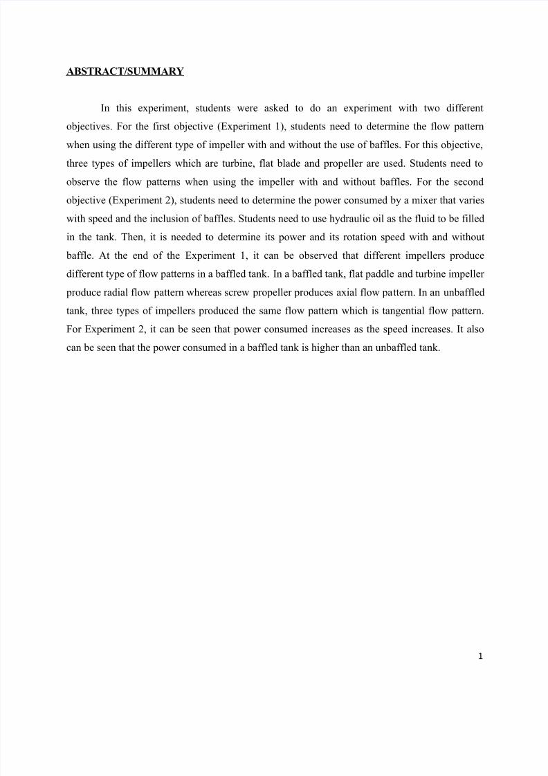
of placing baffles in the mixer vessel is also investigated. In this experiment, we used liquid
mixing apparatus (MB 23) as our operating machine.
7/30/2019 Exp 4-Fuid Mixing
http://slidepdf.com/reader/full/exp-4-fuid-mixing 3/26
3
Figure 1 : Liquid Mixing Apparatus (MB 23)

7/30/2019 Exp 4-Fuid Mixing
http://slidepdf.com/reader/full/exp-4-fuid-mixing 4/26
4
AIMS/OBJECTIVE
Experiment 1 :
The objective of this experiment is to observe the flow patterns that can be achieved by the use
of different impellers with and without the use of baffles.
Experiment 2 :
The objective of this experiment is to show how the power consumed by a mixer varies with
speed, types of impeller and with the inclusion of baffles.
7/30/2019 Exp 4-Fuid Mixing
http://slidepdf.com/reader/full/exp-4-fuid-mixing 5/26
5
THEORY
An impeller is a rotating component of a centrifugal pump which transfer energy from the
motor that drives the pump to the fluid being pumped by accelerating the fluid outwards from the
center of rotation. The velocity achieved by the impeller transfers into pressure when the
outward movement of the fluid is confined by the pump casing. Impeller are usually short
cylinders with an open inlet (called an eye) to accept incoming fluid, vanes to push the fluid
radially, and splined center to accept a driveshaft. There are three types of mixing flow patterns
that are markedly different. The so-called axial-flow turbines actually give a flow coming off the
impeller of approximately 45 degree and therefore have a recirculation pattern coming back into
the impeller at the hub region of the blades.
Axial flow impellers include all impellers in which the blade makes an angle of less than
90 degree with the plane of rotation. They run at the highest efficiency and they have the lowest
NPSH requirement. They require the highest power requirement at shut off, so they are normally
started with the discharge valve open. Axial flow impellers may also be mounted near the bottom
of the cylindrical wall of the vessel.
Radial flow impellers have blades which are parallel to the axis of the drive shaft. The
smaller multiblade ones are known as turbines; larger, slower-speed impeller with two or four
blades are often called paddles. The diameter f a turbines is normally between 0.3 and 0.6 of the
tank diameter. They should be specified for high head and low flow conditions.
As we know, baffles are needed to stop the swirl in a mixing tank. Almost all the impeller
rotate in the clockwise or counter clockwise direction. Without baffles, the tangential velocity
coming from any impeller causes the entire fluid mass to spin. Most common baffles are straight
flat plate of metal that run along the straight side of vertically oriented cylindrical tank or vessel.
For unbaffles tank, there is a tendency for a swirling flow pattern to develop regardless of the type of impeller. A vortex is produced owing to centrifugal force acting on the rotating
liquid. However, there is a limit to the rotational speed that may be used, since one the vortex
reaches the impeller, severe air entrainment may occur. In addition, the swirling mass of liquid
often generates an oscilating surge in the tank, which coupled with the deep vortex may create a
large fluctuating force acting on the mixer shaft.
7/30/2019 Exp 4-Fuid Mixing
http://slidepdf.com/reader/full/exp-4-fuid-mixing 6/26
6
For baffles tank, for vigorous agitation of thin suspensions, the tank is provided with
baffles which flat vertical strips set radially along the tanks wall as shown in figure 1. Four
baffles are almost always adequate. A common baffle width is 1:10 to 1:12 of the tanks diameter.
For Reynolds number greater than 10,000, baffles are commonly used with turbine impellers and
with on-centerline axial-flow impellers.
In the transition region (Reynolds number, from 10 to 10,000), the width of the baffles
may be reduced, often to ½ of standard width. If the circulation pattern is satisfactory when the
tank is unbaffled but a vortex creates a problem, partial length baffles may be used. These are
standard width and extend downward from the surface into about1/3 of the liquid volume.
In the region of laminar flow (NRe< 10), the same power is consumed by the impeller
whether baffles are present or not, and they are seldom required. The flow pattern may be
affected by the baffles but not always advantageously. When they are need, the baffles are
usually placed one or two widths radially, to allow fluid to circulate behind them and at same
time produce some axial deflection of flow.
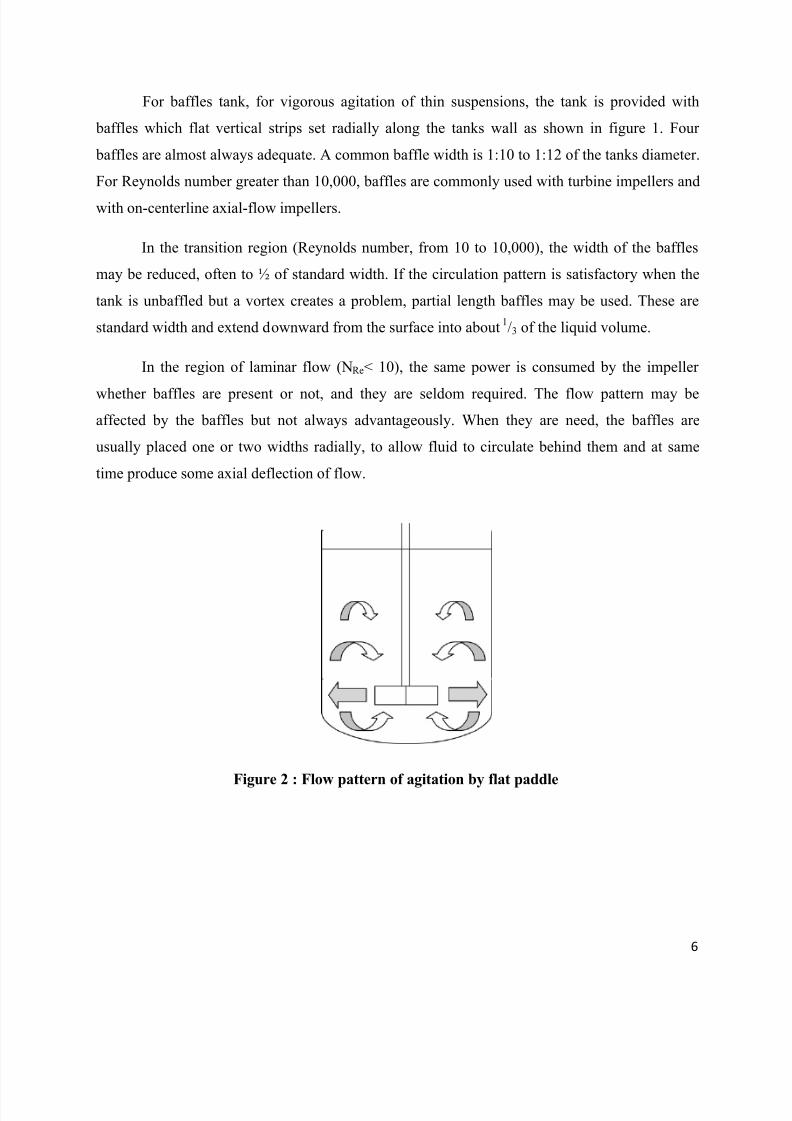
Figure 2 : Flow pattern of agitation by flat paddle
7/30/2019 Exp 4-Fuid Mixing
http://slidepdf.com/reader/full/exp-4-fuid-mixing 7/26
7
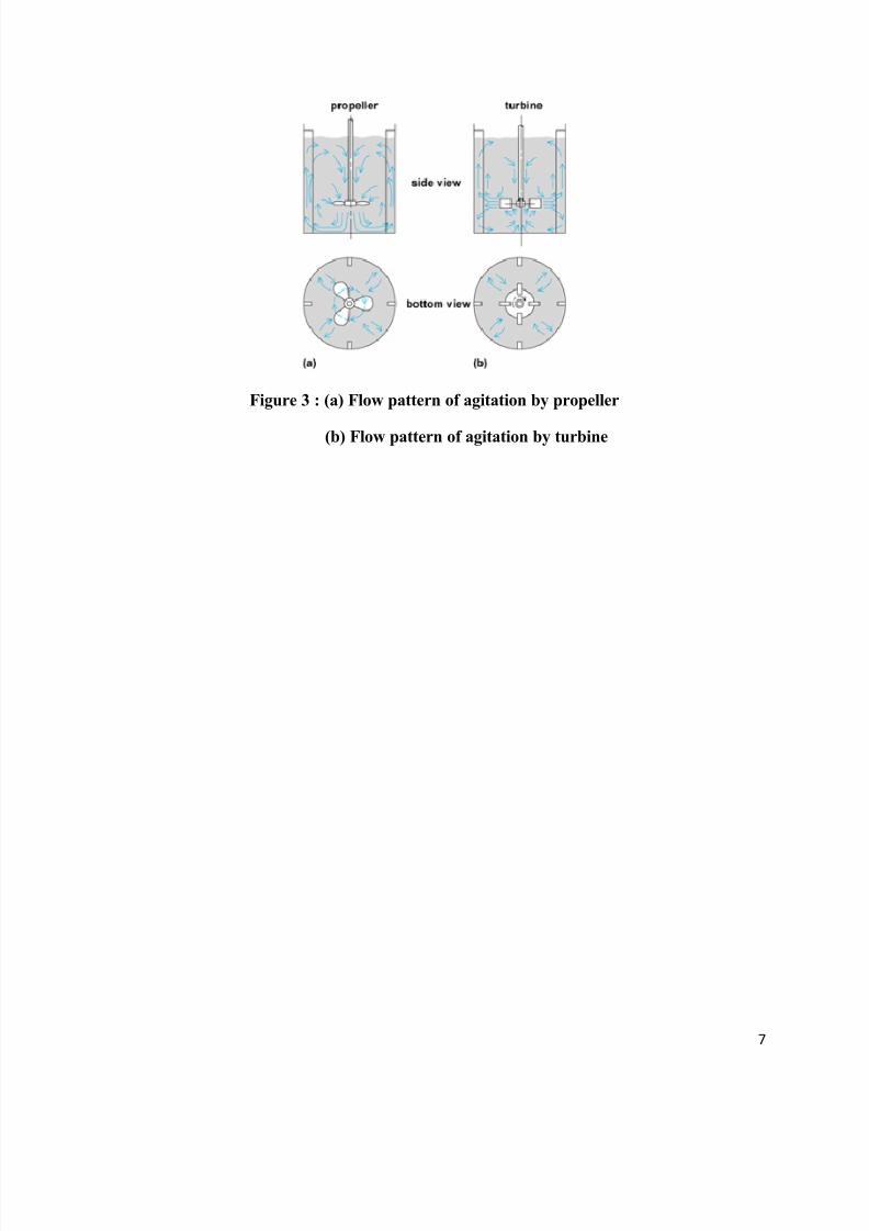
Figure 3 : (a) Flow pattern of agitation by propeller
(b) Flow pattern of agitation by turbine
7/30/2019 Exp 4-Fuid Mixing
http://slidepdf.com/reader/full/exp-4-fuid-mixing 8/26
8
APPARATUS & MATERIALS
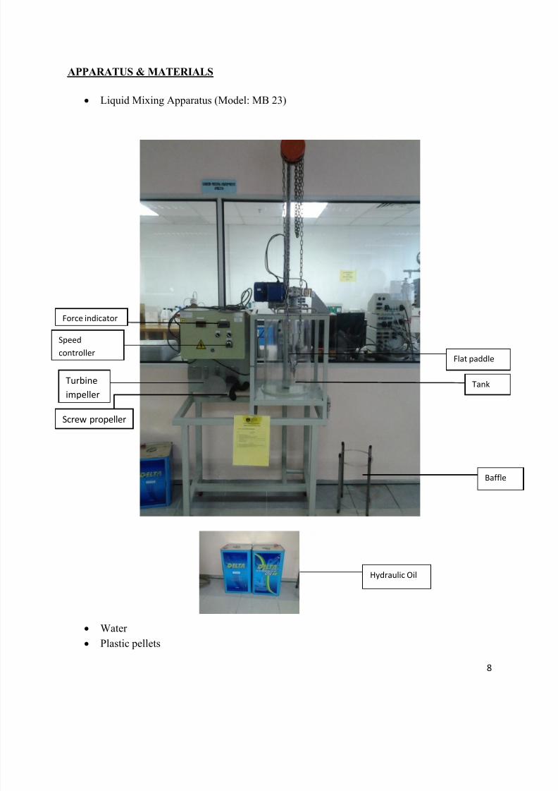
Liquid Mixing Apparatus (Model: MB 23)
Water
Plastic pellets
Flat paddle
Tank
Baffle
Screw propeller
Force indicator
Turbine
impeller
Speed
controller
Hydraulic Oil
7/30/2019 Exp 4-Fuid Mixing
http://slidepdf.com/reader/full/exp-4-fuid-mixing 9/26
9
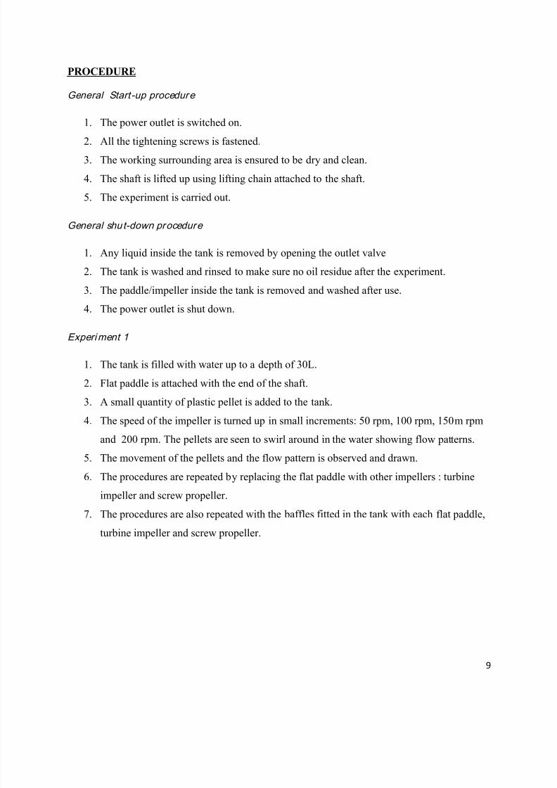
PROCEDURE
General Start-up procedure
1. The power outlet is switched on.
2. All the tightening screws is fastened.
3. The working surrounding area is ensured to be dry and clean.
4. The shaft is lifted up using lifting chain attached to the shaft.
5. The experiment is carried out.
General shut-down procedure
1. Any liquid inside the tank is removed by opening the outlet valve
2.
The tank is washed and rinsed to make sure no oil residue after the experiment.3. The paddle/impeller inside the tank is removed and washed after use.
4. The power outlet is shut down.
Experiment 1
1. The tank is filled with water up to a depth of 30L.
2. Flat paddle is attached with the end of the shaft.
3. A small quantity of plastic pellet is added to the tank.
4. The speed of the impeller is turned up in small increments: 50 rpm, 100 rpm, 150m rpm
and 200 rpm. The pellets are seen to swirl around in the water showing flow patterns.
5. The movement of the pellets and the flow pattern is observed and drawn.
6. The procedures are repeated by replacing the flat paddle with other impellers : turbine
impeller and screw propeller.
7. The procedures are also repeated with the baffles fitted in the tank with each flat paddle,
turbine impeller and screw propeller.

7/30/2019 Exp 4-Fuid Mixing
http://slidepdf.com/reader/full/exp-4-fuid-mixing 10/26
10
Experiment 2
1. The tank filled with hydraulic oil up to a depth of 30 L
2. Flat paddle is attached with the end of the shaft.
3. The speed of the impeller is turned up to 50 rpm and the reading of force is recorded.
4. The speed is then turned up to 100 rpm, 150 rpm and 200 rpm with the force recorded at
the respective speed.
5. Step 3-4 is repeated with the baffles fitted in the tank.
6. The power consumed for each of the speed is calculated.

7/30/2019 Exp 4-Fuid Mixing
http://slidepdf.com/reader/full/exp-4-fuid-mixing 11/26
11
RESULTS
EXPERIMENT 1: Observation of the flow patterns
WITH BAFFLES
Flat Paddle Screw Propeller Turbine Blade
WITHOUT BAFFLES
Flat Paddle Screw Propeller Turbine Blade
Notes : All of the flow patterns drawn are viewed from bottom view.
7/30/2019 Exp 4-Fuid Mixing
http://slidepdf.com/reader/full/exp-4-fuid-mixing 12/26
12
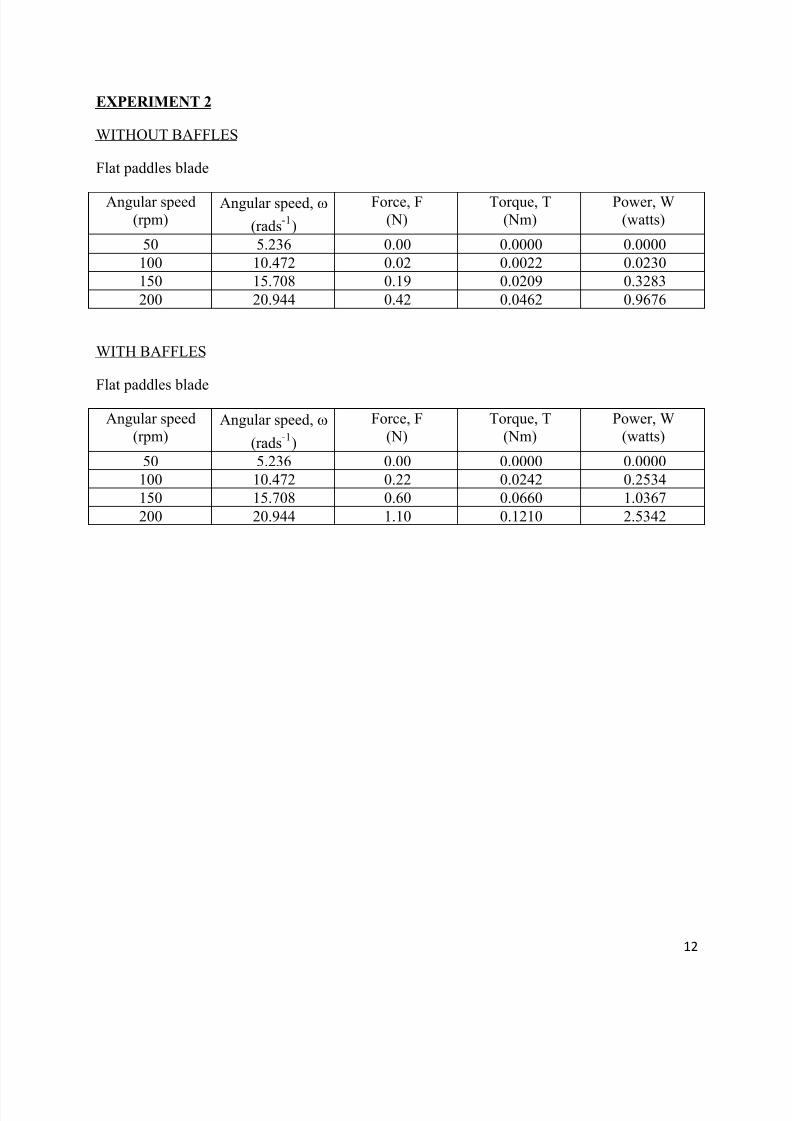
EXPERIMENT 2
WITHOUT BAFFLES
Flat paddles blade
Angular speed(rpm)
Angular speed,
(rads-
Force, F(N)
Torque, T(Nm)
Power, W(watts)
50 5.236 0.00 0.0000 0.0000
100 10.472 0.02 0.0022 0.0230
150 15.708 0.19 0.0209 0.3283
200 20.944 0.42 0.0462 0.9676
WITH BAFFLES
Flat paddles blade
Angular speed
(rpm)Angular speed,
(rads-
Force, F
(N)
Torque, T
(Nm)
Power, W
(watts)
50 5.236 0.00 0.0000 0.0000
100 10.472 0.22 0.0242 0.2534
150 15.708 0.60 0.0660 1.0367
200 20.944 1.10 0.1210 2.5342
7/30/2019 Exp 4-Fuid Mixing
http://slidepdf.com/reader/full/exp-4-fuid-mixing 13/26
13
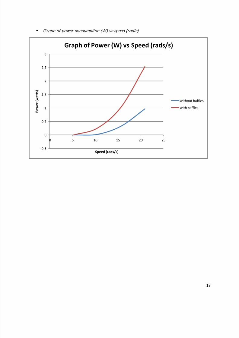
Graph of power consumption (W) vs speed (rad/s)
-0.5
0
0.5
1
1.5
2
2.5
3
0 5 10 15 20 25
P o w e r ( w a t t s )
Speed (rads/s)
Graph of Power (W) vs Speed (rads/s)
without baffles
with baffles
7/30/2019 Exp 4-Fuid Mixing
http://slidepdf.com/reader/full/exp-4-fuid-mixing 14/26
14
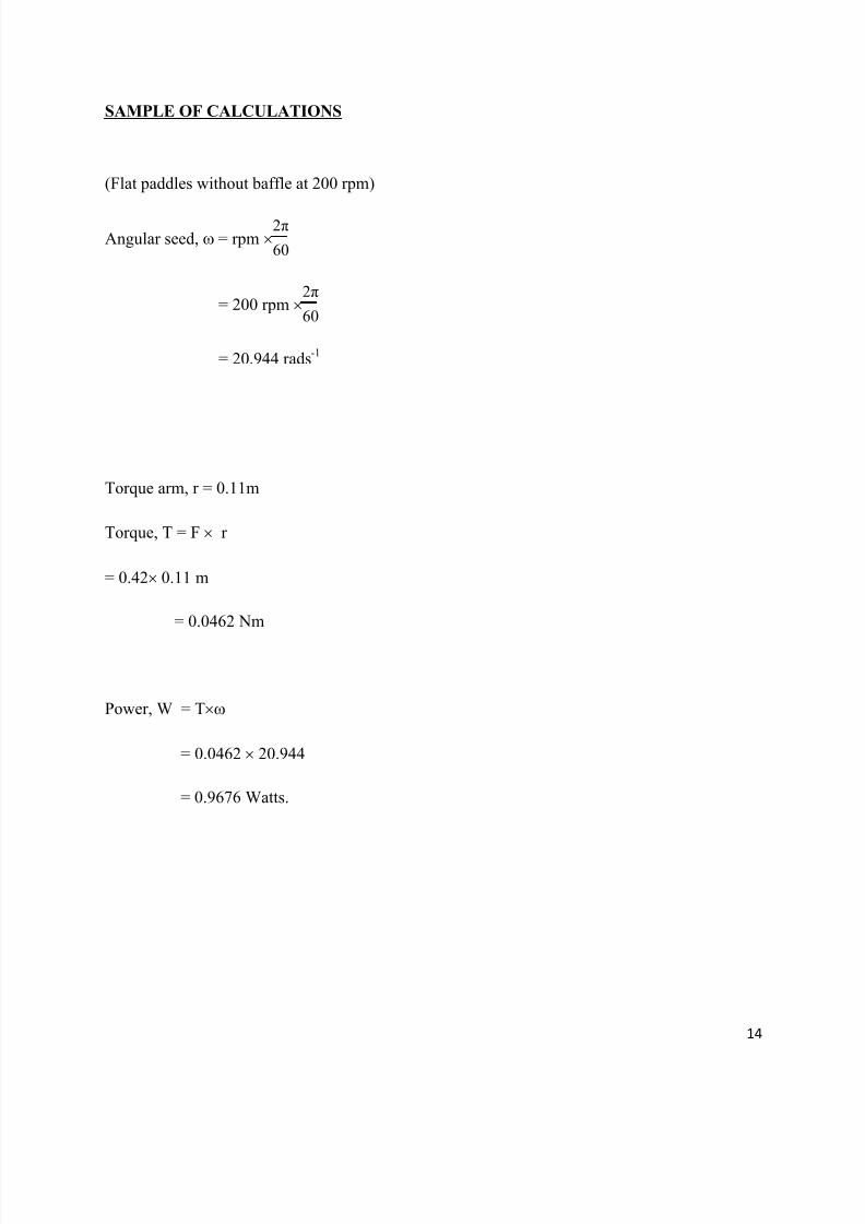
SAMPLE OF CALCULATIONS
(Flat paddles without baffle at 200 rpm)
Angular seed, = rpm
= 200 rpm
= 20.944 rads-1
Torque arm, r = 0.11m
Torque, T = F r
= 0.42 0.11 m
= 0.0462 Nm
Power, W = T
= 0.0462 20.944
= 0.9676 Watts.
7/30/2019 Exp 4-Fuid Mixing
http://slidepdf.com/reader/full/exp-4-fuid-mixing 15/26
15
DISCUSSIONS
This experiment is divided into two parts: Experiment 1 and Experiment 2 with two
different objectives. Experiment 1 is conducted to observe the flow patterns that be achieved by
the use of different impellers with and without the use of baffles. Whereas Experiment 2 is
conducted to show how the power consumed by a mixer varies with speed and the inclusion of
baffle. To achieve these objectives, liquid mixing apparatus (model:MB23) is used.
In Experiment 1, the flow patterns of water with the aid of the plastic pellets are
observed. Six set of flow patterns are drawn with the use of 3 different impellers with and
without the baffle. These impellers are actually the agitator for mixing the substances. Agitation
and swirling are the method for combining the compounds. Therefore, flow patterns of the water
depend on the type of impeller/agitator used. There are three different types of flow patterns
which are axial, radial and tangential.
Based on the flow patterns drawn, it can be observed that all three types of impellers
without the inclusion baffles produced the same flow pattern. That is, a circular and rotary
motion. Another observation seen during the experiment is the production of the deep vortex in
an unbaffled tank. These characteristics can be related to the tangential flow pattern. Thus,
tangential flow patterns are produced in an unbaffled tank. Tangential flow patterns offer very
little mixing because of the small velocity gradients.
With the inclusion of baffle, the use of flat paddle and turbine blade as the impeller
produced the same flow pattern. At the corners of the tank near the baffle, it can be seen that the
pellets are flowing parallel to the impeller and then towards the tank wall. The flow is observed
to have actually split into two streams which are then continuing flowing along the tank wall and
back to the impeller. The flow pattern produced is radial. This makes the flat paddle and turbine
the radial-flow impellers.
7/30/2019 Exp 4-Fuid Mixing
http://slidepdf.com/reader/full/exp-4-fuid-mixing 16/26
7/30/2019 Exp 4-Fuid Mixing
http://slidepdf.com/reader/full/exp-4-fuid-mixing 17/26
17
CONCLUSIONS
From the observation in experiment 1, it can be concluded that different impellers
produce different type of flow patterns in a baffled tank. In a baffled tank, Flat paddle and
turbine impeller produced radial flow pattern whereas screw propeller produced axial flow
pattern. For a tank without the inclusion of baffle, it can be concluded that all three type of
impellers produced the same flow pattern which is tangential flow pattern. Based on the results
and the graph obtained for Experiment 2, it can be seen that power consumed increases as the
speed increases. It also can be seen that the power consumed in a baffled tank is higher than an
unbaffled tank.
Even though the objective of the experiment is reached, a lot of improvements must be
considered to overcome the experimental problems and obtain the best results throughout this
experiment. For example, ensure that the equipment is in a proper operating good condition as
the unit has been used at many times and the tank should be cleaned thoroughly especially after
conducting the experiment to prevent the oil and water from mixing. It is also necessary to make
sure the balance is operating in a good condition to avoid experiencing problems with the
reading of the force balance. Moreover, ensure that the eyes are perpendicular to the scale of the
tank during refill the tank with water to avoid parallax error and different color plastic pellet
must be used to detect flow patterns easily. Also, two tanks should be provided by the laboratory
so that the water and oil can be prevented from mixing.
7/30/2019 Exp 4-Fuid Mixing
http://slidepdf.com/reader/full/exp-4-fuid-mixing 18/26
18
RECOMMENDATIONS
Due to the experiment that has been done, there are few recommendations that should be
considered to get the best results needed throughout in this experiment. First and the foremost,
ensure that the equipment is in a proper operating good condition. It is suggested to repair and
always do some maintenance for this equipment when the unit has been used at many times.
Since this experiment should be done with water source and coagulant or oil as a fluid,
the tank should be cleaned thoroughly especially after conducting the experiment with oil. This
is because to prevent the high concentration of coagulant or oil to be attached the wall of the
tank. This is also to prevent the oil and water from mixing. Therefore, the tank can be used again
when conducting the next experiment.
Other than that, it is necessary to make sure the balance is operating in a good condition.
If the balance is not operating very well, it will affect the reading for the force balance regarding
to each speed of impellers. It is not the right way to measure the force by operating the tension
spring manually, it is much better to use the tension spring that operated by computer itself.
Indirectly, the accurate readings can be obtained as the best results needed.
Furthermore, ensure that the eyes must be perpendicular to the scale of the tank during
refill the tank with water to avoid parallax error. Besides that, always make sure that the water
does not spill over the side of the tank by increasing the speed too much. In addition, several
different colors of plastic pallets can be used, so the flow pattern can be detected easily. Because
of that, the movement of the plastic pellets can be seen clearly.
Last but not least, it is much better to suggest that two tanks should be provided by the
laboratory. One of them is for water and the remaining one for coagulant or oil. This is to ensure
that the water and oil can be prevented from mixing. The mixture between water and oil can be
happened if only one tank provided and used the same tank to conduct the experiment. This willaffect the data as well as inaccurate readings when conducting this experiment.

7/30/2019 Exp 4-Fuid Mixing
http://slidepdf.com/reader/full/exp-4-fuid-mixing 19/26
19
REFERENCES
[1] Douglas J.F Fluid mechanics fourth edition, Prentice Hall 2004
[] Perry’s Chemical Engineer Handbook, 8th
Edition, Don W. Green, Robert H. Perry,18-6 –
18-13.
[3] Frank M.W, Fluid Mechanics ninth edition, McGraw-Hill.2005
[4] www.sciencedirect.com
7/30/2019 Exp 4-Fuid Mixing
http://slidepdf.com/reader/full/exp-4-fuid-mixing 20/26
20
APPENDICES
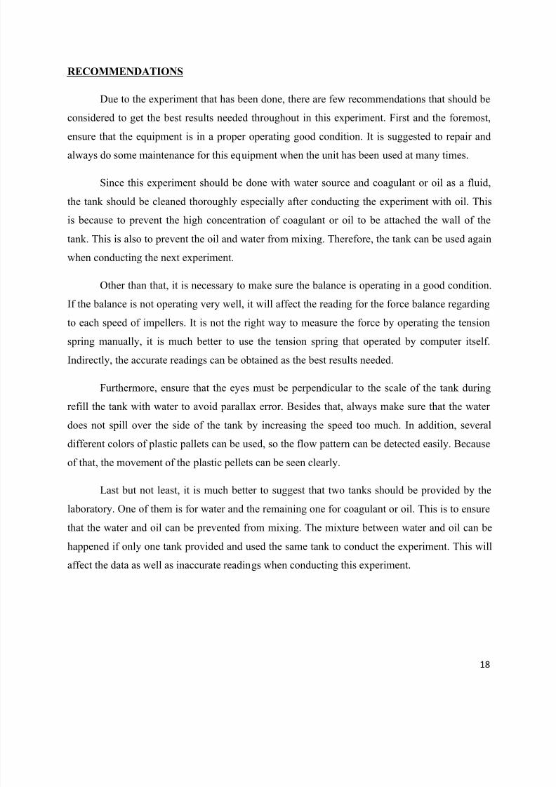
1. Liquid Mixing Apparatus
Liquid Mixing Equipment (Model : MB23)
Control Panel
7/30/2019 Exp 4-Fuid Mixing
http://slidepdf.com/reader/full/exp-4-fuid-mixing 21/26
21
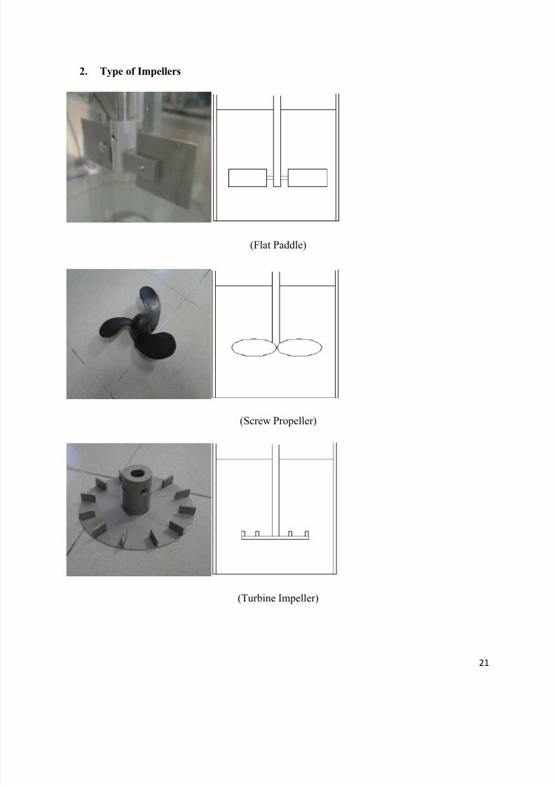
2. Type of Impellers
(Flat Paddle)
(Screw Propeller)
(Turbine Impeller)

7/30/2019 Exp 4-Fuid Mixing
http://slidepdf.com/reader/full/exp-4-fuid-mixing 22/26
22
Baffle Hydraulic Oil

7/30/2019 Exp 4-Fuid Mixing
http://slidepdf.com/reader/full/exp-4-fuid-mixing 23/26
23

7/30/2019 Exp 4-Fuid Mixing
http://slidepdf.com/reader/full/exp-4-fuid-mixing 24/26
24

7/30/2019 Exp 4-Fuid Mixing
http://slidepdf.com/reader/full/exp-4-fuid-mixing 25/26
25

7/30/2019 Exp 4-Fuid Mixing
http://slidepdf.com/reader/full/exp-4-fuid-mixing 26/26


![Application Package OF GOOD MORAL CHARACTER C.P.R. CARD [Mandatory] STATEMENT OF COMMITMENT INFECTION CONTROL [Signed] DESCRIPTION NUMBER EXP. DATE EXP. DATE EXP. DATE EXP. DATE EXP](https://img.pdfslide.net/doc/110x75/5abd9eef7f8b9a3a428bfa58/application-of-good-moral-character-cpr-card-mandatory-statement-of-commitment.jpg)


![Roteiros Exp Quim Analitica Exp IISem_2015 [593260]](https://img.pdfslide.net/doc/110x75/563dbaf4550346aa9aa90789/roteiros-exp-quim-analitica-exp-iisem2015-593260.jpg)