Embed Size (px)
Citation preview
International Journal of Infrared and Millimeter Waves, Vol. 14, No. 4, 1993
Experimental Analysis Of Metal Coated Dielectric Waveguides*
C. S. Yeh, N. Urimindi, Jin Liu, G. A. Evans and J. K. Butler Department of Electrical Engineering
Southern Methodist University, Dallas, Texas 75275
Received February 20, 1992
Abstract
This paper concerns the experimental characteristics of metal coated dielectric waveguides with a rectangular surface corrugation. Waveguide are designed to operate at a second Bragg frequency of 90 GHz. The period, height and the duty cycle of a rectangular grating were calculated using the chosen frequency. A metallic layer of alu- minum is sputtered on one side of the slab waveguide. The purpose of the metallic layer is to simulate a layer of high density plasma on the surface of the waveguide similar to that obtained by optical excitation of semiconductor structures. Experiments were performed to examine the far field radiation pattern, attenuation constant and the dispersion relation. Due to the presence of the plasma layer there will be an angu- lar shift in the far field radiation pattern. We have observed angular shifts of about 20 ~ in the radiation pattern of the waveguide before and after coating. Measurements are made in the frequency range of 88-95 GHz. This waveguide structure can be used to design an electronically steerable antenna and an electronic phase shifter operating in the mil- limeter-wave frequency band.
Introduction
Dielectric waveguides with periodic corrugations have been used in many devices for integrated optics such as filters, beam-couplers, phase shifters, distributed Bragg reflectors (DBR), distributed feedback lasers (DFB), nonlinear generation of second harmonics and beam steering devices. The operation of devices containing a periodic dielec- tric grating depends on the properties of the electromagnetic fields guided by the structure. Waves that are supported by an open periodic structure appear either as surface waves, which travel parallel to the structure, or as leaky waves, which are guided .by the structure but radi- ate or leak energy continuously into the exterior region. Both types of waves appear as characteristic solution of the boundary-value problem prescribed by the waveguide configuration.
Periodic structures are characterized by: 1) Eigenmodes that con- sist of an infinite number of space harmonics, 2) stop bands, (thus only
* Supported in part by the An'ny Research Office.
0195-927 I193/~00-G~85507.~)/0 0 1993 Plenum Publishing C~orat/oo
886 Yeh a a/.
certain wavelength waves can propagate in the structure) and 3) radia- tion. The propagation characteristics of a millimeter-wave in a dielec- tric waveguide with a plasma layer has been of significant interest. With the a plasma layer on the corrugated dielectric waveguide a shift in the propagation constant was observed and the radiation pattern shifts accordingly from the one without a plasma layer. After a certain value of the plasma density, the phase shift is more or less a constant. We can simulate high plasma densities by using a metallic layer and still make the waveguide to work as a phase shifter. This task of simulating plasma was carried in the present analysis.
Fabrication of the Grating Structure
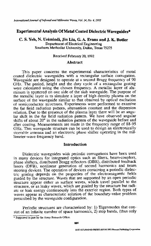
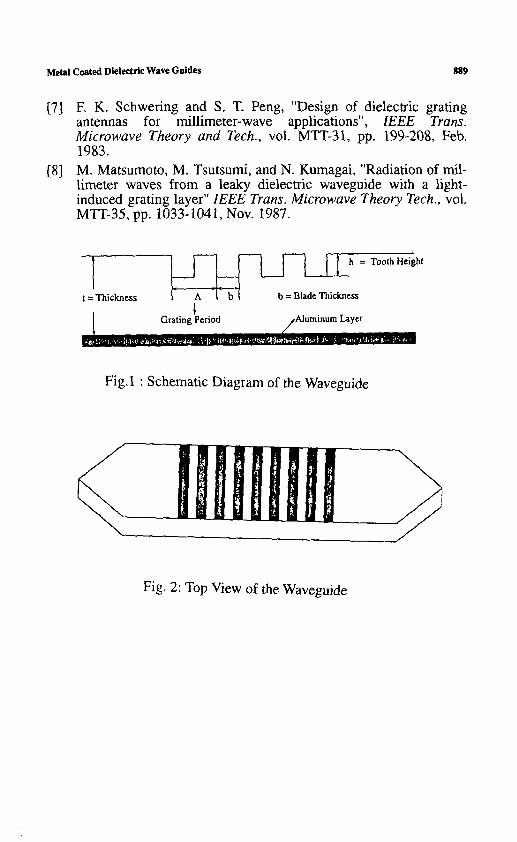
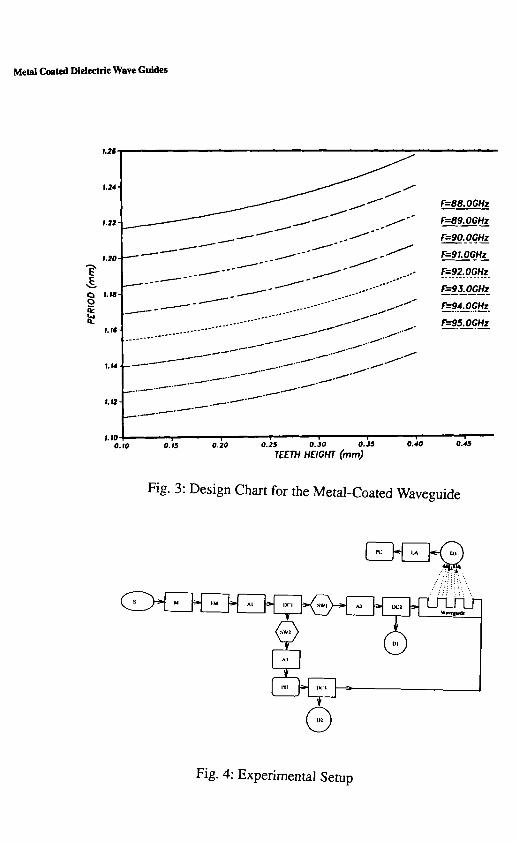
The millimeter-wave source used in the experiment is an IMPA'I~ diode oscillator operating in the frequency range of 88-95 GHz. We chose a frequency at the second Bragg condition which falls in the above frequency range. The next step is to fix the period of the waveguide for the chosen frequency. Obtain the corresponding tooth height for the specified period at that frequency from Fig.3, which shows the relationship between the tooth height and the period of the grating for different frequencies. Surface corrugations are made by a precision wafering machine. This machine consists of a rotating dia- mond wheel whose shaft is connected to a motor assembly. We have fabricated two waveguides in the present work. Fig.1 shows the schematic diagram of the waveguide with grating.An aluminum foil (16 /2m) is pasted on the flat side of the first waveguide after making corru- gations. The flat side of the second waveguide is sputtered with an alu- minum layer (1/tm) after making corrugations. Both the ends of t h e waveguide are tapered at an angle of 4 for better coupling between metallic and dielectric waveguides. The top view of the waveguide is shown in Fig.2.
Experimental Set-Up
The detailed experimental setup is shown in Fig.4. The functional blocks of the setup are as follows. S: Tunable IMPATT oscillator.
M: Ferrite modulator: Used to chop the incident wave for the purpose of lock-in amplifier measurement.
FM: Precision frequency meter.
A1, A2, A3: (Variable attenuators): A1 is used to regulate the mm-wave power entering the system. A2 and A3 are used to regulate the power incident on either side of the dielectric waveguide.
Metal Ceated Dielectric Wave Guides
DC1, DC2, DC3: (Directional couplers): DC1 is a 3 dB coupler used to divide the power into the two branches of the experimental setup. DC2 and DC3 are 10 dB couplers used to monitor the incident power level.
SW1, SW2: (Manual waveguide switches): In the "open" position all the power is dissipated in a matched terminator.
PH: (Rotary-vane phase shifter): This is used to control the phase rela- tionship between the two incident waves.
D1, D2, D3: (Flat broadband detectors): D1 and D2 are used to monitor the incident power and D3 is used to detect the far-field radiation. Lock-in amplifiers are used to amplify the signal from the detector. The output from the lock-in amplifier is directed to personal computer through the HP-IB.
MA: Motor assembly and linear potentiometer are used to rotate D3 and to measure the angle with the help of a computer.
AS: Millimeter wave absorber used for attenuation constant measure- ment.
Results
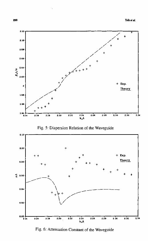
Dispersion curve for the waveguide with an aluminum layer on the flat side was obtained over a frequency band of 88-95 GHz. This is because of better availability of components designed to operate at the lower frequencies and greater ease in fabricating dielectric waveguides with dimensions on the order of few millimeters. A similar waveguide structure with a sputtered layer of aluminum on the fiat side was also investigated in the laboratory. As is evident from Fig.5, the agreement between experiment and theory is good for the dielectric guide.
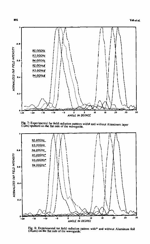
The variation of attenuation with frequency is shown in Fig.6. Theoretically computed values of the attenuation constant are also included in the same figure for comparison. The experimentally observed values of the attenuation are found to be close to theory. A slight deviation from the theory may be accounted for error during fab- rication. Fig.7 shows the experimental far field radiation pattern before and after sputtering a layer of aluminum (1/2m) on the fiat side of the waveguide at different frequencies. We have noticed an angular shift of about 20 ~ in the radiation pattern of the waveguide with and without the metallic layer. Radiation measurements are made at 92, 93, 94 GHz. In addition to the main lobe, some side lobes are also observed. This may be due to the presence of the reflected power from the other end of the metallic waveguide. The experiment is repeated for the waveguide with
888 Yeh ~ a/.
an aluminum foil (16/tm) pasted on the flat side. The radiation pattern is shown in Fig.8 and is very s imilar to the one shown in Fig.7. This indicates the repeatability of the results for different waveguide sam- ples.
Conclusion
Results of experimental analysis of metal coated dielectric waveguides used in millimeter-wave systems have been presented. The analysis yields parametric dependencies that should prove useful in the understanding and design of electronic phase shifters. The data are also essential for the design of millimeter-wave beam steering devices.The presented results shows that these waveguides can be used as mil- limeter-wave antennas. High density plasma was simulated by deposit- ing an aluminum layer on the flat-side of the waveguide. The angular shift in the radiation pattern before and after coating the metallic layer was measured. Similar results for the waveguide with a sputtered layer of aluminum was obtained. Typical value of the angular shift observed was 20 ~ which is significant enough to build an electronic phase shifter to be operated at millimeter-wave frequencies. The dispersion relation and the attenuation constant were also measured in the frequency range of present interest.
References
[1] S. T. Peng, T. Tamir and H. L. Bertoni, " Theory of periodic dielectric waveguides," IEEE Trans. Microwave Theory and Tech., vol. MTI'-23, pp. 123-133, Jan. 1975.
[2] W.V. McLevige, T. Itoh and R. Mittra, "New waveguide struc- tures for millimeter-wave and optical integrated circuits", IEEE Trans. Microwave Theory and Tech., vol. MTI'-23, pp. 788-794, Oct. 1975.
[3] T. Itoh, "Application of gratings in a dielectric waveguide for leaky-wave antennas and band-reject filters," IEEE Trans. Microwave Theory and Tech., vol. MTT-25, pp. 1134-1138, Dec. 1977.
[4] A. P. Defonzo, "Optically controllable millimeter wave phase shifter", Appl. Phys. Lett., vol. 35, pp. 575-577, Oct. 1979.
[5] C .H. Lee, S. Mak, and A. P. Defonzo, "Optical control of mil- limeter-wave propagation in dielectric waveguides", IEEE J. Quantum Electron., vol. QE-16, pp. 277-288, Mar. 1980.
[6] K. Ogusu, "Propagation properties of a planar dielectric waveguide with periodic metallic strips", IEEE trans. Microwave Theory and Tech., vol. MTI'-29, pp. 16-21, Jan. 1981.
Metal Coated Dielectric Wave Guides 889
[7] E K. Schwering and S. T. Peng, "Design of dielectric grating antennas for millimeter-wave applications", IEEE Trans. Microwave Theory and Tech., vol. MTT-31, pp. 199-208, Feb. 1983.
[8] M. Matsumoto, M. Tsutsumi, and N. Kumagai, "Radiation of mil- limeter waves from a leaky dielectric waveguide with a light- induced grating layer" IEEE Trans. Microwave Theory Tech., vol. MTT-35, pp. 1033-1041, Nov. 1987.
r I t = Thickness b = Blade Thickness
~Jp,~ Gratlngl Period /Aluminum Layer
Fig.1 : Schematic Diagram of the Waveguide
Fig. 2: Top View of the Waveguide
890 Yeh eta/.
o
2 , 1 2
~'.lO"
2 . 0 6 "
2 . 0 8 "
2.04"
2 . 0 2 "
2-
i . 9 0 "
j . - - r
J J +
J n.90- ~ +
/ +++ %
1.94 z , , 2;e 2;8
/ /+
/ / +
/ / +
/ /
/ + / +
/ /+ + + +
+Y +/ /
§
+
+ Exp.
Theory
k,A 2.50 2.~2
0 . 1 2 -
0.10-
O.OB-
0 . 0 0 -
0.04 "
0 , 0 2 -
0.00 2.14
Fig. 5: Dispersion Relation of the Waveguide
+
+ +
+ + +
+
+ +
\ + + ~ - + f ~
+ +
+ +
-I- + +
+ Exp.
Th__eory
k.A
+ +
2.~2
Fig. 6: Attenuation Constant of the Waveguide
2,34
2.34
Metal Coated Dielectric Wave Guides
+-p
1,21
|~
! ,22-
L20-
f . fB-
..........---- -
f. M -
r . |4-
1.12-
l.lO 0,10
i f / / - "
o ~ 1 7 6 1 7 6 1 7 6 / o t J "
/ . / .... ~
..o+.~176176176176176176176176176176 o+O ~ oO .o, ,~ . ,~ . .~ . . . . . , . .~ - ' ~ . / " ~ S
. . . . . . .~176176176 . . J ~
.~ .~~176 ~ " / / / / / . ~ . o. o...o., o. ,......o -- ~
0;5 o'2o o ~5 o Jo o.;5 o.;o TEETH HEIGHT (ram)
F'=B8. OGHz
1:'=89. 0 GHz
F=90. OGHz
F'=g I. OGHz
F=92. OGHz
F=g 3. 0 G Hz
F=94. OGHz
F=95. OGHz
o.;5
Fig. 3: Design Chart for the Metal-Coated Waveguide
G
Fig. 4: Experimental Setup
NO
RM
AU
ZED
FAR
FIE
LD I
NTE
NS
ITY
N
OR
MA
LIZE
D F
AR F
IELD
IN
TEN
SIT
Y
o
I'o
:'o
"o
t'~
%
o ~,
.. J'~
:'o
~
I'o
%
o ""
Io
:o
o
,o
o o
L ~"
]c
~ :r
r ,o
o
o ~:
., ,o
~olo
,olo
lo
I .-~
.=
~=!=
,olo
. I
, I.C
'. i.z
,z
;z ;~
;~
i.z
I =~
~ =1
1 "~
.,--
i~ .~
;~
i~ ,
~ I~
I
~ .~
1~
: ...
......
.. ~:
----
----
l <
~ z
~ y.
~
-
~ o=
~
....
.'
~ . .
....
....
....
..
~-
L~
~'I
..
....
...
. ~
" I
~."
~ I~,
~ ...... 7
" I
o~
~ ~
~
......
......
...
-~
--
I
~"
,~:~
:-:
-I--
~ ..
..
__.._
~
---:
~--
'---
-~=
-~
I o=
~
..
..
.
~_
..
. ~
~ -
- ~
- " "
T ,.
~ ~
i "


![Optical Interconnect [호환 모드] - High-Speed Circuits & …tera.yonsei.ac.kr/.../lecture/Optical_Interconnect.pdf · · 2012-12-05Optical interconnect based on dielectric waveguides](https://img.pdfslide.net/doc/110x75/5aa0e4367f8b9a67178ee41e/optical-interconnect-high-speed-circuits-tera-interconnect.jpg)


![[1] Dielectric-fibre surface waveguides for optical frequencies](https://img.pdfslide.net/doc/110x75/577cd9b91a28ab9e78a40602/1-dielectric-fibre-surface-waveguides-for-optical-frequencies.jpg)


