Embed Size (px)
Citation preview

15th International Brick and Block Masonry Conference
Florianópolis – Brazil – 2012
EXPERIMENTAL ASSESSMENT OF THE SHEAR RESPONSE OF AUTOCLAVED AERATED CONCRETE (AAC) MASONRY WITH
FLAT TRUSS BED-JOINT REINFORCEMENT
Mandirola, Martina1; Penna, Andrea2; Rota, Maria3; Magenes, Guido4 1 European Centre for Training and Research in Earthquake Engineering, Pavia, [email protected]
2 Assistant Professor, University of Pavia, Department of Structural Mechanics and European Centre for Training and Research in Earthquake Engineering, Pavia, [email protected]
3 PhD, European Centre for Training and Research in Earthquake Engineering, Pavia, [email protected] 4Associate Professor, University of Pavia, Department of Structural Mechanics and European Centre for
Training and Research in Earthquake Engineering, Pavia, [email protected]
Experimental campaigns carried out in the past showed that the presence of flat truss bed-joint reinforcement provides a general improvement to the performance of masonry panels in resisting actions in the horizontal plane. The truss-like elements are effective both in terms of improved resistance and reduction of damage and, therefore, in the enhanced displacement capacity. The limited number of experimental tests available in the literature hardly allows the derivation of quantitative conclusions on the real benefit of the presence of horizontal reinforcement to the seismic performance of a specific masonry type. Such tests are indeed performed on reduced scale prototypes and do not sufficiently cover the possible combinations of slenderness, axial load and boundary conditions. The experimental campaign presented in this work includes a set of in-plane cyclic tests on autoclaved aerated concrete (AAC) masonry panels with thin horizontal and vertical joints filled with glue-mortar, made both in unreinforced and reinforced masonry with flat truss bed-joint reinforcement. The direct comparison of the results, along with specific tests performed on wallettes, allowed to obtain some futher reference on the effectiveness of the horizontal reinforcement on the enhancement of the global seismic performance of AAC masonry buildings.
Keywords: Autoclaved aerated concrete masonry; thin horizontal joint; flat truss bed-joint reinforcement; experimental tests; strength criteria INTRODUCTION Autoclaved Aerated Concrete (AAC) is a mixture of cement, lime, water and sand that expands by adding aluminium powder. The reaction between aluminium, lime and water causes microscopic hydrogen bubbles to form, expanding the concrete to about two times its original volume. After evaporation of the hydrogen, aerated concrete is cut to size and form and it is transported to a large autoclave where, under physically controlled conditions (temperature and pressure), the curing process is completed. The result is a non-organic, airtight, non-combustible, fire-resisting material characterised by its fine cellular structure, with air pores ranging from 0.1 to 2 mm.

15th International Brick and Block Masonry Conference
Florianópolis – Brazil – 2012
The truss type reinforcement used in the experimental campaign presented in this paper is basically made of two parallel galvanised steel bars or steel thin plates connected by steel wires welded to the parallel bars in a truss-like fashion (see Figure 1).
hc
filled head-joint
flat truss bed-joint reinforcement
thin layer glue-mortar
AAC units
Figure 1. Truss type reinforcement placed in the bed-joint of a masonry wall (left); truss type reinforcement with welded joints (right).
In physical terms, the main advantages of truss reinforcement in horizontally reinforced masonry (HRM) can be enumerated as follows:
• The truss-like element provides lateral confinement to the masonry bed-joint across its width (wall thickness).
• The welded connections provide a considerable degree of anchorage, which is comparable to that offered by anchoring hooks in normal reinforcement bars.
• The presence of horizontal reinforcement is known to confer increased in-plane deformation and ductility capacity to the HRM wall.
• The reinforcement can provide resistance to out-of-plane horizontal bending of the masonry wall.
• Bed-joint thickness is considerably contained. When special mortars are used to reduce joint thickness, the use of flat truss reinforcement is advantageous because it does not significantly increase the joint thickness.
As reported in Penna et al. (2010), several literature works studied the effectiveness of different types of bed-joint reinforcement in masonry walls, either along with vertical steel (e.g. Priestley and Bridgeman, 1974; Schultz et al., 1998; Mosele et al., 2009) or within confined masonry walls (e.g. Ganz and Thürlimann, 1984; Aguilar et al.,1996; Alcocer and Zepeda, 1999; Lourenço et al., 2008; Penna et al., 2008). Nevertheless, the amount of data from tests on masonry walls with bed-joint reinforcement only, which is the focus of the present work, is rather limited (e.g. Tomaževič and Žarnić, 1984,1985; Lourenço et al., 2008; Penna et al., 2008; Mosele et al., 2009). Also, most of these tests were carried out on scaled wallettes and only two of these works included specimens with truss-type reinforcement (Lourenço et al., 2008; Penna et al., 2008). In particular, only one of the test specimens of the experimental campaign performed at EUCENTRE in Pavia (Penna et al., 2008) would fall within the scope of the current study (e.g. only truss-type reinforcement in AAC masonry). For the reasons outlined above, the present study aims at investigating in details the effect of flat truss bed-joint reinforcement on the cyclic shear behaviour of AAC masonry walls.

15th International Brick and Block Masonry Conference
Florianópolis – Brazil – 2012
EXPERIMENTAL TEST CAMPAIGN ON LOAD BEARING AAC WALLS An experimental test campaign was performed to assess the in-plane shear behaviour of AAC masonry piers and to investigate the effect of flat truss bed-joint reinforcement. The testing apparatus (shown in Figure 2) consisted in a double fixed system with a constant vertical load applied at the top by servo-controlled hydraulic actuators. The lateral load was applied in terms of increasing displacement using a horizontal actuator. Three cycles for each displacement level were performed.
Figure 2. Scheme (left) and view (right) of the test setup.
The structural solutions adopted include one unreinforced masonry (URM) wall and two horizontally reinforced masonry walls with truss type reinforcement (HRM). All the masonry piers have the same geometry with a length (l), height (h) and thickness (s) of 2.5 m, 2 m and 0.3 m, respectively. Both bed-joints and head-joints were filled with a thin layer of glue mortar. The dimensions of the blocks are 625 x 300 x 250 mm3. The flat truss bed-joint reinforcement is placed in the wall’s height every two courses (50 cm), for a total of four horizontally reinforced layers. A reinforced concrete beam was built at the top of each wall, with the aim of better distributing the applied loads and reproducing a typical constructive detail. The mechanical properties of masonry were measured experimentally by specific tests, performed on blocks, glue mortar, wallettes (see Figure 3) and horizontal reinforcement. The values obtained from the tests for the most relevant parameters are presented in Table 1, where fb and fm are the block and masonry compressive strength in the direction perpendicular to the horizontal mortar layers (measured according to UNI EN 772-1 and UNI EN 1052-1), fvk0 and fvm0 are the characteristic and mean initial shear strength in the absence of compression according to UNI EN 1052-3, ρm is the masonry density, Asw in the area of the cross section of the bed-joint reinforcement and fyk is the steel characteristic yield strength (provided by the producer). The values of the shear modulus G in Table 1 are calculated from Young’s modulus E by assuming the empirical relationship G=0.26E (Costa et al., 2011) and G=0.32E (obtained according to the experimental results), for the unreinforced and reinforced masonry, respectively. Two levels of vertical load were applied: 300 kN (corresponding to an average compression of 0.4 MPa) for the unreinforced wall (RDB01) and one of the horizontally reinforced walls (RDB02), 450 kN (0.6 MPa) for the other reinforced wall (RDB03). These values correspond

15th International Brick and Block Masonry Conference
Florianópolis – Brazil – 2012
to an axial load ratio of 0.15 and 0.23, respectively. Displacements and possible slipping were measured by 23 linear potentiometers installed on the panels. The axial deformation of the horizontal reinforcement was evaluated by strain gauges (4 for RDB02 and 6 for RDB03, respectively) fixed on the truss-like elements.
Figure 3. Tests on AAC masonry wallettes: vertical (left) and diagonal (right) compression tests.
Table 1: Experimental test results on masonry’s components
Masonry type
fb [MPa]
fm [MPa]
fvk0 [MPa]
fvm0 [MPa]
E [MPa]
G [MPa]
ρm [kg/m3]
Asw [mm2]
fyk [MPa]
URM 3.48 2.33 0.17 0.25 1400 364 500 - - HRM 3.48 2.63 0.17 0.25 1400 448 500 24 600
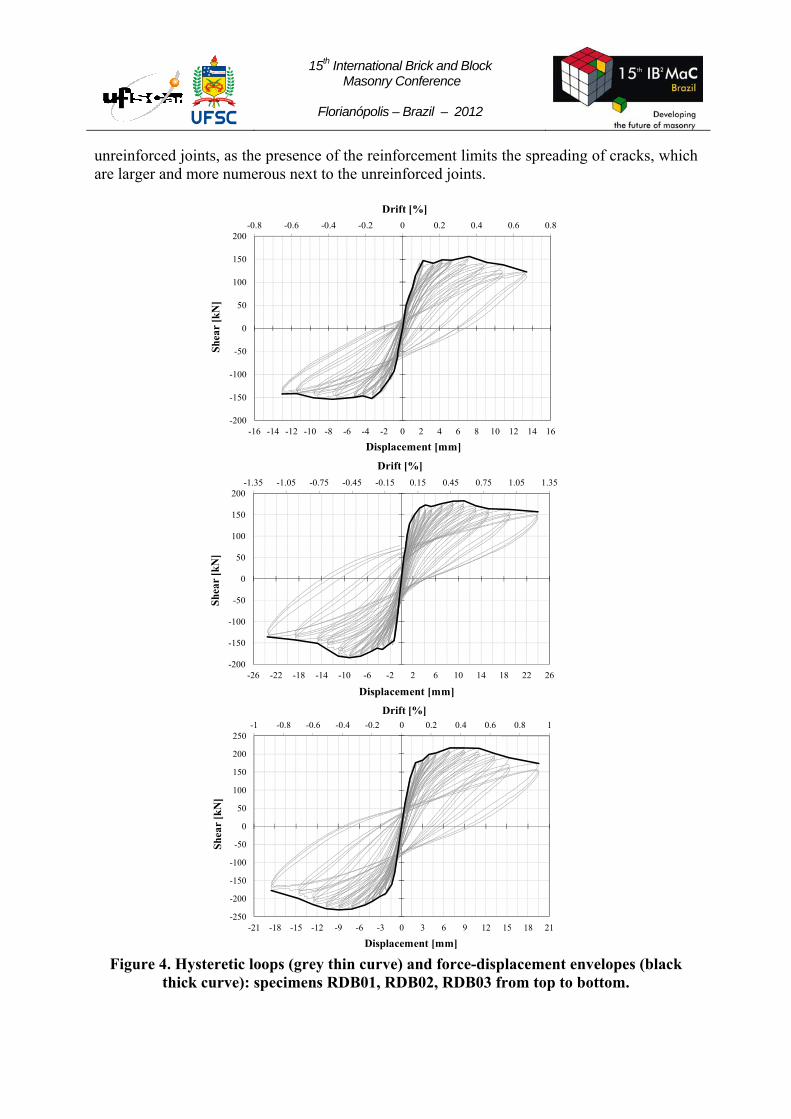
Figure 4 illustrates the horizontal force versus top displacement curves of each specimen. All panels showed a behaviour that can be associated to a typical shear failure mechanism: the diagrams show a response characterized by wide hysteresis loops and degradation of stiffness and strength. Considering the envelope of the cycles, there is a short initial linear trend followed by a descending branch associated with the spread of cross-diagonal cracks. The ultimate and maximum displacement capacity of the specimens were expressed in terms of drift ratios (δu and δmax, respectively, defined as the ratio between the horizontal displacement and the height of the wall). The ultimate drift ratio is defined as that corresponding to a lateral strength decay of 20% (i.e. a 20% decay in the shear-displacement curve); values of δu of about 0.65% and 0.8% were found for the unreinforced and horizontally reinforced panels, respectively. All the tests were actually stopped beyond this limit when the tested specimens showed extensive damage with potential danger to the testing apparatus. This condition occurred for levels of drift equal to 0.7%, 1.25% and 1%, respectively for RDB01, RDB02 and RDB03. As shown in Figure 5, since the early cycles of loading, all the panels showed diagonal cracks mainly affecting the blocks and crossing the centre of the walls. It should be noticed that in the horizontally reinforced specimens, the most significant damage is located in the
15th International Brick and Block Masonry Conference
Florianópolis – Brazil – 2012
unreinforced joints, as the presence of the reinforcement limits the spreading of cracks, which are larger and more numerous next to the unreinforced joints.
-0.8 -0.6 -0.4 -0.2 0 0.2 0.4 0.6 0.8
-200
-150
-100
-50
0
50
100
150
200
-16 -14 -12 -10 -8 -6 -4 -2 0 2 4 6 8 10 12 14 16
Drift [%]Sh
ear [
kN]
Displacement [mm]
-1.35 -1.05 -0.75 -0.45 -0.15 0.15 0.45 0.75 1.05 1.35
-200
-150
-100
-50
0
50
100
150
200
-26 -22 -18 -14 -10 -6 -2 2 6 10 14 18 22 26
Drift [%]
Shea
r [kN
]
Displacement [mm]
-1 -0.8 -0.6 -0.4 -0.2 0 0.2 0.4 0.6 0.8 1
-250
-200
-150
-100
-50
0
50
100
150
200
250
-21 -18 -15 -12 -9 -6 -3 0 3 6 9 12 15 18 21
Drift [%]
Shea
r [kN
]
Displacement [mm] Figure 4. Hysteretic loops (grey thin curve) and force-displacement envelopes (black
thick curve): specimens RDB01, RDB02, RDB03 from top to bottom.
15th International Brick and Block Masonry Conference
Florianópolis – Brazil – 2012
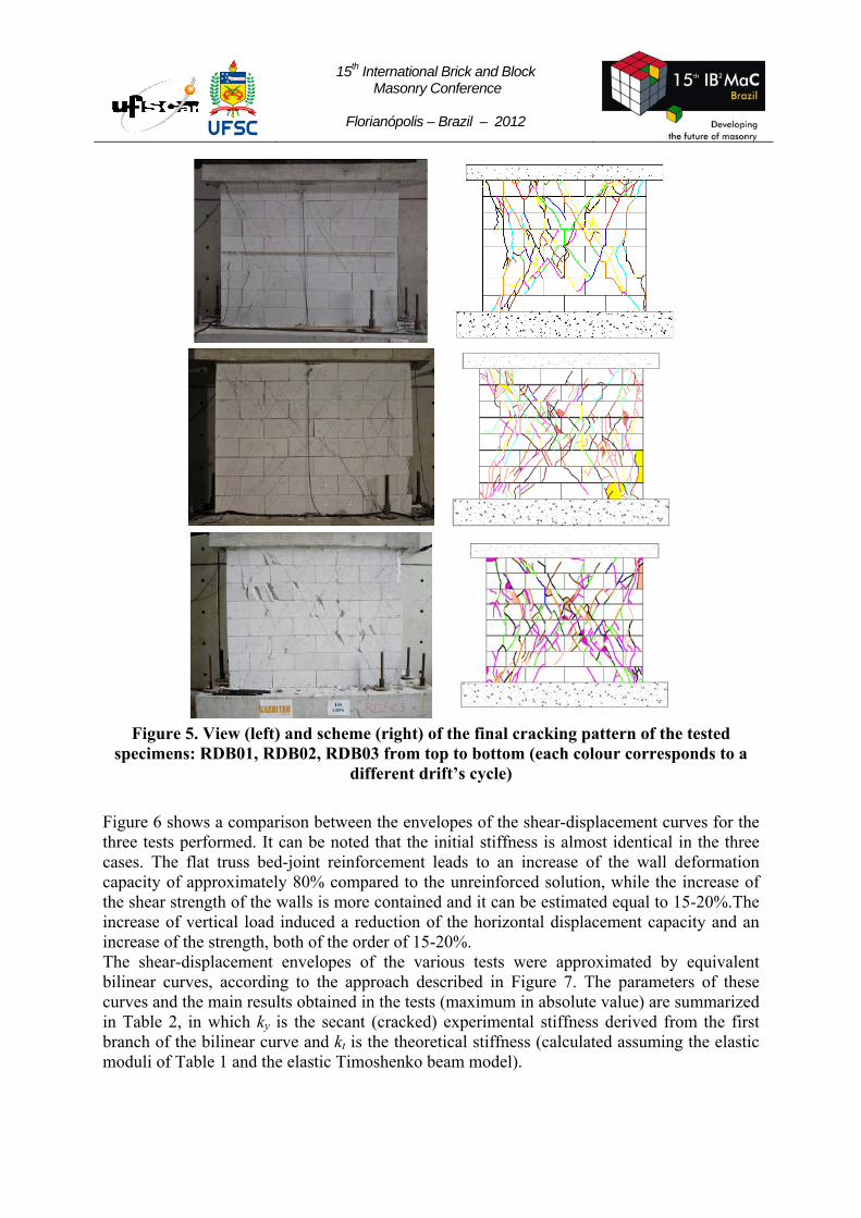
Figure 5. View (left) and scheme (right) of the final cracking pattern of the tested specimens: RDB01, RDB02, RDB03 from top to bottom (each colour corresponds to a
different drift’s cycle) Figure 6 shows a comparison between the envelopes of the shear-displacement curves for the three tests performed. It can be noted that the initial stiffness is almost identical in the three cases. The flat truss bed-joint reinforcement leads to an increase of the wall deformation capacity of approximately 80% compared to the unreinforced solution, while the increase of the shear strength of the walls is more contained and it can be estimated equal to 15-20%.The increase of vertical load induced a reduction of the horizontal displacement capacity and an increase of the strength, both of the order of 15-20%. The shear-displacement envelopes of the various tests were approximated by equivalent bilinear curves, according to the approach described in Figure 7. The parameters of these curves and the main results obtained in the tests (maximum in absolute value) are summarized in Table 2, in which ky is the secant (cracked) experimental stiffness derived from the first branch of the bilinear curve and kt is the theoretical stiffness (calculated assuming the elastic moduli of Table 1 and the elastic Timoshenko beam model).
15th International Brick and Block Masonry Conference
Florianópolis – Brazil – 2012
-1.35 -1.05 -0.75 -0.45 -0.15 0.15 0.45 0.75 1.05 1.35
-250
-200
-150
-100
-50
0
50
100
150
200
250
-26 -22 -18 -14 -10 -6 -2 2 6 10 14 18 22 26
Drift [%]
Shea
r [kN
]
Displacement [mm]
Unreinforced wall_RDB01Horizontally reinforced wall_RDB02
-1.35 -1.05 -0.75 -0.45 -0.15 0.15 0.45 0.75 1.05 1.35
-250
-200
-150
-100
-50
0
50
100
150
200
250
-26 -22 -18 -14 -10 -6 -2 2 6 10 14 18 22 26
Drift [%]
Shea
r [kN
]
Displacement [mm]
Horizontally reinforced wall (N=300kN)_RDB02Horizontally reinforced wall (N=450kN)_RDB03
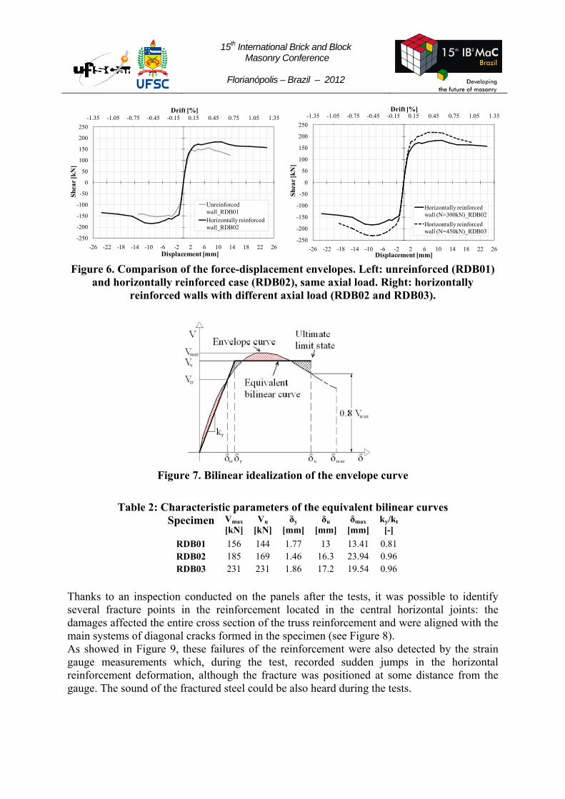
Figure 6. Comparison of the force-displacement envelopes. Left: unreinforced (RDB01) and horizontally reinforced case (RDB02), same axial load. Right: horizontally
reinforced walls with different axial load (RDB02 and RDB03).
Figure 7. Bilinear idealization of the envelope curve
Table 2: Characteristic parameters of the equivalent bilinear curves Specimen Vmax
[kN] Vu
[kN] δy
[mm] δu
[mm] δmax
[mm] ky/kt [-]
RDB01 156 144 1.77 13 13.41 0.81 RDB02 185 169 1.46 16.3 23.94 0.96 RDB03 231 231 1.86 17.2 19.54 0.96
Thanks to an inspection conducted on the panels after the tests, it was possible to identify several fracture points in the reinforcement located in the central horizontal joints: the damages affected the entire cross section of the truss reinforcement and were aligned with the main systems of diagonal cracks formed in the specimen (see Figure 8). As showed in Figure 9, these failures of the reinforcement were also detected by the strain gauge measurements which, during the test, recorded sudden jumps in the horizontal reinforcement deformation, although the fracture was positioned at some distance from the gauge. The sound of the fractured steel could be also heard during the tests.

15th International Brick and Block Masonry Conference
Florianópolis – Brazil – 2012
Figure 8. Pattern (left) and picture (right) of the failures of the horizontal reinforcement in the specimens RDB02 (top) and RDB03 (bottom)
-0.001
-0.0005
0
0.0005
0.001
0.0015
0.002
0.0025
0.003
0 150 300 450 600 750 900 1050 1200
Hor
izon
tal d
efor
mat
ion
time [s]
Strain gauge S1
-0.003
-0.002
-0.001
0
0.001
0.002
0.003
0.004
0 150 300 450 600 750 900 1050 1200
Hor
izon
tal d
efor
mat
ion
time [s]
Strain gauge S6Strain gauge S2
Figure 9. Deformation of the horizontal reinforcement recorded by the strain gauges:
RDB02 (left) and RDB03 (right)
COMMENTS AND CONCLUSIONS The paper presented and discussed the results of cyclic shear-compression tests aimed at characterizing the seismic response of a new system of autoclaved aerated concrete masonry reinforced with only horizontal reinforcement placed in thin horizontal joints filled with glue-mortar. The three panels tested showed a typical shear behaviour with diagonal cracks mainly affecting the blocks and crossing the centre of the panels. In horizontally reinforced specimens, the final extension of cracks was limited if compared to the unreinforced panel and the most significant damage was located in the unreinforced horizontal joints. The presence of horizontal reinforcement (every two masonry courses) allowed an increase of the deformation capacity of the wall with respect to the unreinforced solution. Indeed, the maximum ultimate drift ratio associated with the shear failure mechanism increased,

15th International Brick and Block Masonry Conference
Florianópolis – Brazil – 2012
compared to the values proposed in the literature for unreinforced AAC masonry (Ötes and Löring, 2003; Tanner et al. 2005; Penna et al. 2008; Costa et al. 2011), from 0.3-0.35% to 0.8%. For what concerns the shear strength of the walls, the increase due to the presence of flat truss bed-joint reinforcement was equal to about 15-20%. The increase of vertical load (specimen RDB03) generated a reduced horizontal deformation capacity and an increase in resistance roughly of the same order of magnitude (15-20%), compared to the test with lower axial load. Despite the limited number of tests that were carried out, the research confirms the effectiveness of the horizontal reinforcement in increasing the seismic performance of the walls, especially as a result of a very significant enhancement of their deformation capacity. ACKNOWLEDGEMENTS The authors would like to thank RDB Hebel S.p.A who sponsored the experimental campaign presented in this paper, the TREES Lab and the ICT service of EUCENTRE for the success of the experimental phase of the project. REFERENCES Aguilar, G., Meli, R., Diaz, R., Vázquez-del-Mercado, R. “Influence of horizontal reinforcement on the behaviour of confined masonry walls”, Proc. of 11th World Conference on Earthquake Engineering, Acapulco, Mexico. Paper no. 1380, 1996. Alcocer, S.M.; Zepeda, J.A. “Behaviour of multi-perforated clay brick walls under earthquake type loading”, Proc. 8th North American Masonry Conference, Austin, Texas, USA., 1999. CEN-EN 1052-1 “Methods of test for masonry units - Part 1: Determination of compressive strength.”, 2002. CEN-EN 1052-3 “Methods of test for masonry - Part 3: Determination of initial shear strength.”, 2007. CEN-EN 772-1 “Methods of test for masonry units - Part 1: Determination of compressive strength.”, 2002. Costa, A.A., Penna, A., Magenes, G.. “Seismic performance of autoclaved aerated concrete (AAC) masonry: from experimental testing of the in-plane capacity of walls to building response simulation”, Journal of Earthquake Engineering, 15(1): 1-31, 2011. Fehling, E., Stürz, J. “Experimentelle Untersuchungen zum Schubtragverhalten von Porenbetonwandscheiben,” Report University of Kassel, 2008 – in german. Ganz, H., Thürlimann, B. ”Tests of masonry walls under axial and lateral loads”, Report no.: 7502-4; ETH Zurich, Switzerland, pp. 107, 1984 (in German). Gouveia, J.P.; Lourenço, P.B. “Masonry shear walls subjected to cyclic loading: Influence of confinement and horizontal reinforcement”, Proc. of 10th North American Masonry Conference, St. Louis, Missouri, USA, 2008.

15th International Brick and Block Masonry Conference
Florianópolis – Brazil – 2012
Lourenço, P.B., Vasconcelos, G., Gouveia, J.P., Haach, V., Freitas, J.F. “Validation of masonry systems for in-plane lateral loading using truss reinforcement”, Proc. of 14th International Brick and Block Masonry Conference, Sydney, 2008. Mosele, F., Da Porto, F. Modena, C. “Comportamento ciclico nel piano di un sistema innovativo per muratura armata”, Atti del XIII Convegno L’Ingegneria Sismica in Italia: ANIDIS 2009, Bologna, 2009 (in Italian). Penna, A., Calvi, G.M., Bolognini, D. “Design of masonry structures with bed joint reinforcement”. Intl. Seminar "Paredes e Alvenaria. Inovaçao e possibilidades actuais", LNEC, Lisbona, 2007. Penna, A., Magenes, G., Calvi, G.M., Costa, A.A. “Seismic performance of AAC infill and bearing walls with different reinforcement solutions”, Proc. of 14th International Brick and Block Masonry Conference, Sydney, 2008. Penna, A., Magenes, G., Rota, M., Frumento, S. “Seismic performance assessment of AAC masonry, Proc. of 14th European Conference on Earthquake Engineering, Ohrid, 2010. Penna, A., Menon, A., Magenes, G. “Improving the seismic performance of masonry buildings by flat-truss bed-joint reinforcement.”, Proc. of 8th International Masonry Conference, Dresden, 2010. Priestley, M.J.N., Bridgeman, D.O. “Seismic resistance of brick masonry walls”, Bulletin of the New Zealand National Society for Earthquake Engineering, 7(1974) 4, pp 167-187, 1974. Schultz, A.E., Hutchinson, R.S., Cheok, G.C. “Seismic performance of masonry walls with bed joint reinforcement”, Proc. Structural Engineers World Congress, San Francisco, T119-4, 1998. Tanner, J. E., Varela, J. L., Klingner, R. E., Brightman, M. T., and Cancino, U. ‘‘Seismic testing of autoclaved aerated concrete shearwalls: a comprehensive review,’’ ACI Structural Journal 102(3), 374–382, 2005. Tomaževič, M.; Žarnić, R. “The behaviour of horizontally reinforced masonry walls subjected to cyclic lateral load reversals”, Proc. of 8th European Conference on Earthquake Engineering, Lisbon, 4 (1984), 6/1-8, 1984. Tomaževič, M.; Žarnić, R. “The effect of horizontal reinforcement on strength and ductility of masonry walls – Part one”, ZRMK Publication, Ljubljana, Yugoslavia, 138 pp, 1984. Tomaževič, M.; Žarnić, R. “The effect of horizontal reinforcement on strength and ductility of masonry walls – Part two”, ZRMK Publication, Ljubljana, Yugoslavia, 160 pp, 1985. Ötes, A., Löring, S. ‘‘Tastversuche zur Identifizierung des Verhaltensfaktors von Mauerwerksbauten für den Erdbebennachweis’’, Research Report, University of Dortmund, 2003 (in German).