Embed Size (px)
Citation preview

FACTA UNIVERSITATIS Series: Mechanical Engineering Vol. 9, No 2, 2011, pp. 137 - 148
DYNAMICAL MODELS QUALITY OF TRUSS SUPPORTING STRUCTURES
*
UDC 624.07 519.711 515.3
Miomir Jovanović1, Goran Radoičić2, Goran Petrović1, Danijel Marković1
1Niš University, Mechanical Faculty, Dept. Transportation Technique and Logistics, 18000 Niš, 14, A. Medvedeva Street, Serbia
E-mail: [email protected] 2PUC "Mediana" Niš, Str. Mramorska 10, 18000 Niš, Serbia,
E-mail: [email protected]
Abstract. The quality of the model used to describe a structure is the main value of the scientific selection of technical analyses. This theoretical-experimental analysis shows the quality of modern dynamic modeling when it comes to modeling structures using linear members (1D finite elements). A tower crane structure is observed as a representative of large structures. A FEM structure model is created and subjected to testing of its static and dynamic properties. Elastic displacements and forms of model oscillations are searched for. Numerically obtained theoretical solutions are compared to experimental results. The quality of modern structure modeling application has a deviation of less than 2%. At the locations of the pronounced bending of the lattice, in the structure of the cantilever type, the elastic displacement deviation is less than 3%. The differences in the results of theoretical models and of experimental studies indicate the sensitivity of modeling quality depending on the experience of the authors and the restrictions of theoretical models in the description of connections in the truss node. The paper points to the elements of quality modeling, the scope of the number of applied structure elements, the redundant detailedness of some descriptions, the importance of the finite element type selection, the experimental values of vibration damping and the tower cranes properties. On the basis of these analyses, it is possible to develop analogue models which assure the quality – precision in modeling responsible structures.
Key words: Supporting Structure, Tower Crane, Dynamical Properties, Modal Analysis, Experimental Verification, FEM Modeling
Received May 22, 2011 Acknowledgments. The paper is a part of the research done within the project TR35049. Paper also is part of the doctoral studies of the fourth author. The authors would like to thank to the Ministry of Education and Science, Republic of Serbia..
138 M. JOVANOVIĆ, G. RADOIČIĆ, G. PETROVIĆ, D. MARKOVIĆ
1 INTRODUCTION INTO THE DYNAMICAL STRUCTURE MODELING
The dynamical behavior of the large responsible supporting structures is the main feature by which the structure is finally estimated. The estimation is performed by simulating deter-ministic and random actions. The final estimation is performed by experimental checkouts of the real objects after they have been built. Very often the experimental behavior does not match the initial dynamical model. The structure's eigenvalues (its eigenvalue frequencies and its eigenvalue vectors of vibration) take part in free, forced and transient vibrations. That's why the reliable determination (measurement) of its own dynamical features repre-sents the control developing phase of big structure dynamical models.
The modeling complexity is determined by: constructive design, material (elastic fea-tures and material damping), structural damping, its eigenvalue frequencies, and its eigen-value vectors. Large truss supporting structures of cranes, coastal platforms, special vehi-cles, and towers are modeled for the dynamical analysis by linear structural elements such as beams [1,2,3]. The beam as a linear structural element has six degrees of freedom in each node. Models of more complex structures are relatively easily developed by adding beams, whereas the features of the real structure can quite successfully be described by a mechanical model of beam. The situation is more complex with describing the nodes in which the structures are connected. Gusset plates restrict the deformation of welded structures. Nodes made by bolts, normally tightened, also decrease the idealized defor-mation of linear structure elements. As well, a slight pretension moment of tightening the bolt within the node takes nonlinear features into the structure movement. Introducing the gusset plates into large models is very complex, because structures have hundreds of nodes, which dramatically increases the numerical volume of the model [6].
Therefore, the essential question is: what is the real accuracy of the numerical model's dynamical features? The answer to this question can be given experimentally. Compliance of the numerical and of the experimental model allows the design of new solutions be-yond the limits of our experience.
2 MODELING OF TRUSS SUPPORTING STRUCTURES
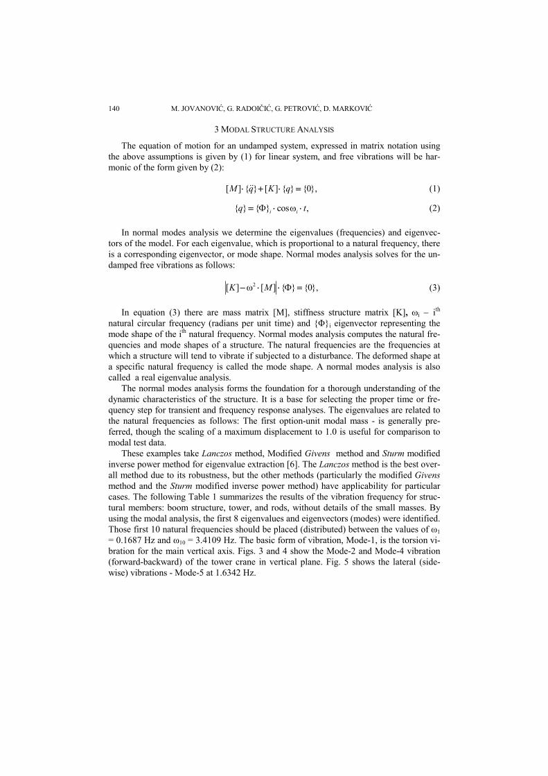
Let's look at the task of modeling on a supporting structure of a tower crane. The size of the structure and elasticity of the truss members will lead to big elastic displacements in extreme actions. This requires the nonlinear theory to be applied, based on the theory of finite deformations. The use of this theory is conditioned by the fact that moving of the striking points of external and internal forces is not negligible in relation to the structure dimensions. Modeling of such structures (Fig. 1), considering the mass of over ten tons, is performed by linear elements. For the structure analysis the FEM method is applied, while the computer realization is performed by numerical methods.
Fig. 2 shows that contemporary software tools [4, 5] can skillfully represent the geo-metrical complexity of the model. That refers primarily to the quality of the geometrical model form, visualization quality of the member structure form, orientation reliability and previous structure overshoots. These are the general quality elements of the contem-porary model development. Fig. 2 shows modeling based on real linear structure sections, the possibility of assigning kinematics freedom of member relations, color introduction as an element of recognizing parts within a structure. This enables the influence of other
Dynamical Models Quality of Truss Supporting Structures 139
present masses within the structure such as machineries, engines, reducers, coils, electri-cal equipment. Introducing precise concentrated masses into a model leads to a better quality - accuracy of solution. What's the quality of a contemporary truss supporting structure model, based only on linear members (beam, rod, and tie rod) is shown by this research. The biggest fault of line models (1D) is the complexity of mutual member rela-tions. Line members do not have any qualitative description of relations in the node.
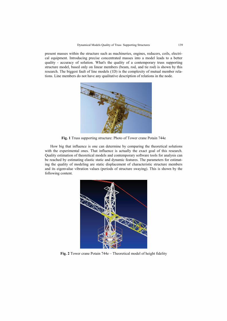
Fig. 1 Truss supporting structure: Photo of Tower crane Potain 744e
How big that influence is one can determine by comparing the theoretical solutions with the experimental ones. That influence is actually the exact goal of this research. Quality estimation of theoretical models and contemporary software tools for analysis can be reached by estimating elastic static and dynamic features. The parameters for estimat-ing the quality of modeling are static displacement of characteristic structure members and its eigenvalue vibration values (periods of structure swaying). This is shown by the following content.
Fig. 2 Tower crane Potain 744e – Theoretical model of height fidelity
140 M. JOVANOVIĆ, G. RADOIČIĆ, G. PETROVIĆ, D. MARKOVIĆ
3 MODAL STRUCTURE ANALYSIS
The equation of motion for an undamped system, expressed in matrix notation using the above assumptions is given by (1) for linear system, and free vibrations will be har-monic of the form given by (2):
[ ] { } [ ] { } {0},M q K q (1)
{ } { } cos ,i iq t (2)
In normal modes analysis we determine the eigenvalues (frequencies) and eigenvec-tors of the model. For each eigenvalue, which is proportional to a natural frequency, there is a corresponding eigenvector, or mode shape. Normal modes analysis solves for the un-damped free vibrations as follows:
2[ ] [ ] { } {0},K M (3)
In equation (3) there are mass matrix [M], stiffness structure matrix [K], i ith natural circular frequency (radians per unit time) and {Φ}i eigenvector representing the mode shape of the ith natural frequency. Normal modes analysis computes the natural fre-quencies and mode shapes of a structure. The natural frequencies are the frequencies at which a structure will tend to vibrate if subjected to a disturbance. The deformed shape at a specific natural frequency is called the mode shape. A normal modes analysis is also called a real eigenvalue analysis.
The normal modes analysis forms the foundation for a thorough understanding of the dynamic characteristics of the structure. It is a base for selecting the proper time or fre-quency step for transient and frequency response analyses. The eigenvalues are related to the natural frequencies as follows: The first option-unit modal mass - is generally pre-ferred, though the scaling of a maximum displacement to 1.0 is useful for comparison to modal test data.
These examples take Lanczos method, Modified Givens method and Sturm modified inverse power method for eigenvalue extraction [6]. The Lanczos method is the best over-all method due to its robustness, but the other methods (particularly the modified Givens method and the Sturm modified inverse power method) have applicability for particular cases. The following Table 1 summarizes the results of the vibration frequency for struc-tural members: boom structure, tower, and rods, without details of the small masses. By using the modal analysis, the first 8 eigenvalues and eigenvectors (modes) were identified. Those first 10 natural frequencies should be placed (distributed) between the values of ω1 = 0.1687 Hz and ω10 = 3.4109 Hz. The basic form of vibration, Mode-1, is the torsion vi-bration for the main vertical axis. Figs. 3 and 4 show the Mode-2 and Mode-4 vibration (forward-backward) of the tower crane in vertical plane. Fig. 5 shows the lateral (side-wise) vibrations - Mode-5 at 1.6342 Hz.

Dynamical Models Quality of Truss Supporting Structures 141
Fig. 3 Eigenvalue vibration Mode 2 forward-beck (ω2=0.47496 Hz)
Fig. 4 Eigenvalue vibration Mode 4 forward-beck (ω4=1.544465 Hz)
Fig. 5 Eigenvalue vibration Mode 5, Lateral vibration (ω5=1.63425 Hz)

142 M. JOVANOVIĆ, G. RADOIČIĆ, G. PETROVIĆ, D. MARKOVIĆ
Table 1. Example: review of theoretic values of basic frequencies structure P744e
Table I Mod-1 Mod-2 Mod-3 Mod-4 Mod-5 Mod-6 Mod-7 Mod-8 ωI [Hz] 0.1687 0.4749 0.5596 1.5444 1.6342 2.0274 2.5162 2.7747
A developed model is characterized by mass of MMOD=72.204, [kg], number of finite elements NELEMENT=1667, number of nodes NNODE=1146, and number of degrees of freedom NDOF=6876.
4 EXPERIMENTAL EXAMINATION OF FREE VIBRATIONS
The practical examination of model quality was done on a tower crane Potain 744e, with reach of 45m, elevating height 16m, total height 23.5m, and capacity of 10/2.35t at the reach of 14.8/45m. Fig. 6 shows the scheme of the measuring equipment for the dy-namical experimental analysis of the tower crane. The dynamical process of the free os-cillation is caused by the fast lowering of the load onto the ground. The sudden relieve of the load is followed by an expressive oscillation of the crane in the vertical plane, which corresponds to its second eigenvalue shape (Mode-2). Such a caused dynamic process has finally the character of free damped vibration. The vibration process is tracked down in the tower base by two strain gages, MG1 and MG2. The force on the hook is tracked down by a dynamometer, whereas the vertical crane-boom movement is tracked down di-rectly by a writer (reaching L). The measurement is made in MIN-KOPEX in 2011. The measuring amplifier HBM MGC+ and the strain gages HBM LY 10/120_ are used, and also a registration plotter of moving on paper and a dynamometer (force sensor) HBM U2A (10 t). Measurement is done by full measuring bridges with 6-channel (return) rela-tions of amplifier and sensor. The measured deformations of the tower base in the process of free oscillation (Fig. 7) are pure amortized oscillations of mechanical structure. These deformations (amplitudes) are regular without noises and without higher harmonics and are used for accurate determination of the structural damping coefficient. Processing one of the diagrams in Fig. 7 results in the diagram of the oscillation period of the structure in the tower base (in the damping regime), Fig. 8. The diagram shows the convergence of the oscillation period towards the stationary value of T=2.14 s and the empirical variance of oscillation Var(T)=0.0134098 (reaching L=20.88 m).
Fig. 9 shows a logarithmic decrement damping of free structure vibrations and its in-terpolation curve obtained on the base of a third-degree polynomial. Out of these numeri-cal procedures an average logarithmic decrement damping is determined: D‾ = 0.098605, with empirical variation of the statistical group: Var(D) = 0.007301768. The decrement is a medium measured value with n=50 diagram points, repeated on m=5 repeated meas-urements of structure deformation amplitudes, according to the schedule (4) and empirical variance according to the equation (5). Only parts of representative experimental curves of free damping vibration are observed according to Fig. 7. The crane structure is made of structural steel with modulus of elasticity E=2.1·1011 N/m2.
1
1 1
1 n m n
i jn
AD ln
m n A
(4)
2
1
1( ) ( )
1
n
i iiVar D D D
n
(5)

Dynamical Models Quality of Truss Supporting Structures 143
12HBM MGC Plus
MG2 MG1
PC Computer
m
z
MG1,MG2 - Measurement gage 1,2
HBM MGC Plus - Data acquisition system
1 - Translation in vertical direction
2 - Force Transducer
Legend:
23
.5 m
L=45 m
L=20.88 m
Translation
Force
Weight (load)
Deformation
20.5 m
Fig. 6 Layout of measuring devices on tower crane P744e. The diagram shows: Measurement system uses four sensors: Two strain gages (MG1, MG2) to measure the deformation of the structure, force sensor HBM U2A is also based on tensometric principle, and plotter of direct displacement of the boom on selected reach L
Fig. 7 Measurement No. 3: Free vibrations of steel structure - Tower crane P744e. The diagram: deformations of two opposite points MG1, MG2 (front-back) of tower base
This experimental fact, as well as its eigenvalue frequencies at which the vibration process proceeds, are necessary for finding a frequent or transient structure response to

144 M. JOVANOVIĆ, G. RADOIČIĆ, G. PETROVIĆ, D. MARKOVIĆ
external forced effects. The deformation diagrams are similar, shown by two curves, which are moved by 180°. The advantage of this way of measuring is in its getting clear non-filtered deformation signals.
Fig. 8 Decrease of damped vibration period – experimental results. Points for measuring the value of the curve interpolation process diagram of appeasement
Fig. 9 Logarithm decrement of damping – experimental results The average statistical value of the logarithmic decrement of structure damping is: D = 0.098605. The material of the structure is high quality structural steel
Dynamical Models Quality of Truss Supporting Structures 145
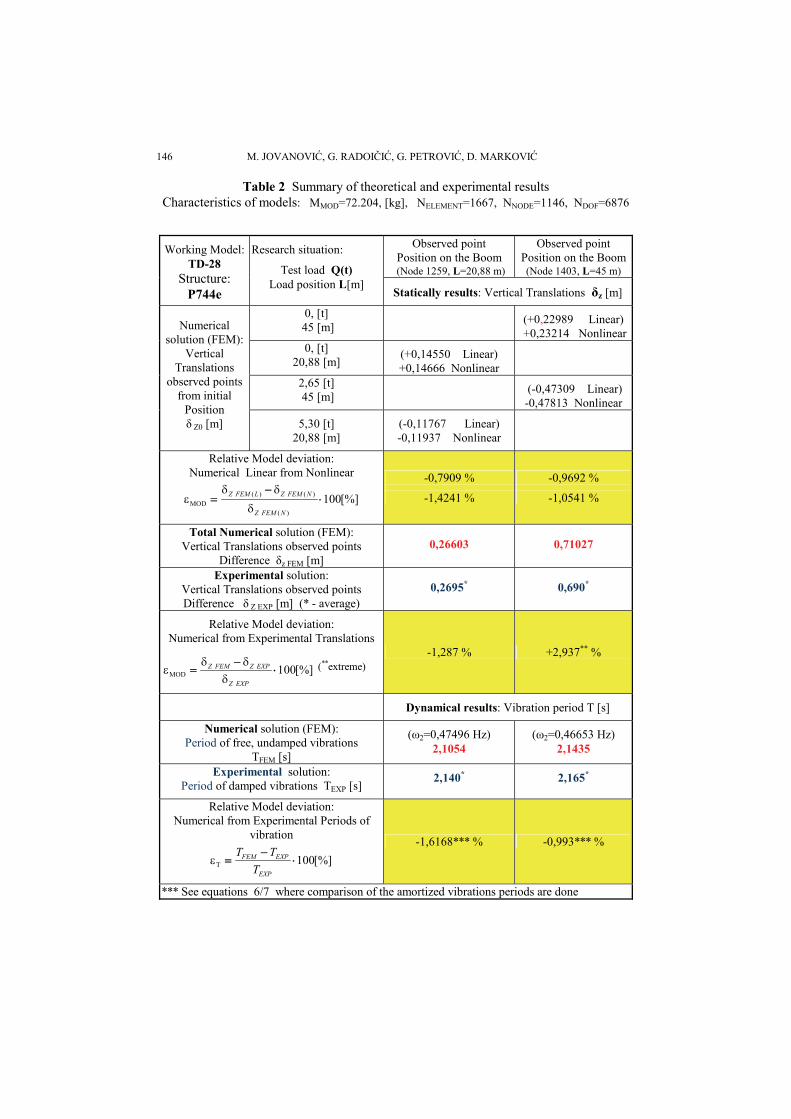
5 QUALITY ESTIMATION OF DYNAMICAL MODELS
Getting qualitative analytical solutions for large structures is a complex task and most often it cannot be realized at first step, taking into consideration that technical character-istics of the built-in structural parts must be known well. Despite the observed structural mass being 72 t, changes in boom translations (deflections) are important in each con-structive change of model members. Leading the model into a mathematically representa-tive status demands matching the measured static and dynamical parameters. When you have more measured parameters (strains, forces, movements, oscillation period and am-plitudes), there is only one solution - one mechanical model which really suits the behav-ior of the real physical structure. The more measured parameters, the more difficult it is to come to a qualitative dynamical structure model. However, it is a safe way for necessary model modifications which can describe the structure better. The following Table 2 gives a review of dynamical structure model verification results - by an experiment. The success is estimated by a relative error of the model displacement εMOD and relative error of swaying period εT. The relative error is calculated in relation to the experiment. The re-sults obtained by theoretical modeling of dynamical models refer to free damping vibra-tions and generally deviate from the measured damping vibrations. The correlation be-tween the period of damping oscillation (depreciated) TA and non-damping model T0, can be established by use of an oscillator with experimentally determined logarithmic decre-ment damping D, according to the bibliography [7] and relation (6). For the characteristic period of non-damping oscillation in vertical line (Mode-2, Fig. 3) T2=2.1054 s, nu-merically determined by crane reaching of L=20.88 m, without load, the corresponding approximate value of the damping vibration period is:
2 2
20.88 0
0.0986051 2.1054 1 2.10 [ ]AL
DT T Hz
(6)
A relative deviation of the main oscillation period of the theoretical model, deter-mined that way, from the experimentally determined period TEXP L=20.88 = 2.140 s, is = 1.4865 %.
In the same way the theoretical dynamical model is controlled reaching 45 m, and so the approximate value of the damping oscillation period, starting from the numerical value of the non-damping oscillation period T0 =2.1435 s (Mode-2), given by relation (7)
2 2
45 0
0.0986051 2.1435 1 2.14681 [ ]AL
DT T Hz
(7)
On the basis of equation (7), a relative deviation of the main oscillation period of the theoretical model, with the maximal reaching arrow, from the experimentally determined period TEXP L=45=2.165 s, is ε=-0.8473 %.
146 M. JOVANOVIĆ, G. RADOIČIĆ, G. PETROVIĆ, D. MARKOVIĆ
Table 2 Summary of theoretical and experimental results Characteristics of models: MMOD=72.204, [kg], NELEMENT=1667, NNODE=1146, NDOF=6876
Observed point Position on the Boom
(Node 1259, L=20,88 m)
Observed point Position on the Boom (Node 1403, L=45 m)
Working Model: TD-28
Structure: P744e
Research situation:
Test load Q(t) Load position L[m]
Statically results: Vertical Translations δz [m]
0, [t] 45 [m]
(+0,22989 Linear) +0,23214 Nonlinear
0, [t] 20,88 [m]
(+0,14550 Linear) +0,14666 Nonlinear
2,65 [t] 45 [m]
(-0,47309 Linear) -0,47813 Nonlinear
Numerical solution (FEM):
Vertical Translations
observed points from initial
Position δ Z0 [m]
5,30 [t] 20,88 [m]
(-0,11767 Linear) -0,11937 Nonlinear
Relative Model deviation: Numerical Linear from Nonlinear
( ) ( )MOD
( )
100[%]Z FEM L Z FEM N
Z FEM N
-0,7909 %
-1,4241 %
-0,9692 %
-1,0541 %
Total Numerical solution (FEM): Vertical Translations observed points
Difference δz FEM [m]
0,26603
0,71027
Experimental solution: Vertical Translations observed points Difference δ Z EXP [m] (* - average)
0,2695*
0,690*
Relative Model deviation: Numerical from Experimental Translations
MOD
100[%]Z FEM Z EXP
Z EXP
(**extreme)
-1,287 % +2,937** %
Dynamical results: Vibration period T [s]
Numerical solution (FEM): Period of free, undamped vibrations
TFEM [s]
(ω2=0,47496 Hz) 2,1054
(ω2=0,46653 Hz) 2,1435
Experimental solution: Period of damped vibrations TEXP [s]
2,140*
2,165*
Relative Model deviation: Numerical from Experimental Periods of
vibration
T 100[%]FEM EXP
EXP
T T
T
-1,6168*** % -0,993*** %
*** See equations 6/7 where comparison of the amortized vibrations periods are done
Dynamical Models Quality of Truss Supporting Structures 147
6 CRITERIA OF DYNAMICAL MODEL DEVELOPMENT
1. Accurate knowledge of construction and built-in masses in structures are necessary during the fabrication,
2. It is important to introduce all static features of the structure members, analyzing them to details,
3. It is important not to approximate but to respect criteria of real schedules and forms of truss members,
4. Introduction of secondary member masses, including machineries, motors, cables, stairs, platforms, joint constructions, electric equipment, reinforced concrete fundament,
5. It is necessary to represent the tie rod with one element of 1D class (rod) if oscilla-tion frequencies of the tower and the boom are required. In that way tie rod oscilla-tion modes are excluded,
6. The stiffness of the soil (C) must be modeled on the base of an experimentally deter-mined class of soil compressibility and experimental checking of fundament dis-placement to extreme dynamical effects,
7. Damping (logarithmic decrement) is also prone to change, 8. The finite element of beam with two nodes and 2x6 degrees of freedom is suitable
for the model, 9. Increasing the number of linear finite elements (1D) does not improve the model
convergence, 10. It is necessary to use advanced graphical processors for good member visualization, 11. A fast modeling is suitable for a competitive development of two parallel models
with two teams, 12. Model verification is successful only after one structure satisfies two static and dy-
namical trials at the same time (amplitudes, displacements), frequencies and the con-structive designer model,
13. Dynamical models function only after they give solutions which are followed by a constructive mass change,
14. A relative deviation of linear displacements from nonlinear analysis of elastic structures, such are tower cranes, in terms of geometrical influences has academic importance. The relative error is under 1.5 %, chart 2. This refers to elastic displacements limited to 1 m, and,
15. Dynamical models of new structures must be tracked down experimentally.
REFERENCES
1. Jovanović, M., Milić, P., 2002, Redundancy – The Design Criterion for Lattice Structured Tower Cranes, Proc. XVII International Conference on "Material flow, Machines and Devices in Industry", Mechanical Faculty University of Belgrade, Vol.1, pp.1.141-1.144. ISBN 86-7083-448-0.
2. Feng Fu., 2010, 3D Nonlinear Dynamic Progressive Collapse Analysis of Multi-storey Steel Composite Frame Buildings – Parametric Study, Engineering Structures, Vol.32, pp 3974-3980,
3. Radoičić G., Milić P., Jovanović M., 2011., Dynamic behavior of damaged Structure of Crane in the following incidental Event, The 7TH International Conference research and development of Mechanical elements and systems (IRMES '11), Mechanical Faculty University of Niš, Zlatibor 2011. Vol.1, pp.85-88. ISBN 978-86-6055-012-8.
4. THEORY REFERENCE, 2007, ANSYS, Inc.Southpointe 275, Technology Drive Canonsburg, PA 15317, SAS IP.Inc.
5. ADVANCED DYNAMIC ANALYSIS, MSC Nastran Version 70, User Documentation: 2004 MSC Software Corp. Nastran, Santa Ana, 2004.
148 M. JOVANOVIĆ, G. RADOIČIĆ, G. PETROVIĆ, D. MARKOVIĆ
6. Jovanović, M., Milić P., Janošević D., Petrović G, 2010, Accuracy of FEM analyses in Function of Finite Element Type selection, Facta Universitatis, Series Mechanical Engineering University Of Niš, Vol. 8, No1, 2010, Pp. 148 - 10.
7. Rašković, D, 1974, Theory of vibration, Civil Engineering Book, University of Belgrad, 1974, p. 68- 72. 8. Vacev, T., Kisin, S., Ranković, S., 2009, Experimental analysis of an original type of steel space truss
node joint, Facta Universitatis, Series Architecture and Civil Engineering Vol. 7, No 1, 2009, pp. 43 – 55.
KVALITET DINAMIČKIH MODELA REŠETKASTIH NOSEĆIH STRUKTURA
Miomir Jovanović, Goran Radoičić, Goran Petrović, Danijel Marković
Kvalitet modela kojim je opisana struktura je glavna vrednost naučnog izbora tehničkih analiza. Koliki je savremeni kvalitet dinamičkog modeliranja strukture primenom linijskih članova (1D konačnih elemenata) pokazan je ovom teorijsko-eksperimentalnom analizom. Posmatrana je struktura toranjske dizalice kao reprezenta velike strukture. Formiran je FEM model strukture koji je izložen testiranjima statičkih i dinamičkih svojstava. Tražene su elastične translacije i oblici oscilovanja modela. Numerički dobijena teorijska rešenja, poređena su eksperimentalnim rešenjima. Kvalitet primene savremenog modeliranja struktura dao je uglavnom odstupanja ispod 2 %. Na mestima izraženog savijanja rešetke, tamo gde je struktura tipa konzole, dobijena su odstupanja elastičnih pomeranja, ispod 3 %. Razlike rezultata teorijskih modela i eksperimentalnih ispitivanja upozoravaju na osetljivost kvaliteta modeliranja od iskustva autora i ograničenja teorijskih modela u opisu veza u čvoru rešetke. Rad ukazuje na elemente kvalitetnog modeliranja, obim primenjenog broja elemenata strukture, nepotrebnu detaljnost pojedinih opisa, važnost izbora tipa konačnih elemenata, eksperimentalne vrednosti prigušenja vibracija i svojstva toranjskih dizalica. Na osnovu ovih analiza moguće je razvijati analogne modele koji daju sigurnost kvalitetu – tačnost modeliranja odgovornih struktura.
Ključne reči: noseća struktura, toranjska dizalica, dinamičke osobine, modalna analiza, eksperimentalna provera, FEM modelovanje