Embed Size (px)
Citation preview
Available online at www.sciencedirect.com
Journal of Ocean Engineering and Science 2 (2017) 127–136 www.elsevier.com/locate/joes
Experimental evaluation of a hydrography surface vehicle in four
navigation modes
Hossein Mousazadeh
a , ∗, Jafarbiglu Hamid
a , Omrani Elham
a , Monhaseri Farshid
a , Kiapei Ali b , Salmani-Zakaria Yousef a , Makhsoos Ashkan
a
a Mechanical Engineering of Biosystems, University of Tehran, Iran b Mechanical Engineering of Biosystems, University of Shahrekord and Expert of Ports and Maritime Organization, Iran
Received 16 April 2017; accepted 15 May 2017 Available online 19 May 2017
Abstract
Considering the effectiveness of maritime transportation, a large number of world’s trade is carried by sea and ports. Monitoring ports and harbors are essential for 24 hourly loading/unloading of ships. In this regard, bathymetry and monitoring of depth data especially in real time manner would be very valuable and worthy. To plot hydrography map of ports and harbors in the bureau as online and with low
cost, a Surface Vehicle (SV) is designed and developed. This vehicle could navigate in four modes. Operator could seat on the boat and run by joystick or stand in slipway and control by Remote Controller (RC) or seat in the office and navigate by a user friend graphical interface. Finally the boat could navigate fully autonomous without any supervision. Comparison accuracy and precision of four mentioned navigation modes was the main objective of this research. Experimental results illustrated that autonomous mode with Standard Deviation (SD) of below 0.5 m was the most precision and comfortable mode, while RC is the more reliable and trustworthy. © 2017 Shanghai Jiaotong University. Published by Elsevier B.V. This is an open access article under the CC BY-NC-ND license. ( http://creativecommons.org/licenses/by-nc-nd/4.0/ )
Keywords: Autonomous, Navigation; Hydrography; Surface vehicle; Monitoring.
1
o
t
a
y
t
q
p
t
p
t
t
U
i
t
k
pr
w
r
e
v
v
h
(
c
U
c
t
h2(
. Introduction
Maritime transport is essential to the world’s economy asver 90% of the world’s trade is carried by sea and it is,he most cost-effective way to move goods and raw materialsround the world. This industry had increasing growth everyears. The world fleet grew by 3.5 percent in the 12 monthso 1 January 2016 (in terms of dead-weight tons). [1] . Conse-uently, a great part of the world’s economy depends on theorts and industries related to them. So successful moderniza-ion of this water transportation systems would be considered.
Some of the most cumbersome and important tasks inorts are 24 hourly monitoring and data collection. Sincehese operations susceptible for robotic and automatic con-rol, many researchers are focused on robot boats worldwide.nmanned marine vehicles (UMVs) are generally classified
∗ Corresponding author.
T
p
ttp://dx.doi.org/10.1016/j.joes.2017.05.003 468-0133/© 2017 Shanghai Jiaotong University. Published by Elsevier B.V. This http://creativecommons.org/licenses/by-nc-nd/4.0/ )
nto underwater and Surface Vehicles (SVs) with underwa-er vehicles currently taking the lion’s share of the mar-et because of their range of applications including subseaipeline/infrastructure surveying and inspection, search and
escue to name a few. Surface vehicles have also gained aidespread interest for applications ranging from oceanog-
aphy, remote sensing, weapons delivery, force multipliers,nvironmental monitoring, surveying and mapping, and pro-iding navigation and communication support to underwaterehicles [2] . In SVs category, an Autonomous Surface Ve-icle (ASV) is different from an Unmanned Surface VehicleUSV), which relies on a user to remotely operate the vehi-le. An ASV could operate without men supervision. Most ofSVs rely on remote operator guidance for sending mission
ommands and to constantly overlook the vehicle’s status ei-her by direct observation or via a wireless video link [3] .his adds to the operating cost of each mission and is notractical for extended periods of time [2] . Time, cost, safety
is an open access article under the CC BY-NC-ND license.
128 H. Mousazadeh et al. / Journal of Ocean Engineering and Science 2 (2017) 127–136
t
S
c
c
o
T
n
a
A
e
a
t
s
A
s
o
t
d
t
R
a
a
A
t
a
i
t
(
a
A
e
G
b
i
t
i
g
D
b
p
u
o
f
e
i
dd
i
s
t
a
w
t
b
and ease of use are some factors that are considered whencomparing the feasibility of ASVs to data collection and taskperformance methods [4] .
The use of autopilots for heading control during long tran-sits and long distance voyages had some first demonstratedin the 1920 s [5] . However, worldwide early ASV researchcan be traced back to the MIT Sea Grant college programin 1993. This prototype (ARTEMIS) was designed mainlyfor testing navigation and control systems for potential futureASVs. ARTEMIS was later used to collect simple bathymetrydata in Massachusetts. In 2003, the Navy implemented a unitin Iraq that can be deployed from a ship and controlled byNavy personnel to search for mines and allow for the safepassage of ships through dangerous waters. The Navy hasalso explored the use of USVs for harbor security and patrol.However, most vehicles used by the Navy today are not au-tonomous; they are simply remote controlled and accomplishtheir goal of removing the soldier from the scene [4] . Cur-rently there are a number of companies producing differenttypes of SVs not only for military establishments but also forindustrial corporations, environmental institutions and govern-ment agencies. SVs are finding their way into wider range ofcivilian applications as well. ASVs applications can be sortedin two fields:
(a) Environmental monitoring ; There is a great amount ofpotential in using ASVs to benefit our environment.ASVs can be applied to environmental monitoring tasks,which encompass many different types of data collec-tion and observation. There are other data collectionmethods such as satellite systems and networks of sta-tionary and floating buoys used today by scientists andresearchers; however there are limitations to these sys-tems, which include the range of buoy networks andthe accuracy and cost of satellite systems. In both ar-eas, ASVs can offer a solution or contribute as an addi-tional resource to collecting ocean data. Many more as-pects of environmental monitoring, such as mapping oilspills, have been explored to show how ASV technologycan help the environment. Some common applicationsfor environmental monitoring are; water salinity, wa-ter temperature, CO 2 content in air and sea, barometricpressure, wave height, wind speeds, bathymetry (waterdepth), photographic observation, underwater acoustics,oil spill measurements and pollution measurements [4] .
(b) Task performance ; some of the best applications fortask performance include; customizable sample collec-tion (e.g. Oil sample collection), defense related tasks,hazard clean up, beacon transmission, transportation,boat traffic markers and fish tracking [4] .
In military applications ASVs are used for different pur-poses, e.g. for patrol tasks, as scouts, or as a support formilitary ships [6] . Some candidate organizations that couldutilize ASVs are: WHOI, EPA, coast guard, harbor patrols,NOAA, National Marine Fisheries Service, National DataBuoy Center, oil companies, fisheries society, government sec-
ors, beachside resorts and businesses and Greenpeace, Seahepherd, and other environmental activist groups [4] . Ac-ording to researches, three autonomy levels in ASV wereontemplated; to have a human pilot on board, a remotelyperated unmanned ship, and an autonomous unmanned ship.he use of scaled ships for the last two levels is very conve-ient for experimental work [7] .
Since the current methods for surveying bathymetric datare slow and expensive, one of the feasible operation forSVs is hydrography or bathymetry. Rodriguez et al. (1996)
valuated an automated bathymetry mapping using ARTEMISnd a waypoint following controller based on fuzzy logichat was used to guide and control the vehicle. They demon-trated that real-time automated bathymetry mapping usingSV have the potential to perform high-quality bathymetry
urveys faster and more economically than conventional meth-ds [8] .
Beyond ASVs tasks, some researches are concentrated onhe navigation of this intelligent vehicles. Liu et al., (2014)eveloped an ASV, equipped with GPS and compass for au-onomous navigation in the paddy field. It is reported that theMS of lateral error was observed to be less than 0.45 m,nd the RMS heading error was 4.4 ° or less [9] . Elkins etl., (2010) developed an autonomy navigation system pack forSVs. Their research aimed to develop a mission level au-
onomous pack using Lidar, Radar, GPS, IMU, stereo sensorsnd fusion of data to keep it as modular. Although build-ng a boat was not objective of research, however they testedhe developed system by three platforms [10] . Escario et al.,2012) used ant algorithm to find optimal manoeuvres forn ASV. They used three degrees of freedom (3 DoF) forSV dynamic model and added mass’s assumed to be lin-
ar while damping ratio considered as quadratic order [11] .iron −Sierra et al., (2015) evaluated automatic spill recoveryy two unmanned boats. They used Dubins paths for exper-mental tests, which are composed of lines and circular arcshat is a classic method in mobile robotics [12] .
One recent research in environmental monitoring by ASVs performed by Tuna et al., (2013) that presented a navi-ation system for autonomous analyses of water quality (EC,O, pH, Temperature, Nitrate and Turbidity) using unmannedoats at drinking water reservoirs such as dams and holdingonds [13] . Chavez et al., (2017) used the Wave Glider (Liq-id Robotics, Inc.) for measurements of pCO2 and pH ofceans. This ASV is a self-propelled that uses wave-energyor propulsion and solar panels to power the vehicle-controllectronics and sensor payload. Field tests proven its capabil-ty of long-range ( > 5000 km) and long-duration ( > 500 day)eployments. The vehicle transits at speeds of 0.2 to 0.8 ms −1
epending on the sea state. It is concluded that the durabil-ty, autonomy, and low operational cost (relative to researchhips or oceanographic moorings) of these platforms createremendous potential for supplementing existing open-oceannd near-shore marine carbon dioxide observing efforts world-ide [14] . Savvaris et al., (2014) designed solar powered USV
o operate at sea for extended periods of time (up to 3-months)ut also have the capability to transit for a short range at high
H. Mousazadeh et al. / Journal of Ocean Engineering and Science 2 (2017) 127–136 129
Fig. 1. The Morvarid ASV is equipped with some sensors and systems.
s
b
[
t
e
m
s
f
f
d
e
i
A
H
b
m
t
2
f
h
n
m
c
o
s
T
t
s
n
l
fi
s
a
s
r
a
w
a
t
i
s
t
i
peeds [15] . Li et al., (2009) used an unmanned automatedoat for measurements of a small scale eddy at a tidal inlet16] . And Pereira et al., (2007) evaluated an ASV to studyhe effect of harmful algal blooms which is capable of op-ration in diverse marine environments such as lakes, rivers,arinas and harbors. The guidance system is equipped by a
tereo vision system for obstacles detection [17] . Considering the reviewed papers up to now, no comparison
or convenient and accuracy of navigation systems is reportedor SVs. So, in this research project, a prototype ASV iseveloped and it is aimed to demonstrate its capabilities forconomical hydrography. The long-term goal of this researchs to develop future generations of low cost, high-efficiencySV for oceanographic, industrial and environmental surveys.owever, the main objective of this research is to compareetween four different navigation modes of the ASV (manualode, remote control, from GUI and autonomous mode) and
o compare the results by simulation curves.
. Materials and methods
An ASV (titled as Morvarid
1 ) is designed and constructedor environmental survey and data monitoring tasks, especiallyydrography. Four components; a hull, propulsion system,
1 http:// emorvarid.ut.ac.ir/
m
G
d
avigation equipment and computer control, are the funda-ental building blocks of an autonomous system. Considering
ommon platforms, the twin-hulled catamaran design (madef fiberglass) is selected due to its stability and simplicity ofteering mechanism which is steered using differential thrust.he Morvarid is a plug-in hybrid solar powered ASV (by sun
racking system), with dimension about 3.8, 2.4 and 1.5 m ,re-pectively for length, width and height. An 8 kWh high tech-ology Li-ion battery pack, supply energy with endurance ateast three cloudy days without refueling. To perform the de-ned duty, according to Fig. 1 , the Morvarid is equipped withome local perception and global monitoring sensors such as; range finder Lidar, a set of ultrasonic sensors, three depth-canner sonar, a high resolution GNSS ( ∼0.5 m accuracy), oneeal time infrared camera, stereoscopic range finder system,n onboard industrial computer (IPC), a long-range ( ∼10 km)ireless connection system to another computer on land, an
uto-pilot system, an electric compass and two brushless con-inues variable electric motors (100 lbs). According to exper-mental tests the boat can achieve 5 knot maximum cruisingpeeds and its overall weight is about 700 kg.
This SV is consisted of some subsystems mainly naviga-ion system. It can navigate in four modes, the virtue thats not found in another similar ASVs. These four navigationodes have priority order as; manual, remote control (RC),UI and autonomous. Some subsystems of Morvarid SV isemonstrated as below.
130 H. Mousazadeh et al. / Journal of Ocean Engineering and Science 2 (2017) 127–136
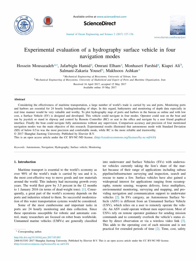
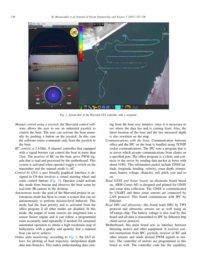
Fig. 2. Screen-shot of the Morvarid GUI controller with a waypoint.
Manual control using a joystick ; the Morvarid control soft-ware allows the user to use an industrial joystick tocontrol the boat. The user can activate the boat manu-ally by pushing a button on the joystick. In this casethe software routes commands only from the joystick tothe boat.
RC control ; a 2.4 GHz, 8 channel controller that equippedwith a signal booster can control the boat in more than2 km. The receiver of RC on the boat, gives PWM sig-nals that is read and processed by the motherboard. Thissystem is activated when operator toggle a switch on thetransmitter and the manual mode is off.
Control by GUI ; a user friendly graphical interface is de-signed in C# that involves a virtual steering wheel andsome control buttons ( Fig. 2 ). Operator could activatethis mode from bureau and observes the boat scene byreal-time IR-camera in the desktop.
Autonomous mode ; the goal of the Morvarid project in au-tonomous mode has been to create a system that can actautonomously to perform mission-level behavior. Thismode had the least priority and is activated from theoffice program if all other modes are disabled. In thismode, the output of some sensors are integrated into asensor fusion engine and it can follow a programmedroute accurately (and repeatedly if needed) for sustainedautomated operation to obtain a high resolution map ofbathymetry with a quality and quantity that a mannedboat can never achieve.
Online data monitoring; according to Fig. 2 , the GUI al-lows for plotting of boat trajectory, interpolated depthdata and obstacles. This makes understanding data com-
ing from the boat very intuitive, since it is necessary tosee where the data has and is coming from. Also, thelatest location of the boat and the last measured depthis also rewritten on the map.
Communications with the boat; Communication betweenoffice and the IPC on the boat is handled using TCP/IPsocket communications. The IPC runs a program that isas server which accepts communications from clients ona specified port. The office program is a client, and con-nects to the server by sending data packet as bytes withabout 10 Hz. This information packet include GNSS lat-itude, longitude, heading, velocity, sonar depth, temper-ature, battery voltage, obstacles, roll, pitch, yaw and soon.
Read GNSS and Sonar board ; an electronic board basedon, ARM Cortex M3 is designed and printed for GNSSand sonar data collection. The GNSS is communicatedby USART and three sonar sensors are connected byLAN protocol. This board communicate with IPC byEthernet.
Read IMU and ultrasonic ; this board reads IMU by TWIprotocol and ultrasonic sensors set as well using anATxmega chip. The battery voltage is also read by thisboard and all data is transmitted to IPC by Ethernet httpclient-server protocol;
Motherboard; this main board acts as interface betweenthrusting motors and other equipment. It receives con-trol instructions from IPC, joystick, receiver of RC andother sensors and sends desired PWM signals to mo-tors. The controller of motors are programmed in thisboard as well. The controller code has the capability

H. Mousazadeh et al. / Journal of Ocean Engineering and Science 2 (2017) 127–136 131
2
m
t
(
c
t
t
s
y⎧⎪⎪⎪⎪⎪⎪⎪⎪⎪⎪⎪⎪⎨⎪⎪⎪⎪⎪⎪⎪⎪⎪⎪⎪⎪⎩
n
a
t
a
r
b
a
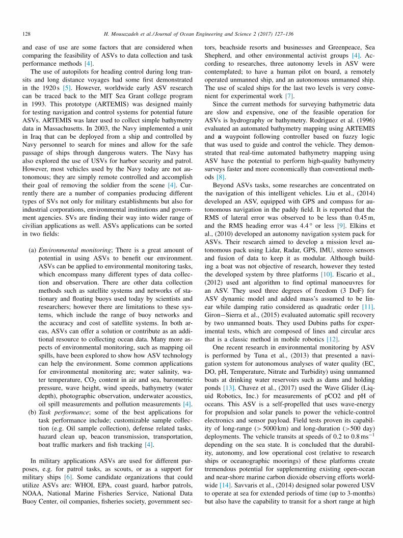
Fig. 3. Calibration of depth - sonar sensors.
i
m
i
w
f
i
[
g
fi
fi
g
t
i
t
i
u
a
2
fi
T
ds
m
S
t
a
m
i
i
a
w
p
a
T
to take on either proportional only or PID controllerforms.
The office software of Morvarid; The Morvarid office soft-ware has five parts; (a) obstacle monitor, (b) IR cam-era data, (c) the control and guidance section, (d) theboat statues bar and (e) plotting section that hydrogra-phy data sketched on it ( Fig. 2 ). This application wasdeveloped in Visual C#, and has some other forms thatwould be selected from main menu. The user can selectfrom a set of tab-pages to decide what he/she wants todo with the boat. If user wants to create only a path forthe boat, they can click on it on the calibrated map andgenerate a mission file (with the corresponding latitudelongitude pairs) for the boat to begin execution. Andalso the user can unable the path and activate for anyof the three sonar data plotting or all sonar data plottingsimultaneously. The software allows a user to import arectified aerial picture of the region of operation eitherfrom any source that provides linearly scaled maps suchas Google Earth. After the picture has been loaded, thesoftware allows the user to calibrate the map using atwo point calibration. Once a calibrated map has beenloaded, the user can connect to the boat and view theboat on the display overlaid on the map in the form ofa red arrow.
.1. Control, guidance and navigation equations
The mathematical model of underactuated Morvarid boatoving in surge, sway and yaw is obtained from the mo-
ion equation of the ship moving in six degrees of freedomDOF) under disturbances induced by wave, wind and oceanurrent according to Fossen (1996) [18] . For surface vehicleshe depth z and pitch θ variables are not applicable. Alsohe roll ϕ variation is found to be negligible. So with someimplifications the Morvarid boat moving in surge, sway andaw can be described as Eq. (1) [19] ;
˙ x = u.cosψ − υ.sinψ
˙ y = u.sinψ + υ.cosψ
˙ ψ = r
˙ u =
m 22 m 11
.v.r − d u m 11
.u −3 ∑
i=2
d ui m 11
| u
| i−1 .u +
1 m 11
. τu +
1 m 11
. τwu ( t )
˙ υ =
m 11 m 22
.u.r − d υm 22
.υ −3 ∑
i=2
d υi m 22
| υ| i−1 .υ +
1 m 22
. τwυ ( t )
˙ r =
( m 11 −m 22 )
m 33 .u.υ − d r
m 33 .r −
3 ∑
i=2
d ri m 33
| r | i−1 .r +
1 m 33
. τr +
1 m 33
. τwr
(1)
All parameters of Eq. (1) are defined in [19] . After defi-ition of ASV model, the Extended Kalman Filter (EKF) ispplied for path prediction. In estimation theory, the EKF ishe nonlinear version of the Kalman Filter which linearizesbout an estimate of the current mean and covariance. Theequired data in measurement equation of EKF is providedy GNSS and IMU. For path following and obstacle avoid-nce, Artificial Potential Field (APFs) algorithms is used that
s one of the most common algorithm operates according toagnetic potential field (i.e. attractive or repulsive force are
nversely proportional to distance from destination point). Theell-known limitation of APF is mainly pertaining to a need
or more robust exceptions handling, addressing the local min-ma issues and a need for more complex encounter scenariosA Reactive COLREGs]. Considering this limitations an al-orithm is developed based on the combination of potentialeld and research ball algorithms [19] . The ball radius is de-ned by the user, that for this experiment it is adjusted to fouroal points. The goal points are series of destination pointshat are meshed in the start of the program by a distance thats defined by user, in about 3–8 m. Before experimental testshe developed algorithm based on EKF, APF and research balls simulated using a developed program in Visual C# to eval-ate the robustness and confidantes of the developed NGClgorithm.
.2. Experimental evaluation
Overall experimental tests are conducted three times. Therst and second tests are performed in Persian Gulf Lake, inehran. In these two tests some parameters as energy en-urance, platform stability, forward/backward velocity, and
ensors accuracy and so on are evaluated. The third experi-ent that is matter of this research is accomplished in Caspianea in 40 days ( Fig. 3 ). It is mainly aimed to evaluate be-
ween four navigation modes and considering which mode isccurate, reliable and comfortable. Fig. 3 shows the experi-ental calibration process of depth sonars. To compare accuracy and precision of the mobile robot
n four developed modes, a “snake-shaped” navigation maps designed to ASV platform ran around (as Giron −Sierra etl., (2015) that used Dubins paths [12] ). The navigation mapas generated into three paths. The path space and “goaloints” distance was adjustable in the beginning of each testnd position of the start point in first paths were according toable 1 . In each navigation map, the ASV platform ran line

132 H. Mousazadeh et al. / Journal of Ocean Engineering and Science 2 (2017) 127–136
Table 1 Experimental test conditions.
Navigation mode Start point ( X 1 , Y 1 ) Line length [m]
Lines space [m]
Lines orientation Average speed [km/hr]
Wind speed - direction [m/s]
Manual (36.856201,53.366712) 200 100 N-S & S-N 3 6 (N-E) RC (36.856201,53.366712) 200 100 N-S & S-N 2.8 6 (N-E) GUI (36.856451,53.369000) 150 25 W-E & E-W 1.4 6.5 (S-E) Auto. (36.856451,53.369000) 150 25 W-E & E-W 1.1 6.5 (S-E)
S
R
y
i
3
n
s
w
t
s
P
a
i
c
c
n
i
g
d
i
m
p
l
A
c
i
a
i
c
c
C
f
following navigation from start point, then, run turning con-trol to the subsequent path. It was circularly executed untilfinishing all the three desired paths. This process was con-ducted three times at defined speed and it is steered linearlyfrom the start point ( X 1 , Y 1 ) to the next destination point( X 2 , Y 2 ).
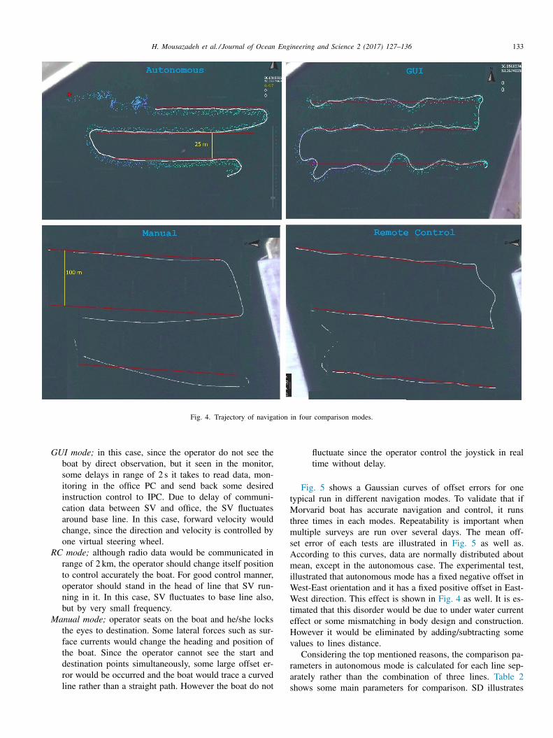
In autonomous mode, user clicks to four points as edgeof a rectangular in the map and enters some values to “linesdistance” and distance between points on the lines. These val-ues as well as latitude and longitude of selected points aretransmitted to onboard IPC on the boat. The IPC program,meshes the path in West-East orientation and the boat startsthe mission. After navigation starting, using high range Wi-Fi communication, the requested data such as depth, velocity,temperature and etc. is received in office. Depth data fromdifferent sonars are plotted as a cloud points on the map us-ing a color panel. In the autonomous navigation control, afterline-following navigation, the ASV should turn around at theend waypoint position to enter the subsequent path. The navi-gation map is normally designed as parallel paths. Obviously,the heading of the ASV platform should rotate 180 ° whendoing turning. According to test results, the Morvarid ASVcan turn in approximately zero turning radius. Although thepath is designed as Dubins path, the line-following naviga-tion is the main part of the navigation modes. The goal ofthe autonomous algorithm was to minimize both the lateralerror and heading error to follow the target line. Fig. 4 showsthe trajectory of line-following navigation in four comparisonmodes. The red lines are desired paths and the white path isthe line-following travelled trajectory of the ASV platform inreal time. One of three repetition in four modes are illustratedin Fig. 4 for typically.
To compare four navigation modes, some parameters areevaluated. The RMSE, Standard Deviation (SD), Range, av-erage, Max and Min of offset was some parameters that arederived for evaluation according to Eqs. (2) −(4) . The offsetof the vehicle is its lateral displacement with respect to ahypothetical line that is parallel to the center plane of the ve-hicle and crosses the target point. The error signal is recordedevery 40 cm approximately. It is considered that each desiredline is as base line, and error points on top of the desiredpath is taken positive, while below path it is regarded as mi-nus. The Gaussian curve of each test is sketched as well forassessment.
RMSE =
√ ∑ n i=1
(y i − ˆ y i
)2
n
(2)
D =
√ ∑ n i=1 ( y i − y ) 2
n
(3)
= max − min (4)
In these equations y i is the boat offset error in i th point,ˆ i is predicted value of offset error (zero in this case) and ys average of n offset errors.
. Results and discussion
To evaluate performance of the Morvarid SV in fouravigation modes, the results of experimental tests are pre-ented here. These tests displayed the vehicle behaviors foraypoint-following. Numerous experiments were performed
o validate the components and subsystems of the Morvaridystem. All practical tests were conducted at the Amir −Abadort in the Caspian Sea. Although Morvarid can perform fullyutonomously, the next three navigation methods also can runf necessary. In GUI mode some basic supervisory controlommands such as start, stop, direction, velocity, emergencyut off, mother board reset and so on can be sent via wirelessetwork. Similar commands would be sent via radio networkn RC mode. During a bathymetry survey, Morvarid navi-ates along predefined/arbitrary tracks while recording someata such as readings from the depth sounder. The track spac-ng is chosen to provide the desired spatial resolution of theap. While the boat is surveying, bathymetric and geodetic
osition data are sent to the office computer through a wire-ess network and a bathymetry map is created in real-time.ll data are also stored in onboard IPC in Morvarid. Upon
ompletion of a mission in autonomous mode, the boat stopn the last goal point and it is recovered by GUI or RC modesnd data are retrieved. Although the Morvarid SV can turnn approximately zero turning radius at the end of paths, butomparison for turning path is not aim of this research. Soomparison is performed only considering the right line path.onsidering Fig. 4 that is given typically, some overall results
rom experiments are concluded;
Autonomous mode; the ASV runs in top of the path linein W-E direction and below the path line in E-W direc-tion without crossing the line. The boat navigate withapproximately constant speed that is defined by the al-gorithm, so it runs very smoothly and calm without anyknock to the boat body.
H. Mousazadeh et al. / Journal of Ocean Engineering and Science 2 (2017) 127–136 133
Fig. 4. Trajectory of navigation in four comparison modes.
t
M
t
m
s
A
m
i
W
W
t
e
H
v
r
a
s
GUI mode; in this case, since the operator do not see theboat by direct observation, but it seen in the monitor,some delays in range of 2 s it takes to read data, mon-itoring in the office PC and send back some desiredinstruction control to IPC. Due to delay of communi-cation data between SV and office, the SV fluctuatesaround base line. In this case, forward velocity wouldchange, since the direction and velocity is controlled byone virtual steering wheel.
RC mode; although radio data would be communicated inrange of 2 km, the operator should change itself positionto control accurately the boat. For good control manner,operator should stand in the head of line that SV run-ning in it. In this case, SV fluctuates to base line also,but by very small frequency.
Manual mode; operator seats on the boat and he/she locksthe eyes to destination. Some lateral forces such as sur-face currents would change the heading and position ofthe boat. Since the operator cannot see the start anddestination points simultaneously, some large offset er-ror would be occurred and the boat would trace a curvedline rather than a straight path. However the boat do not
fluctuate since the operator control the joystick in realtime without delay.
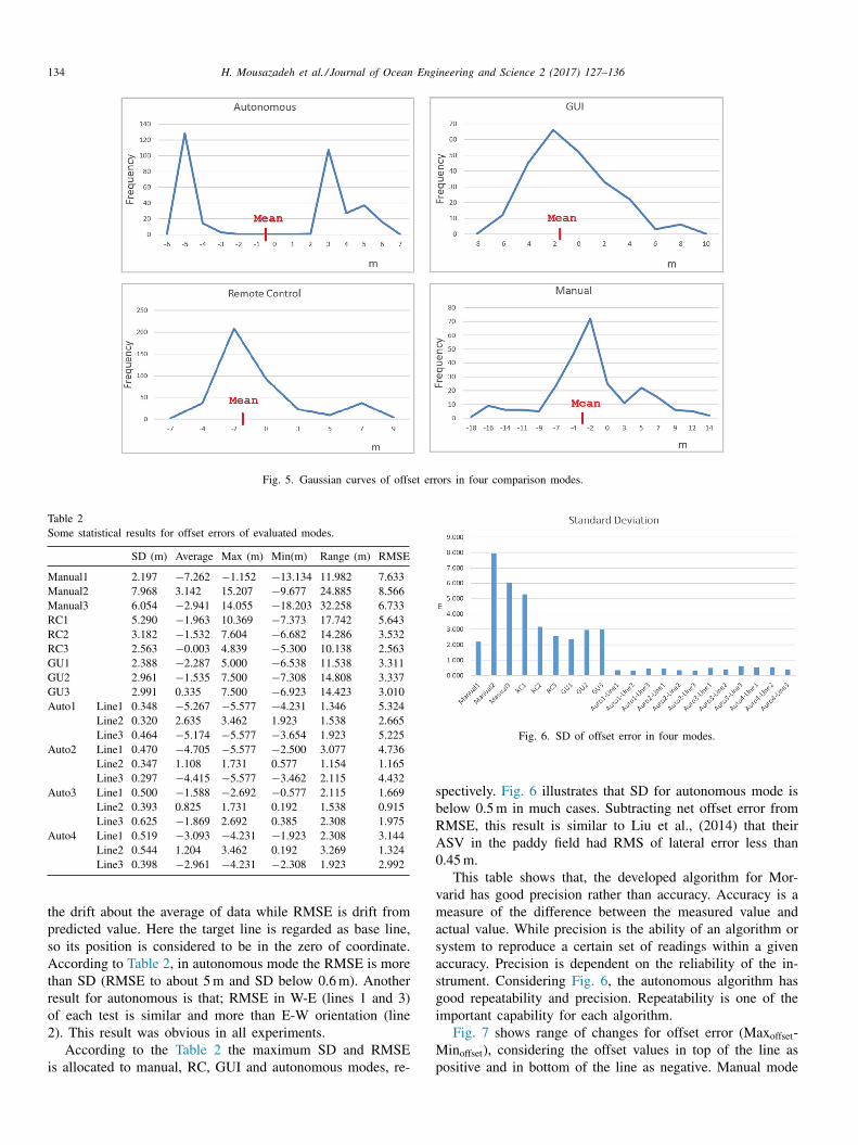
Fig. 5 shows a Gaussian curves of offset errors for oneypical run in different navigation modes. To validate that if
orvarid boat has accurate navigation and control, it runshree times in each modes. Repeatability is important when
ultiple surveys are run over several days. The mean off-et error of each tests are illustrated in Fig. 5 as well as.ccording to this curves, data are normally distributed aboutean, except in the autonomous case. The experimental test,
llustrated that autonomous mode has a fixed negative offset inest-East orientation and it has a fixed positive offset in East-est direction. This effect is shown in Fig. 4 as well. It is es-
imated that this disorder would be due to under water currentffect or some mismatching in body design and construction.owever it would be eliminated by adding/subtracting somealues to lines distance.
Considering the top mentioned reasons, the comparison pa-ameters in autonomous mode is calculated for each line sep-rately rather than the combination of three lines. Table 2hows some main parameters for comparison. SD illustrates
134 H. Mousazadeh et al. / Journal of Ocean Engineering and Science 2 (2017) 127–136
Fig. 5. Gaussian curves of offset errors in four comparison modes.
Table 2 Some statistical results for offset errors of evaluated modes.
SD (m) Average Max (m) Min(m) Range (m) RMSE
Manual1 2.197 −7.262 −1.152 −13.134 11.982 7.633 Manual2 7.968 3.142 15.207 −9.677 24.885 8.566 Manual3 6.054 −2.941 14.055 −18.203 32.258 6.733 RC1 5.290 −1.963 10.369 −7.373 17.742 5.643 RC2 3.182 −1.532 7.604 −6.682 14.286 3.532 RC3 2.563 −0.003 4.839 −5.300 10.138 2.563 GU1 2.388 −2.287 5.000 −6.538 11.538 3.311 GU2 2.961 −1.535 7.500 −7.308 14.808 3.337 GU3 2.991 0.335 7.500 −6.923 14.423 3.010 Auto1 Line1 0.348 −5.267 −5.577 −4.231 1.346 5.324
Line2 0.320 2.635 3.462 1.923 1.538 2.665 Line3 0.464 −5.174 −5.577 −3.654 1.923 5.225
Auto2 Line1 0.470 −4.705 −5.577 −2.500 3.077 4.736 Line2 0.347 1.108 1.731 0.577 1.154 1.165 Line3 0.297 −4.415 −5.577 −3.462 2.115 4.432
Auto3 Line1 0.500 −1.588 −2.692 −0.577 2.115 1.669 Line2 0.393 0.825 1.731 0.192 1.538 0.915 Line3 0.625 −1.869 2.692 0.385 2.308 1.975
Auto4 Line1 0.519 −3.093 −4.231 −1.923 2.308 3.144 Line2 0.544 1.204 3.462 0.192 3.269 1.324 Line3 0.398 −2.961 −4.231 −2.308 1.923 2.992
Fig. 6. SD of offset error in four modes.
s
b
R
A
0
v
m
a
s
a
s
g
i
M
p
the drift about the average of data while RMSE is drift frompredicted value. Here the target line is regarded as base line,so its position is considered to be in the zero of coordinate.According to Table 2 , in autonomous mode the RMSE is morethan SD (RMSE to about 5 m and SD below 0.6 m). Anotherresult for autonomous is that; RMSE in W-E (lines 1 and 3)of each test is similar and more than E-W orientation (line2). This result was obvious in all experiments.
According to the Table 2 the maximum SD and RMSEis allocated to manual, RC, GUI and autonomous modes, re-
pectively. Fig. 6 illustrates that SD for autonomous mode iselow 0.5 m in much cases. Subtracting net offset error fromMSE, this result is similar to Liu et al., (2014) that theirSV in the paddy field had RMS of lateral error less than.45 m.
This table shows that, the developed algorithm for Mor-arid has good precision rather than accuracy. Accuracy is aeasure of the difference between the measured value and
ctual value. While precision is the ability of an algorithm orystem to reproduce a certain set of readings within a givenccuracy. Precision is dependent on the reliability of the in-trument. Considering Fig. 6 , the autonomous algorithm hasood repeatability and precision. Repeatability is one of themportant capability for each algorithm.
Fig. 7 shows range of changes for offset error (Max offset -in offset ), considering the offset values in top of the line as
ositive and in bottom of the line as negative. Manual mode
H. Mousazadeh et al. / Journal of Ocean Engineering and Science 2 (2017) 127–136 135
Fig. 7. Range of offset error in four modes.
s
o
t
A
w
i
n
a
y
p
e
fi
c
d
p
F
fi
d
t
m
M
f
a
t
A
i
t
i
a
r
d
R
b
4
f
t
a
f
a
t
P
m
i
a
l
t
s
t
t
fl
hows the maximum value of range, since in this case theperator targeted to a destination point in front of the boat inhe offshore rather following a virtual/actual line in the water.lthough floating a rope tightened to some balls in surface ofater is possible and it is done in this experiment, however
t is not applicable for practical hydrography. So the result isot compared here.
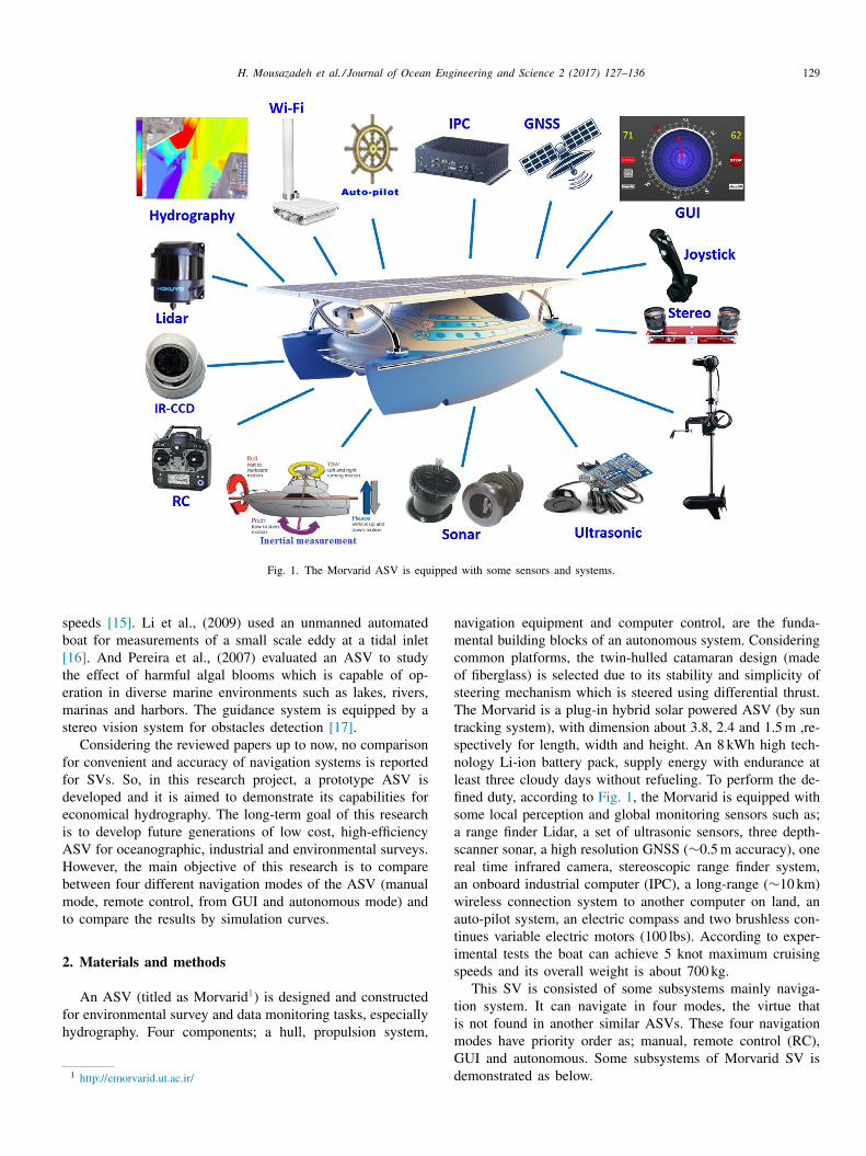
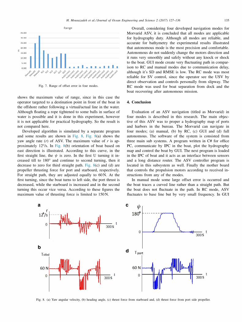
Developed algorithm is simulated by a separate programnd some results are shown in Fig. 8 . Fig. 8 (a) shows theaw angle rate ( r ) of ASV. The maximum value of r is ap-roximately 12
o /s. In Fig. 8 (b) orientation of boat based onast direction is illustrated. According to this curve, in therst straight line, the ψ is zero. In the first U turning it in-reased till to 180 ° and continue to second turning, then itecrease to zero for third straight path. Fig. 8 (c) and (d) areropeller thrusting force for port and starboard, respectively.or straight path, they are adjusted equally to 60 N. At therst turning, since the boat turns to left side, the port thrust isecreased, while the starboard is increased and in the secondurning this occur vice versa. According to these figures theaximum value of thrusting force is limited to 150 N.
Fig. 8. (a) Yaw angular velocity, (b) heading angle, (c) thrust force
Overall, considering four developed navigation modes fororvarid ASV, it is concluded that all modes are applicable
or hydrography duty. Although all modes are reliable, andccurate for bathymetry the experimental results illustratedhat autonomous mode is the most precision and comfortable.utonomous do not suddenly change the motors direction and
t runs very smoothly and safely without any knock or shocko the boat. GUI mode create very fluctuating path in compar-son to RC and manual modes due to communication delay,lthough it’s SD and RMSE is low. The RC mode was mosteliable for SV control, since the operator see the USV byirect observation and controls personally from slipway. TheC mode was used for boat separation from dock and theoat recovering after autonomous mission.
. Conclusion
Evaluation of an ASV navigation (titled as Morvarid) inour modes is described in this research. The main objec-ive of this ASV was to proper a hydrography map of portsnd harbors in the bureau. The Morvarid can navigate inour modes; (a) manual, (b) by RC, (c) GUI and (d) fullutonomous. The software of the system is consisted fromhree main sub systems. A program written in C# for officeC, communicate by IPC in the boat, plot the hydrographyap and control the boat by GUI. The next program is loaded
n the IPC of boat and it acts as an interface between sensorsnd a long distance router. The ASV controller program isocated in this subsystem as well. Finally the mother boardhat controls the propulsion motors according to received in-tructions from any of the modes.
In manual mode some large offset error is occurred andhe boat traces a curved line rather than a straight path. Buthe boat does not fluctuate in the path. In RC mode, ASVuctuates to base line but by very small frequency. In GUI
from starboard and, (d) thrust force from port side propeller.
136 H. Mousazadeh et al. / Journal of Ocean Engineering and Science 2 (2017) 127–136
[
[
[
[
[
[
[[
[
[
mode, due to delay of data communication between ASV andoffice, the ASV fluctuates around base line. In autonomousmode, the ASV runs very smoothly and calm without anyknock to the boat body. It has a constant offset error to baseline that would be removed by adding/subtracting some valuesto lines distance. Finally it is concluded that all modes areenough reliable, and accurate for bathymetry duty. Accordingto experiments the autonomous mode is the most precisionand comfortable mode. This navigation mode had lowest SDand RMSE. The most reliable mode was RC that is usedfor boat separation from dock and the boat recovering afterautonomous mission.
Acknowledgment
Authors would like to acknowledge the Ports and MaritimeOrganization for funding the Morvarid Project no. 20S/7509 .2015-2017.
References
[1] Anonym. Accessed in May 2017. Available in; https://business.un.org/ en/ entities/ 13 .
[2] W. Naeem , S.C. Henrique , L. Hu , A reactive COLREGs-Compliant nav-igation strategy for autonomous maritime navigation. IFAC conferencearchive (2016) 207–213 .
[3] S.J. Corfield , J.M. Young , IET Control Eng. Ser. (69). Chapter 15 (2008)311–326 .
[4] D. Rodriguez, M. Franklin, C. Byrne. https:// web.wpi.edu/ Pubs/ E-project/ Available/ E-project-121212.../ASV _ IQP.pdf) , 2012 .
[5] D. Manda , M.W. Thein , A. D’Amore , A. Armstrong , in: Proceedingsof the U.S. Hydrographic Conference, MD, National Harbor, 2015,pp. 16–19 .
[6] T. Praczyk , Neurocomputing 149 (2015) 559–572 . [7] J.M. Giron-Sierra , A.T. Gheorghita , G. Angulo , J.F. Jimenez , Ocean
Eng. 95 (2015) 23–33 . [8] C.D. Rodriguez-Ortiz , M.Sc. thesis in ocean engineering, Massachusetts
Institute of Technology (MIT), 1996 . [9] Y. Liu , N. Noguchi , T. Yusa , in: Proceedings of the 19th World
Congress International Federation of Automatic Control, Cape Town,South Africa, 2014 .
10] L. Elkins , D. Sellers , W.R. Monach , J. Field Robot. 27 (6) (2010)790–818 .
11] J.B. Escario , J.F. Jimenez , J.M. Giron-Sierra , Expert Syst. Appl. 39(2012) 10120–10139 .
12] A.T. Giron-Sierra J.M. Gheorghita , G. Angulo , J.F. Jimenez , Ocean Eng.95 (2015) 23–33 .
13] G. Tuna , O. Arkoc , G. Koulouras , S.M. Potirakis , Elektron. IR Elek-trotech. 19 (8) (2013) 3–7 .
14] F.P. Chavez, J. Sevadjian, C. Wahl, J. Friederich, G.E. Friederich, Mea-surements of pCO2 and pH from an autonomous surface vehicle in acoastal upwelling system. Deep-Sea Research Part II., 2017 Acceptedpaper, Available online 9 January 2017 https:// doi.org/ 10.1016/ j.dsr2.2017.01.001 .
15] H. Savvaris A. Niu , H. Oh , A. Tsourdos , in: Proceedings of the 19thWorld Congress of the International Federation of Automatic Control,Cape Town, South Africa, 2014 .
16] C. Li , E. Weeks , J. Mar. Syst. 75 (2009) 150–162 . 17] A.A. Pereira , Navigation and Guidance of an Autonomous Surface Ve-
hicle., University of Southern California, 2007 M.Sc. Thesis . 18] T.I. Fossen , Guidance and Control of Ocean Vehicles, John Wiley and
Sons, 1994 . 19] H. Mousazadeh , H. Jafarbiglu , H. Abdolmaleki , E. Omrani , F. Mon-
haseri , M. Abdollahzadeh , A. Mohammadi-Aghdam , A. Kiapei ,Y. Salmani-Zakaria , A. Makhsoos A. , H. Azimi , M.A. Mousapour–Gorji , A Navigation Algorithm For An Unmanned Boat. Proceeding inInternational conference, ICOPMAS (2016) 253–255 .