Embed Size (px)
Citation preview
7th ECCOMAS Thematic Conference on Smart Structures and Materials
SMART 2015
A.L. Araúo, C.A. Mota Soares, et al. (Editors)
c© IDMEC 2015
EXPERIMENTAL INVESTIGATION OF A COMPLIANTMECHANISM FOR AN UAV LEADING EDGE
Martin Radestock∗, Johannes Riemenschneider†, Hans-Peter Monner§, Michael Rose‡
German Aerospace Center (DLR)Institute of Composite Structures and Adaptive Systems
Lilienthalplatz 7, 38108 Braunschweig, Germany∗E-mail: [email protected], † E-mail: [email protected]
§ E-mail: [email protected], ‡ E-mail: [email protected]
Keywords: Morphing leading edge, topology optimisation, morphing unmanned aerial vehi-cle, compliant mechanism.
Summary. A description of a framework for a morphing leading edge will be given. Theconsidered aircraft is an unmanned aerial vehicle with a span of 4 m. The first step of theframework is a skin optimisation with the main objective to realise a skin layup and a loadintroduction point in order to match given aerodynamic shapes. The second step is a topologyoptimisation to realise a kinematic inside the leading edge with a compliant mechanism. Dueto ideal boundary conditions the simulation results have to be post processed for manufactur-ing. The experimental investigation will clarify the divergence between the simulation and themanufactured kinematic. The main objective of the experiments will be the deformation and thestrain in the mechanism.
1. INTRODUCTION
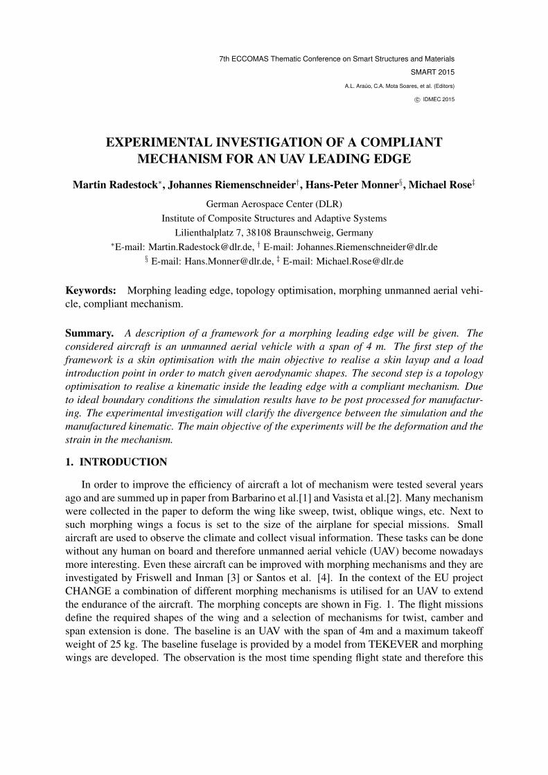
In order to improve the efficiency of aircraft a lot of mechanism were tested several yearsago and are summed up in paper from Barbarino et al.[1] and Vasista et al.[2]. Many mechanismwere collected in the paper to deform the wing like sweep, twist, oblique wings, etc. Next tosuch morphing wings a focus is set to the size of the airplane for special missions. Smallaircraft are used to observe the climate and collect visual information. These tasks can be donewithout any human on board and therefore unmanned aerial vehicle (UAV) become nowadaysmore interesting. Even these aircraft can be improved with morphing mechanisms and they areinvestigated by Friswell and Inman [3] or Santos et al. [4]. In the context of the EU projectCHANGE a combination of different morphing mechanisms is utilised for an UAV to extendthe endurance of the aircraft. The morphing concepts are shown in Fig. 1. The flight missionsdefine the required shapes of the wing and a selection of mechanisms for twist, camber andspan extension is done. The baseline is an UAV with the span of 4m and a maximum takeoffweight of 25 kg. The baseline fuselage is provided by a model from TEKEVER and morphingwings are developed. The observation is the most time spending flight state and therefore this
M. Radestock, J. Riemenschneider, H.P. Monner, M. Rose
will be the basis wing, which is a NACA 6510 profile. The morphing will be realised with aspan extension and an independent leading edge and trailing edge camber variation, which canalso provide a kind of twist. This paper will describe the realisation of the mechanism in theleading edge and the investigation of the deformation. The profile has a chord length of 60 cmand the leading edge morphing shall be implemented in 30 % of the chord. The challenge hereis the separation of each mechanism in their design space. Therefore the actuation, mechanismsand interfaces will be in the leading edge. Only the energy supply is deposited in the fuselage.
Figure 1. Morphing wing concept in CHANGE
The first part will describe the steps of the framework. This includes an optimisation of theskin which realises a layup and load introduction in order to reach the aerodynamic shapes. Thesecond step of the framework is a topology optimisation to get a compliant mechanism whichrealises the deformation. Certain modelling characteristics like the idealized boundary condi-tions have to be changed for a proper manufacturing of the simulation results. The interfacesbetween the mechanism, skin and spar will be designed manually in a post processing step. Thesecond part of the paper will describe the experimental investigation of the realised mechanism.Due to the post processing the divergence between the simulation model and the manufacturedmodel will be investigated. The focus lays on the deformation of the mechanism and the strainsin the material. This investigation will validate the framework and will be the starting positionfor the assembly of the leading edge module in CHANGE.
2. FRAMEWORK FOR THE LEADING EDGE
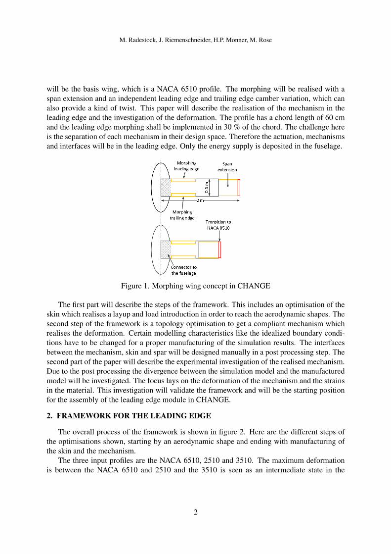
The overall process of the framework is shown in figure 2. Here are the different steps ofthe optimisations shown, starting by an aerodynamic shape and ending with manufacturing ofthe skin and the mechanism.
The three input profiles are the NACA 6510, 2510 and 3510. The maximum deformationis between the NACA 6510 and 2510 and the 3510 is seen as an intermediate state in the
2
M. Radestock, J. Riemenschneider, H.P. Monner, M. Rose
Figure 2. Process Chain of the framework
morphing. Based on the given aerodynamic shapes, the skin optimisation provides a skin layupdistribution with glasfiber reinforced prepreg (GFRP) and ethylene propylene diene monomer(EPDM) rubber, a stringer position as a load interface point for the inner mechanism and themotion path of the stringer due to deformation. The topology optimisation as second step willgive a pre design of an inner kinematic which will be manufactured as compliant mechanism.
2.1 Skin optimisation
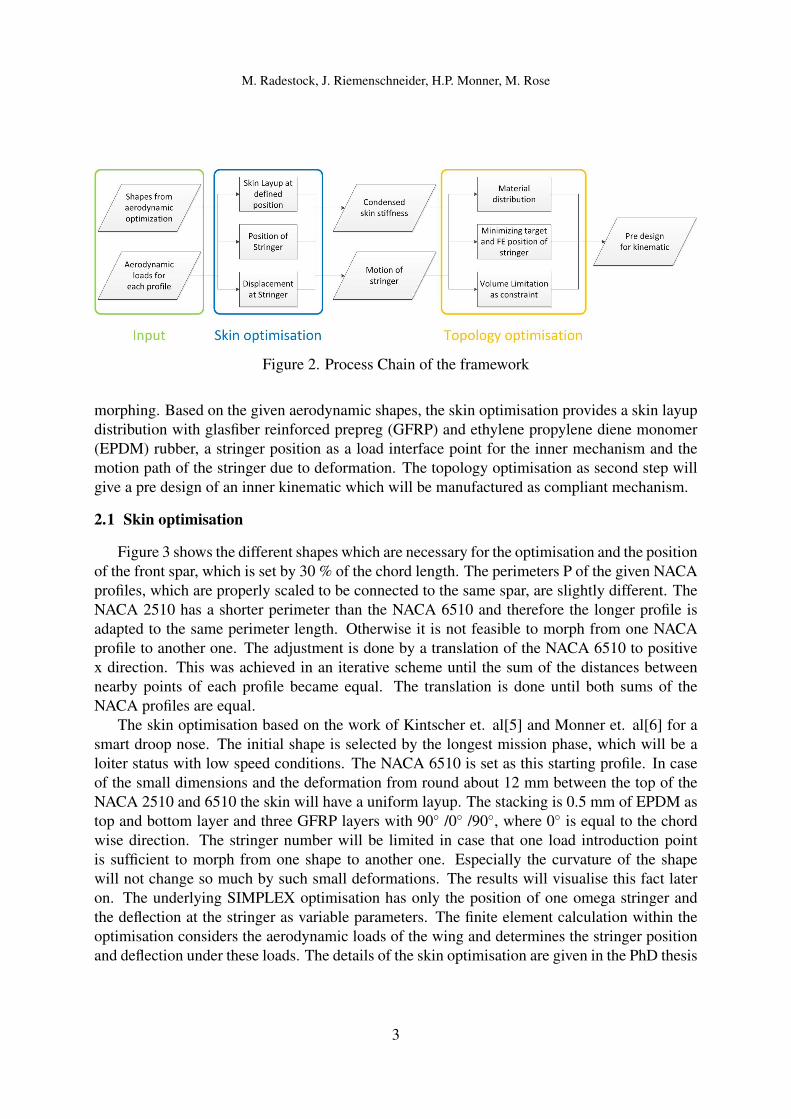
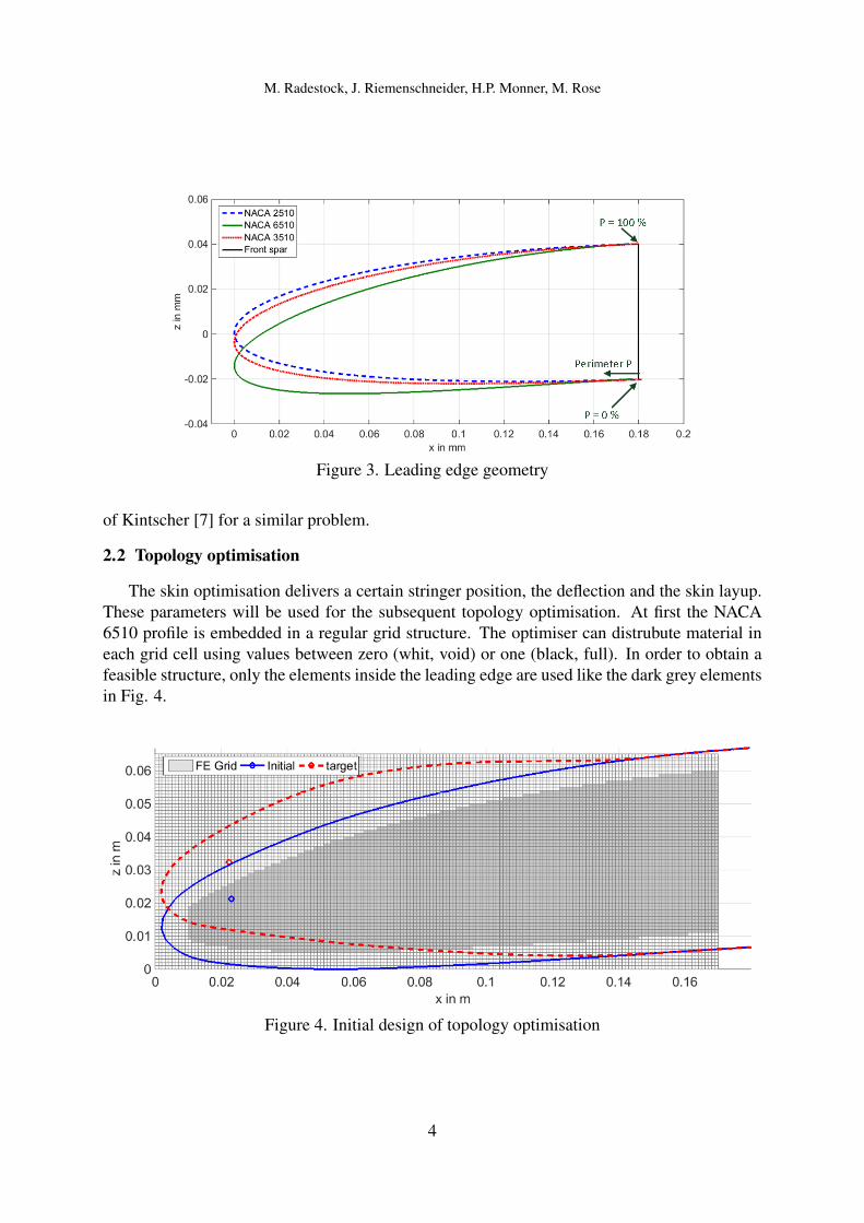
Figure 3 shows the different shapes which are necessary for the optimisation and the positionof the front spar, which is set by 30 % of the chord length. The perimeters P of the given NACAprofiles, which are properly scaled to be connected to the same spar, are slightly different. TheNACA 2510 has a shorter perimeter than the NACA 6510 and therefore the longer profile isadapted to the same perimeter length. Otherwise it is not feasible to morph from one NACAprofile to another one. The adjustment is done by a translation of the NACA 6510 to positivex direction. This was achieved in an iterative scheme until the sum of the distances betweennearby points of each profile became equal. The translation is done until both sums of theNACA profiles are equal.
The skin optimisation based on the work of Kintscher et. al[5] and Monner et. al[6] for asmart droop nose. The initial shape is selected by the longest mission phase, which will be aloiter status with low speed conditions. The NACA 6510 is set as this starting profile. In caseof the small dimensions and the deformation from round about 12 mm between the top of theNACA 2510 and 6510 the skin will have a uniform layup. The stacking is 0.5 mm of EPDM astop and bottom layer and three GFRP layers with 90◦ /0◦ /90◦, where 0◦ is equal to the chordwise direction. The stringer number will be limited in case that one load introduction pointis sufficient to morph from one shape to another one. Especially the curvature of the shapewill not change so much by such small deformations. The results will visualise this fact lateron. The underlying SIMPLEX optimisation has only the position of one omega stringer andthe deflection at the stringer as variable parameters. The finite element calculation within theoptimisation considers the aerodynamic loads of the wing and determines the stringer positionand deflection under these loads. The details of the skin optimisation are given in the PhD thesis
3
M. Radestock, J. Riemenschneider, H.P. Monner, M. Rose
Figure 3. Leading edge geometry
of Kintscher [7] for a similar problem.
2.2 Topology optimisation
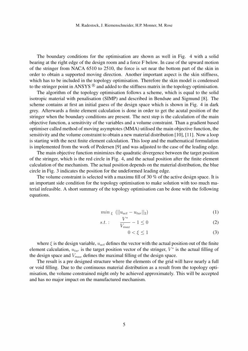
The skin optimisation delivers a certain stringer position, the deflection and the skin layup.These parameters will be used for the subsequent topology optimisation. At first the NACA6510 profile is embedded in a regular grid structure. The optimiser can distrubute material ineach grid cell using values between zero (whit, void) or one (black, full). In order to obtain afeasible structure, only the elements inside the leading edge are used like the dark grey elementsin Fig. 4.
Figure 4. Initial design of topology optimisation
4
M. Radestock, J. Riemenschneider, H.P. Monner, M. Rose
The boundary conditions for the optimisation are shown as well in Fig. 4 with a solidbearing at the right edge of the design room and a force F below. In case of the upward motionof the stringer from NACA 6510 to 2510, the force is set near the bottom part of the skin inorder to obtain a supported moving direction. Another important aspect is the skin stiffness,which has to be included in the topology optimisation. Therefore the skin model is condensedto the stringer point in ANSYS R© and added to the stiffness matrix in the topology optimisation.
The algorithm of the topology optimisation follows a scheme, which is equal to the solidisotropic material with penalisation (SIMP) and described in Bendsøe and Sigmund [8]. Thescheme contains at first an initial guess of the design space which is shown in Fig. 4 in darkgrey. Afterwards a finite element calculation is done in order to get the acutal position of thestringer when the boundary conditions are present. The next step is the calculation of the mainobjective function, a sensitivity of the variables and a volume constraint. Than a gradient basedoptimiser called method of moving asymptotes (MMA) utilised the main objective function, thesensitivity and the volume constraint to obtain a new material distribution [10], [11]. Now a loopis starting with the next finite element calculation. This loop and the mathematical formulationis implemented from the work of Pedersen [9] and was adjusted to the case of the leading edge.
The main objective function minimizes the quadratic divergence between the target positionof the stringer, which is the red circle in Fig. 4, and the actual position after the finite elementcalculation of the mechanism. The actual position depends on the material distribution, the bluecircle in Fig. 3 indicates the position for the undeformed leading edge.
The volume constraint is selected with a maximu fill of 30 % of the active design space. It isan important side condition for the topology optimisation to make solution with too much ma-terial infeasible. A short summary of the topology optimisation can be done with the followingequations.
min ξ (||uact − utar||2) (1)
s.t. :V ∗
Vmax− 1 ≤ 0 (2)
0 < ξ ≤ 1 (3)
where ξ is the design variable, uact defines the vector with the actual position out of the finiteelement calculation, utar is the target position vector of the stringer, V ∗ is the actual filling ofthe design space and Vmax defines the maximal filling of the design space.
The result is a pre designed structure where the elements of the grid will have nearly a fullor void filling. Due to the continuous material distribution as a result from the topology opti-misation, the volume constrained might only be achieved approximately. This will be acceptedand has no major impact on the manufactured mechanism.
5
M. Radestock, J. Riemenschneider, H.P. Monner, M. Rose
2.3 Simulation results
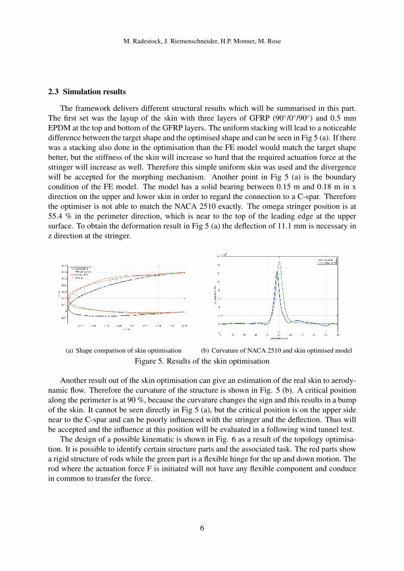
The framework delivers different structural results which will be summarised in this part.The first set was the layup of the skin with three layers of GFRP (90◦/0◦/90◦) and 0.5 mmEPDM at the top and bottom of the GFRP layers. The uniform stacking will lead to a noticeabledifference between the target shape and the optimised shape and can be seen in Fig 5 (a). If therewas a stacking also done in the optimisation than the FE model would match the target shapebetter, but the stiffness of the skin will increase so hard that the required actuation force at thestringer will increase as well. Therefore this simple uniform skin was used and the divergencewill be accepted for the morphing mechanism. Another point in Fig 5 (a) is the boundarycondition of the FE model. The model has a solid bearing between 0.15 m and 0.18 m in xdirection on the upper and lower skin in order to regard the connection to a C-spar. Thereforethe optimiser is not able to match the NACA 2510 exactly. The omega stringer position is at55.4 % in the perimeter direction, which is near to the top of the leading edge at the uppersurface. To obtain the deformation result in Fig 5 (a) the deflection of 11.1 mm is necessary inz direction at the stringer.
(a) Shape comparison of skin optimisation (b) Curvature of NACA 2510 and skin optimised model
Figure 5. Results of the skin optimisation
Another result out of the skin optimisation can give an estimation of the real skin to aerody-namic flow. Therefore the curvature of the structure is shown in Fig. 5 (b). A critical positionalong the perimeter is at 90 %, because the curvature changes the sign and this results in a bumpof the skin. It cannot be seen directly in Fig 5 (a), but the critical position is on the upper sidenear to the C-spar and can be poorly influenced with the stringer and the deflection. Thus willbe accepted and the influence at this position will be evaluated in a following wind tunnel test.
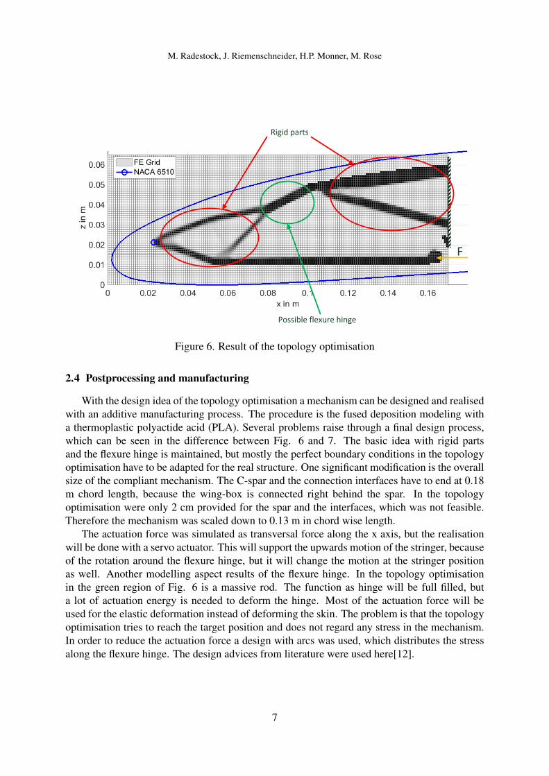
The design of a possible kinematic is shown in Fig. 6 as a result of the topology optimisa-tion. It is possible to identify certain structure parts and the associated task. The red parts showa rigid structure of rods while the green part is a flexible hinge for the up and down motion. Therod where the actuation force F is initiated will not have any flexible component and conducein common to transfer the force.
6
M. Radestock, J. Riemenschneider, H.P. Monner, M. Rose
F
Rigid parts
Possible flexure hinge
Figure 6. Result of the topology optimisation
2.4 Postprocessing and manufacturing
With the design idea of the topology optimisation a mechanism can be designed and realisedwith an additive manufacturing process. The procedure is the fused deposition modeling witha thermoplastic polyactide acid (PLA). Several problems raise through a final design process,which can be seen in the difference between Fig. 6 and 7. The basic idea with rigid partsand the flexure hinge is maintained, but mostly the perfect boundary conditions in the topologyoptimisation have to be adapted for the real structure. One significant modification is the overallsize of the compliant mechanism. The C-spar and the connection interfaces have to end at 0.18m chord length, because the wing-box is connected right behind the spar. In the topologyoptimisation were only 2 cm provided for the spar and the interfaces, which was not feasible.Therefore the mechanism was scaled down to 0.13 m in chord wise length.
The actuation force was simulated as transversal force along the x axis, but the realisationwill be done with a servo actuator. This will support the upwards motion of the stringer, becauseof the rotation around the flexure hinge, but it will change the motion at the stringer positionas well. Another modelling aspect results of the flexure hinge. In the topology optimisationin the green region of Fig. 6 is a massive rod. The function as hinge will be full filled, buta lot of actuation energy is needed to deform the hinge. Most of the actuation force will beused for the elastic deformation instead of deforming the skin. The problem is that the topologyoptimisation tries to reach the target position and does not regard any stress in the mechanism.In order to reduce the actuation force a design with arcs was used, which distributes the stressalong the flexure hinge. The design advices from literature were used here[12].
7
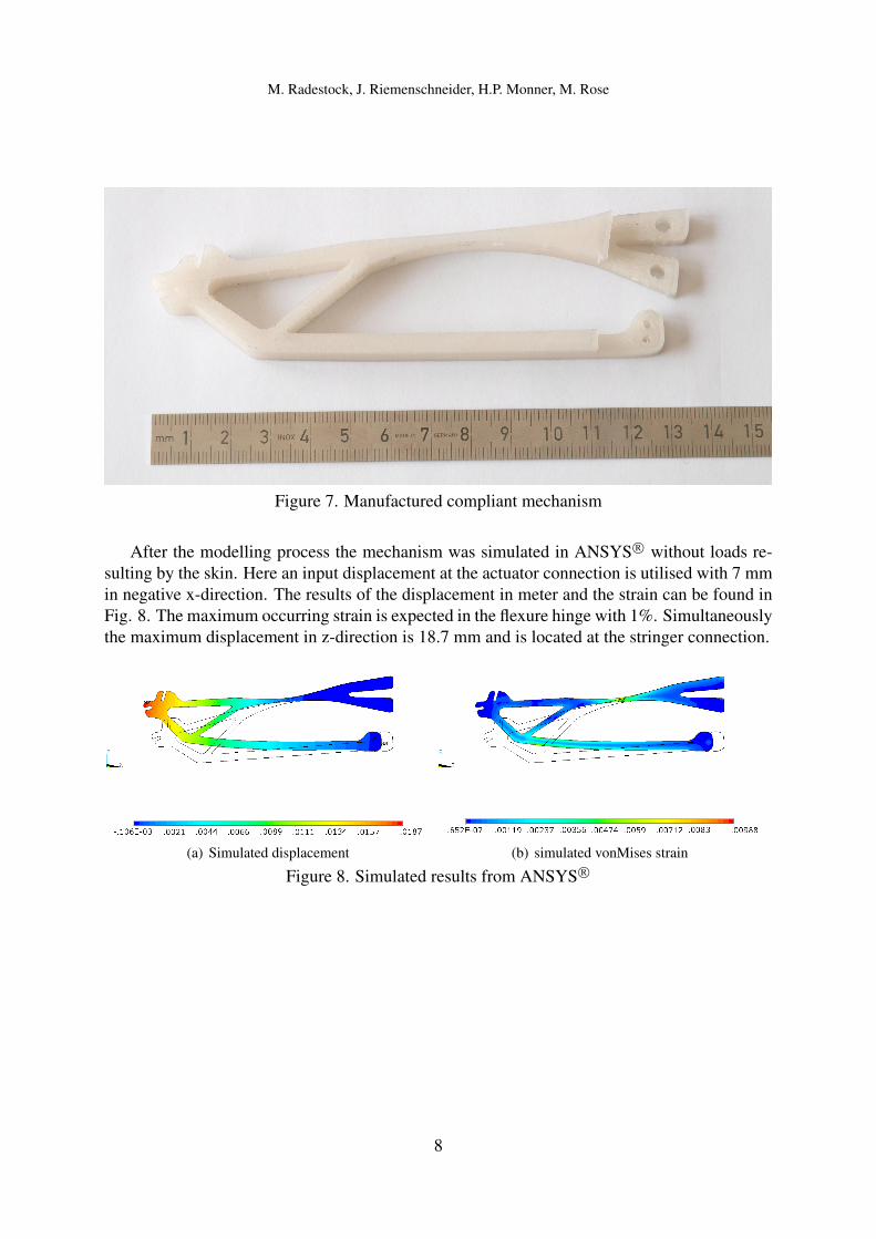
M. Radestock, J. Riemenschneider, H.P. Monner, M. Rose
Figure 7. Manufactured compliant mechanism
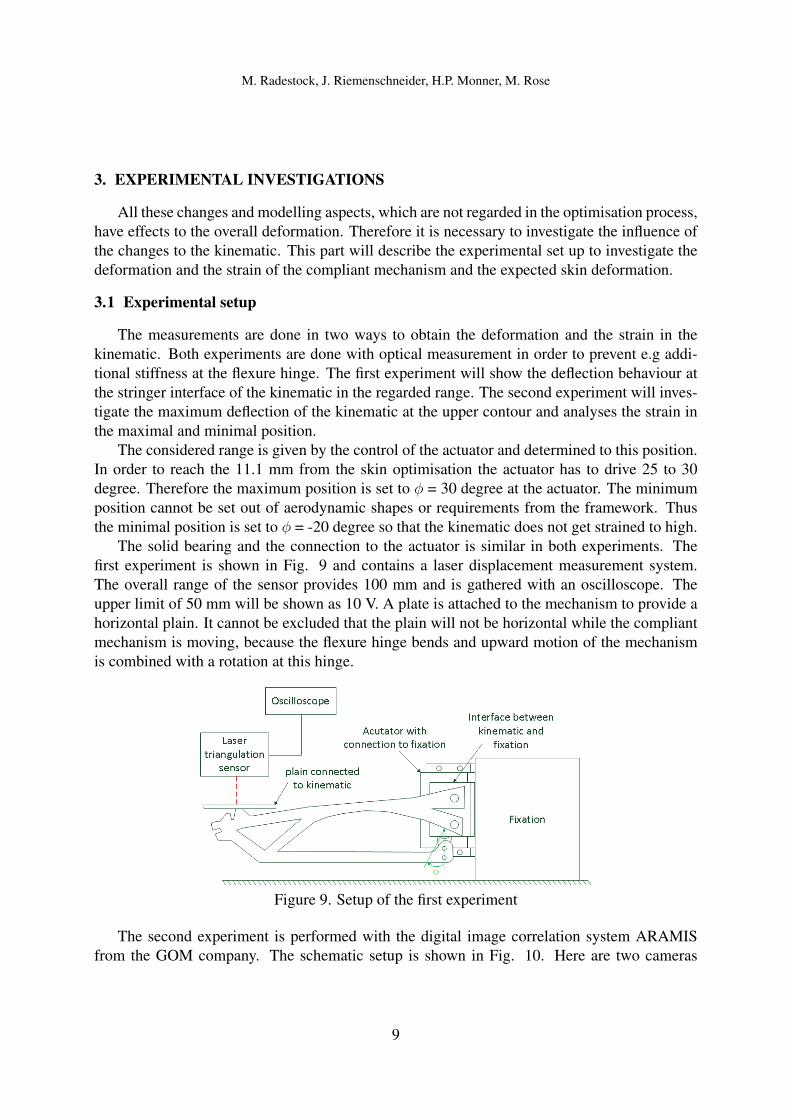
After the modelling process the mechanism was simulated in ANSYS R© without loads re-sulting by the skin. Here an input displacement at the actuator connection is utilised with 7 mmin negative x-direction. The results of the displacement in meter and the strain can be found inFig. 8. The maximum occurring strain is expected in the flexure hinge with 1%. Simultaneouslythe maximum displacement in z-direction is 18.7 mm and is located at the stringer connection.
(a) Simulated displacement (b) simulated vonMises strain
Figure 8. Simulated results from ANSYS R©
8
M. Radestock, J. Riemenschneider, H.P. Monner, M. Rose
3. EXPERIMENTAL INVESTIGATIONS
All these changes and modelling aspects, which are not regarded in the optimisation process,have effects to the overall deformation. Therefore it is necessary to investigate the influence ofthe changes to the kinematic. This part will describe the experimental set up to investigate thedeformation and the strain of the compliant mechanism and the expected skin deformation.
3.1 Experimental setup
The measurements are done in two ways to obtain the deformation and the strain in thekinematic. Both experiments are done with optical measurement in order to prevent e.g addi-tional stiffness at the flexure hinge. The first experiment will show the deflection behaviour atthe stringer interface of the kinematic in the regarded range. The second experiment will inves-tigate the maximum deflection of the kinematic at the upper contour and analyses the strain inthe maximal and minimal position.
The considered range is given by the control of the actuator and determined to this position.In order to reach the 11.1 mm from the skin optimisation the actuator has to drive 25 to 30degree. Therefore the maximum position is set to φ = 30 degree at the actuator. The minimumposition cannot be set out of aerodynamic shapes or requirements from the framework. Thusthe minimal position is set to φ = -20 degree so that the kinematic does not get strained to high.
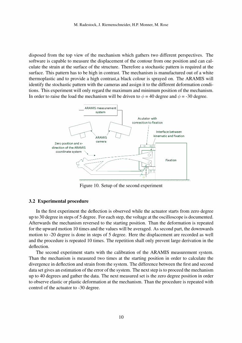
The solid bearing and the connection to the actuator is similar in both experiments. Thefirst experiment is shown in Fig. 9 and contains a laser displacement measurement system.The overall range of the sensor provides 100 mm and is gathered with an oscilloscope. Theupper limit of 50 mm will be shown as 10 V. A plate is attached to the mechanism to provide ahorizontal plain. It cannot be excluded that the plain will not be horizontal while the compliantmechanism is moving, because the flexure hinge bends and upward motion of the mechanismis combined with a rotation at this hinge.
Figure 9. Setup of the first experiment
The second experiment is performed with the digital image correlation system ARAMISfrom the GOM company. The schematic setup is shown in Fig. 10. Here are two cameras
9
M. Radestock, J. Riemenschneider, H.P. Monner, M. Rose
disposed from the top view of the mechanism which gathers two different perspectives. Thesoftware is capable to measure the displacement of the contour from one position and can cal-culate the strain at the surface of the structure. Therefore a stochastic pattern is required at thesurface. This pattern has to be high in contrast. The mechanism is manufactured out of a whitethermoplastic and to provide a high contrast,a black colour is sprayed on. The ARAMIS willidentify the stochastic pattern with the cameras and assign it to the different deformation condi-tions. This experiment will only regard the maximum and minimum position of the mechanism.In order to raise the load the mechanism will be driven to φ = 40 degree and φ = -30 degree.
Figure 10. Setup of the second experiment
3.2 Experimental procedure
In the first experiment the deflection is observed while the actuator starts from zero degreeup to 30 degree in steps of 5 degree. For each step, the voltage at the oscilloscope is documented.Afterwards the mechanism reversed to the starting position. Than the deformation is repeatedfor the upward motion 10 times and the values will be averaged. As second part, the downwardsmotion to -20 degree is done in steps of 5 degree. Here the displacement are recorded as welland the procedure is repeated 10 times. The repetition shall only prevent large derivation in thedeflection.
The second experiment starts with the calibration of the ARAMIS measurement system.Than the mechanism is measured two times at the starting position in order to calculate thedivergence in deflection and strain from the system. The difference between the first and seconddata set gives an estimation of the error of the system. The next step is to proceed the mechanismup to 40 degrees and gather the data. The next measured set is the zero degree position in orderto observe elastic or plastic deformation at the mechanism. Than the procedure is repeated withcontrol of the actuator to -30 degree.
10
M. Radestock, J. Riemenschneider, H.P. Monner, M. Rose
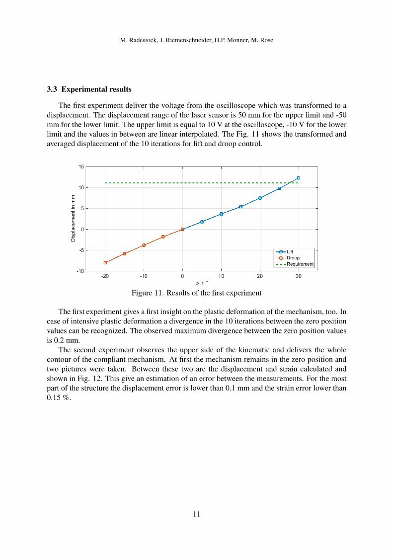
3.3 Experimental results
The first experiment deliver the voltage from the oscilloscope which was transformed to adisplacement. The displacement range of the laser sensor is 50 mm for the upper limit and -50mm for the lower limit. The upper limit is equal to 10 V at the oscilloscope, -10 V for the lowerlimit and the values in between are linear interpolated. The Fig. 11 shows the transformed andaveraged displacement of the 10 iterations for lift and droop control.
Figure 11. Results of the first experiment
The first experiment gives a first insight on the plastic deformation of the mechanism, too. Incase of intensive plastic deformation a divergence in the 10 iterations between the zero positionvalues can be recognized. The observed maximum divergence between the zero position valuesis 0.2 mm.
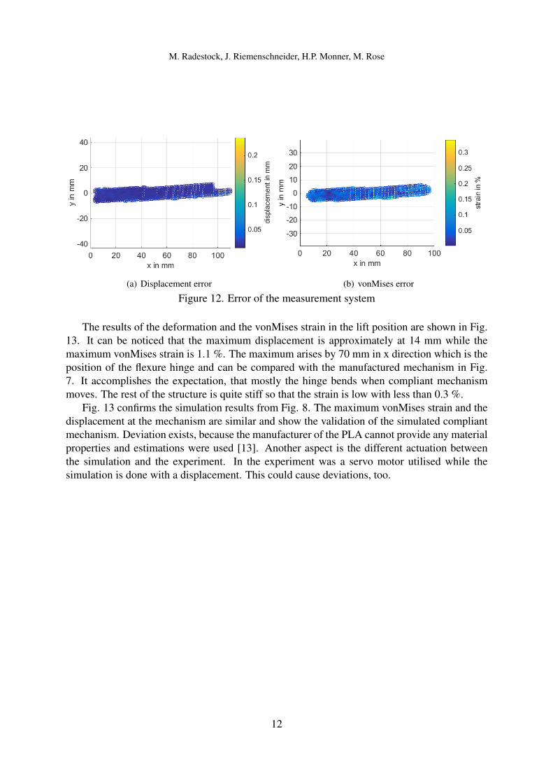
The second experiment observes the upper side of the kinematic and delivers the wholecontour of the compliant mechanism. At first the mechanism remains in the zero position andtwo pictures were taken. Between these two are the displacement and strain calculated andshown in Fig. 12. This give an estimation of an error between the measurements. For the mostpart of the structure the displacement error is lower than 0.1 mm and the strain error lower than0.15 %.
11
M. Radestock, J. Riemenschneider, H.P. Monner, M. Rose
(a) Displacement error (b) vonMises error
Figure 12. Error of the measurement system
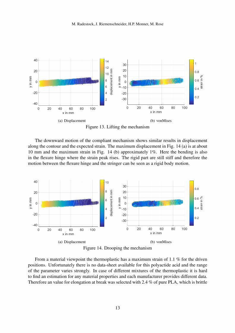
The results of the deformation and the vonMises strain in the lift position are shown in Fig.13. It can be noticed that the maximum displacement is approximately at 14 mm while themaximum vonMises strain is 1.1 %. The maximum arises by 70 mm in x direction which is theposition of the flexure hinge and can be compared with the manufactured mechanism in Fig.7. It accomplishes the expectation, that mostly the hinge bends when compliant mechanismmoves. The rest of the structure is quite stiff so that the strain is low with less than 0.3 %.
Fig. 13 confirms the simulation results from Fig. 8. The maximum vonMises strain and thedisplacement at the mechanism are similar and show the validation of the simulated compliantmechanism. Deviation exists, because the manufacturer of the PLA cannot provide any materialproperties and estimations were used [13]. Another aspect is the different actuation betweenthe simulation and the experiment. In the experiment was a servo motor utilised while thesimulation is done with a displacement. This could cause deviations, too.
12
M. Radestock, J. Riemenschneider, H.P. Monner, M. Rose
(a) Displacement (b) vonMises
Figure 13. Lifting the mechanism
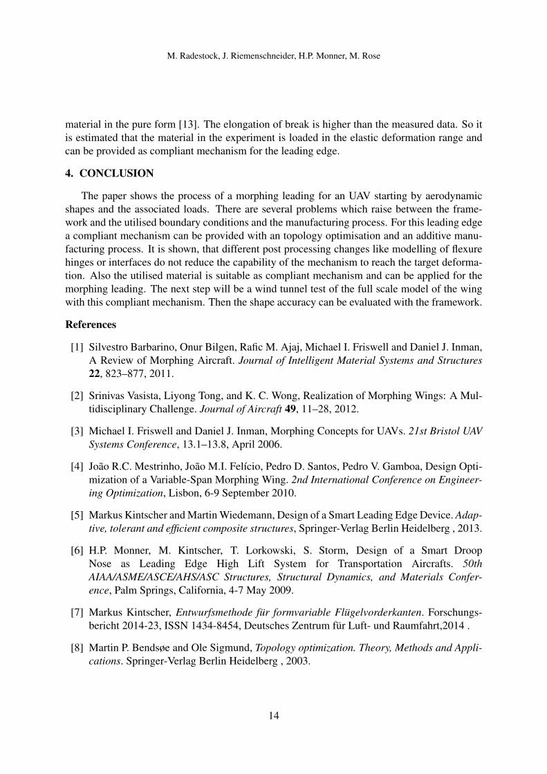
The downward motion of the compliant mechanism shows similar results in displacementalong the contour and the expected strain. The maximum displacement in Fig. 14 (a) is at about10 mm and the maximum strain in Fig. 14 (b) approximately 1%. Here the bending is alsoin the flexure hinge where the strain peak rises. The rigid part are still stiff and therefore themotion between the flexure hinge and the stringer can be seen as a rigid body motion.
(a) Displacement (b) vonMises
Figure 14. Drooping the mechanism
From a material viewpoint the thermoplastic has a maximum strain of 1.1 % for the drivenpositions. Unfortunately there is no data-sheet available for this polyactide acid and the rangeof the parameter varies strongly. In case of different mixtures of the thermoplastic it is hardto find an estimation for any material properties and each manufacturer provides different data.Therefore an value for elongation at break was selected with 2.4 % of pure PLA, which is brittle
13
M. Radestock, J. Riemenschneider, H.P. Monner, M. Rose
material in the pure form [13]. The elongation of break is higher than the measured data. So itis estimated that the material in the experiment is loaded in the elastic deformation range andcan be provided as compliant mechanism for the leading edge.
4. CONCLUSION
The paper shows the process of a morphing leading for an UAV starting by aerodynamicshapes and the associated loads. There are several problems which raise between the frame-work and the utilised boundary conditions and the manufacturing process. For this leading edgea compliant mechanism can be provided with an topology optimisation and an additive manu-facturing process. It is shown, that different post processing changes like modelling of flexurehinges or interfaces do not reduce the capability of the mechanism to reach the target deforma-tion. Also the utilised material is suitable as compliant mechanism and can be applied for themorphing leading. The next step will be a wind tunnel test of the full scale model of the wingwith this compliant mechanism. Then the shape accuracy can be evaluated with the framework.
References
[1] Silvestro Barbarino, Onur Bilgen, Rafic M. Ajaj, Michael I. Friswell and Daniel J. Inman,A Review of Morphing Aircraft. Journal of Intelligent Material Systems and Structures22, 823–877, 2011.
[2] Srinivas Vasista, Liyong Tong, and K. C. Wong, Realization of Morphing Wings: A Mul-tidisciplinary Challenge. Journal of Aircraft 49, 11–28, 2012.
[3] Michael I. Friswell and Daniel J. Inman, Morphing Concepts for UAVs. 21st Bristol UAVSystems Conference, 13.1–13.8, April 2006.
[4] João R.C. Mestrinho, João M.I. Felício, Pedro D. Santos, Pedro V. Gamboa, Design Opti-mization of a Variable-Span Morphing Wing. 2nd International Conference on Engineer-ing Optimization, Lisbon, 6-9 September 2010.
[5] Markus Kintscher and Martin Wiedemann, Design of a Smart Leading Edge Device. Adap-tive, tolerant and efficient composite structures, Springer-Verlag Berlin Heidelberg , 2013.
[6] H.P. Monner, M. Kintscher, T. Lorkowski, S. Storm, Design of a Smart DroopNose as Leading Edge High Lift System for Transportation Aircrafts. 50thAIAA/ASME/ASCE/AHS/ASC Structures, Structural Dynamics, and Materials Confer-ence, Palm Springs, California, 4-7 May 2009.
[7] Markus Kintscher, Entwurfsmethode für formvariable Flügelvorderkanten. Forschungs-bericht 2014-23, ISSN 1434-8454, Deutsches Zentrum für Luft- und Raumfahrt,2014 .
[8] Martin P. Bendsøe and Ole Sigmund, Topology optimization. Theory, Methods and Appli-cations. Springer-Verlag Berlin Heidelberg , 2003.
14
M. Radestock, J. Riemenschneider, H.P. Monner, M. Rose
[9] Claus B. W. Pedersen, Thomas Buhl and Ole Sigmund, Topology synthesis of large-displacement compliant mechanisms. International Journal for Numerical Methods in En-gineering 50, 2683–2705, 2001.
[10] Krister Svanberg, The method of moving asymptotes: A new method for structural op-timization. International Journal for Numerical Methods in Engineering 24, 359–373,1987.
[11] Krister Svanberg, Some modelling aspects for the MATLAB implementation of MMA.Internal publication of the KTH. Devision Optimization and Systems Theory, September2004.
[12] Nicolae Lobontiu, Compliant Mechanisms: Design of Flexure Hinges. CRC Press LLCLondon, New York, 2003.
[13] Aji P. Mathew, Kristiina Oksman and Mohini Sain, Mechanical Properties of Biodegrad-able Composites from Poly Lactic Acid (PLA) and Microcrystalline Cellulose (MCC).Journal of Applied Polymer Science 97, 2014–2025, 2005.
15