Embed Size (px)
Citation preview

Experimental Investigation of Self-Centering Steel Plate Shear Walls
Patricia M. Clayton1, Daniel M. Dowden2, Tyler Winkley3, Jeffrey W. Berman4, Michel Bruneau5, Laura N. Lowes6
1 Research Assistant, Dept. of Civil and Environmental Engineering, University of Washington, Seattle, WA 98195; Email: [email protected] 2 Research Assistant, Dept. of Civil, Structural and Environmental Engineering, University at Buffalo, Buffalo, NY 14260; Email: [email protected] 3Research Assistant, Dept. of Civil and Environmental Engineering, University of Washington, Seattle, WA 98195; Email: [email protected] 4Assistant Professor, Dept. of Civil and Environmental Engineering, University of Washington, Seattle, WA 98195; PH: (206)616-3530; E-mail: [email protected] 5Professor, Dept. of Civil, Structural and Environmental Engineering, University at Buffalo, Buffalo, NY 14260; PH: (716) 645-3398; Email: [email protected] 6Associate Professor, Dept. of Civil and Environmental Engineering, University of Washington, Seattle, WA 98195; PH: (206)685-2563; E-mail: [email protected] ABSTRACT
A self-centering steel plate shear wall (SC-SPSW) system has been developed to achieve enhanced performance objectives following earthquakes, including recentering. The SC-SPSW consists of thin steel infill web panels as the primary lateral load resistance and energy dissipation of the system providing a high initial stiffness, where the moment resisting connections of conventional SPSW construction are replaced with post-tensioned (PT) beam-to-column connections that allow the beam to rock about its flanges to provide system recentering.
The system and component behavior of SC-SPSWs have been investigated experimentally through a series of quasi-static and shake table tests. Quasi-static subassembly tests at the University of Washington have been conducted to study the effects of various design parameters on overall cyclic response and component demands. The University at Buffalo experiments focus on third-scale 3-story SC-SPSWs subjected to quasi-static and shake table testing to investigate system behavior. These experiments consider three different PT rocking connection details: 1) connections that rock about the beam flanges, 2) connections that rock about the beam centerline, and 3) an innovative NewZ-BREAKSS connection that rocks about the top beam flange only. The latter two PT connections have been proposed as methods to essentially eliminate floor system damage due to frame expansion that occurs with typical PT connections where the beams rock about their flanges.
1586Structures Congress 2012 © ASCE 2012

INTStesteesignwebyielunlcenwal
A ncombeatenconandverPT ultifoll
SCIn t
prc
nedes
TRODUCTel plate sheel infill platenificant strenb plates prolding in the oaded after
ntering technll to essentia
new self-cenmbining steeam-to-columsioning in t
nnection rotad with proprtical bounda
elongation pimately redulowing an ea
-SPSW BEHthis researchrovide the re
connection tyew system, ascribed by su
Figure 1. Sconnec
TION ar walls (SPes, referred tngth and stifovide energydirection of yielding m
nologies, sucally zero disp
ntering SPSel web plate
mn connectiothe connectiates relative er detailing
ary elementsprovides the
uces the costarthquake.
HAVIOR h, three differecentering caype is discusa simple appruperimposin
chematics oction in its (
PSWs) are lto as web plffness througy dissipationf the tension
makes the SPch that smalplacement af
SW (SC-SPSes with a stons (Dowdenions is desito the colum the beams
s (HBEs ande restoring fots of repair a
rent PT HBEapabilities ofssed below. Froximation o
ng the respon
of (a) SC-SP(b) undeform
lateral forcelates, withingh the develn and substafield. The lo
PSW systemller restoringfter a seismic
SW) systemteel boundarn et at. 2012igned to remmn during la and colum
d VBEs), resporces necessand provides
E-to-VBE cof the SC-SPSFor purposesof the cyclicnse of the tw
PSW and flamed and (c)
e resisting syn a steel bouopment of teantial ductilow stiffness
m ideal for bg forces arec event.
m (Fig. 1) hry frame wi2, Clayton emain elasticateral drift ofmns, referred
pectively, resary to recens a more rap
onnections aSW system. s of general
c behavior ofwo key comp
ange rockin) deformed
ystems that undary frameension field lity through of thin web
being pairede required to
has been deith post-tenset al. 2012)
c and elongf the buildind to as horemain undamnter the buildpid return to
are being invThe behaviounderstandi
f the SC-SPSonents of th
ng PT HBE-
configurati
utilize thin e to provide action. The distributed
plate when d with self-o return the
veloped by sioned (PT) ). The post-gates as the ng (Fig. 1c), izontal and
maged. This ding, which
o occupancy
vestigated to or of each ng of this SW can be e system—
to-VBE on.
1587Structures Congress 2012 © ASCE 2012

the pincomsecelasflag
PTThein Fwita ggaprotaconnon
As apacarediapdiapresuChr
In framTheconNotthe Sindecelassho
Fig
web plates ched, tensio
mplex than tions with rstic cyclic rg-shaped hys
HBE-to-VBe conventionFig. 1c. Durh a stiffnessap forms in
p opens andational stiffnnnection retunlinear elasti
a gap formsart, a phenomeful detailinphragm sysphragm detault in very ristopoulos 2
this researchme expansioe first of thnnection, thete that the Pnet elongat
nce the gap icompression stic and doe
own in Fig. 2
gure 2. Idea
and the PTon-only cycl
this idealizrespect to Sresponse of steresis (Fig
BE Connectnal PT connering lateral s equivalent t
the connectd the PT strness. If theurns along tic response s
s in the flangmenon referng, this framtem. Additiailing, the rlarge axial
2008).
h, two new on while stillese proposee HBE-to-VBPT strands mtion of the Pin the conneas with the
s not fully re2b.
alized cyclic
T boundary flic response zation, and SC-SPSW exthe PT fram. 2c) that is c
tions ection as sholoading, theto that of a ftion, referredrands elong PT connecthe same bishown for th
ge rocking Prred to as fra
me expansiononally, if frrestraint to
demands o
PT connecl maintaining
ed connectioBE joint roc
must be termPT needed tection is pre flange rockelax, the con
c behavior o
frame (Fig. (Fig. 2a); a
these key dxperimental
me (Fig. 2b)characteristi
own in Fig. 1e moment defully weldedd to as the date, the conction and itlinear path
he flange roc
T connectioame expansin can result frame expancolumns sp
on the HBE
ction details g the recente
ons is showncks about a
minated alongto generate sent in its in
king PT connnnection resp
of (a) web pl
2). The ideactual web differences results. Th
), discussed ic of self-cen
1b rocks aboemand in th
d moment-redecompressionnection rests componenduring unloking PT fram
n, the columion (Garlockin significa
nsion is not preading proE (Garlock
have been ering capabin schematic
pin at the g the length recentering
nitial confignection, as lponds in a li
late, (b) PT
ealized web plate behavare discuss
his is couplebelow, to p
ntering syste
out its flangehe connectioesisting connon moment, sponds withnts remain oading, resume in Fig. 2b
mns are forcek et al. 2007
ant damage taccommod
ovided by thet al. 2007
proposed tilities of the ally in Fig. centerline oof the HBEforces wou
guration and long as the inear, elastic
frame, (c) S
plate has a ior is more
sed in later ed with the produce the ems.
es as shown on increases nection until
Md. As the h a reduced
elastic, the lting in the b.
ed to spread 7). Without to the floor
dated in the he slab can 7, Kim and
o eliminate SC-SPSW. 3a. In this
of the HBE. E, otherwise uld be zero.
there is no PT remains c manner as
SC-SPSW.
1588Structures Congress 2012 © ASCE 2012
F
SimNewis srocthualonelemcon
UN
LarWabettintevaliutil
Tes
A ssetuHBpossubheig
Frarollimpits bVBleve
Figure 3. (a)
milarly, a new Zealand hschematicallks about thes mitigatingng the lengtments remainnection, this
NIVERSITY
rge-scale SCashington. Thter understaeraction of tidate numerlized the flan
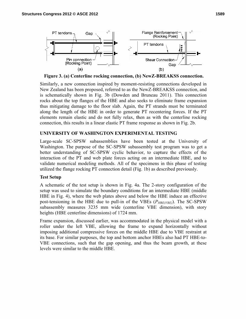
st Setup
schematic ofup was used
BE in Fig. 4)st-tensioningbassembly mghts (HBE c
ame expansioler under thposing additbase. For sim
BE connectioels were sim
) Centerline
w connectiohas been proply shown ine top flangesg damage to th of the HBin elastic ans results in a
Y OF WASH
C-SPSW suhe purpose
anding of Sthe PT and rical modelinnge rocking P
f the test sed to simulate), where the g in the HBEmeasures 32centerline dim
on, discussehe left VBtional comprmilar purposons, such th
milar to the m
e rocking co
on inspired bposed, referr
n Fig. 3b (Ds of the HBEthe floor sl
BE in ordernd do not fua linear elasti
HINGTON E
ubassemblieof the SC-S
SC-SPSW cyweb plate f
ng methods.PT connecti
tup is showthe boundarweb plates
E due to pu235 mm wimensions) o
d earlier, waE, allowingressive forceses, the top ahat the gap middle HBE.
nnection, (b
by moment-red to as the Dowden andE and also slab. Again, tr to generateully relax, thic PT frame
EXPERIME
es have beSPSW subasyclic behavforces acting. All of the on detail (Fi
wn in Fig. 4ary conditionabove and b
ull-in of the ide (centerlf 1724 mm.
as accommog the framees on the miand bottom aopening, an
b) NewZ-BR
-resisting conNewZ-BRE
d Bruneau 2seeks to elimthe PT strane PT recenthen as with response as
ENTAL TE
een tested ssembly testior, to captg on an intespecimens i
ig. 1b) as de
a. The 2-stons for an intebelow the H
VBEs (PHBline VBE d
odated in thee to expandiddle HBE danchor HBE
nd thus the
REAKSS co
nnections deEAKSS conn2011). This minate framends must betering forcesh the centerl shown in Fi
ESTING at the Un
t program wture the effermediate Hin this phasscribed prev
ry configuraermediate HB
HBE induce aBE(VBE)). Thedimension),
e physical md horizontaldue to VBE Es also had Pbeam growt
onnection.
eveloped in nection, and
connection e expansion terminated
s. If the PT ine rocking ig. 2b.
niversity of was to get a fects of the
HBE, and to e of testing
viously.
ation of the BE (middle an effective
e SC-SPSW with story
model with a lly without restraint at
PT HBE-to-th, at these
f
1589Structures Congress 2012 © ASCE 2012
Shesheconagadecloca
ThedurmmTheMPrespboufishrepwelaffe(20
Spe
ThePT the confollfollAllexccon
(a) Sche
ear forces aear tab connennection rotaainst local dacompressionalized dama
e boundary fring testing sm diameter Ge web platesPa and 240 pectively. Inundary elemhplate connelaced followlded web plaects specime
011).
ecimen Desc
e test prograforce at eaceffects of
nvention for lowed by thlowed by the specimens
ception of Spnnection as in
matic of tes
Figure 4.t the PT HBections. Lonation. The Hamage due t. Also, cornge in the pla
frame elemeso that they Grade 270 se were of ASMPa for th
n all but onements via a ection allowwing each teate-to-fish pen behavior.
criptions
am (Table 1)ch HBE, To,
web plate the test spe
he initial tote web plate s utilized thpecimen 8s1ndicated by
st setup
. UW SC-SPBE-to-VBE
ng slotted boHBE flangesto the large ner cutouts ate as a gap f
nts were of Acould be reueven-wire st
STM A1008he 20 and 1e of the spe
bolted fishwed for the y
est. One spplate connect Further det
) included vaand numberand PT co
ecimens is thtal PT forcegage thicknhe bolted
10k20GaW, the “W” add
(b)
PSW subassconnections
lt holes wers at the conncompressivewere provi
forms in the
A992 steel aused for multrand with resteel with yi16 gage placimens, the hplate connyielded webecimen wastion to comptails on the t
ariations in tr of PT strannnection strhe number oe at each HBness or thicknweb plate-twhich utiliz
ded to the sp
) Specimen
sembly test s were tran
re used in thnections were forces actided in the connection.
and were desltiple tests. Teusable barrield strengthates (0.92mm
web platesnection. Theb plates to bs tested withpare how thtest setup ca
the web platnds in each crength and of PT strandBE in units
knesses (e.g. to-fishplate zed a weldedpecimen nam
before testi
setup sferred thro
he shear tab tre reinforceding on the flweb plates
signed to remThe PT stranrel anchors ahs of approxim and 1.52were conne
e bolted webe easily reh a more co
he web plate an be found
te thicknesseconnection, Nstiffness. T
ds per HBE of kips (e.“16Ga"), if connection
d web plate-me.
ng
ough slotted to allow for d to protect
flanges after to prevent
main elastic nds were 13 at each end. imately 180
2mm thick), ected to the eb plate-to-emoved and onventional connection in Winkley
es, tw, initial Ns, to study
The naming (e.g. “8s"), g. “100k"),
f applicable.n, with the -to-fishplate
1590Structures Congress 2012 © ASCE 2012
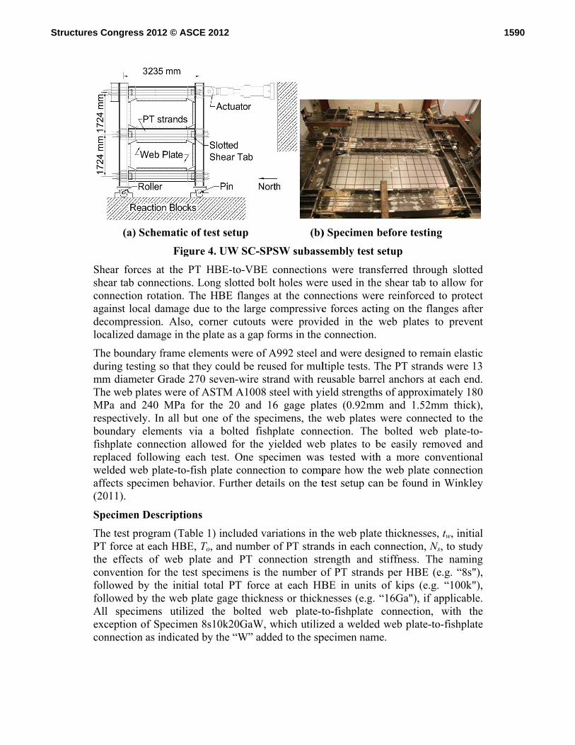
Table 1. SC-SPSW subassembly specimens
Specimen Name Ns To
(kN) tw(mm) Web plate-to-fish
plate conn. type Load
protocol 1st story 2nd story 8s100k 8 445 -- -- Bolted LP-BF 6s75k 6 334 -- -- Bolted LP-BF
8s100k20Ga 8 445 0.92 0.92 Bolted LP1 8s100k16Ga 8 445 1.52 1.52 Bolted LP1 6s75k20Ga 6 334 0.92 0.92 Bolted LP1 6s75k16Ga 6 334 1.52 1.52 Bolted LP1
8s100k20Ga-2 8 445 0.92 0.92 Bolted LP2 8s100k16Ga20Ga 8 445 1.52 0.92 Bolted LP2
8s100k20GaW 8 445 0.92 0.92 Welded LP2
Instrumentation and Displacement History Instrumentation was installed on the specimen to measure applied loads, global displacements, gap rotations, PT forces, and HBE and VBE strains. The cyclic displacement history for the tests (LP1) were a modification of ATC-24 (ATC 1992), similar to the history used in previous SPSW experiments by Vian et al. (2009). An alternate load protocol (LP2) was used for some of the later tests, as indicated in Table 1. This load protocol had fewer cycles at small drift levels. Since the specimens without web plates (8s100k and 6s75k) were expected to remain elastic during the entire test, a simplified load protocol (LP-BF) was used consisting of two cycles each at target peak drifts of 0.5%, 1%, and 2% and one cycle at 3% drift.
Experimental Results and Observations
Comparison of web plate thicknesses
As shown in Fig. 5, for specimens with the same number of PT strands and initial PT force, an increase in web plate thickness results in a proportional increase in specimen strength and energy dissipation as expected. When comparing the unloading portion of the hysteretic responses shown in Fig. 5, specimens with web plates (6s75k20Ga and 6s75k16Ga) have additional hysteresis below the unloading portion of the bare PT frame (6s75k) response. This additional hysteresis suggests that the web plate has some compressive strength that is not accounted for in the idealized tension-only behavior assumed in Fig. 2. This compressive strength increases as the web plate thickness increases, ranging from 10-20% of the web plate tension field strength (Clayton et al. 2011). Further research is being done to understand and better quantify this characteristic of web plate behavior. This additional hysteresis in the web plate during unloading also provides some resistance to recentering as suggested by the increase in residual drift at zero-load as the web plate thickness increases; however, with the exception of the negative loading direction of Specimen 6s75k16Ga, the specimen with the thickest web plates and lowest PT connection strength and stiffness, all test specimens were able to recenter with residual drifts less than 0.2% at zero-load (Clayton et al. 2011).
1591Structures Congress 2012 © ASCE 2012

Com
Figplatexpprodue(Cl
Com
Theconat tbetwbucdurwebof tthe of ta loearldemwel
Figure 5. C
mparison of
g. 6 shows ate thickness
pected, an inoportional ine to the incayton et al. 2
mparison of
e typical fannections wathe bottom ween 2.5 tockling of thering cyclic lob plate-to-fisthe VBEs inweld near th
the heat affeower strengtlier onset o
mands; howelded specime
Figu
Comparison
f PT connecti
a comparisonses but diffncrease in thncrease in thcrease in ro2011, 2012)
f web plate-to
ailure modeas tearing ofof the first o 3% drift. e web plate oading. Howshplate connn both storiehe rocking Pcted zone ofth capacity, f strength dever, due toen did have
ure 6. Comp
n of specime
ion designs
n of the resferent numbhe total croshe recenterinotational sti.
o-fishplate c
e of specimf the web pla
story (Fig. This tearin
at this locatwever, at thenection had tes (Fig. 7b). PT HBE-to-Vf the weld. Tapproximate
degradation o the slowera larger drift
parison of sp
ens with dif
sponses of tber of PT ss-sectional ng stiffness oiffness of th
connection ty
mens with ate along the7a). Tearin
ng is believtion as the te end of testtearing of thInitial tearin
VBE connecThe welded sely 85% of due to the r propagatioft ductility.
pecimens wi
fferent web
two specimestrands andarea of the of the specihe decompr
ypes
the bolted e entire leng
ng was typicved to be dutension fieldting, the spehe web plateng was first
ction and tearspecimen (8sthe bolted sinitiation of
on of tearing
ith different
plate thickn
ens with thed initial PTPT strands
imen duringressed PT c
web plate-gth of the clcally initiall
due to the od formed andecimen with e along the et observed aring propagas100k20GaWspecimen caf tearing at g along the
t PT design
nesses.
e same web T force. As
results in a g unloading, connections
-to-fishplate lamping bar ly observed out-of-plane d re-formed the welded
entire length at the toe of ated outside W) did have apacity, and
lower drift HBEs, the
ns
f
1592Structures Congress 2012 © ASCE 2012

FigHB
Com
AnaOpeandsprimatAISmatmatas moof t
Figthe mat2%tenandresemet
AlsspealteFurdurrelaexp
gure 7. WebBE at 4% d
mparison wi
alytical nonenSees (Maz
d the rockining elementsterial was m
SC Design Gterial couplterial with asuggested bdeled to havthe actual we
g. 8 shows coOpenSees (
terials. The % drift dema
sion-and-comd reloading pearch is beinthods of mod
so both Openecimen. Thisernating direrther researcring cyclic, atively simpperimental re
(a) b plate tearirift and (b)
ith analytica
nlinear finitezzoni et al. 2g PT connes as describe
modeled usinGuide 20 (Sled in paraa compressivby the expeve a backboneb plate mat
omparison o(OS) modelsOpenSees m
ands for purmpression stpath of the eng done to bdeling this p
nSees mode is believed ections of thch is also be
bi-directionple OpenSeesponse.
ing along (awelded web
al models
e element m2006). The wections wereed in Claytonng the idealizSabelli and Ballel with ave strength erimental resne curve thaerial.
f the experims using the t
models shownrposes of cotrip materialexperimentabetter quant
phenomenon
els underestimto be due to he tension-fing done to
nal yieldingees analytic
a) bolted web plate conn
models of thweb plates we modeled un et al. (201zed tension-Bruneau 200an elastic-peequivalent tosults. Both at matched t
mental respoension-only n here were
omparison. Tl appears to al hysteresistify this comn.
mate the ultstrain harde
field during account forof the plate
cal models
eb plate connections alo
he test specwere modeledusing a serie2). The cycl
-only behavi07), and alserfectly plao 25% of thestrip materi
the monoton
onse of Specand tensiononly subjec
The OpenSemore closel
. As previoumpressive co
timate strengening of the w
cyclic loadr this accumue in the str
match we
(b)nection of t
ong VBEs at
imens wered using the ses of comprlic behavior ior, as suggeso using a testic, compr
e tension yieials in Open
nic tension c
cimen 8s100kn-and-comprcted to cycleees model uly match theusly mentionontribution a
gth of the exweb plate as
ding in bothmulation of prip model. Oell with the
the bottom t 5% drift.
e created in trip method
ression-only of the strip
ested by the ension-only ression-only eld strength, nSees were
coupon tests
k16Ga with ression strip s at 1% and
utilizing the e unloading ned, further and develop
xperimental s it yields in
h directions. lastic strain
Overall, the e observed
1593Structures Congress 2012 © ASCE 2012

UNExpcurof Stestconof curspeemppre
(
TherespGAbou
NIVERSITYperimental trrently underSC-SPSWs. ting to invesnfigurations an SC-SPSW
rrent level oecimen and sploy the pviously desc
(a) Test Fra
e test specimpectively an
A (ASTM A1undary fram
Figure 8. COpe
Y AT BUFFAtesting of orway at the U The full exptigate SC-SPnoted earlieW system wof test compsetup is showproposed ccribed to elim
ame Before
men consists nd W6x25 V1008) at lev
me. Connect
Comparison enSees anal
ALO EXPEone-third scaUniversity atperimental pPSW system
er. This papwith rockingpletion at thwn in Fig. 9centerline rminate frame
WhitewashFigure 9. U
of a W8x18VBEs. Infill
el 3, 2, 1 restion to the s
of experimlytical mode
ERIMENTAale single-bt Buffalo to program con
m performancer presents pg about the he time of . Future testrocking ande expansion.
h UB Test Spe
8, W8x15, Wl plate thicknspectively wstrong floor
mental respoel response.
AL TESTINbay three-stoinvestigate t
nsists of quasce with threepreliminary HBE flangthis paper
ting will be dd NewZ-BR.
(b) Teecimen
W8x18 (Gradness consist
welded to steis provided
nse and
NG ory test spethe system psi-static and e different roquasi-static
ges; which submission
done on speREAKSS c
est Set-Up
de A572) at lt of 26 GA, eel fish plated by steel cl
ecimens are performance shake-table
ocking joint test results reflects the . The test
ecimens thatconnections
level 3, 2, 1 24 GA, 22
es along the levis & pin
1594Structures Congress 2012 © ASCE 2012

connection at the base of the VBEs to allow free rotation and a W6x20 HBE anchor beam bolted to the foundation plate. PT monostrands consisting of 13 mm (1/2 in.) diameter 1860 MPa (270 ksi) strands are provided at mid-depth of the HBE, one each side of the HBE web with an initial PT force of approximately 20% of the yield strength of the PT strands. The dimensions of the test specimen consist of HBE clear spans of 2134 mm (84 in.), level 1 HBE height of 1191 mm (46.875 in.) from centerline of foundation clevis connection and floor-to-floor HBE heights of 1289 mm (50.75 in.) at level 2 and 3. The test setup consists of (3) MTS 244.51 actuators one at each floor level and the use of a self-supporting gravity frame system (GFS) developed at UB that provides no in-plane resistance but provides out-of-plane stiffness to brace the test specimen. A displacement control loading based on a modified ATC 24 loading protocol was used up to 4% drift.
UB Experimental Preliminary Test Results Instrumentation was provided to record the response at strategic locations to monitor global and local responses. For the experimental results presented, string pots were provided at each floor level of the GFS to determine displacements. Load cells were provided at the PT anchorage locations to monitor PT forces. Actuator forces were recorded from the actuator load cells.
Figure 10. Experimental Results: (a) base shear and (b) PT force vs. displacement
From the hysteresis shown in Fig. 10a it observed that self-centering response is achieved. Separation of the infill plate from the boundary frame occurs at around 2% drift as indicated by the reduction of base shear capacity. With the exception of the negative stiffness of the experimental results and the compressive strength of the web plate at zero displacement noted earlier, the comparison to SAP2000 (using an idealized tension-only hysteretic model for the web plates) is comparable. Note that the negative stiffness observed is a consequence of the displacement shape imposed to the specimen, which has lead to undesirable actuator interaction across the stories. A forced controlled testing protocol will be used for the subsequent tests to eliminate this artifact. From observation of the PT force response (Fig. 10b), the PT strands remain elastic. Some PT force loss is observed which is attributed to anchor seating and strand relaxation. A typical test panel after testing is shown below in Fig. 11b.
Top Story Displacement (mm)
Top Story Drift (%)
Bas
e Sh
ear
(kN
)
Hysteresis
-200 -120 -40 40 120 200
-4.5 -3 -1.5 0 1.5 3 4.5
-250
-150
-50
50
150
250
-200 -120 -40 40 120 200
-4.5 -3 -1.5 0 1.5 3 4.5
-250
-150
-50
50
150
250Bare Frame TestSAP2000
Interstory Displacement (mm)
Forc
e (k
N)
PT Force Response
-80 -60 -40 -20 0 20 40 60 8040
60
80
100
120
140
160
-80 -60 -40 -20 0 20 40 60 8040
60
80
100
120
140
160
Level 3Level 2Level 1
1595Structures Congress 2012 © ASCE 2012

Thediff
COThedamstifcurthe testexpcapby conby test
AC
Finparawadonconand
RECla
e remainderferent PT co
(a) B
ONCLUSIOe SC-SPSWmage and rffness, energrrently being
University ts at the Uniperiments wpable of rece
principles onnection deta
typical PT ted experime
CKNOWLE
nancial support of the Geoard number nations fromnclusions, and do not nece
EFERENCEayton, P.M.,
InvestigatioEngineering
r of the quannection typ
Before TestFigure 1
NS W is a lateral
repair costs gy dissipatiog investigateof Washingtiversity at Bere presente
entering and of mechanicails have beconnections
entally in fut
DGEMENT
ort for this sorge E. BrowCMMI-0830
m the Americnd recommeessarily refle
ES Winkley, T
on of Self-Cg, ASCE, (ac
asi-static phpes is anticip
ting 1. Level 2 N
force resistfollowing
on, and receed experimenton and third
Buffalo. Theed. The exphas cyclic b
cs and finiteen proposeds rocking abture tests at t
TS
study was prwn Network0294. The aucan Institute endations preect the views
T.B., BermanCentering Stccepted Octo
hase and thepated to be fi
North Eleva
ting system earthquakes
entering capantally througd-scale three
e test programperimental rebehavior thae element md to eliminatbout their flthe Universi
rovided by tk for Earthquuthors wouldof Steel Co
esented in ts of the spon
n, J.W., and teel Plate Shober 2011).
e shake-tabinished by su
(b) 4ation Infill P
that has bees by providabilities. Thgh large-scae-story quas
am and preliesults show
at matches wmodels. Furtte floor slab
flanges. Theity at Buffalo
the National uake Engined also like to
onstruction. Athis paper arnsors.
Lowes, L.Nhear Walls,”
le phase foummer 2012
4% Drift Panel
en developeding adequahe SC-SPSWale subassemsi-static and iminary resu
w that the SCwell with thathermore, tw
b damage thase new detao.
Science Foeering Simulo acknowledAny opinionre those of
N. (2011)“Ex” Journal of
or the three 2.
d to reduce ate strength W system is mbly tests at
shake table ults of these C-SPSW is at suggested wo new PT at is caused ails will be
undation as lation under dge material ns, findings, the authors
xperimental f Structural
1596Structures Congress 2012 © ASCE 2012

Clayton, P.M., Berman, J.W., and Lowes, L.N. (2012) “Performance Based Design and Seismic Evaluation of Self-Centering Steel Plate Shear Walls,” Journal of Structural Engineering, ASCE, January 2012.
Dowden, D., Bruneau, M., (2011) “NewZ-BREAKSS: Post-tensioned Rocking Connection Detail Free of Beam Growth.” AISC Engineering Journal, 153-158, Second Quarter 2011.
Dowden, D. M., Purba, R., and Bruneau, M. (2012) “Behavior of Self-Centering Steel Plate Shear Walls and Design Considerations.” Journal of Structural Engineering, ASCE, January 2012.
Garlock, M. M., Sause, R., and Ricles, J. M. (2007) “Behavior and Design of Posttensioned Steel Frame Systems.” Journal of Structural Engineering, ASCE, 133(3), 389–399, March 2007.
Kim, H.-J. and Christopoulos, C. (2008). “Seismic design procedure and seismic response of post-tensioned self-centering steel frames.” Earthquake Engineering and Structural Dynamics, 38, 355–376.
Mazzoni S., McKenna F., Scott M.H., Fenves G.L. (2006) Open system for earthquake engineering simulation user command-language manual – OpenSees Version 1.7.3. Pacific Earthquake Engineering Research Center.
Sabelli, R. and Bruneau, M. (2007). Design Guide 20: Steel Plate Shear Walls. American Institute of Steel Construction, Chicago, IL.
Winkley, T. B. (2011). “Self-centering steel plate shear walls: Large scale experimental investigation.” Master’s thesis, Civil and Environmental Engineering Dept., University of Washington, Seattle, WA.
1597Structures Congress 2012 © ASCE 2012