Embed Size (px)
DESCRIPTION
research on fatigue behavior of reinforced
Citation preview
Journal of Highway and Transportation Research and Development Vol.4,No.2(2009)57
Experimental Research on Fatigue Behavior of Reinforced Concrete Reams Strengthened with HPFL under
Overloading Conditions *
SHANG Shouping (IP!^^)1* * ,GAO Faqi (itj^in )2, LIU Wei (#IJ$|)1,LUO Yexiong {^^MY
(I. College of Civil Engineering, Hunan University, Changsha Hunan 4IOOX2, China;
2. Central and Southern China Municipal Engineering Design & Research Institute. Wuhan Hubei 43001 O.China)
Abstract: In order to study the fatigue behavior of RC beams strengthened with High Performance Ferrocement Laminates (HPFL) under
overloading conditions, static and fatigue experiments were conducted on two control beams and nine strengthened beams. The failure
mode, fatigue life, deflection and material strain under overloading conditions were analyzed. The result shows that (1) fatigue failure of
the beams subjected to overload starts with steel rupture at the bottom and the fatigue life is only between 327 000 and 668 000 while fa-
tigue life of strengthened beams is greater than two million times in case of not overloading; (2) compared with the control specimen, the
fatigue life of strengthened beams is obviously extended and increased with the increase of steel mesh consumption; (3) after the same
number of cycles, the deflections, the strains of concrete and steels of four strengthened beams are lower than those of the control speci-
men. Debonding at the interface of HPFL and concrete is not observed because of shear pins planted at the end of the beams.
Key words: bridge engineering; experimental research; strengthening; overload;fatigue behavior
0 Introduction
At present, the phenomenon of large overloading trucks
running on highway bridges is very severe. One reason is
that the road traffic transportation industry develops vigorous-
ly in China. The axle loads of transport vehicles have im-
proved greatly and traffic flow has been increasing year by
year. On the other hand, a mass of old bridges have gradual-
ly become unsafe due to low standard load code and lack of
maintenance and repair, especially those small and medium-
sized span bridges built before the 1 970 s and 1 980 s .
Overloading may produce wide cracks in reinforced concrete
bridge structures, leading to corrosion of reinforcement and
reduction of durability. In addition, overloading increases the
fatigue load level and amplitude, intensifies bridge damage
and may result in fatigue failure1 . The idea of rebuilding
the abovementioned old and dangerous bridges is neither sci-
entific nor realistic. However,it is an effective way to recov-
er the bearing capacity and traffic capacity and to improve
the service life by repairing them with appropriate reinforce-
ment technologies^ ~ .
High Performance Ferrocement Laminate (HPFL) is a
new type of inorganic composite material. This material is
mainly composed of Portland cement, mineral admixtures of
HPC, concrete admixture and a small amount of organic fiber
mixed with water and sand. HPFL has a series of advan-
tages , such as high strength, small shrinkage and good bond-
ing properties with concrete. Concrete components strength-
ened with HPFL have an effective increase in bearing capac-
ity , stiffness, ductility, flame proof and crack resistance. The
section sizes of components increase very little and this rein-
forcement technique has a good economic benefit . Com-
pared with the CFRP reinforcement technique , HPFL
strengthening method enjoys advantages of easy construction,
economical and practical. Some scholars have researched
bending, shearing, high temperature resistant and fatigue per-
formances of beams strengthened with HPFL. Moreover, axial
compressing, eccentric compressive and seismic behaviors of
HPFL strengthened columns were studied systematical-
ly . With the purpose of safely applying this method to
the reinforcement of old bridges, especially to those medium
or small bridges, a fatigue experiment of beams strengthened
Manuscript received July 12,2008
* Supported by Hunan Provincial Project for Science and Technology Development (No.06SK4057)
* E~ mail address : sps @ hnu. en
J. Highway Transp. Res. Dev. (English Ed.) 2010.4:57-61.
Dow
nloa
ded
from
asc
elib
rary
.org
by
K K
Wag
h In
st O
f E
ngg
Edu
catio
n &
Res
earc
h, N
asik
on
02/1
2/15
. Cop
yrig
ht A
SCE
. For
per
sona
l use
onl
y; a
ll ri
ghts
res
erve
d.
58 Journal of Highway and Transportation Research and Development
with HPFL under overloading conditions is carried out.
1 Experimental scheme
1.1 Design of specimens All specimens share with a common section size of 150
mm by 300 mm. The designed strength grade of concrete
used in this trial is C25. The span and clear span are 2 400
mm and 2 200 mm. Each beam is designed with longitudinal
bars 3<J>18,hanger bars 2<£8 and stirrups <2>6@100. Mate-
rial performance testing results are as shown in Tab. 1.
Tab. 1 Property of materials
/„e(MPa) /cu(MPa) /y(MPa) /my(MPa)
38.1 29.0 378 329
Note: /m^-cube compression strength of composite mortar; /cu-cube com-
pression strength of concrete; fy- yield strength of longitudinal bars; fmy- yield
strength of steel mesh.
1.2 Strengthening patterns
Technical data are shown in Tab. 1. Beams are rein-
forced with IF shape with a 20 mm layer thickness. The mix
proportion of HPFL is designed as cement: sand: admixture:
water = 1 ■" 2 ■" 0.17 •' 0.3. The admixture is HPPO II type for
anti-cracking mortar. In order to be closer to the actual con-
ditions , static load is applied on all specimens to crack them
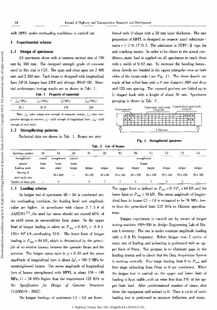
with a width of 0.02 mm. To increase the bonding forces,
shear dowels are bonded in the upper triangular area on both
sides of the beam ends (see Fig. 1) . The shear dowels are
made of hot-rolled bars with a 4 mm diameter,600 mm deep
and 120 mm spacing. The exposed portions are folded up to
L-shaped hook with a length of about 30 mm. Specimens
grouping is shown in Tab. 2.
Transverse steel mesh Lognitudinal steel mesh Shear pins d> 6 <f>6@100 '>' 6@50
• 4 V /- • • • • • • •
j 2 200 mm . V
Fig. 1 Strengthened specimen
Tab. 2 List of beams
Specimen number A0 Al Bl B2 B3 B4 Cl C2 C3 C4
Strengthened control strengthened control strengthened
pattern beam beam beam beams
Loading mode static static fatigue fatigue fatigue fatigue fatigue fatigue fatigue fatigue fatigue
Spacing of
steel mesh/mm - 50x100 - 30x60 30x60 50 x 100 50 x 100 50 x 100 50 x 100 50x100 50x100
Number of shear pins _ 5 - 5 7 7 5 7 5 3 -
1.3 Loading scheme As fatigue test of specimens B0 ~ B4 is conducted un-
der overloading condition, the loading level and amplitude
value are higher. In accordance with clause 5.7.3.4 of
AASHTO ,the steel bar stress should not exceed 60% of
its yield stress in serviceability limit states. So the upper
limit of fatigue loading is taken as Pmax = 0.8 Py = 0.8x
130= 104 kN, overloading 33% . The lower limit of fatigue
loading is fmin = 44 kN, which is determined by the princi-
ple of no relative bounce between the spreader beam and the
actuator. The fatigue stress ratio is p = 0.42 and the stress
amplitude of longitudinal bars is about A/y = 160.5 MPa for
unstrengthened beams. The stress amplitude of longitudinal
bars of beams strengthened with HPFL is about 136 ~ 149
MPa, 11-24 MPa higher than the requirement 125 MPa in
the Specification for Design of Concrete Structures
(GB50010-2002).
The fatigue loadings of specimens Cl ~ C4 are lower.
The upper limit is defined as Pmax = 0.5Py = 64 kN and the
lower limit as Pm;n = 30 kN. The stress amplitude of longitu-
dinal bars in beams Cl ~ C4 is estimated to be 76 MPa, low-
er than the prescribed limit 125 MPa in Chinese specifica-
tions .
Fatigue experiment is carried out by means of fatigue
testing machine PMS-500 in Bridge Engineering Lab of Hu-
nan University. The test is under constant amplitude loading
with a 0.8 Hz frequency. Before fatigue test, 2 cycles of
static test of loading and unloading is performed with an up-
per limit of Pmax. The purpose is to eliminate gaps in the
loading system and to check that the Data Acquisition System
is working correctly. Five-stage loading from 0 to Pmlix and
four stage unloading from Pmax to 0 are conducted. When
the fatigue test is carried on, the upper and lower limit of
loading is kept stable, with an error less than 5% of the up-
per limit load. After predetermined number of times, shut
down the equipment and unload to 0. Then a cycle of static
loading test is performed to measure deflection and strain.
J. Highway Transp. Res. Dev. (English Ed.) 2010.4:57-61.
Dow
nloa
ded
from
asc
elib
rary
.org
by
K K
Wag
h In
st O
f E
ngg
Edu
catio
n &
Res
earc
h, N
asik
on
02/1
2/15
. Cop
yrig
ht A
SCE
. For
per
sona
l use
onl
y; a
ll ri
ghts
res
erve
d.
SHANG Shouping.et al: Experimental Research on Fatigue Behavior of Reinforced Concrete ReamsStrengthened with HPFL- 59
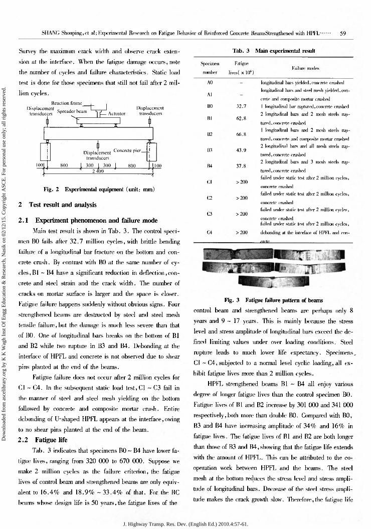
Survey the maximum crack width and observe crack exten-
sion at the interface. When the fatigue damage occurs, note
the number of cycles and failure characteristics. Static load
test is done for those specimens that still not fail after 2 mil-
lion cycles.
Tab. 3 Main experimental result
Reaction frame Displacement „ . ,
transducers Spreader beam
I VEZI IE Actuator
Displacement transducers
100 800
Displacement Concrete pier_ transducers
300 I 300 L 300 I 300 I "* 2400
soo 100
Fig. 2 Experimental equipment (unit: mm)
2 Test result and analysis
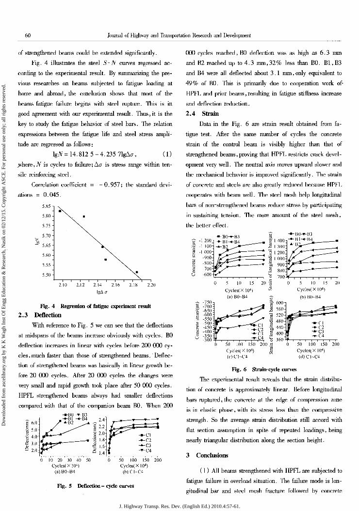
2.1 Experiment phenomenon and failure mode Main test result is shown in Tab. 3. The control speci-
men B0 fails after 32.7 million cycles, with brittle bending
failure of a longitudinal bar fracture on the bottom and con-
crete crush. By contrast with B0 at the same number of cy-
cles, Bl ~ B4 have a significant reduction in deflection, con-
crete and steel strain and the crack width. The number of
cracks on mortar surface is larger and the space is closer.
Fatigue failure happens suddenly without obvious signs. Four
strengthened beams are destructed by steel and steel mesh
tensile failure, but the damage is much less severe than that
of BO. One of longitudinal bars breaks on the bottom of Bl
and B2 while two rupture in B3 and B4. Debonding at the
interface of HPFL and concrete is not observed due to shear
pins planted at the end of the beams.
Fatigue failure does not occur after 2 million cycles for
Cl ~ C4. In the subsequent static load test,Cl - C3 fail in
the manner of steel and steel mesh yielding on the bottom
followed by concrete and composite mortar crush. Entire
debonding of U-shaped HPFL appears at the interface, owing
to no shear pins planted at the end of the beam.
2.2 Fatigue life Tab. 3 indicates that specimens B0 ~ B4 have lower fa-
tigue lives, ranging from 320 000 to 670 000. Suppose we
make 2 million cycles as the failure criterion, the fatigue
lives of control beam and strengthened beams are only equiv-
alent to 16.4% and 18.9% ~ 33.4% of that. For the RC
beams whose design life is 50 years, the fatigue lives of the
Specimen
number
Fatigue
lives( x 104) Failure modes
A0 -
Al -
B0 32.7
Bl 62.8
B2 66.8
B3 43.9
B4 37.8
Cl >200
a >200
a >200
a >200
longitudinal bars yielded, concrete crushed
longitudinal l>ars and steel mesh yielded, con-
crete and composite mortar crusruxl
1 longitudinal bar ruptured, concrete crushed
2 longitudinal l>ars and 2 mesh steels rup-
tured , concrete crushed
1 longitudinal bars and 2 mesh steels rup-
tured , concrete and composite mortar crushed
2 longitudinal l>ars and all mesh steels rup-
tured , concrete cruslu*l
2 longitudinal bars and 3 mesh steels rup-
tured, concrete crushed
failed under static test after 2 million cycles,
concrete crushed
failed under static test after 2 million cycles,
concrete crushed
failed under static test after 2 mi 11 inn cycles,
concrete crushed failed under static test after 2 million cycles,
dclxmding at the interface of HPFL and con-
Fig. 3 Fatigue failure pattern of beams
control beam and strengthened beams are perhaps only 8
years and 9-17 years. This is mainly because the stress
level and stress amplitude of longitudinal bars exceed the de-
fined limiting values under over loading conditions. Steel
rupture leads to much lower life expectancy. Specimens,
Cl ~ C4, subjected to a normal level cyclic loading, all ex-
hibit fatigue lives more than 2 million cycles.
HPFL strengthened beams Bl ~ B4 all enjoy various
degree of longer fatigue lives than the control specimen B0.
Fatigue lives of Bl and B2 increase by 301 000 and 341 000
respectively, both more than double B0. Compared with B0,
B3 and B4 have increasing amplitude of 34% and 16% in
fatigue lives. The fatigue lives of Bl and B2 are both longer
than those of B3 and B4, showing that the fatigue life extends
with the amount of HPFL. This can be attributed to the co-
operation work between HPFL and the beams. The steel
mesh at the bottom reduces the stress level and stress ampli-
tude of longitudinal bars. Decrease of the steel stress ampli-
tude makes the crack growth slow. Therefore, the fatigue life
J. Highway Transp. Res. Dev. (English Ed.) 2010.4:57-61.
Dow
nloa
ded
from
asc
elib
rary
.org
by
K K
Wag
h In
st O
f E
ngg
Edu
catio
n &
Res
earc
h, N
asik
on
02/1
2/15
. Cop
yrig
ht A
SCE
. For
per
sona
l use
onl
y; a
ll ri
ghts
res
erve
d.
60 Journal of Highway and Transportation Research and Development
of strengthened beams could be extended significantly.
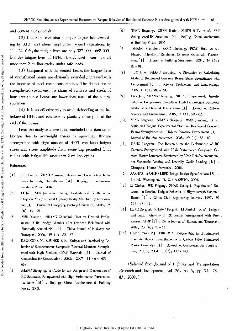
Fig. 4 illustrates the steel S~N curves regressed ac-
cording to the experimental result. By summarizing the pre-
vious researches on beams subjected to fatigue loading at
home and abroad, the conclusion shows that most of the
beams fatigue failure begins with steel rupture. This is in
good agreement with our experimental result. Thus, it is the
key to study the fatigue behavior of steel bars. The relation
expressions between the fatigue life and steel stress ampli-
tude are regressed as follows:
]gN= 14.812 5-4.235 71gAa, (1)
jvhere, N is cycles to failure; A<7 is stress range within ten-
sile reinforcing steel.
Correlation coefficient = -0.957; the standard devi-
ations = 0.045.
2.20
2.3 Fig. 4 Regression of fatigue experiment result
Deflection With reference to Fig. 5 we can see that the deflections
at midspans of the beams increase obviously with cycles. B0
deflection increases in linear with cycles before 200 000 cy-
cles , much faster than those of strengthened beams. Deflec-
tion of strengthened beams was basically in linear growth be-
fore 20 000 cycles. After 20 000 cycles the changes were
very small and rapid growth took place after 50 000 cycles.
HPFL strengthened beams always had smaller deflections
compared with that of the companion beam B0. When 200
-■-B0 -T-B3 .-•-Bl -4-B4
£ 6.0 /■^B2 ^ £ / ^^ £ 5.0 s^'^ - 4.0 :
& 3 0 <U u 2.0 lr
2.4 T--*—T—;—* | 2.2- ?2.0; yi^^ -*-c\ r, 1.8 J -»-C2 = 1 6 f -*-C3 Q 1.4: i ^c4
0 10 20 30 40 Cycles(X104)
(a) B0-B4
50 50 100 150 200 Cycles(X104) (b)Cl~C4
000 cycles reached, B0 deflection was as high as 6.3 mm
and B2 reached up to 4.3 mm, 32% less than B0. Bl, B3
and B4 were all deflected about 3.1 mm, only equivalent to
49% of B0. This is primarily due to cooperation work of-
HPFL and prior beams, resulting in fatigue stiffness increase
and deflection reduction.
2.4 Strain
Data in the Fig. 6 are strain result obtained from fa-
tigue test. After the same number of cycles the concrete
strain of the control beam is visibly higher than that of
strengthened beams, proving that HPFL restricts crack devel-
opment very well. The neutral axis moves upward slower and
the mechanical behavior is improved significantly. The strain
of concrete and steels are also greatly reduced because HPFL
cooperates with beam well. The steel mesh help longitudinal
bars of non-strengthened beams reduce stress by participating
in sustaining tension. The more amount of the steel mesh,
the better effect.
-1 200 -1 100 -1 000
-900 -800 -700:
-600
-■-B0-T-B3 I -»-Bl-«-B4
-.0^— -i*
5 10 15
Cycles* X104) (a) B0-B4
20 5 10 15 Cycles(XK)4)
(b) B0-B4
20
50 100 150 Cycles( X104) (c)Cl~C4
50 100 150 Cycles( X 104) (d)Cl~C4
200
Fig. 5 Deflection- cycle curves
Fig. 6 Strain-cycle curves
The experimental result reveals that the strain distribu-
tion of concrete is approximately linear. Before longitudinal
bars ruptured, the concrete at the edge of compression zone
is in elastic phase, with its stress less than the compressive
strength. So the average strain distribution still accord with
flat section assumption in spite of repeated loadings, being
nearly triangular distribution along the section height.
3 Conclusions
(1) All beams strengthened with HPFL are subjected to
fatigue failure in overload situation. The failure mode is lon-
gitudinal bar and steel mesh fracture followed by concrete
J. Highway Transp. Res. Dev. (English Ed.) 2010.4:57-61.
Dow
nloa
ded
from
asc
elib
rary
.org
by
K K
Wag
h In
st O
f E
ngg
Edu
catio
n &
Res
earc
h, N
asik
on
02/1
2/15
. Cop
yrig
ht A
SCE
. For
per
sona
l use
onl
y; a
ll ri
ghts
res
erve
d.
SHANG Shouping, et al; Experimental Research on Fatigue Behavior of Reinforced Concrete ReamsStrengthened with HPFL······ 61
and cement-mortar crush.
(2) Under the condition of upper fatigue load exceed
ing by 33 % and stress amplitudes beyond regulations by
11 - 24 MPa, the fatigue lives are only 327 000 - 668 000.
But the fatigue lives of HPFL strengthened beams are all
more than 2 million cycles under safe loads.
( 3) Compared with the control beam, the fatigue Ii ves
of strengthened beams are obviously extended, increased with
the increase of steel mesh consumption. The deflections of
strengthened specimens, the strain of concrete and steels of
four strengthened beams are lower than those of the control
specimen.
(4) It is an effective way to avoid debonding at the in
terface of HPFL and concrete by planting shear pins at the
end of the beams.
From the analysis above it is concluded that damage of
bridges due to overweight trucks is speeding. Bridges
strengthened with right amount of HPFL can keep fatigue
stress and stress amplitude from exceeding permitted limit
values, with fatigue life more than 2 million cycles.
References :
[1 J UU Laijun, ZHAO Xiaoxing. Design and Construction Tech
nique for Bridge Strengthening [MJ . Beijing: China Commu
nications Press, 2004.
[2J U Jian, SUN Jianyuan. Damage Evaluate and the Method of
Diagnose Study of Great Highway Bridge Structure by Overload
ing [JJ . Journal of Chongqing Jiaotong University, 2006, 25
(6); 19 - 2l.
[3 J SUN Xiaoyan, HUANG Chengkui. Test on Flexural Perfor
mance of RC Bridge Member after Overload Reinforced with
Externally Bonded FRP [J J . China Journal of Highway and
Transport, 2006, 19 (4): 82- 87.
[5J
DA WOOD SM. SUMNER R E. Fatigue and Overloading Be-
havior of Steel-concrete Composite Flexural Members Strength
ened with High Modulus CFRP Materials [J J . Journal of
Composites for Construction, ASCE, 2007, 11 (6): 659-
669.
SHANG Shouping. A Guide for the Design and Construction of
RC Structures Strengthened with High Performance Ferrocement
Laminate [M J . Beijing; China Architecture & Building
Press, 2008.
[6 J TENG Jinguang, CHEN Jianfei, SMfTII S T, et al. FRP
Strengthened RC Structures [MJ . Beijing: China Architecture
& Building Press, 2005.
[ 7 J SHANG Shouping, ZENG linghong, PENG Hui, et al.
Flexural Behavior of Reinforced Concrete Beams with Ferroce
ment [J J . Journal of Building Structures, 2003, 24 (6);
87 - 91.
[8J LUO libo, SHANG Shouping. A Discussion on Calculating
Model of Reinforced Concrete Beams Shear Strengthened with
Ferrocement [J J . Science Technology and Engineering,
2006,6 (6): 788-790.
[9J YAN Jun, SHANG Shouping, NlE Xu. Experimentallnvesti-
gation of Compressive Strength of High Performance Composite
Mortar after Elevated Temperature [J J . Journal of Railway
Science and Engineering, 2006 , 3 (4); 59 - 62.
[1OJ ZENG linghong, SHANG Shouping, WAN Jianping, et al.
Static and Fatigue Experimental Study on Reinforced Concrete
Beams Strengthened with High-performance Ferrocement [JJ
Journal of Building Structures, 2008, 29 (1): 83 - 89.
[11 J JIANG Longmin. The Research on the Performance of RC
Columns Strengthened with High Performance Composite Ce
ment Mortar Laminates Reinforced by Mesh Reinforcements un
der Monotonic Loading and Laterally Cyclic Loading [D J
Changsha: Hunan University, 2006.
[I2J AASHTO. AASHTO LRFD Bridge Design Specifications [SJ
3rd ed. Washington, D. C.: AASHTO, 2004.
[13J U Xiufen, WU Peigang, ZHAO Guangyi. Experimental Re
search on Bending Fatigue Behavior of High-strength Concrete
Beams [J J . China Civil Engineering Journal, 1997, 30
(5): 37 - 42.
[14J DENG Zongcai, ZHANG Pengfei, U Jianhui, et al. Fatigue
and Static Behaviors of RC Beams Strengthened with Pre- ~
stressed AFRP [JJ . China Journal of Highway and Transport,
2007, 20 (6): 49 - 55 .
[15J HEFFERNAN P J, ERKI M A. Fatigue Behavior of Reinforced
Concrete Beams Strengthened with Carbon Fiber Reinforced
Plastic Laminates [J J . Journal of Composites for Construc
tion, ASCE, 2004, 8 (2): 132-140.
(Selected from Journal of Highway and Transportation
Research and Development, vol. 26, no. 6, pp. 74 - 78 ,
83, 2009.)
J. Highway Transp. Res. Dev. (English Ed.) 2010.4:57-61.
Dow
nloa
ded
from
asc
elib
rary
.org
by
K K
Wag
h In
st O
f E
ngg
Edu
catio
n &
Res
earc
h, N
asik
on
02/1
2/15
. Cop
yrig
ht A
SCE
. For
per
sona
l use
onl
y; a
ll ri
ghts
res
erve
d.