Embed Size (px)
Citation preview

Joint Conference of 30th ISTS, 34th IEPC and 6th NSAT, Kobe-Hyogo, Japan
July 4 – 10, 2015
1
Experimental study of a high specific impulse plasma thruster PlaS-120
IEPC-2015-154 /ISTS-2015-b-154
Presented at Joint Conference of 30th International Symposium on Space Technology and Science 34th International Electric Propulsion Conference and 6th Nano-satellite Symposium,
Hyogo-Kobe, Japan July 4 – 10, 2015
M.Yu. Potapenko1, V.V. Gopanchuk2 FSUE EDB Fakel, Kaliningrad, 236001, Russia
D.V. Merkuriev3, P.G. Smirnov4 RIAME, Moscow, 125080, Russia
Abstract: This Paper presents the results of experimental investigations of the conceptual (engineering) model the PlaS-120 thruster with a hollow magnet anode. Results of initial research test, and also an analysis of its thrust performances in the power range from 2 to 6 kW with discharge voltage from 200 to 800 V and with discharge current from 6 to 20 A are given herein. This thruster model showed effective operation in high thrust modes up to 315 mN and in high specific impulse modes up to 3000 s given the total thrust efficiency is of not less than 50 %.
Nomenclature Id = discharge current; Ud = discharge voltage; Ga = anode gas flow rate; Ii = ion current; Ie = electron current; U = "cathode-ground" voltage; Ki = gas ionization rate; Pv/c = vacuum chamber dynamic pressure; F = thrust; Isp = specific impulse.
I. Introduction
tationary Plasma Thrusters (SPT) continue to find more and more applications in fulfillment of various maneuvers performed by spacecraft (S/C). One of the most wanted tasks of current concern is orbit raising
or orbit transfer fulfilled by SPTs. Heavy satellites of more than 3.0 tons in mass designed for operation in GEO require a multi-mode SPT of high efficiency which is able to fulfill both orbital transfer and station keeping. Therefore, the development of advanced and challenging S/C requires to design new and more effective SPTs with improved performances, higher operational dependability, better feasibility for integration and good compatibility with S/C.
1 Design Engineer, Ph.D., design department 2 Leading Designer, design department 3 Engineer, Ph.D. Student, test department 4 Engineer, Ph.D. Student, test department
S
Joint Conference of 30th ISTS, 34th IEPC and 6th NSAT, Kobe-Hyogo, Japan
July 4 – 10, 2015
2
II. High power plasma thruster PlaS-120CM EDB Fakel is being actively involved in development of plasma thrusters of the PlaS parametric family [1],
in particular the one with middle diameter of its accelerating channel (ACh) of ∅120 mm and with nominal discharge power of 5 kW which is named PlaS-120 (fig.1).
Figure 1. Plasma thruster PlaS-120 ser.01 during operation at RIAME's vacuum facility
Constructive scheme of the PlaS-120CM thruster is similar to the PlaS-40 design [2]. Distinctive feature of the PlaS-120CM is its cathode placement along thruster axis, which igniter is mounted on the internal magnet pole.
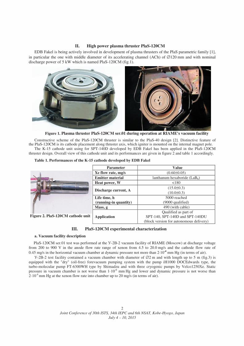
The K-15 cathode unit using for SPT-140D developed by EDB Fakel has been applied in the PlaS-120CM thruster design. Overall view of this cathode unit and its performances are given in figure 2 and table 1 accordingly.
Table 1. Performances of the K-15 cathode developed by EDB Fakel
Figure 2. PlaS-120CM cathode unit
Parameter Value Xe flow rate, mg/s (0.60±0.05) Emitter material lanthanum hexaboride (LaB6) Heat power, W <180
Discharge current, (15.0±0.3) (10.0±0.3)
Life time, h (running-in quantity)
5000 reached (9000 qualified)
Mass, g 490 (with cable)
Application Qualified as part of
SPT-140, SPT-140D and SPT-140DU (block version for autonomous delivery)
III. PlaS-120CM experimental characterization
. Vacuum facility description
PlaS-120CM ser.01 test was performed at the -2 -2 vacuum facility of RIAME (Moscow) at discharge voltage from 200 to 900 V in the anode flow rate range of xenon from 4.5 to 20.0 mg/s and the cathode flow rate of 0.45 mg/s in the horizontal vacuum chamber at dynamic pressure not more than 2⋅10-4 mm Hg (in terms of air).
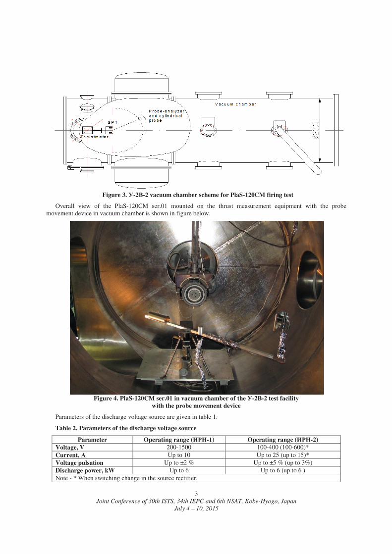
-2 -2 test facility contained a vacuum chamber with diameter of ∅2 m and with length up to 5 m (fig.3) is equipped with the "dry" (oil-free) forevacuum pumping system with the pump iH1000 DOCEdwards type, the turbo-molecular pump FT-6300WH type by Shimadzu and with three cryogenic pumps by Velco1250 . Static pressure in vacuum chamber is not worse than 1·10-6 mm Hg and lower and dynamic pressure is not worse than 2·10-4 mm Hg at the xenon flow rate into chamber up to 20 mg/s (in terms of air).
Joint Conference of 30th ISTS, 34th IEPC and 6th NSAT, Kobe-Hyogo, Japan
July 4 – 10, 2015
3
Figure 3. -2 -2 vacuum chamber scheme for PlaS-120CM firing test
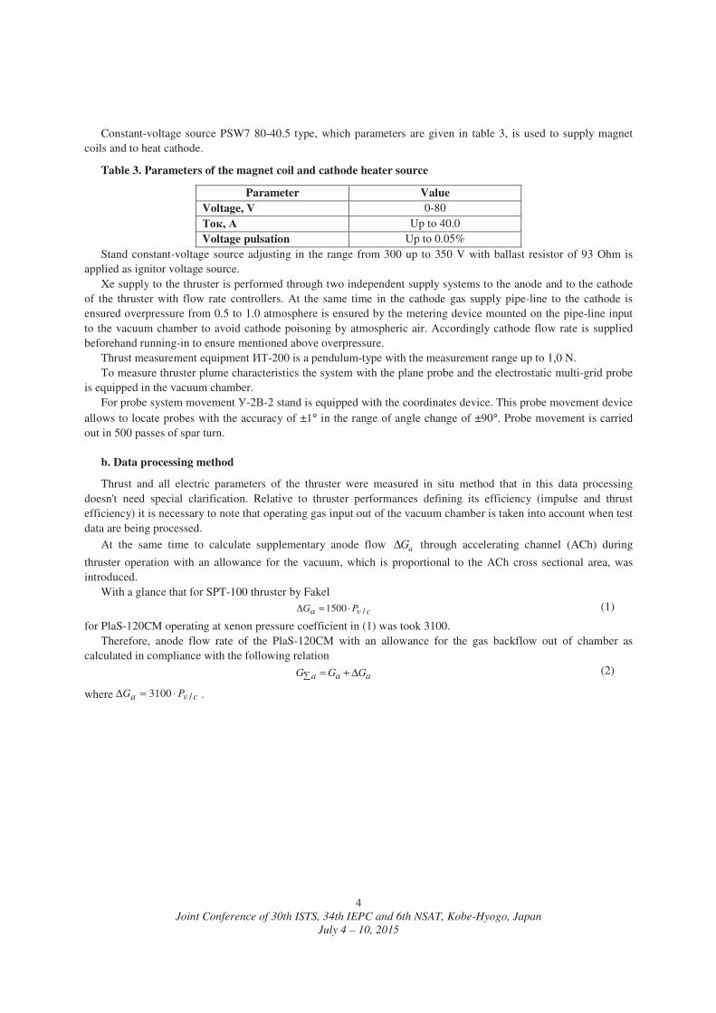
Overall view of the PlaS-120CM ser.01 mounted on the thrust measurement equipment with the probe movement device in vacuum chamber is shown in figure below.
Figure 4. PlaS-120CM ser.01 in vacuum chamber of the -2 -2 test facility
with the probe movement device
Parameters of the discharge voltage source are given in table 1.
Table 2. Parameters of the discharge voltage source
Parameter Operating range ( -1) Operating range ( -2) Voltage, V 200-1500 100-400 (100-600)* Current, Up to 10 Up to 25 (up to 15)* Voltage pulsation Up to ±2 % Up to ±5 % (up to 3%) Discharge power, kW Up to 6 Up to 6 (up to 6 ) Note - * When switching change in the source rectifier.
Joint Conference of 30th ISTS, 34th IEPC and 6th NSAT, Kobe-Hyogo, Japan
July 4 – 10, 2015
4
Constant-voltage source PSW7 80-40.5 type, which parameters are given in table 3, is used to supply magnet coils and to heat cathode.
Table 3. Parameters of the magnet coil and cathode heater source
Parameter Value Voltage, V 0-80
, Up to 40.0 Voltage pulsation Up to 0.05%
Stand constant-voltage source adjusting in the range from 300 up to 350 V with ballast resistor of 93 Ohm is applied as ignitor voltage source.
Xe supply to the thruster is performed through two independent supply systems to the anode and to the cathode of the thruster with flow rate controllers. At the same time in the cathode gas supply pipe-line to the cathode is ensured overpressure from 0.5 to 1.0 atmosphere is ensured by the metering device mounted on the pipe-line input to the vacuum chamber to avoid cathode poisoning by atmospheric air. Accordingly cathode flow rate is supplied beforehand running-in to ensure mentioned above overpressure.
Thrust measurement equipment -200 is a pendulum-type with the measurement range up to 1,0 N. To measure thruster plume characteristics the system with the plane probe and the electrostatic multi-grid probe
is equipped in the vacuum chamber. For probe system movement -2 -2 stand is equipped with the coordinates device. This probe movement device
allows to locate probes with the accuracy of ±1° in the range of angle change of ±90°. Probe movement is carried out in 500 passes of spar turn.
b. Data processing method
Thrust and all electric parameters of the thruster were measured in situ method that in this data processing doesn't need special clarification. Relative to thruster performances defining its efficiency (impulse and thrust efficiency) it is necessary to note that operating gas input out of the vacuum chamber is taken into account when test data are being processed.
At the same time to calculate supplementary anode flow aGΔ through accelerating channel (ACh) during
thruster operation with an allowance for the vacuum, which is proportional to the ACh cross sectional area, was introduced.
With a glance that for SPT-100 thruster by Fakel
cva PG /1500 ⋅≈Δ (1)
for PlaS-120CM operating at xenon pressure coefficient in (1) was took 3100. Therefore, anode flow rate of the PlaS-120CM with an allowance for the gas backflow out of chamber as
calculated in compliance with the following relation
aaa GGG Δ+= (2)
where cva PG /3100 ⋅=Δ .
Joint Conference of 30th ISTS, 34th IEPC and 6th NSAT, Kobe-Hyogo, Japan
July 4 – 10, 2015
5
. Parametric test results
Results of the PlaS-120CM ser.01 parametric test including C-V characteristics determination at different flow rate level, are given in figures 7-10.
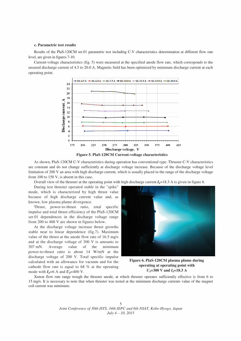
Current-voltage characteristics (fig. 5) were measured at the specified anode flow rate, which corresponds to the ensured discharge current of 4.5 to 20.0 . Magnetic field has been optimized by minimum discharge current at each operating point.
Figure 5. PlaS-120CM Current-voltage characteristics
As shown, PlaS-120CM C-V characteristics during operation has conventional type. Thruster C-V characteristics are constant and do not change sufficiently at discharge voltage increase. Because of the discharge voltage level limitation of 200 V an area with high discharge current, which is usually placed in the range of the discharge voltage from 100 to 150 V, is absent in this case.
Overall view of the thruster at the operating point with high discharge current Id=18.3 A is given in figure 6. During test thruster operated stable in the "spike"
mode, which is characterized by high thrust value because of high discharge current value and, as known, low plasma plume divergence.
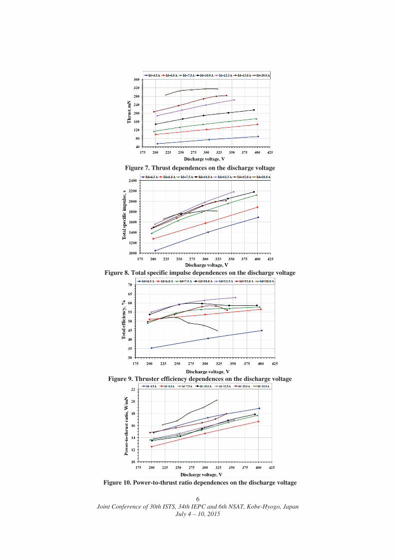
Thrust, power-to-thrust ratio, total specific impulse and total thrust efficiency of the PlaS-120CM ser.01 dependences in the discharge voltage range from 200 to 400 V are shown in figures below.
At the discharge voltage increase thrust growths stable near to linear dependence (fig.7). Maximum value of the thrust at the anode flow rate of 16.5 mg/s and at the discharge voltage of 300 V is amounts to 307 mN. Average value of the minimum power-to-thrust ratio is about 14 W/mN at the discharge voltage of 200 V. Total specific impulse calculated with an allowance for vacuum and for the cathode flow rate is equal to 68 % at the operating mode with Id=6 and Ud=400 V.
Figure 6. PlaS-120CM plasma plume during operating at operating point with
Ud=300 V and Id=18.3
Xenon flow rate range trough the thruster anode, at which thruster operates sufficiently effective is from 6 to 15 mg/s. It is necessary to note that when thruster was tested at the minimum discharge currents value of the magnet coil current was minimum.
Joint Conference of 30th ISTS, 34th IEPC and 6th NSAT, Kobe-Hyogo, Japan
July 4 – 10, 2015
6
Figure 7. Thrust dependences on the discharge voltage
Figure 8. Total specific impulse dependences on the discharge voltage
Figure 9. Thruster efficiency dependences on the discharge voltage
Figure 10. Power-to-thrust ratio dependences on the discharge voltage
Joint Conference of 30th ISTS, 34th IEPC and 6th NSAT, Kobe-Hyogo, Japan
July 4 – 10, 2015
7
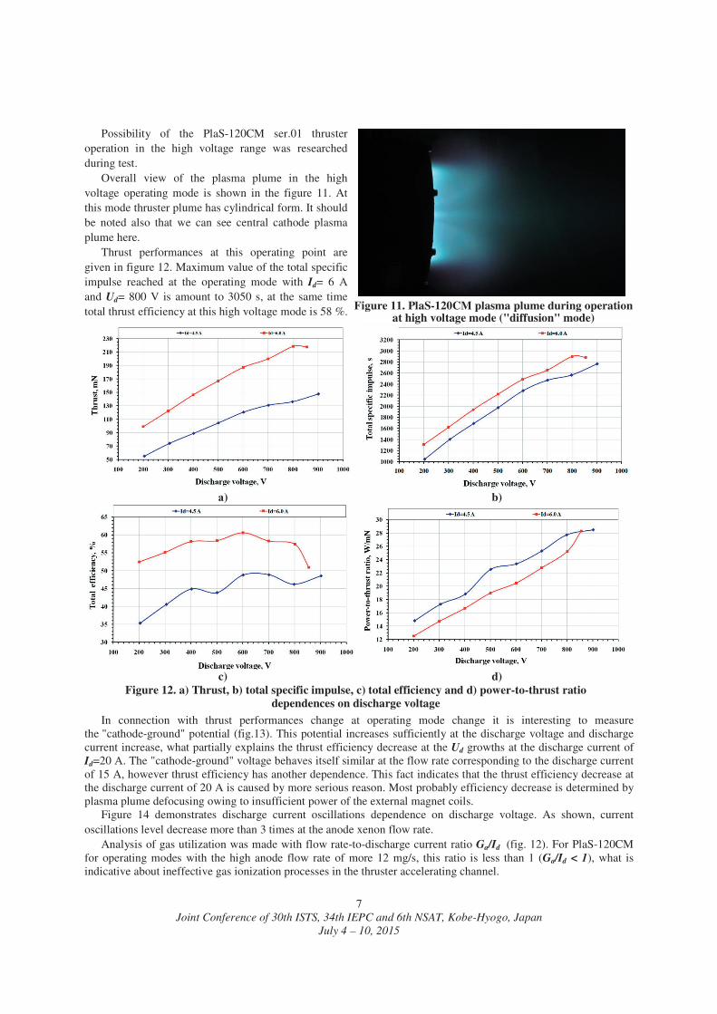
Possibility of the PlaS-120CM ser.01 thruster operation in the high voltage range was researched during test.
Overall view of the plasma plume in the high voltage operating mode is shown in the figure 11. At this mode thruster plume has cylindrical form. It should be noted also that we can see central cathode plasma plume here.
Thrust performances at this operating point are given in figure 12. Maximum value of the total specific impulse reached at the operating mode with Id= 6 and Ud= 800 V is amount to 3050 s, at the same time total thrust efficiency at this high voltage mode is 58 %.
Figure 11. PlaS-120CM plasma plume during operation
at high voltage mode ("diffusion" mode)
) b)
c) d)
Figure 12. a) Thrust, b) total specific impulse, c) total efficiency and d) power-to-thrust ratio dependences on discharge voltage
In connection with thrust performances change at operating mode change it is interesting to measure the "cathode-ground" potential (fig.13). This potential increases sufficiently at the discharge voltage and discharge current increase, what partially explains the thrust efficiency decrease at the Ud growths at the discharge current of Id=20 . The "cathode-ground" voltage behaves itself similar at the flow rate corresponding to the discharge current of 15 A, however thrust efficiency has another dependence. This fact indicates that the thrust efficiency decrease at the discharge current of 20 A is caused by more serious reason. Most probably efficiency decrease is determined by plasma plume defocusing owing to insufficient power of the external magnet coils.
Figure 14 demonstrates discharge current oscillations dependence on discharge voltage. As shown, current oscillations level decrease more than 3 times at the anode xenon flow rate.
Analysis of gas utilization was made with flow rate-to-discharge current ratio Ga/Id (fig. 12). For PlaS-120CM for operating modes with the high anode flow rate of more 12 mg/s, this ratio is less than 1 (Ga/Id < 1), what is indicative about ineffective gas ionization processes in the thruster accelerating channel.

Joint Conference of 30th ISTS, 34th IEPC and 6th NSAT, Kobe-Hyogo, Japan
July 4 – 10, 2015
8
Figure 13. "Cathode ground" voltage dependences on the discharge voltage
Figure 14. RMS discharge current amplitude dependencies on discharge voltage
Figure 15. Ga/Id ratio dependences on discharge voltage
Representative performances of the PlaS-120 CM ser.01 at different operating mode are given in the cumulative table 4.
Table 2. PlaS-120 ser. 01 representative performances
Operating mode Ga, mg/s Ud, V Id, N, W F, mN Isp, s Eff, %
Minimum power level 7.1 200 6.2 1240 100 1400 52 Maximum F 16.5 322 19.8 6376 315 1860 46 Maximum Isp 7.1 800 6.9 5520 220 3020 58
Power level N=2.5 kW Maximum F 9.4 253 9.7 2455 168 1700 59 Maximum Isp 7.1 400 6.1 2440 145 2030 58
Power level N=3.8 kW Maximum F 11.6 299 12.6 3764 226 1877 61 Maximum Isp 7.1 600 6.4 3840 187 2670 61
Power level N=4.5 kW Maximum F 16.5 220 21.0 4613 274 1615 51 Maximum Isp 7.1 700 6.5 4550 200 2780 58
Power level N=6.0 kW Maximum F 16.5 229 20.2 5999 307 1810 48 Maximum Isp 7.1 855 7.2 6156 216 2990 52
Test results of the PlaS-120CM ser.01 demonstrated that this constructive scheme is more effective at the operating modes with high discharge power. Similar to the thruster with a hollow magnet anode of smaller dimension type PlaS-40 [3], the PlaS-120CM thruster is able to effective operate at the modes, which are typical for the thrusters of bigger dimension type and higher discharge power without mass-size and energy characteristics expansion.

Joint Conference of 30th ISTS, 34th IEPC and 6th NSAT, Kobe-Hyogo, Japan
July 4 – 10, 2015
9
IV. Conclusion Along with SPT of the conventional type, as, for example, SPT-140 or SPT-140D, EDB Fakel performs research
works with the new high specific impulse thruster PlaS-120CM with the nominal discharge power of 6 kW. PlaS-120CM test at RIAME facilities (Moscow) confirmed possibility of thruster operation in the wide range of
the discharge voltage and the discharge current given performances level is comparable to SPT-140 bigger dimensions type thrusters performances.
By the PlaS-120CM research results it is determined that the new scheme thruster is able to ensure effective operation both at the high thrust mode and also at the high specific impulse mode given the total thrust efficiency is not less than 50 %.
The following performances are reached at the PlaS-120CM for the first time - minimal power-to-thrust ratio of 12.5 W/mN, thrust efficiency of 52 % at the discharge voltage of 200 V an
discharge power of 1240 W; - maximum thrust efficiency of 61 %, total specific impulse of 2680 s with an allowance for the cathode flow
rate at the discharge voltage of 600 V and the discharge power of 3840 W. Further improvements of the PlaS-120CM thruster constructive scheme are going on. Further modernization of
thruster magnet system is aimed to improve thruster operation efficiency in the range of discharge voltage up to 1000 V and more.
References
1 M.Yu. Potapenko, V.V. Gopanchuk. Characteristic Relationship between Dimensions and Parameters of a hybrid Plasma Thruster // IEPC-2011-042, 32nd International Electric Propulsion Conference, Wiesbaden, Germany, September 11 – 15, 2011.
2 M.Yu. Potapenko, V.V. Gopanchuk. Development and Research of the Plasma Thruster with a hollow magnet Anode PlaS-40 // IEPC-2013, 33rd International Electric Propulsion Conference, The George Washington University, Washington, D.C., USA, October 6 – 10, 2013.
3 M.Yu. Potapenko, V.V. Gopanchuk. Experimental study of performances of the plasma thruster with a hollow magnet anode // SP2014_2965047, Space Propulsion Conference, Cologne, Germany, May 19 – 22, 2014.