Embed Size (px)
DESCRIPTION
Eccentrically Loaded Columns Strengthened Using a Steel Jacketing Technique
Citation preview
Abstract—An experimental study of Reinforced Concrete, RC,
columns strengthened using a steel jacketing technique was
conducted. The jacketing technique consisted of four steel vertical
angles installed at the corners of the column joined by horizontal
steel straps confining the column externally. The effectiveness of the
technique was evaluated by testing the RC column specimens under
eccentric monotonic loading until failure occurred. Strain gauges
were installed to monitor the strains in the internal reinforcement as
well as the external jacketing system. The effectiveness of the
jacketing technique was demonstrated, and the parameters affecting
the technique were studied.
Keywords—Reinforced Concrete Columns, Steel Jacketing,
Strengthening, Eccentric Load.
I. INTRODUCTION
OLUMNS are basically vertical compression members
that transfer axial loads to the foundations. Although the
main function of the column is to transfer axial loads, most of
the time, columns are subjected to moments as well. This may
be due to accidental eccentricity arising from minor
misalignment during construction, or due to reduction of the
column size in multistory buildings. This may also occur due
to lateral drift, even in cases when the columns are not part of
the structural system resisting horizontal forces.
Many researchers investigated the strengthening of columns
subjected to eccentric loads. The basic idea in most of the
research conducted was to increase the concrete confinement
in order to achieve increased strength. This was done most of
the time by wrapping the concrete column using Fiber
Reinforced Polymer, FRP, carbon or glass sheets. Li et al. [1],
Parvin et al. [2], Bahaa et al. [3], Yuan et al. [4] and Benzaid
[5] are some examples of recent studies conducted using FRP
as a wrapping material for strengthening columns subjected to
eccentric loading. Some researchers used steel as a
confinement material by completely wrapping the column
with steel sheets, e.g. Ramirez et al. [6] and Sakino et al. [7].
Others used partial confining by using steel cages [8]-[11].
Some researchers used only steel collars for the confinement
e.g. Chapman et al. [12]. It is observed that more research is
needed to determine the factors that affect the efficiency of the
material used versus the requirements in both strength and
ductility.
In this paper an experimental program for testing square
Reinforced Concrete, RC, columns subjected to eccentric
M. K. Elsamny, A. A. Hussein, and M. K. Abd-Elhamed are with the Civil
Engineering Department, Azhar University, Cairo, Egypt. A. M. Nafie is with the Civil Engineering Department, Azhar University,
Cairo, Egypt (e-mail: [email protected]).
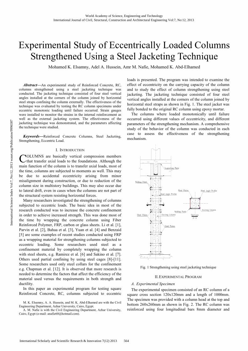
loads is presented. The program was intended to examine the
effect of eccentricity on the carrying capacity of the column
and to study the effect of column strengthening using steel
jacketing. The jacketing technique consisted of four steel
vertical angles installed at the corners of the column joined by
horizontal steel straps as shown in Fig. 1. The steel jacket was
fully bonded to the original RC column using epoxy mortar.
The columns where loaded monotonically until failure
occurred using different values of eccentricity, and different
parameters of the strengthening mechanism. A comprehensive
study of the behavior of the column was conducted in each
case to assess the effectiveness of the strengthening
mechanism.
Fig. 1 Strengthening using steel jacketing technique
II. EXPERIMENTAL PROGRAM
A. Experimental Specimen
The experimental specimen consisted of an RC column of a
square cross section 120x120mm and a length of 1000mm.
The specimen was provided with a column head at the top and
bottom 260x260mm as shown in Fig. 2. The RC column was
reinforced using four longitudinal bars 8mm diameter and
Mohamed K. Elsamny, Adel A. Hussein, Amr M. Nafie, Mohamed K. Abd-Elhamed
Experimental Study of Eccentrically Loaded Columns
Strengthened Using a Steel Jacketing Technique
C
World Academy of Science, Engineering and TechnologyInternational Journal of Civil, Structural, Construction and Architectural Engineering Vol:7, No:12, 2013
564International Scholarly and Scientific Research & Innovation 7(12) 2013
Inte
rnat
iona
l Sci
ence
Ind
ex V
ol:7
, No:
12, 2
013
was
et.o
rg/P
ublic
atio
n/99
9658
7
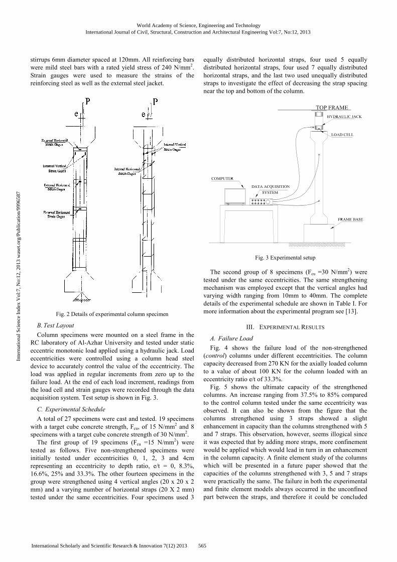
stirrups 6mm diameter spaced at 120mm. All reinforcing bars
were mild steel bars with a rated yield stress of 240 N/mm2.
Strain gauges were used to measure the strains of the
reinforcing steel as well as the external steel jacket.
Fig. 2 Details of experimental column specimen
B. Test Layout
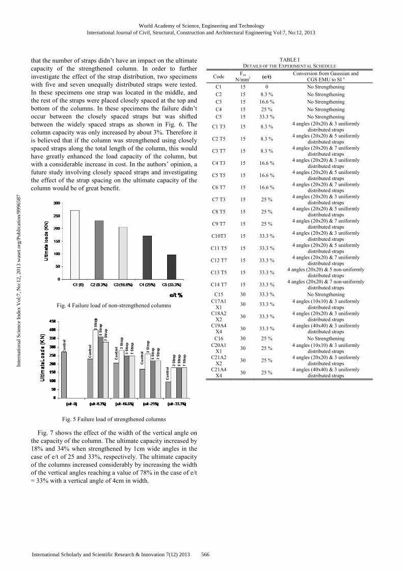
Column specimens were mounted on a steel frame in the
RC laboratory of Al-Azhar University and tested under static
eccentric monotonic load applied using a hydraulic jack. Load
eccentricities were controlled using a column head steel
device to accurately control the value of the eccentricity. The
load was applied in regular increments from zero up to the
failure load. At the end of each load increment, readings from
the load cell and strain gauges were recorded through the data
acquisition system. Test setup is shown in Fig. 3.
C. Experimental Schedule
A total of 27 specimens were cast and tested. 19 specimens
with a target cube concrete strength, Fcu, of 15 N/mm2 and 8
specimens with a target cube concrete strength of 30 N/mm2.
The first group of 19 specimens (Fcu =15 N/mm2) were
tested as follows. Five non-strengthened specimens were
initially tested under eccentricities 0, 1, 2, 3 and 4cm
representing an eccentricity to depth ratio, e/t = 0, 8.3%,
16.6%, 25% and 33.3%. The other fourteen specimens in the
group were strengthened using 4 vertical angles (20 x 20 x 2
mm) and a varying number of horizontal straps (20 X 2 mm)
tested under the same eccentricities. Four specimens used 3
equally distributed horizontal straps, four used 5 equally
distributed horizontal straps, four used 7 equally distributed
horizontal straps, and the last two used unequally distributed
straps to investigate the effect of decreasing the strap spacing
near the top and bottom of the column.
Fig. 3 Experimental setup
The second group of 8 specimens (Fcu =30 N/mm2) were
tested under the same eccentricities. The same strengthening
mechanism was employed except that the vertical angles had
varying width ranging from 10mm to 40mm. The complete
details of the experimental schedule are shown in Table I. For
more information about the experimental program see [13].
III. EXPERIMENTAL RESULTS
A. Failure Load
Fig. 4 shows the failure load of the non-strengthened
(control) columns under different eccentricities. The column
capacity decreased from 270 KN for the axially loaded column
to a value of about 100 KN for the column loaded with an
eccentricity ratio e/t of 33.3%.
Fig. 5 shows the ultimate capacity of the strengthened
columns. An increase ranging from 37.5% to 85% compared
to the control column tested under the same eccentricity was
observed. It can also be shown from the figure that the
columns strengthened using 3 straps showed a slight
enhancement in capacity than the columns strengthened with 5
and 7 straps. This observation, however, seems illogical since
it was expected that by adding more straps, more confinement
would be applied which would lead in turn in an enhancement
in the column capacity. A finite element study of the columns
which will be presented in a future paper showed that the
capacities of the columns strengthened with 3, 5 and 7 straps
were practically the same. The failure in both the experimental
and finite element models always occurred in the unconfined
part between the straps, and therefore it could be concluded
World Academy of Science, Engineering and TechnologyInternational Journal of Civil, Structural, Construction and Architectural Engineering Vol:7, No:12, 2013
565International Scholarly and Scientific Research & Innovation 7(12) 2013
Inte
rnat
iona
l Sci
ence
Ind
ex V
ol:7
, No:
12, 2
013
was
et.o
rg/P
ublic
atio
n/99
9658
7
that the number of straps didn’t have an impact on the ultimate
capacity of the strengthened column. In order to further
investigate the effect of the strap distribution, two specimens
with five and seven unequally distributed straps were tested.
In these specimens one strap was located in the middle, and
the rest of the straps were placed closely spaced at the top and
bottom of the columns. In these specimens the failure didn’t
occur between the closely spaced straps but was shifted
between the widely spaced straps as shown in Fig. 6. The
column capacity was only increased by about 3%. Therefore it
is believed that if the column was strengthened using closely
spaced straps along the total length of the column, this would
have greatly enhanced the load capacity of the column, but
with a considerable increase in cost. In the authors’ opinion, a
future study involving closely spaced straps and investigating
the effect of the strap spacing on the ultimate capacity of the
column would be of great benefit.
Fig. 4 Failure load of non-strengthened columns
Fig. 5 Failure load of strengthened columns
Fig. 7 shows the effect of the width of the vertical angle on
the capacity of the column. The ultimate capacity increased by
18% and 34% when strengthened by 1cm wide angles in the
case of e/t of 25 and 33%, respectively. The ultimate capacity
of the columns increased considerably by increasing the width
of the vertical angles reaching a value of 78% in the case of e/t
= 33% with a vertical angle of 4cm in width.
TABLE I
DETAILS OF THE EXPERIMENTAL SCHEDULE
Code Fcu
N/mm2 (e/t)
Conversion from Gaussian and
CGS EMU to SI a
C1 15 0 No Strengthening
C2 15 8.3 % No Strengthening C3 15 16.6 % No Strengthening
C4 15 25 % No Strengthening C5 15 33.3 % No Strengthening
C1 T3 15 8.3 % 4 angles (20x20) & 3 uniformly
distributed straps
C2 T5 15 8.3 % 4 angles (20x20) & 5 uniformly
distributed straps
C3 T7 15 8.3 % 4 angles (20x20) & 7 uniformly
distributed straps
C4 T3 15 16.6 % 4 angles (20x20) & 3 uniformly
distributed straps
C5 T5 15 16.6 % 4 angles (20x20) & 5 uniformly
distributed straps
C6 T7 15 16.6 % 4 angles (20x20) & 7 uniformly
distributed straps
C7 T3 15 25 % 4 angles (20x20) & 3 uniformly
distributed straps
C8 T5 15 25 % 4 angles (20x20) & 5 uniformly
distributed straps
C9 T7 15 25 % 4 angles (20x20) & 7 uniformly
distributed straps
C10T3 15 33.3 % 4 angles (20x20) & 3 uniformly
distributed straps
C11 T5 15 33.3 % 4 angles (20x20) & 5 uniformly
distributed straps
C12 T7 15 33.3 % 4 angles (20x20) & 7 uniformly
distributed straps
C13 T5 15 33.3 % 4 angles (20x20) & 5 non-uniformly
distributed straps
C14 T7 15 33.3 % 4 angles (20x20) & 7 non-uniformly
distributed straps C15 30 33.3 % No Strengthening
C17A1
X1 30 33.3 %
4 angles (10x10) & 3 uniformly
distributed straps C18A2
X2 30 33.3 %
4 angles (20x20) & 3 uniformly
distributed straps
C19A4X4
30 33.3 % 4 angles (40x40) & 3 uniformly
distributed straps
C16 30 25 % No Strengthening
C20A1X1
30 25 % 4 angles (10x10) & 3 uniformly
distributed straps
C21A2
X2 30 25 %
4 angles (20x20) & 3 uniformly
distributed straps C21A4
X4 30 25 %
4 angles (40x40) & 3 uniformly
distributed straps
World Academy of Science, Engineering and TechnologyInternational Journal of Civil, Structural, Construction and Architectural Engineering Vol:7, No:12, 2013
566International Scholarly and Scientific Research & Innovation 7(12) 2013
Inte
rnat
iona
l Sci
ence
Ind
ex V
ol:7
, No:
12, 2
013
was
et.o
rg/P
ublic
atio
n/99
9658
7
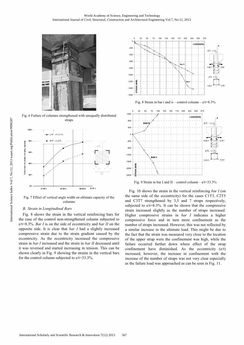
Fig. 6 Failure of columns strengthened with unequally distributed
straps
Fig. 7 Effect of vertical angle width on ultimate capacity of the
columns
B. Strain in Longitudinal Bars
Fig. 8 shows the strain in the vertical reinforcing bars for
the case of the control non-strengthened column subjected to
e/t=8.3%. Bar I is on the side of eccentricity and bar II on the
opposite side. It is clear that bar I had a slightly increased
compressive strain due to the strain gradient caused by the
eccentricity. As the eccentricity increased the compressive
strain in bar I increased and the strain in bar II decreased until
it was reversed and started increasing in tension. This can be
shown clearly in Fig. 9 showing the strains in the vertical bars
for the control column subjected to e/t=33.3%.
-1600
-1400
-1200
-1000
-800
-600
-400
-200
0
0 25 50 75 100 125 150 175 200 225 250 275
LOADS(KN)
STRAIN (M/M)
Bar I
Bar II
Fig. 8 Strain in bar i and ii – control column – e/t=8.3%
-2400
-2000
-1600
-1200
-800
-400
0
400
800
1200
0 25 50 75 100 125 150 175 200 225 250 275
LOADS(KN)
STRAIN (M/M)
BAR IIII
BAR IIIIIIII
Fig. 9 Strain in bar I and II – control column – e/t=33.3%
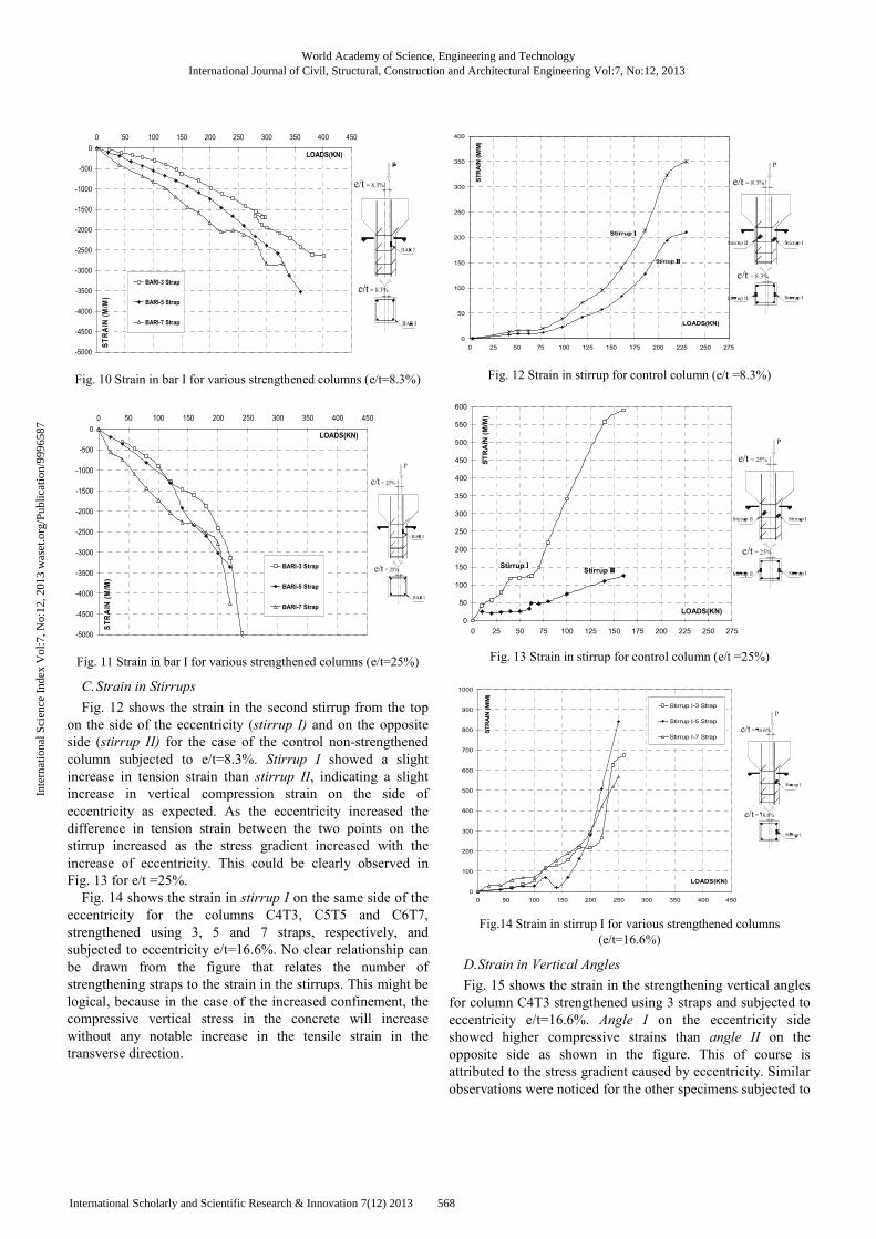
Fig. 10 shows the strain in the vertical reinforcing bar I (on
the same side of the eccentricity) for the cases C1T3, C2T5
and C3T7 strengthened by 3,5 and 7 straps respectively,
subjected to e/t=8.3%. It can be shown that the compressive
strain increased slightly as the number of straps increased.
Higher compressive strains in bar I indicates a higher
compressive force and in turn more confinement as the
number of straps increased. However, this was not reflected by
a similar increase in the ultimate load. This might be due to
the fact that the strain was measured very close to the location
of the upper strap were the confinement was high, while the
failure occurred further down where effect of the strap
confinement have diminished. As the eccentricity (e/t)
increased, however, the increase in confinement with the
increase of the number of straps was not very clear especially
as the failure load was approached as can be seen in Fig. 11.
World Academy of Science, Engineering and TechnologyInternational Journal of Civil, Structural, Construction and Architectural Engineering Vol:7, No:12, 2013
567International Scholarly and Scientific Research & Innovation 7(12) 2013
Inte
rnat
iona
l Sci
ence
Ind
ex V
ol:7
, No:
12, 2
013
was
et.o
rg/P
ublic
atio
n/99
9658
7
-5000
-4500
-4000
-3500
-3000
-2500
-2000
-1500
-1000
-500
0
0 50 100 150 200 250 300 350 400 450
LOADS(KN)
STRAIN (M/M)
BARI-3 Strap
BARI-5 Strap
BARI-7 Strap
Fig. 10 Strain in bar I for various strengthened columns (e/t=8.3%)
-5000
-4500
-4000
-3500
-3000
-2500
-2000
-1500
-1000
-500
0
0 50 100 150 200 250 300 350 400 450
LOADS(KN)
STRAIN (M/M)
BARI-3 Strap
BARI-5 Strap
BARI-7 Strap
Fig. 11 Strain in bar I for various strengthened columns (e/t=25%)
C. Strain in Stirrups
Fig. 12 shows the strain in the second stirrup from the top
on the side of the eccentricity (stirrup I) and on the opposite
side (stirrup II) for the case of the control non-strengthened
column subjected to e/t=8.3%. Stirrup I showed a slight
increase in tension strain than stirrup II, indicating a slight
increase in vertical compression strain on the side of
eccentricity as expected. As the eccentricity increased the
difference in tension strain between the two points on the
stirrup increased as the stress gradient increased with the
increase of eccentricity. This could be clearly observed in
Fig. 13 for e/t =25%.
Fig. 14 shows the strain in stirrup I on the same side of the
eccentricity for the columns C4T3, C5T5 and C6T7,
strengthened using 3, 5 and 7 straps, respectively, and
subjected to eccentricity e/t=16.6%. No clear relationship can
be drawn from the figure that relates the number of
strengthening straps to the strain in the stirrups. This might be
logical, because in the case of the increased confinement, the
compressive vertical stress in the concrete will increase
without any notable increase in the tensile strain in the
transverse direction.
0
50
100
150
200
250
300
350
400
0 25 50 75 100 125 150 175 200 225 250 275
LOADS(KN)
STRAIN (M/M)
Stirrup IIII
Stirrup IIIIIIII
Fig. 12 Strain in stirrup for control column (e/t =8.3%)
0
50
100
150
200
250
300
350
400
450
500
550
600
0 25 50 75 100 125 150 175 200 225 250 275
LOADS(KN)
STRAIN (M/M)
Stirrup IIIIStirrup IIIIIIII
Fig. 13 Strain in stirrup for control column (e/t =25%)
0
100
200
300
400
500
600
700
800
900
1000
0 50 100 150 200 250 300 350 400 450
LOADS(KN)
STRAIN (M/M)
Stirrup I-3 Strap
Stirrup I-5 Strap
Stirrup I-7 Strap
Fig.14 Strain in stirrup I for various strengthened columns
(e/t=16.6%)
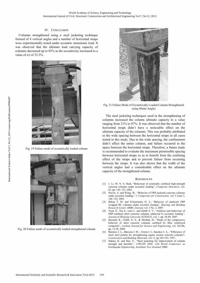
D. Strain in Vertical Angles
Fig. 15 shows the strain in the strengthening vertical angles
for column C4T3 strengthened using 3 straps and subjected to
eccentricity e/t=16.6%. Angle I on the eccentricity side
showed higher compressive strains than angle II on the
opposite side as shown in the figure. This of course is
attributed to the stress gradient caused by eccentricity. Similar
observations were noticed for the other specimens subjected to
World Academy of Science, Engineering and TechnologyInternational Journal of Civil, Structural, Construction and Architectural Engineering Vol:7, No:12, 2013
568International Scholarly and Scientific Research & Innovation 7(12) 2013
Inte
rnat
iona
l Sci
ence
Ind
ex V
ol:7
, No:
12, 2
013
was
et.o
rg/P
ublic
atio
n/99
9658
7
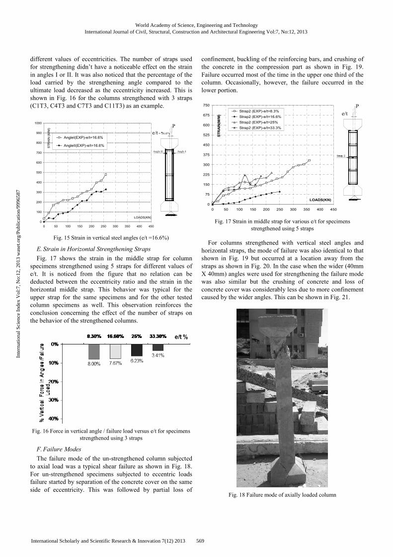
different values of eccentricities. The number of straps used
for strengthening didn’t have a noticeable effect on the strain
in angles I or II. It was also noticed that the percentage of the
load carried by the strengthening angle compared to the
ultimate load decreased as the eccentricity increased. This is
shown in Fig. 16 for the columns strengthened with 3 straps
(C1T3, C4T3 and C7T3 and C11T3) as an example.
0
100
200
300
400
500
600
700
800
900
1000
0 50 100 150 200 250 300 350 400 450
LOADS(KN)
ST
RA
IN (
M/M
)
AngleI(EXP)-e/t=16.6%
AngleII(EXP)-e/t=16.6%
Fig. 15 Strain in vertical steel angles (e/t =16.6%)
E. Strain in Horizontal Strengthening Straps
Fig. 17 shows the strain in the middle strap for column
specimens strengthened using 5 straps for different values of
e/t. It is noticed from the figure that no relation can be
deducted between the eccentricity ratio and the strain in the
horizontal middle strap. This behavior was typical for the
upper strap for the same specimens and for the other tested
column specimens as well. This observation reinforces the
conclusion concerning the effect of the number of straps on
the behavior of the strengthened columns.
Fig. 16 Force in vertical angle / failure load versus e/t for specimens
strengthened using 3 straps
F. Failure Modes
The failure mode of the un-strengthened column subjected
to axial load was a typical shear failure as shown in Fig. 18.
For un-strengthened specimens subjected to eccentric loads
failure started by separation of the concrete cover on the same
side of eccentricity. This was followed by partial loss of
confinement, buckling of the reinforcing bars, and crushing of
the concrete in the compression part as shown in Fig. 19.
Failure occurred most of the time in the upper one third of the
column. Occasionally, however, the failure occurred in the
lower portion.
0
75
150
225
300
375
450
525
600
675
750
0 50 100 150 200 250 300 350 400 450
LOADS(KN)
STRAIN(M/M)
Strap2 (EXP)-e/t=8.3%
Strap2 (EXP)-e/t=16.6%
Strap2 (EXP)-e/t=25%
Strap2 (EXP)-e/t=33.3%
Fig. 17 Strain in middle strap for various e/t for specimens
strengthened using 5 straps
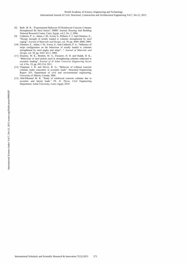
For columns strengthened with vertical steel angles and
horizontal straps, the mode of failure was also identical to that
shown in Fig. 19 but occurred at a location away from the
straps as shown in Fig. 20. In the case when the wider (40mm
X 40mm) angles were used for strengthening the failure mode
was also similar but the crushing of concrete and loss of
concrete cover was considerably less due to more confinement
caused by the wider angles. This can be shown in Fig. 21.
Fig. 18 Failure mode of axially loaded column
World Academy of Science, Engineering and TechnologyInternational Journal of Civil, Structural, Construction and Architectural Engineering Vol:7, No:12, 2013
569International Scholarly and Scientific Research & Innovation 7(12) 2013
Inte
rnat
iona
l Sci
ence
Ind
ex V
ol:7
, No:
12, 2
013
was
et.o
rg/P
ublic
atio
n/99
9658
7
IV. CONCLUSION
Columns strengthened using a steel jacketing technique
formed of 4 vertical angles and a number of horizontal straps
were experimentally tested under eccentric monotonic load. It
was observed that the ultimate load carrying capacity of
columns decreased up to 85% as the eccentricity increased to a
value of e/t of 33.3%.
Fig. 19 Failure mode of eccentrically loaded column
Fig. 20 Failure mode of eccentrically loaded strengthened column
Fig. 21 Failure Mode of Eccentrically Loaded Column Strengthened
using 40mm Angles
The steel jacketing techniques used in the strengthening of
columns increased the column ultimate capacity to a value
ranging from 21% to 87%. It was observed that the number of
horizontal straps didn’t have a noticeable effect on the
ultimate capacity of the columns. This was probably attributed
to the wide spacing between the horizontal straps in all cases
tested in this study. Due to the wide spacing, the confinement
didn’t affect the entire column, and failure occurred in the
space between the horizontal straps. Therefore, a future study
is recommended to evaluate the maximum permissible spacing
between horizontal straps so as to benefit from the confining
effect of the straps and to prevent failure from occurring
between the straps. It was also shown that the width of the
vertical angles had a considerable effect on the ultimate
capacity of the strengthened column.
REFERENCES
[1] J. Li, M. N. S. Hadi, “Behaviour of externally confined high-strength concrete columns under eccentric loading”, Composite Structures, vol.
62, pp. 145–153, 2003.
[2] Parvin, A. and Wang, W., “Behavior of FRP jacketed concrete columns under eccentric loading.” J. Composites for Construction, vol. 5 issue 3,
146–152, 2001.
[3] Bahaa T. M. and El-karmouty H. Z., “Behavior of sandwich FRP wrapped RC columns under eccentric loading”, Housing and Building Research Center, HBRC Journal, vol. 3 No. 2, 2007.
[4] Yuan X., Xia S., Lam L. and Smith S. T., “Analysis and behaviour of FRP-confined short concrete columns subjected to eccentric loading”,
Journal of Zhejiang University SCIENCE, vol. 1, pp. 38-49, 2007.
[5] Benzaid, R., Chikh, N. E., & Mesbah, H., “Study of the compressive behavior of short concrete columns confined by fiber reinforced
composite”, Arabian Journal for Science and Engineering, vol. 34(1B),
pp. 15-26, 2009. [6] Ramírez J. L., Bárcena J. M. , Urreta J. I., Sanchez J. A. , "Efficiency of
short steel jackets for strengthening square section concrete columns",
Construction and Building Materials, vol 11, pp 345-352, 1997. [7] Sakino, K. and Sun, Y., “Steel jacketing for improvement of column
strength and ductility”, 12WCEE 2000: 12th World Conference on Earthquake Engineering, Auckland, New Zealand, 2000.
World Academy of Science, Engineering and TechnologyInternational Journal of Civil, Structural, Construction and Architectural Engineering Vol:7, No:12, 2013
570International Scholarly and Scientific Research & Innovation 7(12) 2013
Inte
rnat
iona
l Sci
ence
Ind
ex V
ol:7
, No:
12, 2
013
was
et.o
rg/P
ublic
atio
n/99
9658
7
[8] Badr, M. R., "Experimental Behavoir Of Reinforced Concrete Columns
Strengthened By Steel Jacket", HBRC Journal, Housing And Building
National Research Center, Cairo, Egypt, vol.2, No. 2, 2006. [9] Calderón, P. A., Adam, J. M., Ivorra, S., Pallarés, F. J. And Giménez, E.,
"Design strength of axially loaded rc columns strengthened by steel
caging", Journal of Materials and Design, vol. 30, pp. 4069–4080, 2009. [10] Giménez, E., Adam, J. M., Ivorra, S., And Calderón, P. A., "Influence of
strips configuration on the behaviour of axially loaded rc columns
strengthened by steel angles and strips", ", Journal of Materials and Design, vol. 30, pp. 4103–4111, 2009.
[11] Elsamny, M. K., Ibrahim, M. A., Elesnawi, H. H. and Oudah, H. K.,
“Behaviour of steel jackets used in strengthening columns subjected to eccentric loading", Journal of Al Azhar Universty Engineering Sector
vol. 6 No. 19, pp. 493-514, 2011.
[12] Chapman, J. R. and Driver, R. G., “Behavior of collared concrete columns under concentric or eccentric loads”, Structural Engineering
Report 263, Department of civil and environmental engineering,
University of Alberta, Canada, 2006. [13] Abd-Elhamed M. K. “Study of reinforced concrete columns due to
eccentric and lateral loads” Ph. D. Thesis, Civil Engineering
Department, Azhar University, Cairo, Egypt, 2010.
World Academy of Science, Engineering and TechnologyInternational Journal of Civil, Structural, Construction and Architectural Engineering Vol:7, No:12, 2013
571International Scholarly and Scientific Research & Innovation 7(12) 2013
Inte
rnat
iona
l Sci
ence
Ind
ex V
ol:7
, No:
12, 2
013
was
et.o
rg/P
ublic
atio
n/99
9658
7