Embed Size (px)
Citation preview
Experimental study on gyroscopic effect of rotating rotor and windheading angle on floating wind turbine responses
Bahramiasl, S., Abbaspour, M., & Karimirad, M. (2017). Experimental study on gyroscopic effect of rotating rotorand wind heading angle on floating wind turbine responses. International Journal of Environmental Science andTechnology. https://doi.org/10.1007/s13762-017-1519-4
Published in:International Journal of Environmental Science and Technology
Document Version:Publisher's PDF, also known as Version of record
Queen's University Belfast - Research Portal:Link to publication record in Queen's University Belfast Research Portal
General rightsCopyright for the publications made accessible via the Queen's University Belfast Research Portal is retained by the author(s) and / or othercopyright owners and it is a condition of accessing these publications that users recognise and abide by the legal requirements associatedwith these rights.
Take down policyThe Research Portal is Queen's institutional repository that provides access to Queen's research output. Every effort has been made toensure that content in the Research Portal does not infringe any person's rights, or applicable UK laws. If you discover content in theResearch Portal that you believe breaches copyright or violates any law, please contact [email protected].
Download date:15. Mar. 2020
ORIGINAL PAPER
Experimental study on gyroscopic effect of rotating rotorand wind heading angle on floating wind turbine responses
S. Bahramiasl1 • M. Abbaspour1 • M. Karimirad2
Received: 22 October 2016 / Revised: 4 March 2017 / Accepted: 15 July 2017
� The Author(s) 2017. This article is an open access publication
Abstract Limited fossil resources, daily increasing rate of
demand for energy and the environmental pollution fact
have made people revert to renewable sources of energy as
a solution. One type of renewable energy is offshore wind
energy which has high potential without any sound and
visual noises. Recently, a lot of researchers have carried
out on the issue of offshore wind turbine. Because of
incapability of most of software programs to simulate
gyroscopic effect of rotating rotors, in this articles a sig-
nificant effort has been made to fabricate and test an off-
shore wind turbine under different rotor rotation velocities
and different heading angle of wind so as to obtain the
effects of these parameters on structure responses. Study on
the response of a wind turbine under environmental loads
has had a notable importance due to the fact that structure
behavior can strongly affect procedure of modeling and
optimizing wind turbine structures. On the other hand,
frequency-domain structural response of a wind turbine can
also make engineers be informed about of appropriate
mooring system for a special environmental condition.
Consequently, it has been observed that increasing the rotor
rotation velocity leads the peak of spectrums shift to a
higher frequency due to the gyroscopic effect appeared as a
damping term, and changing heading angle of wind may
lead to a change in heave and pitch amplitudes in the time
domain response, and heave, sway and surge motion in
frequency response.
Keywords Offshore wind turbine � Experimental study �Gyroscopic effect � Rotor rotation � Frequency domain
Introduction
Nowadays, environmental pollution of fossil fuels has
leaded many researchers to focus on renewable energy.
Among different types of renewable energy, offshore wind
has drawn attention of many researchers to itself due to
high potential of wind in offshore areas, whereas it has no
acoustic and optical noises. Offshore wind energy has been
found as an appropriate substitution to fulfill this demand.
It has conducted a lot of studies on the FOWT (Floating
Offshore Wind Turbine) responses in a variety of sea
conditions. Experimental investigation has been conducted
on a TLP FOWT with conical substructure moored by a
spring tension leg, subjected to the wave, wind and rotor
rotating loads (Shin 2011). The RAOs of structure motions
have been obtained and discussed. Their results have
shown that the new concept has had a good stability and
decent responses. Three types of FOWT, TLP, spar and
semisubmersible, have studied by a numerical time domain
approach which has been used for a fully coupled dynamic
analysis of FOWTs. Also, the mooring system of
semisubmersible equipped with six and eight mooring lines
has been investigated, and the platform rotations have been
compared along with motions (Bagbanci 2011). The
‘‘Hywind’’ turbine has been modeled by FAST code and
the results have been validated by experimental testing the
model. Also, the FAST ADAMS code has been used for
calculating the aerodynamic loads and WAMIT code has
Editorial responsibility: Necip Atar.
& M. Karimirad
1 School of Mechanical Engineering, Sharif University of
Technology, Tehran, Iran
2 Queen’s University Belfast (QUB), Belfast BT95AG, United
Kingdom
123
Int. J. Environ. Sci. Technol.
DOI 10.1007/s13762-017-1519-4
been used in order to calculate hydrodynamic loads
(Jonkman 2007; Browning et al. 2014). A TLP and a spar
type of FOWT have been modeled and tested experimen-
tally (Naqvi 2012). Preliminarily aerodynamic interaction
of flow and pitch structure responses has been studied by
using the time averaged unsteady Reynolds averaged
Navier–Stokes (URANS) method (Matha et al. 2011).
Gyroscopic effect of a FOWT has been investigated by
driving the equation of motion and calculating and adding
gyroscopic damping in the equation (Fujiwara et al. 2011).
A FOWT with a revolving disk on its top has been tested
and the responses of the platform with the rotating disk and
without it have been analyzed in frequency domain. Also,
the numerical studies have shown that the rotating disk
would induce an extra peak in yaw motion and shift peak of
surge and pitch motion to a higher frequency. Effect of
additional mooring chain on the response of a TLP FOWT
model with cylindrical and square support has been stud-
ied, and the responses of two different structures have been
obtained and discussed (Ren et al. 2012a, b). The results
have represented that the additional mooring would play an
active role in reducing surge motion, surge acceleration
and tension leg force responses of the structure.
The effect of gyroscopic couples on the response of a
semisubmersible FOWT has been investigated (Blusseau and
Patel 2012). The equations of motions in 6 DOFs (Degree Of
Freedom) have been formulated in frequency domain and
aerodynamic loads have been added and effect of gyroscopic
couples on the structure responses has been studied.
Dynamic response of a TLP FOWT has been numeri-
cally investigated under environmental loads (Ebrahimi
et al. 2014). The code has taken off-diagonal component of
stiffness, damping and mass matrices into account so as to
study the coupling of surge and pitch motions. For vali-
dating the numerical results, the 1:135 scaled-down model
has been tested in the laboratory. A 1:50 scaled model of
semisubmersible FOWT has been tested and investigated
in the wave-wind flume and the dynamic motions of the
structure have been analyzed (Hsu et al. 2016). Actually, a
solid disk has been used for simulating thrust force on the
wind turbine and natural frequency and damping coeffi-
cient have been obtained by free decay test. A unified
methodology for testing FROUDE scale models of FOWTs
has been presented and some methods have been suggested
for fabricating a high quality low turbulence FOWT in a
wave tank to simplify simultaneous application of wind
and waves to the model (Martin et al. 2012). A scaled
model of NREL (National Renewable Laboratory) 5 MW
wind turbine Matha (2010) has been tested and studied on
three different platforms TLP, spar and semisubmersible
and in same environmental loads in order to generate data
on coupled motions and loads between three platforms and
investigate advantageous and disadvantageous of each
platforms (Koo et al. 2014). A scaled model of NREL
5 MW wind turbine on three different platforms of TLP,
spar and semisubmersible have been experimentally stud-
ied in a large number of tests so as to study the coupled
system behavior of the three floating wind turbines sub-
jected to combined wind and wave environmental loads.
The results have demonstrated the unique advantages and
disadvantages of each floating wind turbine platform
(Goupee et al. 2014). The coupling effects created by
changes in the hydrodynamic behavior of a semisub-
mersible FOWT have been investigated when it subjected
to large inclinations under wind loads (Antonutti et al.
2016). They numerically have shown that the hull geo-
metric nonlinearity effect and the alteration of viscous
hydrodynamic forces can affect the dynamics of a typical
FOWT operating in waves at rated conditions.
Dynamic response of a 1:50 scaled-down model of OC3
spar FOWT has been experimentally investigated (Duan
et al. 2016). In the mentioned research, wind turbine blades
could freely rotate without any undesirable effect of con-
trolling wind turbine rotational speed.
A time domain numerical model of a braceless
semisubmersible FOWT has been calibrated against
experimental data of a 1:30 scaled model tested at MAR-
INTEK‘s ocean basin (Berthelsen et al. 2016). Actually
good agreements between simulations and experiments
have been obtained by adjustment the numerical model.
This adjustment was mainly related to the viscous drag
coefficient on the platform’s columns and pontoons.
There is a little research on the topic of experimental
study on gyroscopic effect of revolving blades of a TLP
FOWT on the structure motions. In this regard, the
objective of this research is experimental investigation on
the gyroscopic effect of rotating rotors and different wind
heading angles on response of a TLP FOWT. In the current
research, we have attempted to apply different environ-
mental loads, consist of wave and wind with different
headings, on the scaled FOWT and obtain the responses of
the model in six DOFs. Analyzing the results has given us
some notable information about effect of wind heading and
rotor rotation speeds on the response of the structure.
Materials and methods
Characteristics of the TLP FOWT
In this research, the platform of the FOWT has been a sea
star TLP and consisted of a single column equipped with
four spokes which have hold four vertical tendons. This
type of TLP platforms has been widely used in recent
studies (Ren et al. 2012a, b; Pinkster 1980; Gueydon et al.
2014). But in this research the system has been stiffed in
Int. J. Environ. Sci. Technol.
123
the vertical direction much more than other typical TLPs.
Due to the fact that for a model with this dimension no
perfect tendons has been found. In this regard, the men-
tioned TLP has been restrained in the vertical direction as
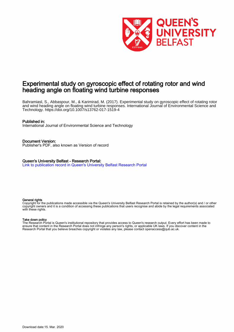
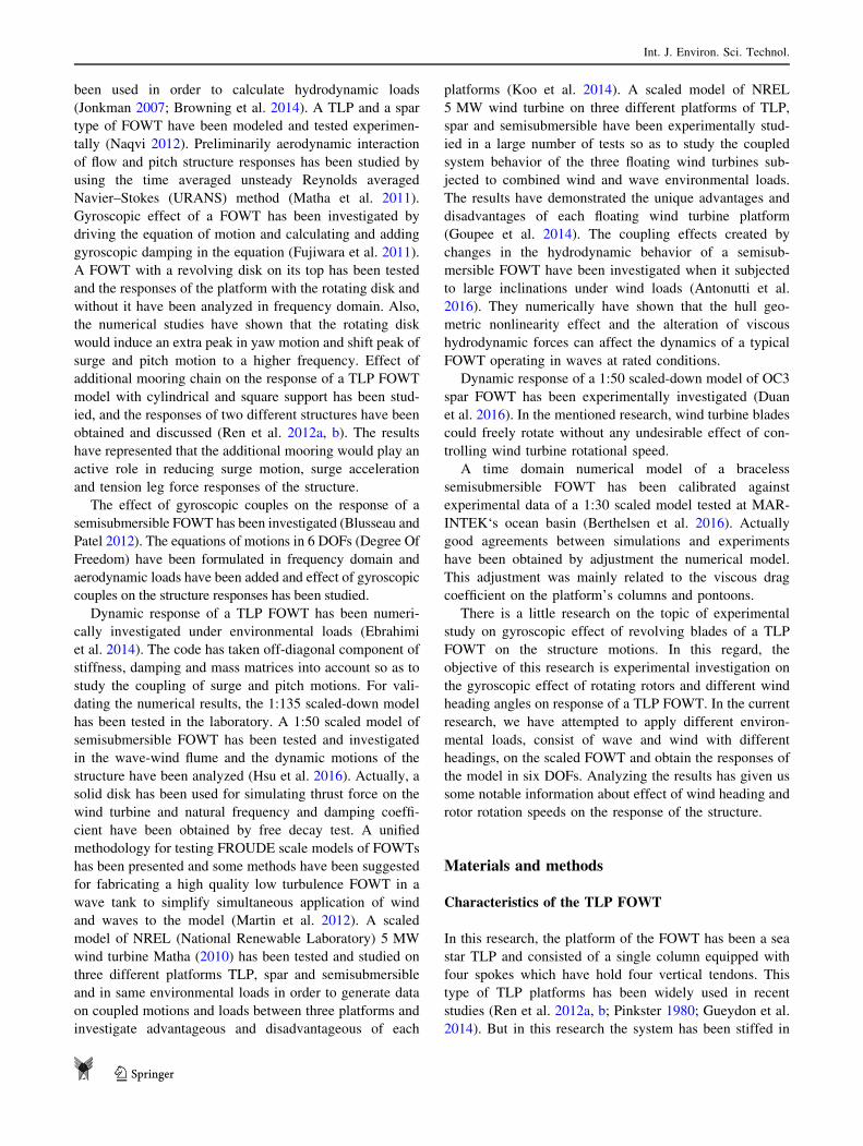
much as fixed platforms. Picture of the model installed to
the tank is presented in Fig. 1. The main geometric
parameters of the model have been demonstrated in
Table 1. The information about the added mass, added
inertia and hydrostatic stiffness of the platform which have
been represented in Table 1, have been calculated by using
former studies (Bachynski 2014; Karimirad et al. 2011).
Methods of obtaining gyroscopic effect
FOWTs work by gaining wind and rotation of their rotors.
Rotation of rotors causes gyroscopic effect on the structure.
The gyroscopic effect has been defined by Shilovskii: any
couple, apparently tending to incline the axis of the rotating
body in a given direction, actually causes an inclination of
the axis in the plane perpendicular to that given direction
(Shı̄lovskı̄ı̌ 1924; Gray 1918). The gyroscopic effect will be
in every system which has a revolving part. Equation of
motion of the TLP FOWT can be driven from Newton’s
second law, and written as below:
F tð Þ ¼ M½ � þ A½ �ð Þ€xþ C½ � þ Cg
� �� �_xþ k½ �x ð1Þ
where [M], [A], [C] and [k] are, respectively, mass
matrix, added mass matrix, damping matrix and total
stiffness matrix and F(t) is environmental loads applied
to the structure which consists of wave, wind and
aerodynamic loads. Also, Cg
� �is damping matrix which
is caused by revolving of rotors (Fujiwara et al. 2011;
Blusseau and Patel 2012). As respect to past studies, an
operating wind turbine will induce extra damping (in
rotational degrees of freedom except the one is align to
the turbine’s axis) and this extra damping can be defined
by use of gyroscopic reaction moment using d’alembert
principle:
Lp ¼ Ipxp � ip ð2Þ
where Ip is angular momentum, xp is constant rotation
velocity and Lp is gyroscopic reaction moment.
� dLp
dt¼ �Ipxp �
dip
dt¼ �IpxpX� ip ð3Þ
In above equation, X is angular velocity vector and can be
expressed as below (Fujiwara et al. 2011):
X � Re �ix X4;X5;X6ð Þe�ixt� �
ð4Þ
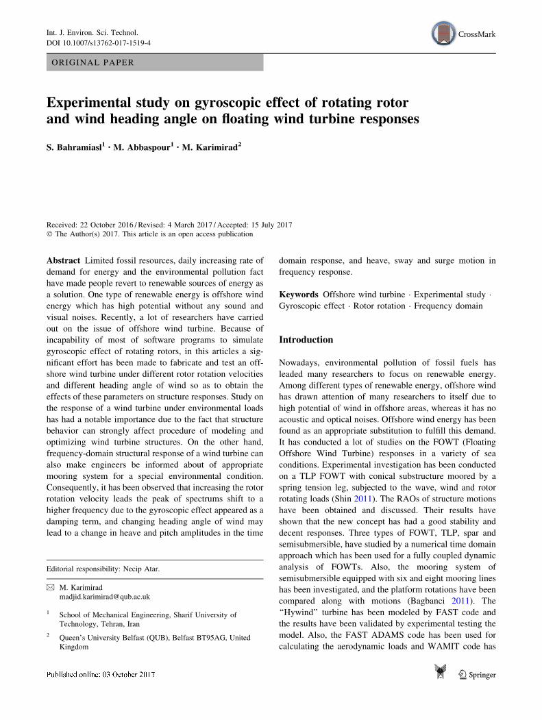
where X4;X5;X6 are, respectively, the rotational angles
about x, y, z axes according to Fig. 2a. And x the circular
frequency of body motion equal to one of the incident wave.
Finally by substitution Eqs. 4 in 3, the following equa-
tion will be formed.
� dLp
dt¼ �IpxpRe �ix X4;X5;X6ð Þe�ixt
� �� ip ð5Þ
In the case of horizontal axis wind turbines, the unit vector
is ip ¼ 1; 0; 0ð Þ and former equation can be represented as
the following form:
� dLp
dt¼ IpxpxRe i 0;X6;�X5ð Þe�ixt
� �ð6Þ
Equation 6 expresses the relation between rotation of
rotating object and damping term in the equation of
motion. Equation 7 shows the mentioned gyroscopic
damping coefficient matrix.
Cg ¼Ipxp
qg�
0 0 0 0 0 0
0 0 0 0 0 0
0 0 0 0 0 0
0 0 0 0 0 0
0 0 0 0 0 �1
0 0 0 0 1 0
2
6666664
3
7777775
ð7Þ
Fig. 1 a Tensioned legs of model, b model installed in the tank,
c model subjected in wave and wind loads
Int. J. Environ. Sci. Technol.
123
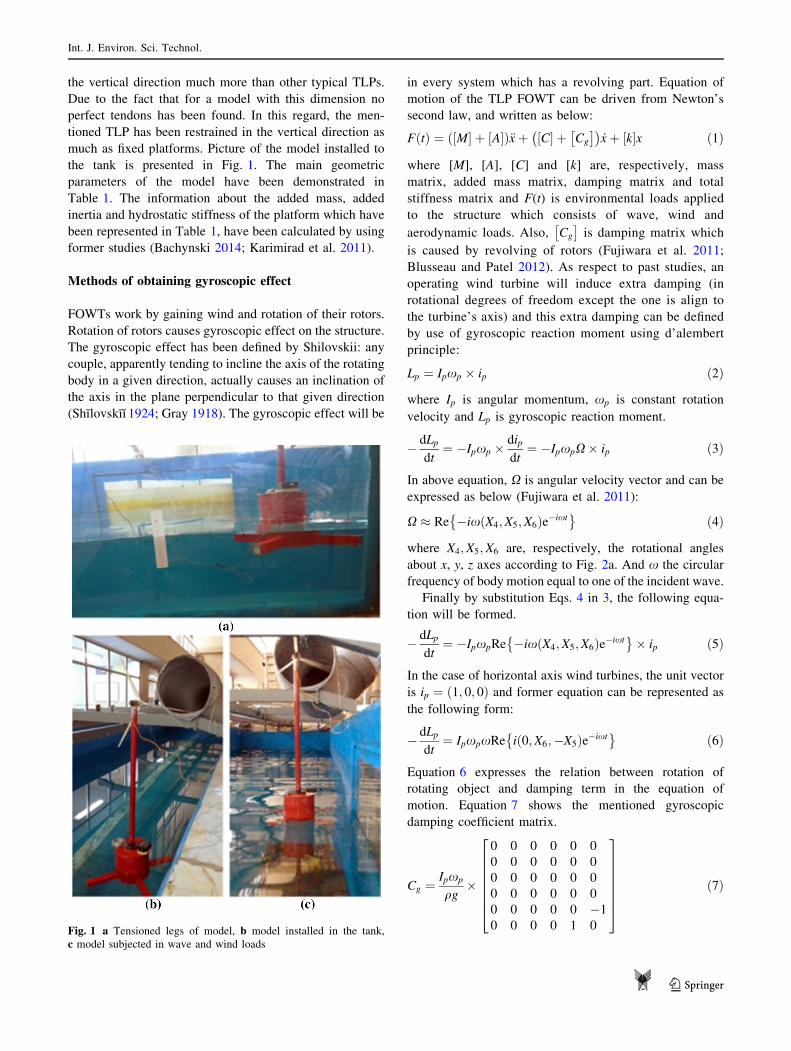
Fig. 2 a Coordinate system of FOWT, b a sketch of experimental setup of test in plane view
Table 1 Characteristics of the
platform and mooring linesParameter Full scaled Scale factor Scaled model
Cylinder radius (m) 10 k 0.10
Cylinder height (m) 20 k 0.20
Total weight (kg) 2,500,000 k3 2.50
Total buoyancy (kg) 4,000,000 k3 4.00
Design depth (m) 100 k 1
Hub diameter (m) 3 k 0.03
Rotor diameter (m) 60 k 0.60
Hub height (m) 90 k 0.90
Characteristics of the mooring lines
Vertical distance of cable 90 k 0.90
Cable area (m2) 3.8 E-3 k2 3.8 E-7
Cable young module (N/m2) 1.99 E?13 k 1.99 E?11
Pretension (N) 3.08E?7 k3 30.80
Unstretched length (m) 89 k 0.89
Hydrostatic characteristics of the platform
A11 (kg) 2.45 k3 2,450,560
A33 (kg) 1.59 k3 1,592,786.7
I55 (kg) 1000 k4 1e9
Ixx–Iyy 3.75 E?9 k5 0.375
Izz 2.14 E?8 k5 0.0214
kh platform (N/m) 308.03 k2 3,080,340
kp platform (N/m) 2.45 k2 2,450,560
Int. J. Environ. Sci. Technol.
123
By inserting this gyroscopic damping term in Eq. 1 and
rearranging it, the following form of equation of motion
can be obtained.
F tð Þ ¼ M½ � þ A½ �ð Þ€xþ k½ �x
þ C½ � þ Ipxp
qg�
0 0 0 0 0 0
0 0 0 0 0 0
0 0 0 0 0 0
0 0 0 0 0 0
0 0 0 0 0 �1
0 0 0 0 1 0
2
6666664
3
7777775
0
BBBBBB@
1
CCCCCCA
_x1_x2_x3_x4_x5_x6
2
666664
3
777775
ð8Þ
From Eq. 8, it can be concluded that gyroscopic
damping coefficient is proportional to moment of inertia
and velocity of rotation of the revolving part.
Consequently, the rotation of the blades can influence
response of the structure due to the mentioned extra
damping term.
Methods of calculating natural frequency
of the system
The natural frequency of each motion for the TLP FOWT
can be defined as below (Shı̄lovskı̄ı̌ 1924):
xn ¼ffiffiffiffiffiffiffiffiffiffiffiffiffi
k
M þ A
r
ð9Þ
where k is stiffness in the specified motion, M is the mass
and A is added mass in the mentioned motion. The equation
can be extended for heave, surge, and pitch motions as
below.
xSurge ¼ffiffiffiffiffiffiffiffiffiffiffiffiffiffiffiffiffikSurge
M þ A11
r
ð10Þ
kSurge ¼ kstether ¼ 4� T0
Lð11Þ
where xSurge is the natural frequency in surge motion, kSurgeis total stiffness for surge motion, A11 is the surge added
mass, kstether is stiffness of each tether in surge motion, T0 is
the pretension of each tether and L is length of the tethers.
xheave ¼ffiffiffiffiffiffiffiffiffiffiffiffiffiffiffiffiffikheave
M þ A33
r
ð12Þ
kheave ¼ kh platform þ kh tether ð13Þ
kh platform ¼ qgAc ð14Þ
kh tether ¼ 4� AtE
Lð15Þ
In above equations, xheave is the natural frequency for
heave, kh platform is heave hydrostatic stiffness, kh tether is the
tether stiffness for heave motion, A33 is the heave added
mass, Ac is area of the platform in the water level, q is the
water density, g is the gravity acceleration, At is tether
section area and E is the elasticity modulus of the tethers.
xPitch ¼ffiffiffiffiffiffiffiffiffiffiffiffiffiffiffikPitch
Ip þ I55
s
ð16Þ
kPitch ¼ kp platform þ kp tether ð17Þ
kp platform ¼ qgrKB�MgKGþ qgI ð18Þ
kp tether ¼T0
LKGþ Lð ÞKG ð19Þ
where xPitch is the natural frequency for pitch, Ip and I55are, respectively, pitch inertia and added pitch inertia,
kp platform is pitch hydrostatic stiffness, kp tether is the tether
stiffness for pitch motion, A55 is the pitch added mass,r is
the submerged volume, KB and KG are, respectively,
distance of the center of buoyancy and center of gravity
from bottom of the platform and I is the area moment of
inertia.
According to all characteristics which have been rep-
resented in the Table 1 and all mentioned equations, the
natural frequencies of the system have been calculated as
below.
xSurge ¼ 0:52 ð20Þ
xHeave ¼ 28:29 ð21ÞxPitch ¼ 0:33 ð22Þ
Methods of calculating second-order wave loads
For calculating both sum and diffraction frequency second-
order loads on the TLP FOWT, the pressure integration
approach has been used and according to former studies,
the equation of sum-frequency second order has been
represented as the following form (Chen and Molin 1990):
F22 2xð Þ!
¼ 2ixqg
ZZ
z¼0
aD:URð2xÞdS ð23Þ
where F22 is the exciting force, aD is the right-hand side of
free surface equation and UR is radiation potential at the
double frequency, 2x. The equation of diffraction
frequency second order has been represented as below
(Pinkster 1980; Gueydon et al. 2014):
F 2ð Þ! ¼ 1
2qg
ZZ
W:L:
f21ð Þ�rel � n0!� dl!þ 1
2qZZ
S
r/ 1ð Þ � r/ 1ð Þ � n0!dS
þZZ
S
qX 1ð Þ � ro/ 1ð Þot
� n0!dSþ X 1ð Þ!�M � X 1ð Þ
!
� qZZ
S
o/ 2ð Þot
� n0!dS
ð24Þ
Int. J. Environ. Sci. Technol.
123
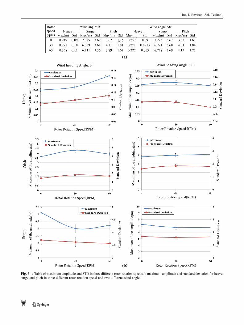
Fig. 3 a Table of maximum amplitude and STD in three different rotor rotation speeds, b maximum amplitude and standard deviation for heave,
surge and pitch in three different rotor rotation speed and two different wind angle
Int. J. Environ. Sci. Technol.
123
In the above equation, Subscript (1) denotes when a
quantity is of the first order and (2) denotes when a quantity
is of the second order. And f:rel is relative wave elevation,
W.L. is water line, n0 is the outward pointing normal
vector, dl is element of water line vector, / is the velocity
potential, dS is the surface element of the wetted hull and Xis the angular motion vector.
Wave-wind tank
The experiment has been carried out in the Marine labo-
ratory of Sharif University. The tank dimension is
22.5 m 9 2.5 m with the depth of 1.2 m. The paddle-type
wave generator is able to generate waves with the height
range of 0.01–0.08 m and 0.5–1.5 s periods (Sarlak et al.
2010). The wind generator consists of an axial fan and an
inverter in order to control the input electric current,
rotational speed of fan’s blades and consequently, the
output wind speed. The wind generator is able to generate a
maximum wind speed of 30 m/s. A schematic of the
experimental setup of test is shown in Fig. 2b.
The wind generator is stand on its legs which are out of
the tank and the generated wind is guided to the model by a
duct. The speed of the generated wind subjected to model
has been measured during the tests by a wind speed meter
with the accuracy of ±3% and measurement speed range of
0–30 m/s. The wind around the wind turbine has not been
completely uniform and has had a little turbulent which has
caused some negligible tower’s oscillation. Due to low
laboratory equipment, the generated wind has been con-
sidered as a uniform constant wind.
Actually, in order to rotate the blades and hub with the
desired speed, a power supply and an armature has been
utilized.
Scaled model
Platform design
In this research, a sea star TLP for depth of 100 m, have
been designed as the platform of the FOWT. Actually, the
structure has been consisted of a single column equipped
with four spokes which have hold four vertical tendons.
This type of TLP platforms has been widely used in recent
studies (Ren et al. 2012a, b; Pinkster 1980; Gueydon et al.
2014). The Froude-scaled model of the TLP FOWT has
been fabricated in the marine Laboratory of Sharif
University of Technology. The platform model has been
constituted of a polycarbonate PVC cylinder and four
aluminum alloy profiles for its spokes and they have been
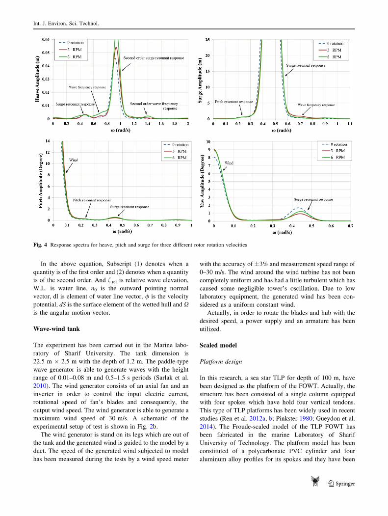
Fig. 4 Response spectra for heave, pitch and surge for three different rotor rotation velocities
Int. J. Environ. Sci. Technol.
123
latched to each other. The tower has been consisted of a
PVC pipe with a hub and blades on its top and has been
connected and fixed to the platform. The ratio of model to
prototype is 1/100 based on the Froude Number (Crozier
2011; Chakrabarti 1998). This model has been tested in the
towing tank of Sharif University in order to study the
gyroscopic effects and the heading of wind on the platform
response of FOWT, and obtaining spectrums of significant
motions.
In order to make the model in detail and minimize the
errors, a significant effort has been made and the model has
been produced three times to have minimum error in
geometry. In order to best assessment of center of gravity,
weight of all components of the model has been measured
and due to their location on the model, the center of gravity
has been obtained.
Rotors and blades design
The hub and rotors have been scaled based on the Froude
number (Chakrabarti 1998; Chanson 2004) and have been
constructed with detail of 0.1 mm by a 3D printer. A
particular care has been taken in selecting material and
fabricating the blades. The blades and the hub have been
latched to each other carefully without any slip.
Due to the friction between hub and connecting shaft to
the tower, the rotors have not moved by blowing the wind
to the model. Consequently, in this research the rotors have
been revolved by a power supply and an armature. In this
regard, the performance of the model has been different to
the full-scaled wind turbine. But due to the lack of suffi-
cient information about downstream wind, finding char-
acteristics of the scaled rotors have become impossible.
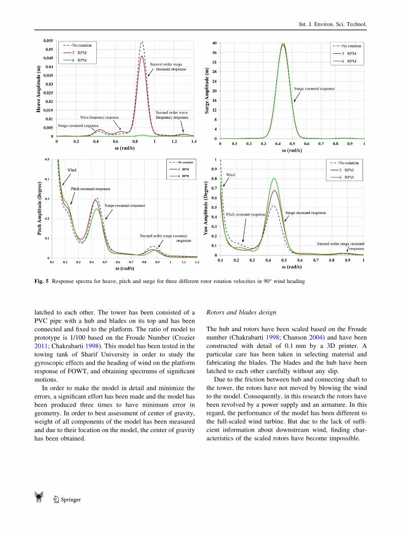
Fig. 5 Response spectra for heave, pitch and surge for three different rotor rotation velocities in 90� wind heading
Int. J. Environ. Sci. Technol.
123
Mooring line
As respect of enormous aerodynamic load acting on the
turbine, the mooring system of the model has a significant
importance on dynamic response of the platform. Since the
mooring lines of the platform have been long slender
bodies and their stiffness have played a significant role in
their responses so the moorings have been scaled due to the
Cauchy Number (Chanson 2004). The main parameters of
the mooring system have been presented in the Table 1. In
order to construct the mooring lines as accurately as pos-
sible, four steel wires which has had 0.7 mm diameter,
have been used and connected to the model and bed of the
tank.
Calibration and test condition
A notable number of tests have been performed so as to
evaluate the gyroscopic effect and wind heading angle
effect, on the different platform motions. In all the tests
characteristics of the wind and wave have been scaled
down by the Froude Number (Chakrabarti 1998; Chanson
2004). Consequently, three different scenarios have been
pursued in this research. The first one is studying gyro-
scopic effect of rotor rotation speed on the structure
responses. For this purpose, tests with same wave and wind
characteristics and different in rotor rotation velocities
have been performed.
The second scenario is obtaining effect of heading angle
of wind on the structure responses. In this regard, tests with
same characteristics and different wind headings, 0, 30, 60,
90 toward the model, have been carried out.
Finally, the last one is studying effect of different sea
states on heave, surge and pitch motions. In order to do so,
six different sea states have been applied to the model and
their results have been captured and analyzed.
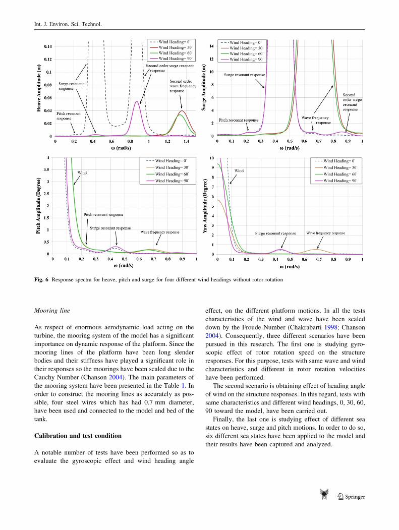
Fig. 6 Response spectra for heave, pitch and surge for four different wind headings without rotor rotation
Int. J. Environ. Sci. Technol.
123
Results and discussion
Gyroscopic effect of rotors rotation
An operating wind turbine has excited extra loads on the
structure and it has leaded a change in spectrum of platform
motions. For attaining effect of rotor rotation velocity on
the structure responses, in a constant wave and wind loads,
3 different rotor rotation speeds, 0, 30 and 60 rpm have
been applied to the model with constant regular wave with
0.03 m height and 1 s period. This set of tests has been
divided into two parts. In the first part, heading angle of
wind related to the model was 0�. The result of tests has
been scaled up and shown in Figs. 3b and 4.
By analyzing time response results, it can be deduced
that the most sensitive motion to the rotor speed can be the
heave motion in wind angle of 00. Figure 3a represents the
standard deviation and maximum amplitude of heave,
surge and pitch motions in different rotor speeds. Also,
these results are shown in Fig. 3b. Also, effect of wind can
be seen in the pitch and yaw spectrum as well (Chanson
2004).
Besides, the experimental results have represented that
in the heave, surge, pitch and yaw spectrums, rotation of
rotors has shifted the peak of curve to a higher frequency
due to the fact that rotation of blades has induced an extra
damping in the equation of motion, which has been dis-
cussed in the theoretical background section in Eq. 8.
Addition to this, amplifying of the peak in the heave
spectrum can be seen as well.
In the next part of this section, the tests have repeated
once again but in 90� wind heading angle for obtaining the
result of structure responses in 90� angle of wind.
The results have shown that when the wind heading
angle is 90� the movement of peak observed in the last part,
has become very slight. In the heave spectrum, the curve
for 60 rpm rotation speed has tended to a horizontal line
(Fig. 5).
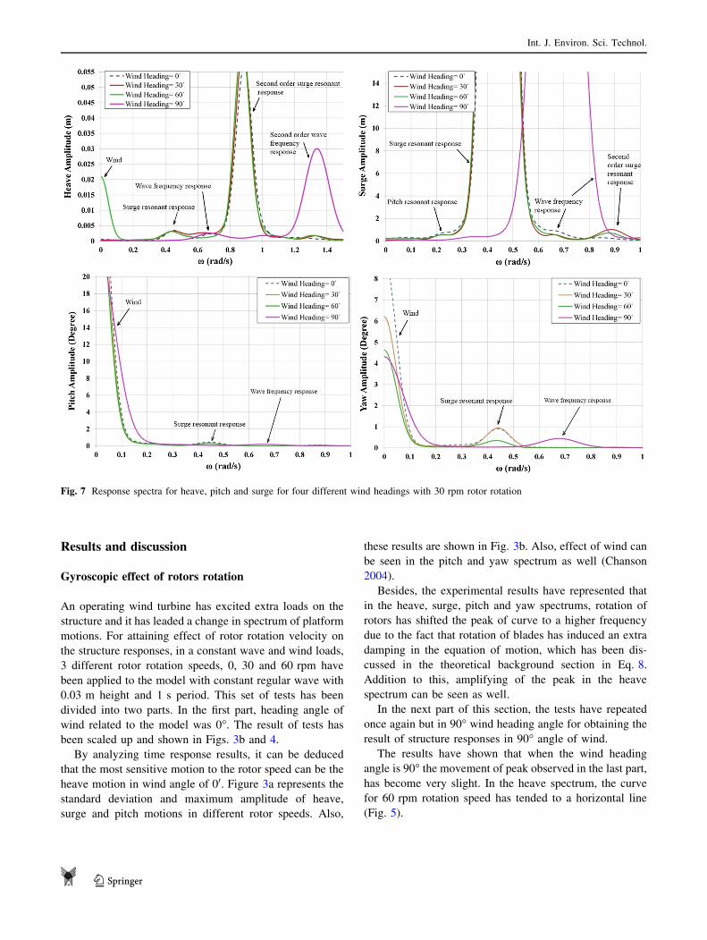
Fig. 7 Response spectra for heave, pitch and surge for four different wind headings with 30 rpm rotor rotation
Int. J. Environ. Sci. Technol.
123
Also, in the mentioned figures in this section, double
frequencies of wave and surge motion which have been
induced according to Eqs. 23 and 24 can be observed.
Effect of wind heading on structure responses
For studding the effect of wind heading angle on the
structure responses, in a constant wave and wind loads,
four different wind heading angles, 0�, 30�, 60� and 90�have been applied to the model with constant regular wave
with 0.03 m height and 1 s period. Actually, this section
has been divided into three parts which have been distin-
guished from each other by the speed of rotor criteria.
In the first part of this section, tests with no rotor rota-
tion have been carried out. The results have demonstrated
that heave and yaw behavior in 0� and 90� wind headings
have been similar and on the other hand, the 30� and 60�
headings have done so. And in the surge and pitch, the 30�and 60� headings have been shifted to higher frequency
(Fig. 6).
In the next part, the mentioned tests have been done with
30 rpm rotor rotational speed. Figure 7 shows the structure
spectrums for these tests. In the heave and surge spectrums,
all headings except 90� heading have had the same
behavior. But in the pitch and yaw, spectrums all headings
have been similar to each other.
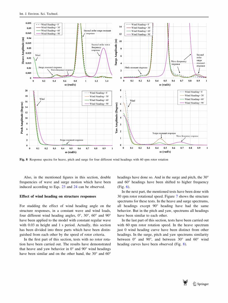
In the last part of this section, tests have been carried out
with 60 rpm rotor rotation speed. In the heave spectrum
just 0 wind heading curve have been distinct from other
headings. In the surge, pitch and yaw spectrums similarity
between 0� and 90�, and between 30� and 60� wind
heading curves have been observed (Fig. 8).
Fig. 8 Response spectra for heave, pitch and surge for four different wind headings with 60 rpm rotor rotation
Int. J. Environ. Sci. Technol.
123
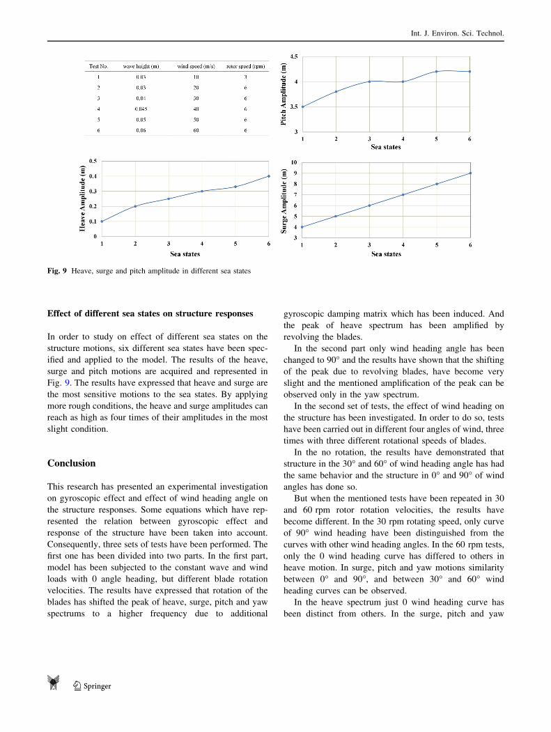
Effect of different sea states on structure responses
In order to study on effect of different sea states on the
structure motions, six different sea states have been spec-
ified and applied to the model. The results of the heave,
surge and pitch motions are acquired and represented in
Fig. 9. The results have expressed that heave and surge are
the most sensitive motions to the sea states. By applying
more rough conditions, the heave and surge amplitudes can
reach as high as four times of their amplitudes in the most
slight condition.
Conclusion
This research has presented an experimental investigation
on gyroscopic effect and effect of wind heading angle on
the structure responses. Some equations which have rep-
resented the relation between gyroscopic effect and
response of the structure have been taken into account.
Consequently, three sets of tests have been performed. The
first one has been divided into two parts. In the first part,
model has been subjected to the constant wave and wind
loads with 0 angle heading, but different blade rotation
velocities. The results have expressed that rotation of the
blades has shifted the peak of heave, surge, pitch and yaw
spectrums to a higher frequency due to additional
gyroscopic damping matrix which has been induced. And
the peak of heave spectrum has been amplified by
revolving the blades.
In the second part only wind heading angle has been
changed to 90� and the results have shown that the shifting
of the peak due to revolving blades, have become very
slight and the mentioned amplification of the peak can be
observed only in the yaw spectrum.
In the second set of tests, the effect of wind heading on
the structure has been investigated. In order to do so, tests
have been carried out in different four angles of wind, three
times with three different rotational speeds of blades.
In the no rotation, the results have demonstrated that
structure in the 30� and 60� of wind heading angle has had
the same behavior and the structure in 0� and 90� of windangles has done so.
But when the mentioned tests have been repeated in 30
and 60 rpm rotor rotation velocities, the results have
become different. In the 30 rpm rotating speed, only curve
of 90� wind heading have been distinguished from the
curves with other wind heading angles. In the 60 rpm tests,
only the 0 wind heading curve has differed to others in
heave motion. In surge, pitch and yaw motions similarity
between 0� and 90�, and between 30� and 60� wind
heading curves can be observed.
In the heave spectrum just 0 wind heading curve has
been distinct from others. In the surge, pitch and yaw
Fig. 9 Heave, surge and pitch amplitude in different sea states
Int. J. Environ. Sci. Technol.
123

spectrums the 0� and 90�, and between 30� and 60� wind
heading curves have had same behavior as well as first part
of this section.
Finally, in the last part of the research, effect of different
sea states on the heave, surge and pitch motions has been
studied. It has been observed that the most sensitive
motions to the sea states are heave and surge motions.
By taking into account all above-mentioned observa-
tions, it can be concluded that rotation of blades of a
FOWT can affect position of the peak of spectrums but
inclination of wind heading may reduce it. Actually, wind
heading angle may change behavior of spectrums which
can be affected by rotor velocity as well.
Acknowledgement The authors want to thank staff of Marine labo-
ratory of Sharif University of Technology for helping producing the
model and accomplishing tests.
Open Access This article is distributed under the terms of the
Creative Commons Attribution 4.0 International License (http://
creativecommons.org/licenses/by/4.0/), which permits unrestricted
use, distribution, and reproduction in any medium, provided you give
appropriate credit to the original author(s) and the source, provide a
link to the Creative Commons license, and indicate if changes were
made.
References
Antonutti R, Peyrard C, Johanning L, Incecik A, Ingram D (2016) The
effects of wind-induced inclination on the dynamics of semi-
submersible floating wind turbines in the time domain. Renew
Energy 88:83–94
Bachynski EE (2014) Design and dynamic analysis of tension leg
platform wind turbines, Doktoravhandlinger ved NTNU,
1503-8181; 2014:86, PhD thesis, NTNU, Trondheim, Norway
Bagbanci H (2011) Dynamic analysis of offshore floating wind
turbines. Naval Architecture and Marine Engineering, Technical
University of Lisbon
Berthelsen PA, Bachynski EE, Karimirad M, Thys M (2016) Real-
time hybrid model tests of a braceless semi-submersible wind
turbine. Part III: calibration of a numerical model. In: Proceed-
ings of the ASME 2016 35th international conference on ocean,
offshore and arctic engineering OMAE2016 June 19–24, 2016,
Busan, Korea
Blusseau P, Patel MH (2012) Gyroscopic effects on a large vertical
axis wind turbine mounted on a floating structure. Renew Energy
46:31–42
Browning JR, Jonkman J, Robertson A, Goupee AJ (2014) Calibration
and validation of a spar-type floating offshore wind turbine model
using the FAST dynamic simulation tool. In: Journal of physics:
conference series, vol. 555, no. 1. IOP Publishing, p 012015
Chakrabarti S (1998) Physical model testing of floating offshore
structures. In: Dynamic positioning conference
Chanson H (2004) Hydraulics of open channel flow. Butterworth-
Heinemann, Oxford
Chen XB, Molin B (1990) High frequency interactions between TLP
legs. In: 5th international workshop on water wavesand floating
bodies
Crozier A (2011) Design and dynamic modeling of the support
structure for a 10 MW offshore wind turbine, MSc thesis,
NTNU, Trondheim, Norway
Duan F, Hu Z, Niedzwecki JM (2016) Model test investigation of a
spar floating wind turbine. Mar Struct 49:76–96
Ebrahimi A, Abbaspour M, Nasiri RM (2014) Dynamic behavior of a
tension leg platform offshore wind turbine under environmental
loads. Sci Iran Trans A Civ Eng 21(3):480
Fujiwara H, Tsubogo T, Nihei Y (2011) Gyro effect of rotating blades
on the floating wind turbine platform in waves. In: The twenty-
first international offshore and polar engineering conference.
International Society of Offshore and Polar Engineers
Goupee AJ, Koo BJ, Kimball RW, Lambrakos KF, Dagher HJ (2014)
Experimental comparison of three floating wind turbine con-
cepts. J Offshore Mech Arct Eng 136(2):020906
Gray A (1918) A treatise on gyrostatics and rotational motion: theory
and applications. Macmillan and Company limited, New York
Gueydon S, Duarte T, Jonkman J (2014) Comparison of second-order
loads on a semisubmersible floating wind turbine. In: ASME
2014 33rd international conference on ocean, offshore and arctic
engineering. American Society of Mechanical Engineers, pp
V09AT09A024–V09AT09A024
Hsu WY, Yang RY, Chang FN, Wu HT, Chen HH (2016)
Experimental study of floating offshore platform in combined
wind/wave/current environment. Int J Offshore Polar Eng
26(02):125–131
Jonkman JM (2007) Dynamics modeling and loads analysis of an
offshore floating wind turbine. ProQuest, Ann Arbor
Karimirad M, Meissonnier Q, Gao Z, Moan T (2011) Hydroelastic
code-to-code comparison for a tension leg spar-type floating
wind turbine. Mar Struct 24(4):412–435
Koo BJ, Goupee AJ, Kimball RW, Lambrakos KF (2014) Model tests
for a floating wind turbine on three different floaters. J Offshore
Mech Arct Eng 136(2):020907
Martin HR, Kimball RW, Viselli AM, Goupee AJ (2012) Method-
ology for wind/wave basin testing of offshore floating wind
turbines. In: Proceedings of the ASME
Matha D (2010) Model development and loads analysis of an offshore
wind turbine on a tension leg platform with a comparison to
other floating turbine concepts: April 2009 (No. NREL/SR-500-
45891). National Renewable Energy Laboratory (NREL),
Golden
Matha D, Schlipf M, Pereira R, Jonkman J (2011) Challenges in
simulation of aerodynamics, hydrodynamics, and mooring-line
dynamics of floating offshore wind turbines. In: The twenty-first
international offshore and polar engineering conference. Inter-
national Society of Offshore and Polar Engineers
Naqvi SK (2012) Scale model experiments on floating offshore wind
turbines. Doctoral dissertation, Worcester Polytechnic Institute
Pinkster JA (1980) Low frequency second order wave exciting forces
on floating structures. Doctoral dissertation, TU Delft, Delft
University of Technology
Ren N, Li Y, Ou J (2012a) The effect of additional mooring chains on
the motion performance of a floating wind turbine with a tension
leg platform. Energies 5(4):1135–1149
Ren N, Li Y, Ou J (2012b) The wind-wave tunnel test of a new
offshore floating wind turbine with combined tension leg-
mooring line system. In: The twenty-second international
Int. J. Environ. Sci. Technol.
123

offshore and polar engineering conference. International Society
of Offshore and Polar Engineers
Sarlak H, Seif MS, Abbaspour M (2010) Experimental investigation
of offshore wave buoy performance. Int J Marit Technol (IJMT)
6(11):1–11
Shı̄lovskı̄ı̌ PP (1924) The gyroscope: its practical construction and
application: treating of the physics and experimental mechanics
of the gyroscope, and explaining the methods of its application to
the stabilization of monorailways, ships, aeroplanes, marine
guns, etc. E. & FN Spon, Limited, London
Shin H (2011) Model test of the OC3-Hywind floating offshore wind
turbine. In: The twenty-first international offshore and polar
engineering conference. International Society of Offshore and
Polar Engineers
Int. J. Environ. Sci. Technol.
123