Embed Size (px)
Citation preview
Explosion-Proof Drivesto EU Directive 94/9/EC
Edition
02/2003
Drive Engineering – Practical Implementation1056 0211 / EN


Practical Engineering - Explosion-Proof Drives to EU Directive 94/9/EG 3
Contents
1 Purpose of Explosion Protection..................................................................... 4
2 Purpose of this Documentation....................................................................... 5
3 Explosion Protection in Europe Today and Tomorrow ................................ 63.1 Useful Internet addresses ......................................................................... 7
4 The New Protection Concept ........................................................................... 84.1 Overview of EU Directive 94/9/EC ............................................................ 84.2 Overview of EU Directive 1999/92/EC .................................................... 11
5 Drives to EU Directive 94/9/EC....................................................................... 135.1 Conformity evaluation ............................................................................. 135.2 EC-type examination............................................................................... 135.3 Production quality assurance.................................................................. 145.4 Internal control of production .................................................................. 145.5 Declaration of conformity and CE marking.............................................. 145.6 Designation key for explosion-proof equipment ...................................... 155.7 Mechanical equipment according to EU Directive 94/9/EC..................... 175.8 Required accompanying documentation................................................. 18
6 Gas Explosion Protection............................................................................... 196.1 Categorization......................................................................................... 196.2 Protection types ...................................................................................... 206.3 Protection type “e” standard for AC motors in zone 1 ............................. 236.4 Special features of speed-controlled AC motors..................................... 26
7 Dust Explosion Protection ............................................................................. 287.1 Characteristic values for dust explosion protection in accordance with
EN50281-1-1:1998.................................................................................. 297.2 New zone classification according to EC Directive 1999/92/EC ............. 327.3 Standards / design regulations for dust explosion protection.................. 33
8 Application Examples..................................................................................... 348.1 Transportation of sacks / standard operating conditions......................... 348.2 Transportation of sacks / zone 22........................................................... 368.3 Transportation of sacks / zone 1............................................................. 38
9 Service and Maintenance ............................................................................... 399.1 General maintenance.............................................................................. 409.2 Special maintenance............................................................................... 40
10 A Comparison of Foreign Regulations.......................................................... 4110.1 North American regulations..................................................................... 41
11 Overview of Standards ................................................................................... 4311.1 Figures .................................................................................................... 43
12 List of References ........................................................................................... 44
13 Glossary........................................................................................................... 45
1
4
urpose of Explosion Protection
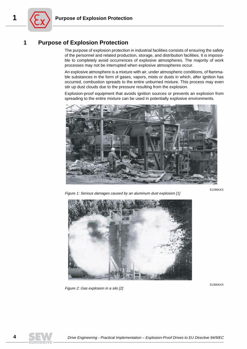
1 Purpose of Explosion ProtectionThe purpose of explosion protection in industrial facilities consists of ensuring the safetyof the personnel and related production, storage, and distribution facilities. It is impossi-ble to completely avoid occurrences of explosive atmospheres. The majority of workprocesses may not be interrupted when explosive atmospheres occur.
An explosive atmosphere is a mixture with air, under atmospheric conditions, of flamma-ble substances in the form of gases, vapors, mists or dusts in which, after ignition hasoccurred, combustion spreads to the entire unburned mixture. This process may evenstir up dust clouds due to the pressure resulting from the explosion.
Explosion-proof equipment that avoids ignition sources or prevents an explosion fromspreading to the entire mixture can be used in potentially explosive environments.
51299AXXFigure 1: Serious damages caused by an aluminum dust explosion [1]
51300AXXFigure 2: Gas explosion in a silo [2]
P
Drive Engineering - Practical Implementation – Explosion-Proof Drives to EU Directive 94/9/EC
2Purpose of this Documentation
2 Purpose of this DocumentationThis volume of the series “Drive Engineering Practical Implementation” contains infor-mation on the European Directive 94/9/EC on the design of explosion-proof equipmentand its implementation in the area of drive engineering. Here, equipment refers to elec-trical motors, motors with integrated frequency inverters, reduction gear units, mechan-ical variable speed gear units and combinations of motors, gear units, and electricalequipment that operate directly in potentially explosive atmospheres.
Additional informa-tion
As a supplement to the SEW-EURODRIVE product documentation about explosion-proof drives (Figure 3), this document contains additional information and backgroundinformation.
Guidelines and standards publications serve as supplements, while clarifying funda-mental differences with respect to current procedures.
The new principles for certification, classification of areas, and project planning are ex-plained as well as typical application examples and important rules regarding the oper-ation of the equipment without going into details about products.
Notes about deviating regulations concerning explosion protection in countries outsideEurope complete this documentation.
51481AXXFigure 3: "Explosion-Proof Drives" catalog
Explosion-Proof DrivesEdition
11/2002
Price Catalog1055 3711 / EN
Drive Engineering - Practical Implementation – Explosion-Proof Drives to EU Directive 94/9/EC
5
3
6
xplosion Protection in Europe Today and Tomorrow
3 Explosion Protection in Europe Today and TomorrowRegulations for equipment and systems
There have been regulations for the operation of production facilities in potentially ex-plosive atmospheres since the beginning of industrial manufacturing. They are roughlydivided into regulations on the condition of equipment and protective systems intendedfor use in potentially explosive atmospheres and regulations on the installation, opera-tion and maintenance of entire systems with special considerations for the protection ofworkers.
Until today they differ partially from country to country, obstruct the flow of goods in spiteof the mutually agreed free movement of goods within the EU (EU agreement, article28), and do not include all theoretically potentially explosive equipment and systems.
Uniform European solution
The new Directive 94/9/EC on the design and structure of equipment which can be usedin potentially explosive atmospheres was enacted with the goal of reaching a uniformsolution for the entire European Union (EU) and increasing the safety of personnel andsystems. It was adopted as law by individual states on September 1, 1995, and is es-tablished law since March 1, 1996, parallel to existing applicable individual regulationsduring a transition period. In the meantime, it was amended by EU Directive 1999/92/EC for the installation and operation of explosion-proof systems.
Designations The acronym ATEX (Atmosphères Explosibles) has established itself as a designationfor the new guidelines. The EU Directive 94/9/EC (ATEX 100a) governs all regulationsconcerning the design and structure of explosion-proof devices, the EU Directive 1999/92/EC (ATEX 137) governs the safety of personnel during installation, operation andmaintenance of potentially explosive systems.
Transitional peri-ods
Starting July 1, 2003, only the Directives 94/9/EC and 19999/92/EC will be in force inthe EC. This comprehensive harmonization of explosion protection in the EU perma-nently removes all existing trade barriers in this area among the European countries.
A transitional period is in effect until June 30, 2006 for all systems that were put to useprior to June 30, 2003, and did not meet the new regulation 1999/92/EC.
Transitional periods of EU directives 94/9/EC and 1999/92/ECIntroduction of
94/9/ECIntroduction of
1999/92/ECLegal validity of
94/9/EC and 1999/92/EC
End of transitional period for 1999/92/
EC
3/1/1996 1/28/2000 7/1/2003 7/1/2006
Putting equipment into circulation
Based on "old" regulations
Based on 94/9/EC
Construction of systems
Based on "old" regulations
Based on 1999/92/EC
Converting existing systems
to minimum requirements of 1999/92/EC
E
Drive Engineering - Practical Implementation – Explosion-Proof Drives to EU Directive 94/9/EC
3Explosion Protection in Europe Today and Tomorrow
Of course, the Directive 94/9/EC also applies to all products manufactured outside theEC and imported into the EC. To provide an outside indication of conformity with Direc-tive 94/9/EC, explosion-proof equipment now carries the CE marking on the nameplate.
In contrast to the regulations that are in effect during the transitional period, explosionprotection in accordance with 94/9/EC covers electrical as well as mechanical equip-ment and defines equipment categories for the first time.
The assignment of equipment categories to the new danger zones is newly regulated inDirective 1999/92/EC.
3.1 Useful Internet addresses
Additional information about explosion protection can be found at the following Internetaddresses:
• European Union online:
http://europa.eu.int/comm/enterprise/atex/index.htm
• Physikalisch-Technische Bundesanstalt (PTB), Braunschweig:
http://www.explosionsschutz.ptb.de
• Deutsche Montan Technologie GmbH:
http://www.dmt.de/gf/gf%5Fsa%5F02.html
• Federal Ministry of Labor and Social Affairs:
http://www.bam.de/index4.htm
• Main Association of Industrial Social Insurance against Occupational Accidents:
http://www.hvbg.de
• Federal Office for Material Research and Testing:
http://www.bma.bund.de/index.cfm?F0D98AC704AB7AB1BD5BCCCE467E1
• Laboratoire Central des Industries Electriques (LCIE):
http://www.lcie.fr/FR/home.cfm
• SEW-EURODRIVE GmbH & Co KG:
http://www.sew-eurodrive.de/deutsch05_dokumentation/index_doku.htm
Drive Engineering - Practical Implementation – Explosion-Proof Drives to EU Directive 94/9/EC
7
4
8
he New Protection Concept
4 The New Protection ConceptThe EU Directives 94/9/EC and 1999/92/EC form the basis of the new concept. EU Di-rective 94/9/EC is the harmonized European regulation for the design and structure ofexplosion-proof equipment; 1999/92/EC regulates the safe operation of this equipmentwith respect to personnel.
This volume deals primarily with the design of the equipment, but it also addresses theuse of such equipment to facilitate understanding.
4.1 Overview of EU Directive 94/9/EC
EU Directive 94/9/EC is primarily intended for manufacturers of equipment and protec-tive systems.
One of the fundamental changes in 94/9/EC compared to previous regulations is the factthat 94/9/EC does not directly refer to European standards.
Minimum require-ments
The Directive 94/9/EC defines minimum requirements for equipment and protective sys-tems for use in potentially explosive atmospheres.
This makes it possible to build and certify equipment and protective systems for the firsttime that do not, or only partially, meet a valid explosion protection standard as long asthey meet the requirements of 94/9/EC. This is an important aspect when it comes toenabling solutions in the future that are not yet defined in a standard.
Mechanical equipment
Yet another profound change in the course of the introduction of 94/9/EC is the integra-tion of mechanical (non-electrical) equipment in the explosion protection. However, thepractical implementation faces special difficulties since the respective standards of theEN 13 463 series (non-electrical equipment) are currently being created.
Categorization According to 94/9/EC, the equipment is newly classified in groups, categories and pro-tection types.
Group I, categories M1 and M2 for underground mines and Group II, category 1 for par-ticularly high safety requirements (zones 0 and 20) are special areas and, therefore, notdiscussed in any detail.
This volume focuses on the equipment groups, categories and protection types (high-lighted in gray in the tables) that apply to gear units, motors, electrical and electronic in-stallations and sensors.
T
Drive Engineering - Practical Implementation – Explosion-Proof Drives to EU Directive 94/9/EC

4The New Protection Concept
Categories According to EU Directive 94/9/EC (also referred to as ATEX 100a), explosion-proofequipment is divided into categories. The category indicates the level of protection of theequipment as well as the operating conditions.
In addition, equipment must be identified for use in areas
• with explosive gas-air mixtures with the letter G
• with explosive dust-air mixtures with the letter D.
Category1)
1) Only the gray boxes are relevant to drives from SEW-EURODRIVE.
Level of protection
Guarantee of protection Operating conditions
M1 Very high through two independent protective measures, two errors may occur independent of each other
Equipment remains in operation with existing explosive atmosphere
1 Very high through two independent protective measures, two errors may occur independent of each other
Equipment remains in operation with existing explosive atmosphere
M2 High suitable for normal operation and heavy conditions
Equipment is switched off with exist-ing explosive atmosphere
2 High Through a protective measure, suit-able for normal operation and fre-quently anticipated malfunctions, a fault may occur
Equipment remains in operation with existing explosive atmosphere
3 Normal Suitable for normal operation Equipment remains in operation with existing explosive atmosphere
Drive Engineering - Practical Implementation – Explosion-Proof Drives to EU Directive 94/9/EC
9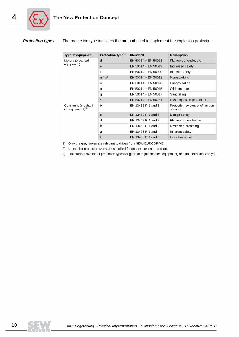
4
10
he New Protection Concept
Protection types The protection type indicates the method used to implement the explosion protection.
Type of equipment Protection type1)
1) Only the gray boxes are relevant to drives from SEW-EURODRIVE.
Standard Description
Motors (electrical equipment)
d EN 50014 + EN 50018 Flameproof enclosure
e EN 50014 + EN 50019 Increased safety
i EN 50014 + EN 50020 Intrinsic safety
n / nA EN 50014 + EN 50021 Non-sparking
m EN 50014 + EN 50028 Encapsulation
o EN 50014 + EN 50015 Oil immersion
q EN 50014 + EN 50017 Sand filling2)
2) No explicit protection types are specified for dust explosion protection.
EN 50014 + EN 50281 Dust explosion protection
Gear units (mechani-cal equipment)3)
3) The standardization of protection types for gear units (mechanical equipment) has not been finalized yet.
b EN 13463 P. 1 and 6 Protection by control of ignition sources
c EN 13463 P. 1 and 5 Design safety
d EN 13463 P. 1 and 3 Flameproof enclosure
fr EN 13463 P. 1 and 2 Restricted breathing
g EN 13463 P. 1 and 4 Inherent safety
k EN 13463 P. 1 and 8 Liquid immersion
T
Drive Engineering - Practical Implementation – Explosion-Proof Drives to EU Directive 94/9/EC
4The New Protection Concept
4.2 Overview of EU Directive 1999/92/EC
In contrast to EU Directive 94/9/EC, which specifies the equipment properties for themanufacturer, the EU Directive 1999/92/EC is directed at system operators. Besidesvarious requirements for the installation and operation of systems, it also defines theclassification of the equipment category to the different danger areas (zones),
System safety EU Directive 1999/92/EC deals with “Minimum regulations to improve protection ofhealth and safety of workers at possible risk through explosive atmospheres.”
The system operator is required to:
• guarantee the safety of the system during the operating time,
• either prevent the formation of explosive mixtures in the system
• or prevent the ignition of explosive mixtures and
• at worst, reduce the harmful effects of an explosion to the extent that health and safe-ty of workers is guaranteed.
• create an explosion protection document and keep it current:
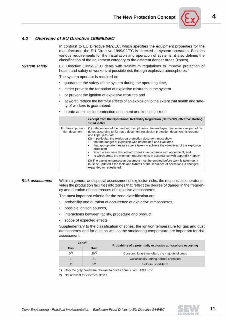
Risk assessment Within a general and special assessment of explosion risks, the responsible operator di-vides the production facilities into zones that reflect the degree of danger in the frequen-cy and duration of occurrences of explosive atmospheres.
The most important criteria for the zone classification are:
• probability and duration of occurrence of explosive atmospheres,
• possible ignition sources,
• interactions between facility, procedure and product
• scope of expected effects
Supplementary to the classification of zones, the ignition temperature for gas and dustatmospheres and for dust as well as the smoldering temperature are important for riskassessment.
excerpt from the Operational Reliability Regulation (BetrSichV, effective starting 10-03-2002)
Explosion protec-tion document
(1) Independent of the number of employees, the employer must ensure as part of his duties according to §3 that a document (explosion protection document) is created and kept up-to-date.(2) In particular, the explosion protection document must show• that the danger of explosion was determined and evaluated• that appropriate measures were taken to achieve the objectives of the explosion
protection• which areas were divided into zones in accordance with appendix 3, and• to which areas the minimum requirements in accordance with appendix 4 apply
(3) The explosion protection document must be created before work is taken up. It must be updated if the tools and fixtures or the sequence of operations is changed, expanded or redesigned.
Zone1)
1) Only the gray boxes are relevant to drives from SEW-EURODRIVE.
Probability of a potentially explosive atmosphere occurringGas Dust
02)
2) Not relevant for electrical drives
202) Constant, long-time, often, the majority of times
1 21 Occasionally, during normal operation
2 22 Seldom, short-term
Drive Engineering - Practical Implementation – Explosion-Proof Drives to EU Directive 94/9/EC
11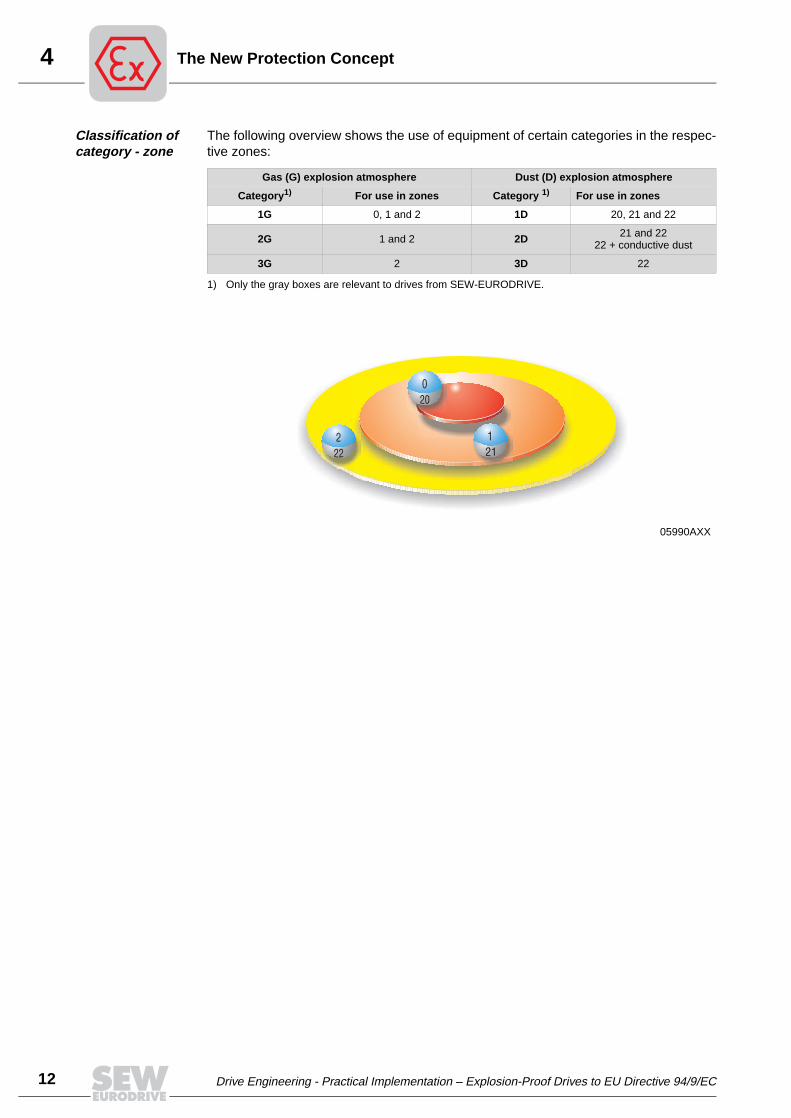
4
12
he New Protection Concept
Classification of category - zone
The following overview shows the use of equipment of certain categories in the respec-tive zones:
Gas (G) explosion atmosphere Dust (D) explosion atmosphere
Category1)
1) Only the gray boxes are relevant to drives from SEW-EURODRIVE.
For use in zones Category 1) For use in zones
1G 0, 1 and 2 1D 20, 21 and 22
2G 1 and 2 2D 21 and 2222 + conductive dust
3G 2 3D 22
05990AXX
T
Drive Engineering - Practical Implementation – Explosion-Proof Drives to EU Directive 94/9/EC

5Drives to EU Directive 94/9/EC
5 Drives to EU Directive 94/9/ECFor explosion-proof equipment, the EU directive 94/9/EC defines
• which equipment falls under the directive
• the requirements for the equipment and its assignment to categories
• the certification of equipment and manufacturing site
• the responsibility of the manufacturer or the person putting it into circulation
5.1 Conformity evaluation
To assess the conformity, the manufacturer must first decide to which group and cate-gory his products belong.
This volume deals exclusively with equipment of Group II for the use in areas that do notbelong to underground mining. As a further limitation, only categories 2 and 3 that arecustomary for drives are taken into account.
5.2 EC-type examination
Electrical equip-ment
Electrical equipment of category 2 which also includes motors, motors with frequencyinverters and sensors of drive engineering must pass through an EC-type examinationat a notified body. If the submitted type meets the provisions of the Directive, the notifiedbody issues an EC-type-examination certificate. The certificate contains the name andaddress of the manufacturer, conclusions of the examination and the necessary dataffor identification of the approved type. A list of the relevant parts of the technical docu-mentation shall be annexed to the certificate and a copy kept by the notified body.
Each notified body shall communicate to the other notified bodies the relevant informa-tion concerning the EC-type-examination certificate.
The manufacturer shall keep copies of EC-type examination certificates and their addi-tions for a period ending at least 10 years after the last equipment was manufactured.
Category Type Conformity through
2Electrical units
EG prototype test and• Conformity based on type of construction or• Production quality assurance
Non-electrical units Technical documentation to designated authority and internal pro-duction control
3 All Internal production control
Drive Engineering - Practical Implementation – Explosion-Proof Drives to EU Directive 94/9/EC
13
5
14
rives to EU Directive 94/9/EC
5.3 Production quality assurance
In addition to the EC-type-examination certificate, a requirement for the approval of ex-plosion-proof electrical equipment of category 2 is that the production quality assuranceis certified by a notified body und monitored permanently.
5.4 Internal control of production
Mechanical equipment
Mechanical equipment of category 2 and all equipment of category 3 are subject to in-ternal production control. This means that the manufacturer shall establish a designatedselection of documentation to cover the design, manufacture and operation of the prod-uct and keep it for a period ending at least 10 years after the last piece of equipment wasmanufactured. The manufacturer shall take all measures necessary to ensure that themanufacturing process guarantees compliance of the manufacture equipment with thetechnical documentation referred to above.
5.5 Declaration of conformity and CE marking
In all cases, the manufacturer draws up a declaration of conformity that certifies the con-formity of the equipment with the corresponding standards and regulations.
The equipment receives a CE marking to provide an external indicator of the conformitywith European directives. The marking indicates not only conformity with 94/9/EC, butalso conformity to all concurrently applicable directives, such as Directive 89/336/EEC(Electromagnetic Compatibility).
The low-voltage directive does not apply to equip-ment according to 94/9/EC
The Low-Voltage Directive 73/23/EEC, on the other hand, explicitly does not apply toequipment that is subject to the EU Directive 94/9/EC.
However, all electrical equipment operated with explosion-proof equipment outside thepotentially explosive atmosphere, is subject to the low-voltage directive. The same ap-plies to protection, control and monitoring equipment installed in switch cabinets and, ofcourse, to separate frequency inverters for speed control of motors.
D
Drive Engineering - Practical Implementation – Explosion-Proof Drives to EU Directive 94/9/EC

5Drives to EU Directive 94/9/EC
5.6 Designation key for explosion-proof equipment
All explosion-proof electrical equipment continues to be designated with a uniform key.The complete designation became longer due to the addition of equipment group, cate-gory, distinguishing feature for gas or dust, and the listing of the designated authorityresponsible for certification.
For example, an explosion-proof AC motor designated for use in zone 1 with protectiontype “Increased Safety” now carries the following identification next to the type designa-tion:
EEx e II T3
According to EU Directive 94/9/EC, the new designation is:
0102 II 2G EEx e II T3
Drive Engineering - Practical Implementation – Explosion-Proof Drives to EU Directive 94/9/EC
15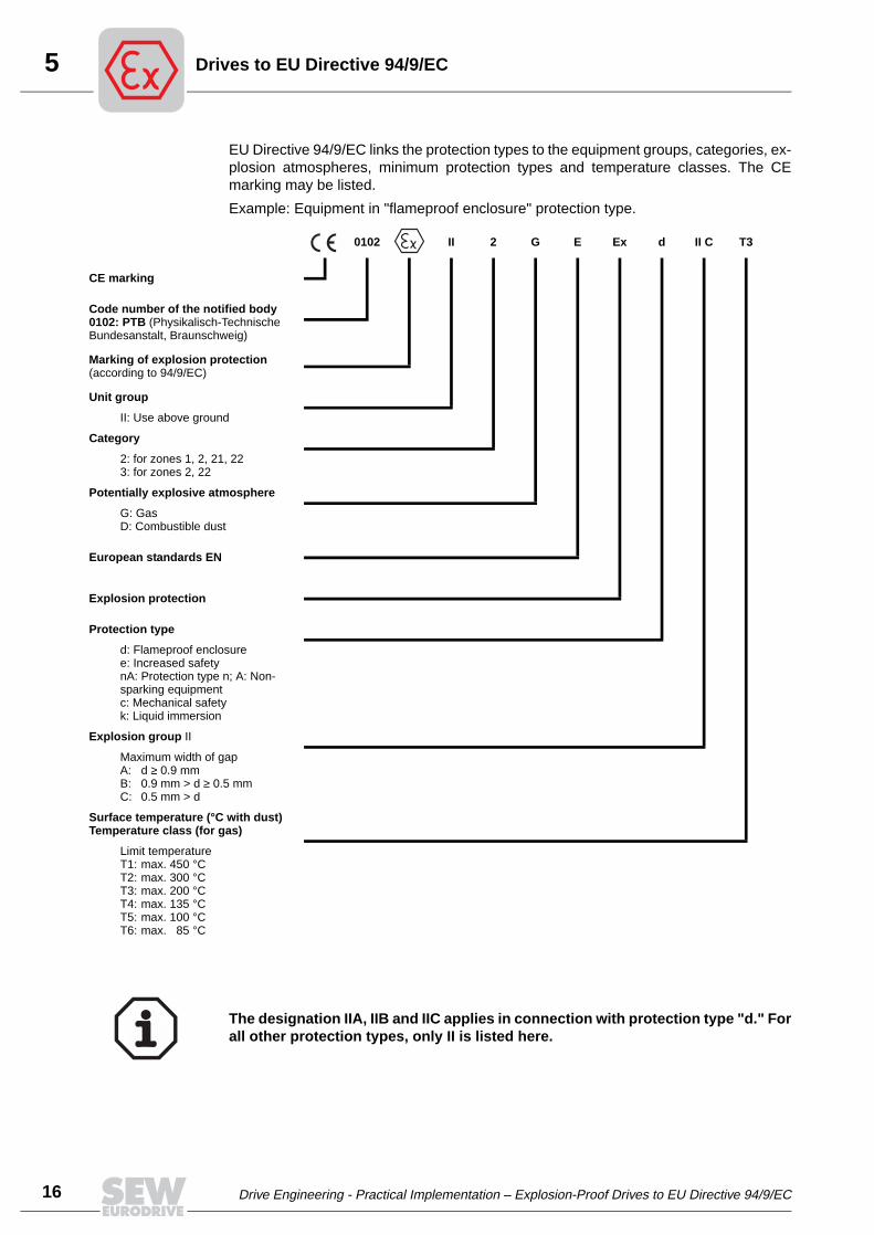
5
16
rives to EU Directive 94/9/EC
EU Directive 94/9/EC links the protection types to the equipment groups, categories, ex-plosion atmospheres, minimum protection types and temperature classes. The CEmarking may be listed.
Example: Equipment in "flameproof enclosure" protection type.
0102 II 2 G E Ex d II C T3
CE marking
Code number of the notified body0102: PTB (Physikalisch-Technische Bundesanstalt, Braunschweig)
Marking of explosion protection (according to 94/9/EC)
Unit group
II: Use above ground
Category
2: for zones 1, 2, 21, 223: for zones 2, 22
Potentially explosive atmosphere
G: GasD: Combustible dust
European standards EN
Explosion protection
Protection type
d: Flameproof enclosuree: Increased safetynA: Protection type n; A: Non-sparking equipmentc: Mechanical safetyk: Liquid immersion
Explosion group II
Maximum width of gapA: d ≥ 0.9 mmB: 0.9 mm > d ≥ 0.5 mmC: 0.5 mm > d
Surface temperature (°C with dust)Temperature class (for gas)
Limit temperatureT1: max. 450 °CT2: max. 300 °CT3: max. 200 °CT4: max. 135 °CT5: max. 100 °CT6: max. 85 °C
The designation IIA, IIB and IIC applies in connection with protection type "d." Forall other protection types, only II is listed here.
D
Drive Engineering - Practical Implementation – Explosion-Proof Drives to EU Directive 94/9/EC

5Drives to EU Directive 94/9/EC
5.7 Mechanical equipment according to EU Directive 94/9/EC
In contrast to electrical equipment, mechanical equipment exhibits important differencesfor use in potentially explosive atmospheres.
In contrast to electrical equipment, the gas and dust explosion protection is cov-ered by the same standard series.
Responsibility of the manufacturer
After the standard series EN 13463 is available in the future, every manufacturer will beable to declare the mechanical equipment for use as equipment category 2 or 3 in directresponsibility as explosion-proof equipment for gas and dust atmospheres. In this con-text it is also important that the manufacturer approves the equipment of category 2 indirect responsibility for use in zones 1 or 21. For electrical equipment, an EC-type ex-amination is required.
New protection types
The same standard also defines new protection types. In the future, different protectiontypes for mechanical equipment will be applicable.
Category 3 To be able to designate gear units as equipment of category 3, the manufacturer mustdemonstrate fulfillment of EN 13463-1 “Basic Methodology and Requirements.” Thedesignation for this category does not contain any protection type.
Category 2 If gear units must now be designated as equipment of category 2, two sections of thestandard series EN 13463 must be met. It is left to the manufacturer to decide which part( 2 8 ) will be met in addition to Part 1. The protection type is defined depending uponthe selected part. Of highest importance for gear unit engineering are the standardsEN13463-5 and EN13463-8. EN13463-5 is entitled “Protection by constructional safety”and corresponds to protection type “c.” EN13463-8 is entitled “Liquid immersion” andcorresponds to protection type “k.”
Since the standards series EN 13463 is still under development, no detailed informationconcerning the contents of protection types or the characteristic properties of these pro-tection types can be given here.
Protection type Description Application
“c“Constructonal safety
according to EN13463-5
An explosion protection type which uses structural measures to ensure protection against possible igni-tion through moving components, generated hot sur-faces, sparks and adiabatic compressions.
For all non-electrical equipment of category 2G and 2D, provided that they do not have any ignition sources that can be created through antici-pated faults.
“k“Liquid immersion
according to EN13463-8
A protection type in which potential ignition sources cannot become active or are separated from the ignit-able atmosphere, either through complete immersion in a protective liquid or through partial immersion and continuous wetting of its active surface with a protec-tive liquid, so that a potentially explosive atmosphere that can be located above the liquid or outside the equipment housing cannot be ignited.
For all non-electrical equipment of categories 2G, 2D, 3G and 3D.
ok!
The explosion-proof gear units from SEW-EURODRIVE are always designed for appli-cations in categories II2G/II2D. They automatically meet the requirements of categoriesII3G/II3D, which means explosion-proof gear units of categories II2G/II2D can also beused in applications for categories II3G/II3D.
Drive Engineering - Practical Implementation – Explosion-Proof Drives to EU Directive 94/9/EC
17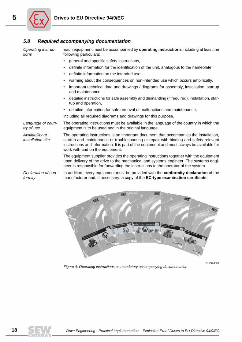
5
18
rives to EU Directive 94/9/EC
5.8 Required accompanying documentation
Operating instruc-tions
Each equipment must be accompanied by operating instructions including at least thefollowing particulars:
• general and specific safety instructions,
• definite information for the identification of the unit, analogous to the nameplate,
• definite information on the intended use,
• warning about the consequences on non-intended use which occurs empirically,
• important technical data and drawings / diagrams for assembly, installation, startupand maintenance
• detailed instructions for safe assembly and dismantling (if required), installation, star-tup and operation,
• detailed information for safe removal of malfunctions and maintenance,
including all required diagrams and drawings for this purpose.
Language of coun-try of use
The operating instructions must be available in the language of the country in which theequipment is to be used and in the original language.
Availability at installation site
The operating instructions is an important document that accompanies the installation,startup and maintenance or troubleshooting or repair with binding and safety-relevantinstructions and information. It is part of the equipment and must always be available forwork with and on the equipment.
The equipment supplier provides the operating instructions together with the equipmentupon delivery of the drive to the mechanical and systems engineer. The systems engi-neer is responsible for forwarding the instructions to the operator of the system.
Declaration of con-formity
In addition, every equipment must be provided with the conformity declaration of themanufacturer and, if necessary, a copy of the EC-type examination certificate.
51294AXXFigure 4: Operating instructions as mandatory accompanying documentation
Explosionsgeschützte Verstellgetriebe
VARIMOT ® und Zubehör
Ausgabe09/2000
Betriebsanleitung1050 6802 / DE
Explosionsgeschützte Verstellgetriebe
VARIBLOC® und Zubehör Ausgabe
09/2000
Betriebsanleitung1050 6004 / DE
04/2000Explosionsgeschützte Getriebe
Typenreihen R..7, F..7, K..7, S..7, Spiroplan® W
Ausgabe
11/2002
Betriebsanleitung1055 520x / DE
Explosionsgeschützte Drehstrommotoren,
Drehstrombremsmotoren
Ausgabe
03/2002
Betriebsanleitung
1053 3605 / DE
MOVI-SWITCHÆ in Kategorie 3D
(Staub-Explosionsschutz)
Ausgabe
07/2000
Betriebsanleitung
10504400 / DE
D
Drive Engineering - Practical Implementation – Explosion-Proof Drives to EU Directive 94/9/EC

6Gas Explosion Protection
6 Gas Explosion Protection6.1 Categorization
The EU Directive 94/9/EC adopts essentially the existing statutes for electrical equip-ment and supplements them by the classification into categories.
Ignition tempera-ture
After determining the danger level and subsequently the zone through the systems op-erator, the systems operator determines the ignition temperature for the possible gasmixture.
Temperature class / explosion group
The temperature class T.. is derived from the ignition temperature. Yet another char-acteristic of the gas-air-mixture is the explosion group, i.e., the ability for transmissionof internal ignition (relevant for protection type d). Here, the dangerous nature increasesfrom explosion group IIA to IIC. Gases of explosion group IIC are the most dangerousones.
Gases and vapors Ignition tem-perature °C1)
Temperature class1) Explosion group1)
T1 [°C] T2 [°C] T3 [°C] T4 [°C] T5 [°C] T6 [°C]IIA IIB IIC
> 450 300 ... 450 200 ... 300 135 ... 200 100 ... 135 85 ... 100
Ethanal 140
Acetone 540
Acetylene 305
Ammonia 630
Benzine 220 - 300
Benzene (pure) 555
Cyclohexanone 430
Diesel fuels 220 - 300
Ethanoic acid 485
Acetic anhydride 330
Ethane 515
Ethyl acetate 460
Ethyl alcohol 425
Ethyl chloride 510
Ethylene 425
Ethyl ether 170
Ethyl glycol 235
Heating oils 220 - 300
Carbon oxide 605
Methane 595
Methanol 455
Methyl chloride 625
Naphthalene 540
n-butane 365
n-butyl alcohol 340
n-hexane 240
Phenol 595
Propane 470
Carbon bisulphide 95
Hydrogen sulphide 270
City gas 560
Toluol 535
Hydrogen 560
1) No responsibility is accepted for the accuracy of this information; please verify in particular cases at appropriate authority!
Drive Engineering - Practical Implementation – Explosion-Proof Drives to EU Directive 94/9/EC
19
6
20
as Explosion Protection
Unit category The next step consists of determining the equipment category. Essential criteria forthis purpose include:
• the zone
• conditions at the site that could make a uniform equipment outfit necessary
6.2 Protection types
In the case of several possibilities, the specification of the protection type is influencedby the following aspects:
• the costs
• typical country-specific practices
• conditions at the site that could make a uniform equipment outfit necessary
• the operating mode
51291AXXFigure 5: Motor with protection type "Increased Safety," II2GEExe design
G
Drive Engineering - Practical Implementation – Explosion-Proof Drives to EU Directive 94/9/EC

6Gas Explosion Protection
Protection type Description Application
“d”Flameproof enclosure in accordance with EN
50018
Potential ignition sources are enclosed in a flameproof housing in such a way that the explosive gas mixture may enter and possibly ignite, but the mixture burnt inside is forced to cool off on its way to the outside by means of “ignition gaps.” The temperature which is now lower and not dangerous prevents an ignition of the external atmosphere. The gas-air-mixtures are classified into explosion groups depending upon their ignitability and explosive force. The construction of flameproof housings is dependent upon the “maximum experimental safe gap” of the ignition gap. In principle, the designation of the flameproof equipment includes the explosion group.
Within the scope of electrical drive engineering primarily for equipment where its operation may create sparks: collector, commutator, and slip ring units, mechanical brakes. Also used for squirrel-cage motors if very high danger potentials are present, if the chopping operation changes the motor from thermally crit-ical stator to thermally critical rotor that can no longer be protected via PTC thermistor, or if electronic speed control is required for application in zone 1.
“e”Increased safety in accordance with EN
50019
To reduce the risk of sparking during operation, special construction measures are taken, such as:• maintaining minimum safe gaps,• observing creepage clearances and distances,• special selection of enameled wires,• careful selection of utilized plastics and insulating
materials.
To prevent excessive surface temperatures, the criti-cal components are taken into consideration in the electrical specification. The verification of maintaining permitted surface temperatures must be carried out through complicated measurements. An error must be observed in the specification of the equipment and the subsequent test. The sum of these measures practically rules out the ignition of air-gas-mixtures.Special monitoring of potential ignition sources with motor protection switch or PTC thermistors ensures that a temperature rise to ignitable temperatures does not occur. With a stalling of the motor at operating temperature condition, the motor protection switch must switch off the motor at the specified Ia/In within the tE time.If PTC thermistors (TF) are used as the only moni-toring device, a tA time is determined and specified. With a stalling of the rotor, the TF must trip in cold con-dition within this time period.
This protection type is applicable only for equipment for which sparking is typically not expected. Within the scope of electrical drive engineering, protection type “e” in the power range up to approx. 50 kW is applied prima-rily for continuous duty squirrel-cage motors in zone 1 with fixed supply voltage and frequency. In exceptional cases (single certification), electroni-cally speed-controlled squirrel-cage motors can also be designed as “e.” Single certifications for operating modes S2, S3 and S4 are also possi-ble up to certain limits. In addition, “e” is frequently used in combinations such as with “d:” e.g., explosion-proof motors with terminal box in “e.”
Drive Engineering - Practical Implementation – Explosion-Proof Drives to EU Directive 94/9/EC
21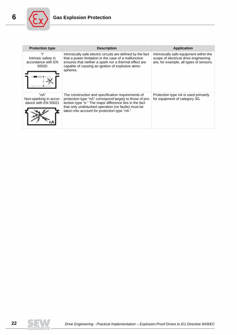
6
22
as Explosion Protection
Protection type Description Application
“i“Intrinsic safety in
accordance with EN 50020
Intrinsically safe electric circuits are defined by the fact that a power limitation in the case of a malfunction ensures that neither a spark nor a thermal effect are capable of causing an ignition of explosive atmo-spheres.
Intrinsically safe equipment within the scope of electrical drive engineering are, for example, all types of sensors.
“nA”Non-sparking in accor-dance with EN 50021
The construction and specification requirements of protection type “nA” correspond largely to those of pro-tection type “e.” The major difference lies in the fact that only undisturbed operation (no faults) must be taken into account for protection type “nA.”
Protection type nA is used primarily for equipment of category 3G.
nA
G
Drive Engineering - Practical Implementation – Explosion-Proof Drives to EU Directive 94/9/EC

6Gas Explosion Protection
6.3 Protection type “e” standard for AC motors in zone 1
The protection type “e” was developed in Germany several decades ago and has provenitself in practical applications. This protection type made its way into international stan-dards by means of IEC 60079-7 and was subsequently accepted into the series of har-monized European standards as EN 50019.
"e": extremely economical
In contrast to protection type “d,” “increased safety” is a very economical and space- andtime-saving protection type that is now widely used in Europe.
The use of protection type “e” in zone 1 for squirrel-cage motors in the range up to ap-proximately 50 kW is now given priority in Europe. In Germany, 75 to 80% of the motorsin zone 1 are protected in accordance with “e.”
Principle The principle of protection type “e” lies in avoiding ignition sources. The operating prin-ciple of the asynchronous motor does not allow any sparking during operation. Con-structive measures ensure that any possible risk factors due to breakdowns and equip-ment failures are reduced to a minimum.
Continuous duty For all motors that are used primarily as continuous duty, the remaining main risk,overload and therefore increased surface temperature, is controlled by proven monitors.
Sole protection through motor protection switch
Motor protection switches approved by a notifed body must be set to the rated currentof the motor. The tripping time of the protection switch can be determined by means ofthe characteristic curve of the protection switch and the starting current ratio IA/IN of themotor. It must be shorter than the tE time of the motor.
Sole protection through PTC ther-mistor
PTC thermistors are built into the motor winding. They are connected to an approvedPTC thermistor trip switch. If the motor, starting in cold condition, is connected to thepower supply system in stalled condition, the time tA passes until the PTC thermistor tripswitch responds. As a prerequisite, the motor must be a stator-critical motor, i.e., thehighest temperature increase occurs in the stator. Here, the starting current ratio IA/INhas the same significance as with a motor protected by a motor protection switch.
Protection through motor protection switch and PTC ther-mistor
The safety is increased significantly. Only the monitoring principle with motor protectionswitch is certified.
Drive Engineering - Practical Implementation – Explosion-Proof Drives to EU Directive 94/9/EC
23
6
24
as Explosion Protection
Type examina-tion certificate
The demonstrated properties of the motors under specified voltage and frequency con-ditions within the scope of the EC-type examination in connection with the monitoringsystem are recorded on the examination certificate of the notified body.
Limitations for "e" With the exception of complicated single certifications, protection type “e” is not pos-sible in the following cases:
• AC squirrel-cage motors for intermittent operation, switching operation, short-termoperation and others that cannot be reliably protected against overload,
• electrical machines with sliprings, commutators, and collectors (sparking),
• operation with frequency inverter.
In these cases, the usual protection type is flameproof enclosure "d".
The following diagram shows the sample temperature variation on a motor with blockedshaft. Due to the fault, the motor heats up rapidly and can reach critical temperatureswithin a short period of time. The temperature climbs from the rated temperature ϑN dur-ing the heating period tE to the maximum permitted surface temperature T3 = 200° C.
To effectively protect the motor against inadmissibly high temperatures, the disconnec-tion of the motor from the power supply system must be carried out in a time that is short-er than the heating time tE.
51015AXX
ϑW = Maximum permitted winding temperatureϑN = Steady-state temperature of the motor in operation without malfunctionsϑamb = Ambient temperature
200
175
150
125
100
75
50
25
0
ϑ [°C]
ϑamb
ϑN
ϑW
tE
t
T3
G
Drive Engineering - Practical Implementation – Explosion-Proof Drives to EU Directive 94/9/EC

6Gas Explosion Protection
For this purpose, special motor protection switches with a trip characteristic accordingto EN50019 were used (→ following chart).
In practice, this means for motors with protection type "e" that the heating time tE de-pendent upon the ratio of starting current to rated current (IA/IN) must fall above the tripcharacteristic (M). The switch-off time of the motor protection switch must fall belowthe trip characteristic (S).
Example Drive in accordance with II 2G EEx e II T3: eDT80N4 / tE = 22 s / IA/IN = 4.4
51016AXX
S = Range of protection deviceM = Range of motors
5
10
20
40
60
120
1 1.5 2 43 5 6 7 8 9 10
EN 50019
tE
[s]
IA/IN
M
S
Drive Engineering - Practical Implementation – Explosion-Proof Drives to EU Directive 94/9/EC
25
6
26
as Explosion Protection
6.4 Special features of speed-controlled AC motors
With the exception of mechanical variable speed gear units, today’s squirrel-cage mo-tors in connection with frequency inverters are typically speed-controlled.
The explosion protection of such drives must be solved differently than that for equip-ment linked directly to the power supply system because
• voltage and frequency are variable,
• the variable speed also influences the thermal development due to the different cool-ing effect of the fans.
A distinction is made between explosion-proof motors with inverters outside of the dan-ger zones and motors with integrated frequency inverters.
Use of category 2G in zone 1
The inverter-supplied drives listed first of category 2G for zone 1 can be designed asprotection type “d” or “e.”
The design in “e” is complicated, generally too expensive for individual drives, and dueto the mandatory conformity declaration of every combination of inverter, motor, andmonitoring system with the intended function often also unacceptable with respect to thedelivery time.
However, the flameproof motor can be tested as type independent of the individual in-verter make, taking into account the maximum speed setting range for the inverter op-eration.
Thermal monitoring of the flameproof motor is carried out through PTC thermistors assole protection. The inverter current must be limited to a maximum value of 2 x IN. Thefrequency may not exceed 110% of the tested frequency.
Explosion-proof inverter motors for zone 1 are delivered exclusively in flameproof enclo-sure.
Use of category 3 in zone 2 or 22
Speed-controlled applications in zone 2 and 22 are designed preferentially with ACsquirrel-cage motors of category 3 and frequency inverters approved according to tech-nical specifications in the switch cabinet outside the potentially explosive zone. This re-quires that the motor is operated with limited torque. The thermal monitoring is carriedout exclusively with PTC thermistors and approved tripping unit.
G
Drive Engineering - Practical Implementation – Explosion-Proof Drives to EU Directive 94/9/EC

6Gas Explosion Protection
MOVIMOT® inverter motors of category 3D are also recommended for operation in zone22.
51283AXXFigure 6: Geared motor with integrated MOVIMOT® frequency inverter in II3D design
Drive Engineering - Practical Implementation – Explosion-Proof Drives to EU Directive 94/9/EC
27
7
28
ust Explosion Protection
7 Dust Explosion ProtectionToday, the dust explosion protection receives a more appropriate significance with thenew zone classification according to EU directive 1999/92/EC. Dust explosions occurmore frequently than expected. Here, dusts from food and feed are prominent.
Until now, the dust explosion protection was regulated imperfectly. A majority of theelectrical equipment used in zone 11 was not certified until now.
51284AXXFigure 7: Brake motor in II3D design (dust explosion protection)
D
Drive Engineering - Practical Implementation – Explosion-Proof Drives to EU Directive 94/9/EC
7Dust Explosion Protection
Difference com-pared to gas
In contrast to explosion protection with gas atmospheres, the following must be ob-served for dust:
• dust does not evaporate but deposits itself in an increasingly thicker layer
• the dust explosion protection is highly dependent upon the operating conditions.
An ignitable gas atmosphere can be diluted through strong venting to the point that nodanger of explosion exists any longer. If the same procedure is used for dust accumu-lations, they are whirled up, distributed and form additional sources of danger. The dustlayers obstruct the cooling of the equipment and, thereby form an additional ignition risk.This means that periodic cleaning of the respective equipment is absolutely mandatoryfor the dust explosion protection.
For this reason, three characteristic values are used for the atmosphere of ignitabledusts:
• Ignition temperature
• Smoldering temperature
• Maximum surfacetemperature
7.1 Characteristic values for dust explosion protection in accordance with EN50281-1-1:1998
Smoldering tem-perature
The lowest temperature of a hot surface at which a deposited layer of flammable dustwith a thickness of 5 mm barely ignites is referred to as smoldering temperature T5
mm.
Ignition tempera-ture
The lowest temperature at which a dust cloud (dust-air-mixture) with flammable dust ofa particle size between approx. 0.02 and 0.4 mm and a concentration between 20 g/m3
and 2 kg/m3 barely ignites is referred to as ignition temperature TCI.
Maximum surface temperature
The maximum surface temperature that a unit reaches during rated operation and mal-functioning operation is referred to as maximum surface temperature Tmax and is partof the equipment designation.
Reference temper-ature
Unless otherwise indicated, this temperature information refers to a maximum ambienttemperature of 40° C.
Drive Engineering - Practical Implementation – Explosion-Proof Drives to EU Directive 94/9/EC
29
7
30
ust Explosion Protection
Interaction The possible change between whirled-up and deposited dust is treacherous: the in-creased dust concentration in the dust cloud tends to reduce the danger of explosion,the larger thickness of the deposited layer increases it.
For this reason, a sufficient safety range must be maintained between the permitted sur-face temperature of the equipment and the ignition and smoldering temperature of thedust.
Interrelationships between the maximum surface temperature and the smoldering or ig-nition temperature:
• Tmax = T5 mm - 75 K
• Tmax = 2/3 × TCI
For the specification of the maximum permitted surface temperature of the equipment,the smaller of the two values Tmax must be taken into account.
Example A grain silo is to be equipped with drives. The values for Tmax from the table "Tempera-ture characteristic of selected dust types" amount to 215° C from the smoldering tem-perature table and 280° C from the ignition temperature table. The maximum permittedsurface temperature may not exceed 215° C.
If dust deposits above 5 mm can be expected, the maximum permitted surface temper-ature of the equipment must be reduced accordingly. The following group of curves fur-nishes reference values:
50267AXXFigure 8: Smoldering temperature in reference to layer thickness
400
400°C � T5mm
320°C � T5mm � 400°C
250°C � T5mm � 320°C
300
200
100
00 10 20 30 40
a [mm]50
Tmax [°C]
T5mm
D
Drive Engineering - Practical Implementation – Explosion-Proof Drives to EU Directive 94/9/EC
7Dust Explosion Protection
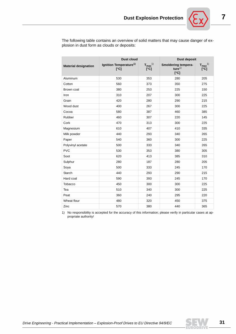
The following table contains an overview of solid matters that may cause danger of ex-plosion in dust form as clouds or deposits:
Material designation
Dust cloud Dust deposit
Ignition Temperature1)
[°C]
1) No responsibility is accepted for the accuracy of this information; please verify in particular cases at ap-propriate authority!
Tmax1)
[°C]Smoldering tempera-
ture1)
[°C]
Tmax1)
[°C]
Aluminum 530 353 280 205
Cotton 560 373 350 275
Brown coal 380 253 225 150
Iron 310 207 300 225
Grain 420 280 290 215
Wood dust 400 267 300 225
Cocoa 580 387 460 385
Rubber 460 307 220 145
Cork 470 313 300 225
Magnesium 610 407 410 335
Milk powder 440 293 340 265
Paper 540 360 300 225
Polyvinyl acetate 500 333 340 265
PVC 530 353 380 305
Soot 620 413 385 310
Sulphur 280 187 280 205
Soya 500 333 245 170
Starch 440 293 290 215
Hard coal 590 393 245 170
Tobacco 450 300 300 225
Tea 510 340 300 225
Peat 360 240 295 220
Wheat flour 480 320 450 375
Zinc 570 380 440 365
Drive Engineering - Practical Implementation – Explosion-Proof Drives to EU Directive 94/9/EC
31
7
32
ust Explosion Protection
7.2 New zone classification according to EC Directive 1999/92/EC
The introduction of Directive 1999/92/EC results in fundamental changes for the atmo-sphere of flammable dust.
The adoption of the IEC classification of potentially explosive atmospheres with ignitabledust-air-mixtures in 3 zones is new (Figure 9):
• Zone 20 (zone 10 until now),
• Zone 21 (zone 10 or 11 until now), and
• Zone 22 (zone 11 until now).
Comparison: "old" and "new" zones
It must be observed here that areas of the “old” zones 10 and 11 do not automaticallychange over to zones 20, 21 or 22. The zone classification must be verified in accor-dance with the new requirements. This situation will intensify after 1 July 2003 (end oftransitional period), because only equipment approved for the new zone classificationmay be sold as of that date.
For this reason, system operators should inform themselves early about the new zoneclassification.
Help It is highly recommended that the system operator consult the proper monitoring author-ity (e.g. UL) or employer’s liability insurance association if any uncertainties exist.
05992AENFigure 9: Change in zone classification
D
Drive Engineering - Practical Implementation – Explosion-Proof Drives to EU Directive 94/9/EC
7Dust Explosion Protection
7.3 Standards / design regulations for dust explosion protection
The requirements of EU Directive 1999/92/EC for electrical equipment were implement-ed with the introduction of EN60079-14 (installation regulations) and EN50281-1-2(equipment regulations).
In contrast to gas explosion protection for electrical equipment with several protectiontypes, there are no different protection types for gas explosion protection.
IP enclosures One of the decisive design criteria for equipment used in potentially explosive dust at-mospheres is the fulfillment of certain IP enclosures (protection from foreign matter en-tering the equipment in accordance with EN 60529).
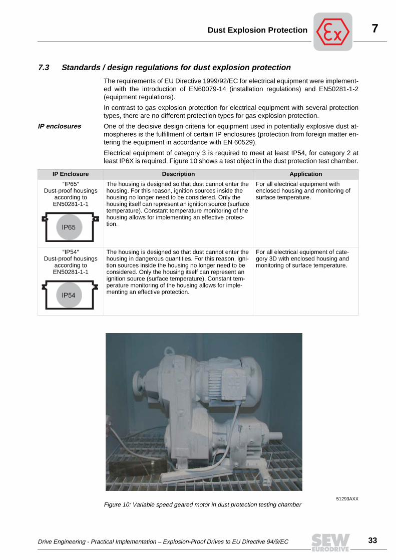
Electrical equipment of category 3 is required to meet at least IP54, for category 2 atleast IP6X is required. Figure 10 shows a test object in the dust protection test chamber.
IP Enclosure Description Application
“IP65“Dust-proof housings
according to EN50281-1-1
The housing is designed so that dust cannot enter the housing. For this reason, ignition sources inside the housing no longer need to be considered. Only the housing itself can represent an ignition source (surface temperature). Constant temperature monitoring of the housing allows for implementing an effective protec-tion.
For all electrical equipment with enclosed housing and monitoring of surface temperature.
“IP54“Dust-proof housings
according to EN50281-1-1
The housing is designed so that dust cannot enter the housing in dangerous quantities. For this reason, igni-tion sources inside the housing no longer need to be considered. Only the housing itself can represent an ignition source (surface temperature). Constant tem-perature monitoring of the housing allows for imple-menting an effective protection.
For all electrical equipment of cate-gory 3D with enclosed housing and monitoring of surface temperature.
IP65
IP54
51293AXXFigure 10: Variable speed geared motor in dust protection testing chamber
Drive Engineering - Practical Implementation – Explosion-Proof Drives to EU Directive 94/9/EC
33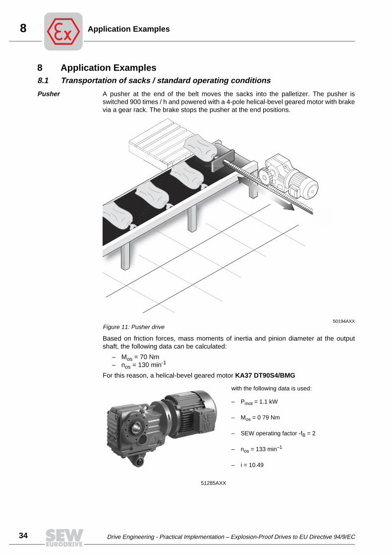
8
34
pplication Examples
8 Application Examples8.1 Transportation of sacks / standard operating conditions
Pusher A pusher at the end of the belt moves the sacks into the palletizer. The pusher isswitched 900 times / h and powered with a 4-pole helical-bevel geared motor with brakevia a gear rack. The brake stops the pusher at the end positions.
Based on friction forces, mass moments of inertia and pinion diameter at the outputshaft, the following data can be calculated:
– Mos = 70 Nm– nos = 130 min-1
For this reason, a helical-bevel geared motor KA37 DT90S4/BMG
50194AXXFigure 11: Pusher drive
with the following data is used:
– Pmot = 1.1 kW
– Mos = 0 79 Nm
– SEW operating factor -fB = 2
– nos = 133 min–1
– i = 10.49
51285AXX
A
Drive Engineering - Practical Implementation – Explosion-Proof Drives to EU Directive 94/9/EC
8Application Examples
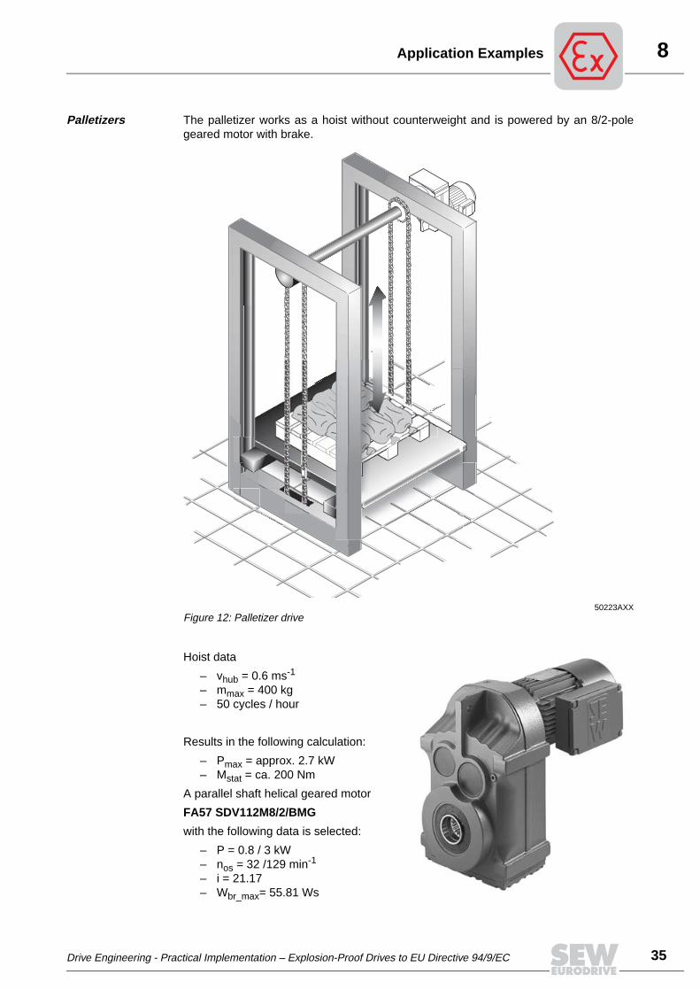
Palletizers The palletizer works as a hoist without counterweight and is powered by an 8/2-polegeared motor with brake.
Hoist data
– vhub = 0.6 ms-1
– mmax = 400 kg– 50 cycles / hour
Results in the following calculation:
– Pmax = approx. 2.7 kW– Mstat = ca. 200 Nm
A parallel shaft helical geared motor
FA57 SDV112M8/2/BMG
with the following data is selected:
– P = 0.8 / 3 kW– nos = 32 /129 min-1
– i = 21.17– Wbr_max= 55.81 Ws
50223AXXFigure 12: Palletizer drive
Drive Engineering - Practical Implementation – Explosion-Proof Drives to EU Directive 94/9/EC
35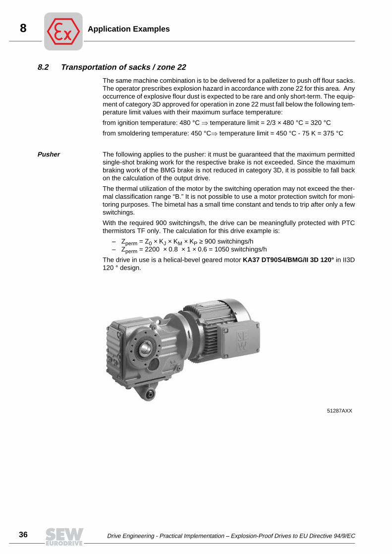
8
36
pplication Examples
8.2 Transportation of sacks / zone 22
The same machine combination is to be delivered for a palletizer to push off flour sacks.The operator prescribes explosion hazard in accordance with zone 22 for this area. Anyoccurrence of explosive flour dust is expected to be rare and only short-term. The equip-ment of category 3D approved for operation in zone 22 must fall below the following tem-perature limit values with their maximum surface temperature:
from ignition temperature: 480 °C ⇒ temperature limit = 2/3 × 480 °C = 320 °C
from smoldering temperature: 450 °C⇒ temperature limit = 450 °C - 75 K = 375 °C
Pusher The following applies to the pusher: it must be guaranteed that the maximum permittedsingle-shot braking work for the respective brake is not exceeded. Since the maximumbraking work of the BMG brake is not reduced in category 3D, it is possible to fall backon the calculation of the output drive.
The thermal utilization of the motor by the switching operation may not exceed the ther-mal classification range “B.” It is not possible to use a motor protection switch for moni-toring purposes. The bimetal has a small time constant and tends to trip after only a fewswitchings.
With the required 900 switchings/h, the drive can be meaningfully protected with PTCthermistors TF only. The calculation for this drive example is:
– Zperm = Z0 × KJ × KM × KP ≥ 900 switchings/h– Zperm = 2200 × 0.8 × 1 × 0.6 = 1050 switchings/h
The drive in use is a helical-bevel geared motor KA37 DT90S4/BMG/II 3D 120° in II3D120 ° design.
51287AXX
A
Drive Engineering - Practical Implementation – Explosion-Proof Drives to EU Directive 94/9/EC

8Application Examples
Palletizers Explosion-proof pole-changing drives are limited in their adaptability to changing oper-ating conditions. For this reason, we decided to drive the palletizer with a certified invert-er drive consisting of a 4-pole geared motor and MOVITRAC® 31C frequency inverteralso with respect to future adaptation to other procedures.
The calculation results in a parallel shaft helical geared motor
type FA57 DV112M4/BMG/II3D T120° which is powered by the
MOVITRAC® 31C frequency inverter of type MC31C 030-503-4-00.
51317AXX
Parallel shaft helical geared motor in shaft-mounted version, dust explosion protectiondesign II3D 120° and MOVITRAC® 31C frequency inverter
Drive Engineering - Practical Implementation – Explosion-Proof Drives to EU Directive 94/9/EC
37
8
38
pplication Examples
8.3 Transportation of sacks / zone 1
The operating range is defined as zone 1 for the use in a chemical plant. Explosive gasmay occur occasionally during normal operation.
Pusher A brake motor of II2G Eex ed IIB T3 design is selected for the clocked pusher, typeeDT90S4/BC2/HR/TF with 1.1 kW.
The starting frequency test is identical with that listed under 8.2.:
Zperm = 2200 × 0.8 × 1 × 0.6 = 1050 switchings/h ≥ 900 switchings/h
The designation for the complete geared motor is KA37 eDT90S4/BC2/HR/TF with i =10.49.
In addition, it must be checked whether the single-shot maximum braking work for theBC2 brake is not exceeded. The calculation results in a braking work of 70 Ws. The max-imum braking work of the BC2 brake with approx. 500 Ws for 900 switchings/h is muchhigher.
Palletizers If a frequency inverter is used for exact positioning of the hoist drive of the palletizer, aflameproof brake motor is required that is powered by a MOVITRAC® or MOVIDRIVE®
frequency inverter.
Explosion-proof motors are approved for inverter operation with a certain maximumspeed setting range based on their type examination. Unlike protection type “IncreasedSafety,” they are not tied to certain frequency inverters. Thermal monitoring of the flame-proof motor is carried out through PTC thermistors as sole protection. The inverter cur-rent must be limited to a maximum value of 2 x IN. The frequency may not exceed 110%of the tested frequency.
A
Drive Engineering - Practical Implementation – Explosion-Proof Drives to EU Directive 94/9/EC
9Service and Maintenance
9 Service and Maintenance
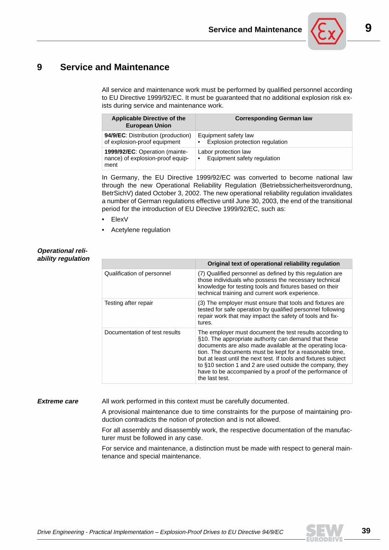
All service and maintenance work must be performed by qualified personnel accordingto EU Directive 1999/92/EC. It must be guaranteed that no additional explosion risk ex-ists during service and maintenance work.
In Germany, the EU Directive 1999/92/EC was converted to become national lawthrough the new Operational Reliability Regulation (Betriebssicherheitsverordnung,BetrSichV) dated October 3, 2002. The new operational reliability regulation invalidatesa number of German regulations effective until June 30, 2003, the end of the transitionalperiod for the introduction of EU Directive 1999/92/EC, such as:
• ElexV
• Acetylene regulation
Operational reli-ability regulation
Extreme care All work performed in this context must be carefully documented.
A provisional maintenance due to time constraints for the purpose of maintaining pro-duction contradicts the notion of protection and is not allowed.
For all assembly and disassembly work, the respective documentation of the manufac-turer must be followed in any case.
For service and maintenance, a distinction must be made with respect to general main-tenance and special maintenance.
Applicable Directive of the European Union
Corresponding German law
94/9/EC: Distribution (production) of explosion-proof equipment
Equipment safety law• Explosion protection regulation
1999/92/EC: Operation (mainte-nance) of explosion-proof equip-ment
Labor protection law• Equipment safety regulation
Original text of operational reliability regulation
Qualification of personnel (7) Qualified personnel as defined by this regulation are those individuals who possess the necessary technical knowledge for testing tools and fixtures based on their technical training and current work experience.
Testing after repair (3) The employer must ensure that tools and fixtures are tested for safe operation by qualified personnel following repair work that may impact the safety of tools and fix-tures.
Documentation of test results The employer must document the test results according to §10. The appropriate authority can demand that these documents are also made available at the operating loca-tion. The documents must be kept for a reasonable time, but at least until the next test. If tools and fixtures subject to §10 section 1 and 2 are used outside the company, they have to be accompanied by a proof of the performance of the last test.
Drive Engineering - Practical Implementation – Explosion-Proof Drives to EU Directive 94/9/EC
39
9
40
ervice and Maintenance
9.1 General maintenance
General maintenance includes all work that does not deal with explosion protection. Thisincludes, for example, replacing bearings, replacing gaskets, etc. In performing thiswork, only genuine spare parts from the manufacturer or spare parts approved by themanufacturer may be used.
Qualification of personnel
The work is performed by qualified personnel according to the operational reliability reg-ulation. This includes work for which the explosion-proof housing of an equipment mustbe opened. For this type of work, special care should be paid to the ignition gap. If thedamaged parts are replaced by genuine spare parts from the manufacturer, it is not nec-essary to consult an expert.
The following applies to general maintenance:
It is not necessary to obtain a certificate about the continued suitability with respect toexplosion protection. It is nevertheless advisable to document the work performed.
9.2 Special maintenance
Special maintenance includes all work that concerns the explosion protection of theequipment. This includes the maintenance of the winding of a motor of protection type“Increased Safety” or work on the ignition gaps of a flameproof equipment.
To perform this type of work, an appropriate technical equipment of the repair facility andqualification of the repair personnel is required.
Individual test The equipment must be tested after maintenance. These tests encompass, for example,the test of the motor’s temperature rise with locked rotor for the rewinding of a motor ofprotection type “e.”
Certificate For example, if the ignition gaps of flameproof equipment are damaged by scratches,these components must be replaced with genuine spare parts from the manufacturer.However, qualified personnel can check the components for continued usability and is-sue an appropriate certificate if the test is positive.
A test must also be performed by qualified personnel if the damaged parts are replacedwith appropriate components that are not from the manufacturer. This includes partssuch as those made by the repair facility.
The following applies to special maintenance:
Only qualified personnel may perform maintenance work. The measures taken must bedocumented. In addition, the work performed is noted on the equipment. If an equipmentis repaired by the manufacturer or tested by the manufacturer following a repair, an ex-amination is not necessary. In this case, the manufacturer certifies that the equipmentmeets the requirements of the explosion protection.
S
Drive Engineering - Practical Implementation – Explosion-Proof Drives to EU Directive 94/9/EC

10A Comparison of Foreign Regulations
10 A Comparison of Foreign Regulations
IEC vs. North American regula-tions
Most international rules and regulations concerning explosion protection are similar inso far as they are all based on the central regulation body of the IEC (International Elec-trotechnical Commission). It defines the fundamental principles of explosion protection,zone classification, and design requirements although at present only for electricalequipment. All Asian, African, Central and South American countries as well as Australiaand New Zealand are also influenced by the IEC, as are the countries of the EuropeanUnion and all other European countries. Only the North American continent with the USand Canada represents an exception, but one which affects all others as entry restric-tions to this market.
At a closer look, certain countries in Asia and Central and South America that are heavilyinfluenced by American companies feature particular regulations that are derived fromAmerican rules and mostly in the form of factory regulations. In principle, orders fromnon-EU countries should be checked with respect to the rules that are in force for appli-cations in potentially explosive atmospheres.
10.1 North American regulations
Traditional class and division
In the US and Canada, potentially explosive atmospheres are defined as
• Class I for flammable gases, vapors, mists,
• Class II for flammable dusts, and
• Class III for fibers and lint from textiles.
Depending on the frequency and duration of dangerous concentrations, the atmo-spheres are divided further into
• Division I and
• Division II.
This is the traditional classification until now.
IEC influence The zone classification according to IEC has been effective in Canada since 1988 andin the US since 1996 for all areas of Class I. In Canada, the zone classification is sincemandatory for all newly constructed systems; in the US, the user can decide on the sys-tem that is best suited for his purpose.
In addition, explosive gases, vapors and mists of Class I are divided into groups A, B, Cand D. Flammable dusts of Class II are differentiated according to groups E, F and G.
Drive Engineering - Practical Implementation – Explosion-Proof Drives to EU Directive 94/9/EC
41
10
42
Comparison of Foreign Regulations
In contrast to the European regulations based on the IEC, group A is the most danger-ous gas group, with decreasing danger to group D.
Confusing is the fact that Canada, in connection with the compulsory introduction ofzone classification in accordance with IEC, also performs a classification of the explo-siveness of gases in accordance with the IEC for all new systems effective 1988; here,group C is the most dangerous one.
The surface temperatures of the equipment are classified into temperature classes T1(≤ 450 °C) through T6 (≤ 85 °C) in accordance with the IEC. Fine intermediate levels ex-ist for the (older) classification into divisions, e.g., T2A, T2B, T2C, T2D, etc., while thezone classification utilizes the grading in accordance with the IEC. Temperature classesare also used with the classification into divisions for dust protection.
Standards and regulations for explosion-proof systems
The classification of potentially explosive atmospheres, the installation of electrical sys-tems in these areas, and the design requirements for appropriate electrical equipmentis regulated with the National Electrical Code (NEC) for the US and the Canadian Elec-trical Code (CEC) for Canada.
Additional regulations of various testing authorities, especially Underwriter’s Laborato-ries (UL) and Factory Mutual (FM), apply to the construction and testing of explosion-proof systems and equipment in the US. Without test certificates from these authorities,the operation of explosion-proof systems in the US is traditionally not approved by theapproval authority.
In Canada, the Canadian Standards Association (CSA) is responsible for testing andcertification. The licensing procedures for the operation of explosion-proof electrical sys-tems is similar to that in the US.
A
Drive Engineering - Practical Implementation – Explosion-Proof Drives to EU Directive 94/9/EC
11Overview of Standards
11 Overview of Standards
EN 60079-10 Electrical apparatus for explosive gas atmospheres (Part 10: Classi-fication of hazardous areas)
EN 60079-14 Electrical apparatus for explosive gas atmospheres (Part 14: Electri-cal installations in hazardous areas [other than mines])
EN 50014 Electrical apparatus for potentially explosive atmospheres (General re-quirements)
EN 50018 Electrical apparatus for potentially explosive atmospheres: Flameproofenclosures "d"
EN 50019 Electrical apparatus for potentially explosive atmospheres: Increasedsafety "e"
EN 50020 Electrical apparatus for potentially explosive atmospheres: Intrinsicsafety "i"
EN 50021 Electrical apparatus for potentially explosive atmospheres: Protectiontype "n"
EN 50281-1-1 Electrical apparatus for use in the presence of combustible dust(Part 1-1: Electrical apparatus protected by enclosures construction and testing)
EN 50281-1-2 Electrical apparatus for use in the presence of combustible dust(Part 1-2: Selection, installation and maintenance)
EN 13237-1 Potentially explosive atmospheres: Explosion prevention and protec-tion (Part 1: Terms and definitions for equipment and protective systems intendedfor use in potentially explosive atmospheres)
EN 13463-1 Non-electrical equipment for potentially explosive atmospheres Ba-sic method and requirements.
EN 13463-5 Non-electrical equipment for potentially explosive atmospheres Ba-sic method and requirements. (Part 5: Protection type "Protection by construction-al safety"
EN 13463-8 Non-electrical equipment for potentially explosive atmospheres Ba-sic method and requirements. (Part 8: Protection type "Protection by liquid immer-sion"
11.1 Figures
[1] Figure 1: Berufsgenossenschaftliches Institut für Arbeitsschutz - BIA (part ofthe Hauptverband der gewerblichen Berufsgenossenschaften HVBG), St. Au-gustin
[2] Figure 2: Ex magazine, Issue no. 7 of 09-27-1995; published by: R. Stahl Schalt-geräte GmbH, Künzelsau
Drive Engineering - Practical Implementation – Explosion-Proof Drives to EU Directive 94/9/EC
43
12
44
ist of References
12 List of References
Brenn- und Explosionsgrößen von Stäuben (BIA-Report), Hauptverband der gewer-blichen Berufsgenossenschaften, 12/97
Elektrischer Explosionsschutz nach DIN VDE 0165 (a praxis-oriented introduction toapplicable guidelines, standards and regulations), E. Linienklaus, VDE-Verlag
Explosionsgeschützte Elektromotoren (Explanations for DIN VDE 0165, 0170/1 and0530 as well as relevant standards with notes on technical-economical drive optimi-zation), K. Falk, VDE-Verlag
Sicherheitstechnische Kennzahlen brennbarer Gase und Dämpfe; K. Nabert, G.Schön; Deutscher Eichverlag; 2. exp. Edition. Braunschweig 1963, with 5th Adden-dum 1980
Explosionsschutz, Explosionsschutzverordnung (ExVO), Verordnung über elek-trische Anlagen in explosionsgefährdeten Räumen (ElexV) (Commentary anddocumentation list); W. Jeiter, M. Nöthlichs; Erich Schmidt Verlag, Bielefeld 1968
Explosionsgeschützte Maschinen der Schutzart "Erhöhte Sicherheit" (Ex)e (Vol-ume 3 of PTB testing rules); H. Dreier, H. Stadler, U. Engel, H. Wickboldt; DeutscherEichverlag; Braunschweig 1969, reprint 1978
Umrichtergespeiste Drehstromantriebe; U. Engel, H. Wickboldt; PTB Information 98,Number 1; 1988
Explosionsgeschützte Drehstrommotoren und die neuen Normspannungen; U.Engel, H. Wickboldt; ETZ Volume 112, Number 20; 1991
Grundsatzuntersuchungen für explosionsgeschützte elektrische Betriebsmittelzum Einsatz in Zone 2 (PTB final report)
Explosionsgeschützte Drehstrommotoren in Zündschutzart "Druckfeste Kapse-lung" / Sichere Komponenten auch im Umrichterbetrieb; H. Grass
Installationstechnik in der Zone 2; K. de Haas; 11. Ex Experts Seminar; 1991
Explosionsschutz bei Umrichterantrieben; U. Engel, H. Wickboldt; Conference doc-umentations on ZVEI/FV1 Exchange of Experiences on Inverter Supply; 1993
Neue Normspannung 400 V nach IEC38: Weiterbetrieb oder Umwicklung von Dre-hstrommotoren; H. Greiner; ema, Elektrische Maschinen, Number 4; 1993
Explosionsgeschützte Industriemotoren entsprechend Europanorm; H. Grass;Technische Information der Firma Felten & Guillaume
Explosionsgeschützte Elektromotoren; K. Falk; VDE Documentation Series 64;VDE-Verlag; Berlin 1997
Veränderungen in den Rechtsgrundlagen des Explosionsschutzes; H. Wehinger;STAHL-Ex-Journal; 1996
Elektrische Betriebsmittel der Zündschutzart "n" für explosionsgefährdete Bere-iche der Zone 2; B. Limbacher, W. Berner; STAHL-Ex-Journal; 1998
Elektroinstallation und Betriebsmittel in explosionsgefährdeten Bereichen; H.Olenik, H. Greiner u. A.; Verlag Hüthig & Pflaum; Munich 1999
Normung im Bereich des nichtelektrischen Explosionsschutzes; M. Kloska;STAHL-Ex-Journal; 1999
Explosionsschutz bei Getriebemotoren; H. Greiner; Danfoss Bauer SD 300
L
Drive Engineering - Practical Implementation – Explosion-Proof Drives to EU Directive 94/9/EC

13Glossary
13 Glossary
EC-type examination certificate The certificate of a notified body for the successful explosion protection examination of a specimen representative of the production.
Rated value A specified qualitative value, usually supplied by the manufacturer, for a specified operating condition of an equipment, protective system or com-ponent.
Notified body Legally authorized entity that performs expert explosion protection tests and issues appropriate certificates.
Intended use Use of equipment, protective systems and devices in accordance with the equipment group and category and taking all manufacturer’s data into account that are required for the safe operation of the equipment. The specified devices are: Safety and control devices for use outside of poten-tially explosive atmospheres that are, however, required for or contributing to the safe operation of equipment and protective systems with respect to explosion risks.
CE marking Required trade symbol in the European Union that indicates the confor-mity of the designated product with the applicable directives of the EU council.
Flameproof enclosure A protection type where all components that could ignite a potentially explosive atmosphere are placed in an enclosure that withstands the pres-sure developed during an internal explosion of an explosive mixture and prevents the transmission of the explosion to the explosive atmosphere surrounding the housing.
Increased safety The principle of protection type "e" lies in avoiding ignition sources. Con-structive measures ensure that any possible risk factors due to break-downs and equipment failures are reduced to a minimum.
Explosion Combustion process which releases dangerously high energy for a short time.
Potentially explosive atmosphere Mixture of atmospheric oxygen and flammable gas or dust.
Explosion group Degree of ignitability (dangerousness) of explosive gases.
Explosion protection Measure to prevent an explosion source or avoid harmful consequences.
Unit group The equipment is classified according to the potentially explosive atmo-sphere in which it will be used.
Unit category Within an equipment group, the equipment is classified into categories according to the protection level.
Smoldering temperature (of a dust layer) The lowest temperature of a hot surface at which a dust layer with a spec-ified thickness ignites on this hot surface (EN 50281-2-1).
IP enclosure Protection type defined in EN 60529 of an electrical equipment to prevent solids and water from entering.
Declaration of conformity Written explanation from the manufacturer or the person putting the prod-uct into circulation about the conformity of the product with the applicable EU Directives.
Maximum operating temperature The highest temperature reached if an equipment or a protection system is operated under its anticipated operating conditions.
Maximum surface temperature The highest temperature that is reached in operation under most adverse conditions (but within the established tolerances) by a part or the surface of an equipment, protective system or component.
Minimum ignition energy The smallest energy determined under specified testing conditions that is capable of barely igniting the easily ignitable mixture.
Normal operation The situation in which the equipment, protective systems and components meet the intended function within their construction parameters.
Dust-proof housing A housing that prevents dust particles from entering in visible amounts.
Drive Engineering - Practical Implementation – Explosion-Proof Drives to EU Directive 94/9/EC
45
13
46
lossary
Dust-protected housing A housing where the entry of dust is not completely blocked, but where dust is not entering in sufficiently high amounts that would have an adverse affect on the safe operation of the equipment. Dust may not col-lect at locations inside the housing where it could create an explosion risk.
tA time Trip time = warming time of motor winding with locked rotor until response of PTC thermistor, based on the winding temperatur of 20 °C.
Temperature class Classification of equipment, protective systems or components for use in explosive atmospheres according to their maximum surface temperature.
tE time Warming time that passes at stalling until the motor winding has warmed up from operating temperature to lower temperature limit of the tempera-ture class (for protection with motor protection switch in protection type EEx e).
Flameproof joint If two housing sections are connected to each other such that the trans-mission of an igniting flame is barely prevented by the length and width of the resulting gap, this gap is referred to as flameproof joint.
Ignitable spark Any spark (mechanical, electrical or electrostatic) that can act as ignition source for igniting a given explosive atmosphere.
Protection type The special measures applied to equipment to prevent the ignition of a surrounding explosive atmosphere.
Ignition temperature (of a dust cloud) The lowest temperature of the hot inside wall of an oven at which a dust cloud in the air of the oven ignites (EN 50281-2-1).
G
Drive Engineering - Practical Implementation – Explosion-Proof Drives to EU Directive 94/9/EC


SEW-EURODRIVE GmbH & Co KG · P.O.Box 3023 · D-76642 Bruchsal/Germany · Phone +49 7251 75-0Fax +49 7251 75-1970 · http://www.sew-eurodrive.com · [email protected]
Getriebemotoren \ Antriebselektronik \ Antriebsautomatisierung \ Services