Embed Size (px)
Citation preview

1
EXTENDED VERSION OF DESIGN AND IMPLEMENTATION OF A NEW APK TO CONTROL ROBOT
1Sasanapuri Chandini,2A Avinash,3K Santosh Chandra Rao
1(M-Tech CSE Dept . , Centurion University , Odisha , India) 2(CSE Dept., Asst.Professor, Centurion University, Odisha, India) 3(CSE Dept., Asst.Professor, Centurion University, Odisha, India)
1. Introduction
The system aims in designing a Robot that can be operated using Android mobile phone.
The controlling of the Robotis done wirelessly through Android smart phone using the
Bluetooth feature present in it. Here in the system the Android smart phone is used as a
remote control for operating the Robot. Android is a software stack for mobile devices that
includes an operating system [2], middleware and key applications. Android boasts a healthy
array of connectivity options, including Wi-Fi, Bluetooth, and wireless data over a cellular
connection. Bluetooth is an open standard specification for a radio frequency(RF)- based,
short-range connectivity technology that promises to change the face of computing and
wireless communication. It is designed to be an inexpensive, wireless networking system for
all classes of portable devices, such as laptops, PDAs (personal digital assistants), and
mobile phones.
2
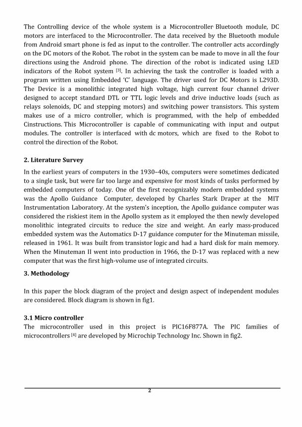
The Controlling device of the whole system is a Microcontroller. Bluetooth module, DC
motors are interfaced to the Microcontroller. The data received by the Bluetooth module
from Android smart phone is fed as input to the controller. The controller acts accordingly
on the DC motors of the Robot. The robot in the system can be made to move in all the four
directions using the Android phone. The direction of the robot is indicated using LED
indicators of the Robot system [3]. In achieving the task the controller is loaded with a
program written using Embedded ‘C’ language. The driver used for DC Motors is L293D.
The Device is a monolithic integrated high voltage, high current four channel driver
designed to accept standard DTL or TTL logic levels and drive inductive loads (such as
relays solenoids, DC and stepping motors) and switching power transistors. This system
makes use of a micro controller, which is programmed, with the help of embedded
Cinstructions. This Microcontroller is capable of communicating with input and output
modules. The controller is interfaced with dc motors, which are fixed to the Robot to
control the direction of the Robot.
2. Literature Survey
In the earliest years of computers in the 1930–40s, computers were sometimes dedicated
to a single task, but were far too large and expensive for most kinds of tasks performed by
embedded computers of today. One of the first recognizably modern embedded systems
was the Apollo Guidance Computer, developed by Charles Stark Draper at the MIT
Instrumentation Laboratory. At the system's inception, the Apollo guidance computer was
considered the riskiest item in the Apollo system as it employed the then newly developed
monolithic integrated circuits to reduce the size and weight. An early mass-produced
embedded system was the Automatics D-17 guidance computer for the Minuteman missile,
released in 1961. It was built from transistor logic and had a hard disk for main memory.
When the Minuteman II went into production in 1966, the D-17 was replaced with a new
computer that was the first high-volume use of integrated circuits.
3. Methodology
In this paper the block diagram of the project and design aspect of independent modules
are considered. Block diagram is shown in fig1.
3.1 Micro controller
The microcontroller used in this project is PIC16F877A. The PIC families of
microcontrollers [4] are developed by Microchip Technology Inc. Shown in fig2.

3
Fig1: Block diagram of Advanced Android Mobile Controlling Robot
Fig2: PIN DIAGRAM OF PIC16F877
This is the specification for PIC16F877A in Table1from Microchip. A single microcontroller [5] which is very easy to be assembled, program and also the price is very cheap. It cost less than 10 dollar. The good thing is that single unit can be purchased at that 10 dollar price. Unlike some other Integrated Circuit that must be bought at a minimum order quantity such as 1000 units or 2000 units or else you won’t be able to purchase it. One unit of PIC16F877A microcontroller can be programmed and erased many times.

4
Table1: PIC 16F877A Specification
RAM 368 bytes
EEPROM 256 bytes Flash Program Memory 8k(words)
Operating Frequency DC to 20MHz
I/O port Port A,B,C,D,E
3.2 Regulated Power Supply
Fig3: Regulated Power Supply
Power supply[6] is a supply of electrical power. A device or system that supplies electrical or other types of energy to an output load or group of loads is called a power supply unit or PSU. The term is most commonly applied to electrical energy supplies.A power supply in fig3 may include a power distribution system as well as primary or secondary sources of energy such as conversion of one form of electrical power to another desired form and voltage, typically involving converting AC line voltage to a well-regulated lower- voltage DC for electronic devices. Low voltage, low power DC power supply units are commonly integrated with the devices they supply, such as computers and household electronics.
3.3 LED:
A light-emitting diode (LED) is a semiconductor light source. LEDs are used as indicator lamps in many devices, and are increasingly used for lighting. Introduced as a practical electronic component in 1962, early LED’s emitted low-intensity red light, but modern versions are available across the visible, ultraviolet and infrared wavelengths, with very high brightness.

5
Fig4: Electrical Symbol & Polarities of LED
The LED shown in fig4 isbased on the semiconductor diode. When a diode is forward biased (switched on), electrons are able to recombine with holes within the device, releasing energy in the form of photons. This effect is called electroluminescence and the color of the light (corresponding to the energy of the photon) is determined by the energy gap of the semiconductor. An LED is usually small in area (less than 1 mm2), and integrated optical components are used to shape its radiation pattern and assist in reflection. LED’s present many advantages over incandescent light sources including lower energy consumption, longer lifetime, improved robustness, smaller size, faster switching, and greater durability and reliability.
1.4 Blue Tooth Module
‘Bluetooth’, the short-range radio link technology designed to "connect" an array of devices including mobile phones, PCs, and PDAs, and the strategic decisions that Motorola should make in incorporating this nascent technology into its product portfolio. The purpose of this paper will be to provide a high-level overview of the technology to the head of Motorola's Communications Enterprise, and prepare this corporate officer to be strategically and functionally conversant in the technology with subordinates that have direct responsibility for integrating Bluetooth into Motorola's product lines. The first sections of the paper detail the background of the Bluetooth technology and its associated Special-Interest Group, or SIG, (a conglomeration of firms that has sought to reduce market uncertainty, thereby expediting the diffusion of Bluetooth devices).
1.5 D.C. Motor
A DC motor uses electrical energy to produce mechanical energy, very typically through the interaction of magnetic fields and current carryingconductors. The reverse process, producing electrical energy from mechanical energy, is accomplished by an alternator, generator or dynamo. Many types of electric motors can be run as generators, and vice versa. The input of a DC motor[7] is current/voltage and its output is torque (speed).

6
Fig5: DC Motor
The DC motor in fig5 has two basic parts: the rotating part that is called the armature and the stationary part that includes coils of wire called the field coils. The stationary part is also called the stator.
3.6 DC Motor Driver
Both L293 and L293D are advance of triples i.equadruple half-H drivers[8]. The L293 in fig6 shows directional drive currents of up to 1 A at voltages from 4.5 V to 36 V. Design of these devises are to drive inductive loads such as relays, solenoids etc... Every input comes under TTL compatible. Every output is a complete totem-pole drive ckt. Drivers are used to enabled in combinational pairs of E and N, with drivers one and two enabled by 1,2EN and drivers Three and Four enabled by 3,4EN.When it gets enabled input is high, the corresponding drivers are enabled and their outputs are active and in phase with their inputs. If enabled input is low, those drivers are disabled and their outputs are inactive state and in the high-impedance phase. If the proper data inputs are given, then each pair of drivers forms a full-H (or bridge) reversible drive suitable for solenoid or motor console application.
Fig6: L293D IC diagram
3.7 PIC Compiler
PIC compiler is software used where the machine language code is written and compiled. After compilation, the machine source code is converted into hex code which is to be dumped into the microcontroller for further processing. PIC compiler also supports C language code. As we are going to use PIC Compiler, hence we also call it PIC C. The PCB, PCM, and PCH are separate compilers. PCB is for 12-bit op codes, PCM is for 14-bitopcodes, and PCH is for 16-bit op code PIC microcontrollers. Due to many similarities, all three compilers are covered in this reference manual. PIC C is not much different from a normal C program. If you know assembly, writing a C program is not a crisis. In PIC, we will have a main function, in which all your application specific work will be defined. In case of

7
embedded C, you do not have any operating system running in there. So you have to make sure that your program or main file should never exit. This can be done with the help of simple while (1) or for (;;) loop as they are going to run infinitely. We have to add header file for controller you are using, otherwise you will not be able to access registers related to peripherals.
4. Implementation
Schematic diagram and interfacing of PIC16F877 microcontroller with each module is
considered. The fig7 explains the interfacing section of each component with micro
controller, Bluetooth receiver module and DC motors and driver. The crystal oscillator [9]
connected to 13th and 14th pins of micro controller and regulated power supply is also
connected to micro controller and LED’s also connected to micro controller through
resistors and motor driver connected to micro controller. The detailed explanation of each
module interfacing with microcontroller is as follows:
Fig7: schematic diagram of Smart phone operated robot
4.1 Interfacing crystal oscillator with micro controller:
Figure8 explains crystal oscillatorand reset button which are connected to micro controller.
The two pins of oscillator are connected to the 13th and 14th pins of micro controller;
the purpose of external crystal oscillator is to speed up the execution part of instructions
per cycle and here the crystal oscillator having 20 MHz frequency. The 1st pin of the
microcontroller is referred as MCLR i.e., master clear pin or reset input pin is connected to
reset button or power-on-reset.

80
Fig8: crystal oscillator interfacing with micro controller
4.2 LED interfacing with PIC16F877A
LED stands for Light Emitting Diode[10] and these are connected to micro controller through resistors which is shown in fig9.
Fig 9: LED interfacing with PIC microcontroller

81
4.3 Interfacing DC Motor Driver to microcontroller
Fig10: Schematic Diagram of DC Motor Driver for Interfacing to Microcontroller
From the figure10 we can conclude that the DC Motoris not interfaced directly to the micro
controller. It is interfaced through its driver L293D .As shown in the above figure L293D is
a 16 pin IC in which the two motors are connected to pins 3, 6, 11,14 of L293D and in turn
the L293D is connected to Microcontroller to its Pins 4,5,6,7(Port A). If both the inputs to
the Motor Driver[10] is low and high the motor is in halt position. If the first output is high,
Second output is low then DC Motor moves forward.If the first output is low, second output
is high as shown figure11 then DC Motor moves reverse. Here the pins of motor driver
that is four input pins i/p1,i/p2,i/p3,i/p4 and heat sink pin and enable1 and enable2 pins
and ground pin and vs pins are connected to micro controller pins c0,c1,c2,c3,d0,d1,
ground, vdd respectively. Here L293D is the motor driver having one ‘H’ bridge inbuilt to
handle two motors by using two enable pins.
Figure11: Motor driver interfacing with micro controller

82
Advantages:
1. Operating the Robot wirelessly through mobile phone.
2. Usage of Android touch screen smart phone in performing the task.
3. Indicating Robot directions using LED indicators with Fast response.
4. Efficient and low cost design with Low power consumption.
Results
The project “Extended Version of Design and Implementation of a new Apk to Control Robot” was designed such that the robot can be operated using Android mobile phone. The controlling of the Robot is done wirelessly through Android smart phone using the Bluetooth feature[11] present in it.
5.1. Android Platform:
Android devices are powerful mobile computers and they have become more and more popular smart phones used worldwide. They have become more and more popular for software developers because of its powerful capabilities and open architecture, and is based on the java programming language. Because Android uses the Java programming language getting started with the Android API is easy; the API is open and allows easy access to the hardware components. Android devices provide numerous communication interfaces like USB, Wi-Fi and Bluetooth, that can be used to connect to the robot. We think it is a great platform for a robotic system control, because it’s much cheaper than any other ARM-based processing unit. We use android platform because it is the widest used in the word and runs the largest number of smart phones worldwide. The Android app is generally developed using JAVA language. This app was developed in “App Inventor” developed by MIT.
Fig. 12: Android App Development

83
Fig. 13: Android App Development using MIT App Inventor
Figure12 is the block diagram back- hand design for the application. The app has 5 buttons which give 5 different bytes in the output that has to be fed to the Microcontroller to process. For eg., if we press forward button ,the Bluetooth Module will give 1 byte at its output as shown in the figures 12 and 13. The app consists of the option in the main screen whether to use the accelerometer of the phone or to use the buttons to control the Robot. This app inventor brings out the revolution in the Embedded Systems & Robotics. The app invented by these searches for the Bluetooth devices along with their MAC addresses. The user just has to select the particular MAC Address. When a particular MAC is selected, the status shown on the screen is “Connected”. Now all the buttons are active and the app is connected with the robot. The mobile phone can now control the robot.
5.2 Mobile Application The Mobile application consists of 5 buttons viz. Right, Left, Forward, Reverse, Stop.
Fig14: Status- Not Connected Fig 15: Status- Connected

84
In fig14 the screen consists of an overlook of the app. Right now all the 5 buttons are disabled until the Bluetooth is connected. InFig 15, Bluetooth of the mobile is connected to another Bluetooth Module,the status shown in fig15 is “Connected”.
6. Conclusion Integrating features of all the hardware components used have been developed in it. Presence of every module has been reasoned out and placed carefully, thus contributing to the best working of the unit. Secondly, using highly advanced IC’s[12] with the help of growing technology, the project has been successfully implemented. Thus the project has been successfully designed and tested.
7.References
[1] Android Application Developed To Extend Health Monitoring Device Range And Real-
Time Patient Tracking 8-10 P. Szakacs-Simon, S. A. Moraru And L. Perniu , Ieee 9th
International Conference On Computational Cybernetics July 2013.
[2] Reliable Real-Time Applications On Android OS Bhupinder, S. Mongia Vijay K.
Madisetti, Fellow, IEEE June18, 2010.
[3] Robotics And Intelligent Systems In Support Of Society Raj Reddy, Carnegie Mellon
University, IEEE Intelligent Systems,Vol. 21, No. 3 May/June 2006.
[4] Application Of Pic Microcontroller For Online Monitoring And Fiber Fault Identification
5-7, Premadi, A. Dept. Of Electr., Electron., & Syst. Eng., Univ. Kebangsaan Malaysia,
Bangi, Malaysia Ab-Rahman, M.S. ; Ng Boon Chuan ; Saupe, M.N.M. ; Jumari, K. Ieee Aug.
2009.
[5] Implementation Of Gprs-Based Positioning System Using Pic Microcontroller , El-
Medany, W.M. Comput. Eng. Dept., Univ. Of Bahrain, Bahrain, Bahrain Alomary, A. ; Al-
Hakim, R. ; Al-Irhayim, S. ; Nousif, M.28-30 Ieee July 2010.
[6] Pic Microcontroller Based Svc For Reactive Power Compensation And Power Factor
Correction , Abhinav Sharma1 , Vishal Nayyar2 , S. Chatterji3 , Ritula Thakur3 , P.K.
Lehana*, International Journal Of Advanced Research In Computer Science And
Software Engineering Volume 3, Issue 9, September 2013.
[7] An H-Bridge Driver Using Gate Bias For DC Motor Control 6 , Hsin-Chuan Chen Dept. Of
Electron. Eng., St. John's Univ., New Taipei, Taiwan, IEEE June 2013
[8] Working And Analysis Of The H - Bridge Motor Driver Circuit Designed For Wheeled
Mobile Robots, Gupta, V. Univ. Inst. Of Eng. & Technol., Panjab Univ., Chandigarh,
India , IEEE 29 March 2010
[9] Crystal Oscillator With Dual Amplitude Stabilization Feedback Loop, Siwiec, K.Inst. Of
Microelectron. & Optoelectron., Warsaw Univ. Of Technol., Warsaw, Poland,IEEE 26 May
2012

85
[10] Status And Future Of High-Power Light-Emitting Diodes For Solid-State Lighting,
Krames, M.R. Philips Lumileds Lighting Co., San Jose, Ca Shchekin, O.B. ; Mueller-Mach,
Regina ; Mueller, Gerd O. ; Ling Zhou ; Harbers, G. ; Craford, M.G,Ieee 21 May 2007
[11] Bluetooth And Ieee 802.11b Coexistence: Analytical Performance Evaluation In
Fading Channels , Conti, A. Eis, Univ. Of Bologna, Italy Dardari, D. ; Pasolini, G. ;
Andrisano, O.,Ieee 19february 2003
[12] Hardware-Software Co-Design Of Embedded Systems [And Prolog] , Wolf, W.H. Dept.
Of Electr. Eng., Princeton Univ., Nj, Usa,Ieee 06 August 2002

86


![Cost Effective Bus Intimation System for the Public Using ...The microcontroller that has been used here belongs to PIC16F family. (PIC16F877a) [6]. Feature of PIC16F877a high performance](https://img.pdfslide.net/doc/110x75/5e907382aa017748036053c2/cost-effective-bus-intimation-system-for-the-public-using-the-microcontroller.jpg)