Embed Size (px)
Citation preview

EXTERNAL TURNINGTOOLHOLDERS
D1 - D44TURNING TOOLHOLDERS IDENTIFICATION SYSTEM D3
CLAMPING SYSTEM D6 - D7
PRODUCT LINEUP D4 - D5
TOOLHOLDERS FOR GENERAL PURPOSE D8 - D25
CN�� INSERT DCLN / DCLN-JCT / MCLN D8
PCLN D9
DN�� INSERT DDJN / DDJN-JCT / DDHN D12
PDJN / PDHN / MDJN D13
SN�� INSERT DSBN / MSSN D14
PSBN / PSKN / PSSN / PSDN D15
TN�� INSERT DTGN/ MTGN D16
PTGN / PTFN D17
WTJN / WTKN / WTEN D18
VN�� INSERT DVJN / DVLN / DVPN/ DVVN D20
MVJN / MVLN / MVVN D21
PVLN / PVPN / PVVN D22
RC�� INSERT PRGC / PRXC D23
RN�� INSERT PRGN D23
WN�� INSERT DWLN / MWLN D24
PWLN / WWLN D25
TOOLHOLDERS FOR CERAMIC TOOLS D26 - D35
CN�� INSERT CCLN / HCLN D26
DN�� INSERT CDJN D27
EN�� INSERT CELN D27
SN�� INSERT CSRN / HSRN / CS-N / CSKN / CSYN / CSSN D28
CSDN / HSDN D29
TN�� INSERT CTJN / CTUN D30
RN�� / RCGX INSERT CRSN / HRSN / CRDN / CRDC D31
CNGX INSERT CCLN-GX D32
DNGX INSERT CDHN-GX / CDJN-GX D33
SNGX INSERT CSRN-GX / CSDN-GX / CSSN-GX D34
CS-N-GX / CSKN-GX / CSYN-GX D35
TOOLHOLDERS FOR SOLID CBN TOOLS D36 - D40
CNM INSERT CCRN-A / CCLN-A D36
RNM INSERT CRSN-A / CRDN-A D37
SNM INSERT CSRN-A / CSKN-A / CSYN-A D38
CSSN-A / CSDN-A D39
TNM INSERT CTJN-A / CTUN-A D40
TOOLHOLDERS FOR BEARING MACHINING D41 - D42
RCMT INSERT PRGC-BE / PRGC-BF D41
SNMF INSERT CBSN D42
RECOMMENDED CUTTING CONDITIONS D43 - D44
D
D1
D2
D
TUR
NIN
G
HO
LDER
S
800.823.7284Visit us online at KyoceraPrecisionTools.com
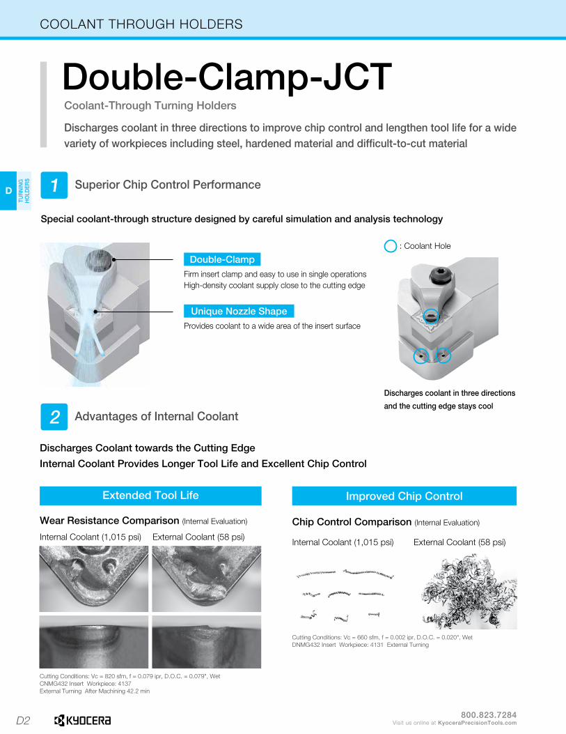
COOLANT THROUGH HOLDERS
Coolant-Through Turning Holders
Double-Clamp-JCTDischarges coolant in three directions to improve chip control and lengthen tool life for a wide variety of workpieces including steel, hardened material and difficult-to-cut material
Superior Chip Control Performance
Advantages of Internal Coolant
Special coolant-through structure designed by careful simulation and analysis technology
1
2
: Coolant Hole
Double-ClampFirm insert clamp and easy to use in single operations High-density coolant supply close to the cutting edge
Discharges coolant in three directions
and the cutting edge stays cool
Unique Nozzle ShapeProvides coolant to a wide area of the insert surface
Extended Tool Life Improved Chip Control
Wear Resistance Comparison (Internal Evaluation)
Internal Coolant (1,015 psi) External Coolant (58 psi)
Chip Control Comparison (Internal Evaluation)
Internal Coolant (1,015 psi) External Coolant (58 psi)
Cutting Conditions: Vc = 820 sfm, f = 0.079 ipr, D.O.C. = 0.079", WetCNMG432 Insert Workpiece: 4137External Turning After Machining 42.2 min
Cutting Conditions: Vc = 660 sfm, f = 0.002 ipr, D.O.C. = 0.020", WetDNMG432 Insert Workpiece: 4131 External Turning
Discharges Coolant towards the Cutting Edge
Internal Coolant Provides Longer Tool Life and Excellent Chip Control

D3
H
CU
T-OFF
J
THR
EADIN
G
M
MILLIN
G
N
QUICK CHANG
ETO
OLIN
G
R
TECH
NIC
AL
P
SPARE PAR
TS
T
IND
EX
D
TUR
NIN
G
HO
LDER
S
F
BO
RIN
G
B
TUR
NIN
G
INSER
TS
G
GR
OO
VING
C
CB
N/PC
D
INSER
TS
E
SMALL
TOO
LS
K
DR
ILLING
L
SOLID
TOO
LS
A
INSER
T G
RAD
ES
800.823.7284Visit us online at KyoceraPrecisionTools.com
EXTERNAL TOOLHOLDER IDENTIFICATION SYSTEM
A : Anchor Pin Style
C : Clamp Only
D : Double Clamp
M : Clamp and Lock Pin
P : Lock Pin Only (or Lever Lock)
S : Screw Only
W : Wedge Only
� Clamping System
R : Round
S : Square
T : Triangle
C : 80˚ Diamond
D : 55˚ Diamond
V : 35˚ Diamond
W : 80˚ Trigon
R : Round
� Insert Shape
This position shall be a significant number which indicates the holder cross section. For square shanks this number will represent the number of sixteenths of width and height. For rectangular holders the first digit represents the number of eighths of width and the second digit the number of quarters of height, except the following toolholder: 1-1/4 x 1-1/2 which is given the number 91.
� Toolholder Shank Size
D�
D�
C�
C�
L�
L�
N�
N�
R�
R�
16�
20�
4�
D�
20�
K�
12� �
� Cutting Edge Angle � Others
Optional Code
Optional Mark or Number
� Shank Width
Shank Width(mm)
� Shank Height
Shank Height(mm)
� Insert Relief Angle
�
B : 5˚ Positive
C : 7˚ Positive
D : 15˚ Positive
E : 20˚ Positive
N : 0˚ Negative
P : 11˚ Positive
ANSI(inch)
ISO(metric)
LENGTH AND WIDTH LENGTH AND SIDE
A - 4.000 Back and End M - 4.000 Front and End
B - 4.500 Back and End N - 4.500 Front and End
C - 5.000 Back and End P - 5.000 Front and End
D - 6.000 Back and End R - 6.000 Front and End
E - 7.000 Back and End S - 7.000 Front and End
F - 8.000 Back and End T - 8.000 Front and End
G - 5.500 Back and End U - 5.500 Front and End
* NOTE: All qualified dimensions are given to a tolerance of 0.003" over a master gauge insert radius based on the standard shown.
Insert I.C. Radius
1/4" - 5/16" 0.015"
3/8" - 1/2" 0.031"
5/8" - 3/4" 0.047"
1" 0.062"
� Qualified Control
Number of 1/8ths on 1/4" I.C. and over.
� Insert Size I.C.
• Specifications may change without prior notice.• Due to the installation size constraints on the machine, the toolholder length of some products may not match with the symbol.
� Hand of Tool
R : Right-hand
L : Left-hand
N : Neutral
� Toolholder Length
L(mm)
A : 32 J : 110 S : 250
B : 40 K : 125 T : 300
C : 50 L : 140 U : 350
D : 60 M : 150 V : 400
E : 70 N : 160 W : 450
F : 80 P : 170 Y : 500
G : 90 Q : 180 X : Special
H : 100 R : 200
� Insert Size
(mm)
L
D
L
V
T
L
C
L
L L
R S
-
-

D4
D
TUR
NIN
G
HO
LDER
S
800.823.7284Visit us online at KyoceraPrecisionTools.com
PRODUCT LINEUP
� General Purpose Turning Holders
ApplicableInsertShape
CN.. WN.. TN.. DN.. RC.. RN.. VN..
Application External / Facing External / Facing / Copying External / Facing / Copying / Undercutting
Cutting Edge Angle 95° 105° 107.5° Special 117.5°
Lever Lock(Pin Lock)
PCLN PWLN PDHN PRGC PRXC PRGN PVPN (Pin Lock)
Ref. Page � D9 � D25 � D13 � D23 � D23 � D23 � D22
Wedge Lock
WWLN WTKNRef. Page � D25 � D18
Double Clamp
DCLN (-JCT) DWLN DDHN DVPNRef. Page � D8 � D24 � D12 � D20
Multi-Lock
MCLN MWLNRef. Page � D8 � D24
ApplicableInsertShape
VN.. DN.. SN.. TN.. SN.. SN.. TN.. SN.. TN..
TN..
Application External / Copying External / Chamfering External / Facing / Chamfering External Facing
Cutting Edge Angle 72.5° 95° 93° 45° 60° 45° 75° 91° 15° -1°
Lever Lock(Pin Lock)
PVVN(Pin Lock)
PVLN(Pin Lock) PDJN PSDN PSSN PSBN PTGN PSKN PTFN
Ref. Page � D22 � D22 � D13 � D15 � D15 � D15 � D17 � D15 � D17
Wedge Lock
WTJN WTENRef. Page � D18 � D18
Double Clamp
DVVN DVJN / DVLN DDJN (-JCT) DSBN DTGNRef. Page � D20 � D20 � D12 � D14 � D16
Multi-Lock
MVVN MVJN / MVLN MDJN MSSN MTGNRef. Page � D21 � D21 � D13 � D14 � D16
D5
H
CU
T-OFF
J
THR
EADIN
G
M
MILLIN
G
N
QUICK CHANG
ETO
OLIN
G
R
TECH
NIC
AL
P
SPARE PAR
TS
T
IND
EX
D
TUR
NIN
G
HO
LDER
S
F
BO
RIN
G
B
TUR
NIN
G
INSER
TS
G
GR
OO
VING
C
CB
N/PC
D
INSER
TS
E
SMALL
TOO
LS
K
DR
ILLING
L
SOLID
TOO
LS
A
INSER
T G
RAD
ES
800.823.7284Visit us online at KyoceraPrecisionTools.com
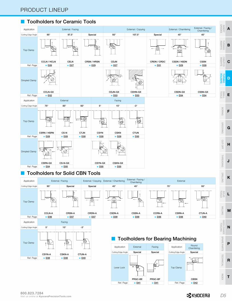
PRODUCT LINEUP
� Toolholders for Ceramic ToolsApplication External / Facing External / Copying External / Chamfering External / Facing /
Chamfering
Cutting Edge Angle 95° 97.5° Special 93° 107.5° Special 45° 45°
Top Clamp
CCLN / HCLN CELN CRSN / HRSN CDJN CRDN / CRDC CSDN / HSDN CSSN
Ref. Page � D26 � D27 � D29 � D27 � D31 � D29 � D28
Dimpled Clamp
CCLN-GX CDJN-GX CDHN-GX CSDN-GX CSSN-GXRef. Page � D32 � D33 � D33 � D34 � D34
Application External Facing
Cutting Edge Angle 75° 85° 93° 5° 15° -3°
Top Clamp
CSRN / HSRN CS-N CTJN CSYN CSKN CTUN
Ref. Page � D28 � D28 � D30 � D28 � D28 � D30
Dimpled Clamp
CSRN-GX CS-N-GX CSYN-GX CSKN-GXRef. Page � D34 � D35 � D35 � D35
� Toolholders for Solid CBN ToolsApplication External / Facing External / Copying External / Chamfering External / Facing /
Chamfering External
Cutting Edge Angle 95° Special Special 45° 45° 75° 93°
Top Clamp
CCLN-A CRSN-A CRDN-A CSDN-A CSSN-A CCRN-A CSRN-A CTJN-A
Ref. Page � D36 � D37 � D37 � D39 � D39 � D36 � D38 � D40
Application Facing
Cutting Edge Angle 5° 15° -3°
Top Clamp
CSYN-A CSKN-A CTUN-A
Ref. Page � D38 � D38 � D40
� Toolholders for Bearing MachiningApplication External Facing
Cutting Edge Angle Special Special
Lever Lock
PRGC-BE PRGC-BF
Ref. Page � D41 � D41
Application Round Chamfering
Cutting Edge Angle Special
Top Clamp
CBSN
Ref. Page � D42
D6
D
TUR
NIN
G
HO
LDER
S
800.823.7284Visit us online at KyoceraPrecisionTools.com
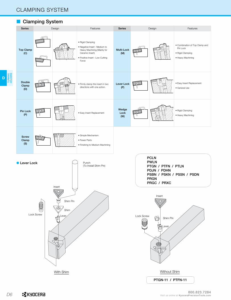
With Shim
PCLNPWLNPTGN / PTFN / PTLNPDJN / PDHNPSBN / PSKN / PSSN / PSDNPRGNPRGC / PRXC
PTGN-11 / PTFN-11
Without Shim
CLAMPING SYSTEM
� Clamping SystemSeries Design Features Series Design Features
Top Clamp(C)
• Rigid Clamping
• Negative Insert : Medium to Heavy Machining (Mainly for Ceramic Insert)
• Positive Insert : Low Cutting Force
Multi-Lock (M)
• Combination of Top Clamp and Pin Lock
• Rigid Clamping
• Heavy Machining
Double Clamp
(D)
• Firmly clamp the insert in two directions with one action.
Lever Lock (P)
• Easy Insert Replacement
• General Use
Pin Lock (P)
• Easy Insert ReplacementWedgeLock (W)
• Rigid Clamping
• Heavy Machining
Screw Clamp
(S)
• Simple Mechanism
• Fewer Parts
• Finishing to Medium Machining
� Lever Lock

D7
H
CU
T-OFF
J
THR
EADIN
G
M
MILLIN
G
N
QUICK CHANG
ETO
OLIN
G
R
TECH
NIC
AL
P
SPARE PAR
TS
T
IND
EX
D
TUR
NIN
G
HO
LDER
S
F
BO
RIN
G
B
TUR
NIN
G
INSER
TS
G
GR
OO
VING
C
CB
N/PC
D
INSER
TS
E
SMALL
TOO
LS
K
DR
ILLING
L
SOLID
TOO
LS
A
INSER
T G
RAD
ES
800.823.7284Visit us online at KyoceraPrecisionTools.com
� Wedge Lock
WWLN
WTJNWTKNWTEN
� Multi Lock � Top Clamp
MCLNMDJNMSSNMTGNMVJNMVVNMWLN
CCLN / HCLNCTJN / CTUNCDHN / CDJNCELNCSRN / HSRN / CS-N / CSKNCSYN / CSSN / CSDN / HSDN*CRSN / HRSN / *CRDN / CRDC
* Chipbreaker is not included with CRSN / CRDN.
� Double Clamp
DCLN DDJN / DDHN DSBN DTGN DVLN / DVJN / DVPN / DVVNDWLN
Insert
Shim Screw
Shim
Spring
Clamp
Screw
DDJN
CLAMPING SYSTEM
D8
D
TUR
NIN
G
HO
LDER
S
(Customer Service) 800.823.7284 - Option 1(Technical Support) 800.823.7284 - Option 2
Visit us online at KyoceraPrecisionTools.comÞ : Standard Item � : Phaseout Item (will be removed from next catalog)
Contact your local Kyocera sales engineer to upgrade old products to new technology
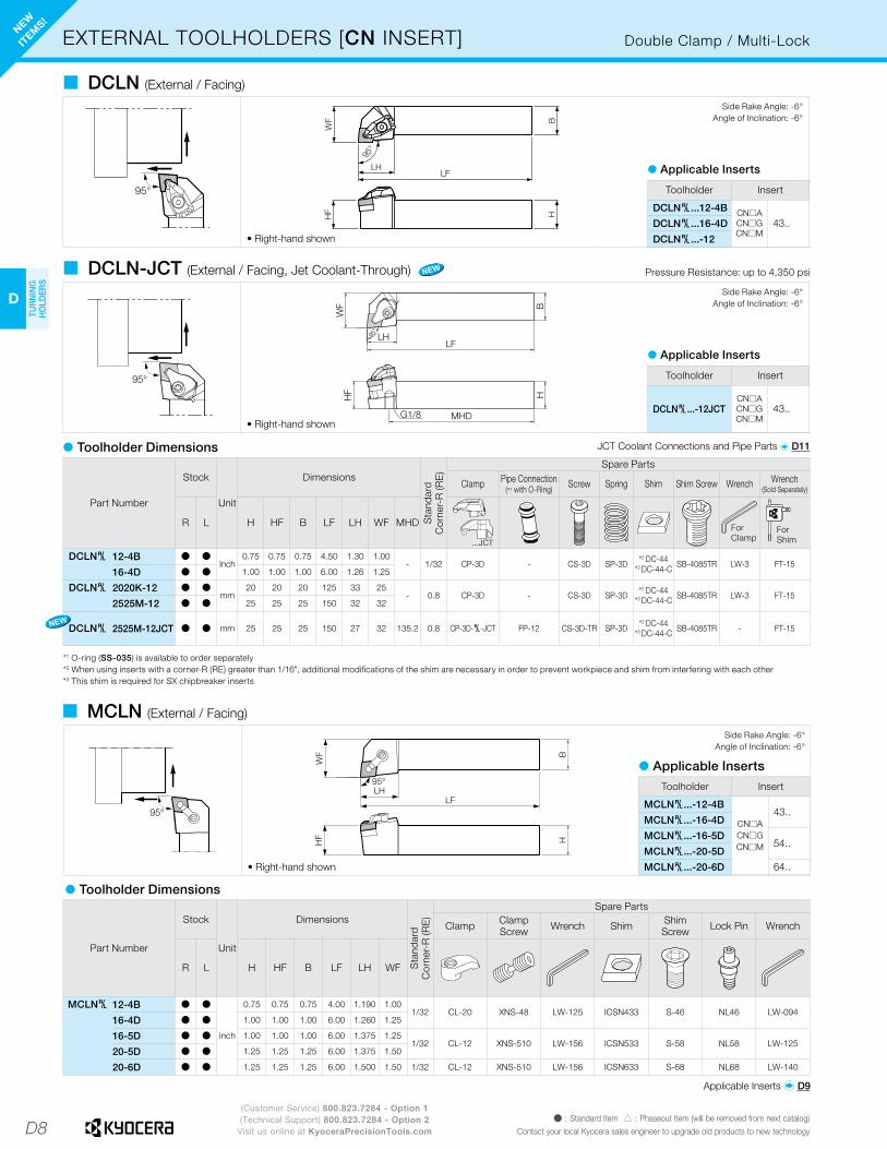
EXTERNAL TOOLHOLDERS [CN INSERT] Double Clamp / Multi-Lock
� Toolholder Dimensions
� DCLN (External / Facing)
� DCLN-JCT (External / Facing, Jet Coolant-Through)
Part Number
Stock
Unit
Dimensions
Sta
ndar
dC
orne
r-R
(RE
)
Spare Parts
Clamp Pipe Connection(*1 with O-Ring) Screw Spring Shim Shim Screw Wrench Wrench
(Sold Separately)
R L H HF B LF LH WF MHD
...JCT
ForClamp
ForShim
DCLN§ 12-4B Þ ÞInch
0.75 0.75 0.75 4.50 1.30 1.00- 1/32 CP-3D - CS-3D SP-3D *2 DC-44
*3 DC-44-C SB-4085TR LW-3 FT-1516-4D Þ Þ 1.00 1.00 1.00 6.00 1.26 1.25
DCLN§ 2020K-12 Þ Þmm
20 20 20 125 33 25- 0.8 CP-3D - CS-3D SP-3D *2 DC-44
*3 DC-44-C SB-4085TR LW-3 FT-152525M-12 Þ Þ 25 25 25 150 32 32
DCLN§ 2525M-12JCT Þ Þ mm 25 25 25 150 27 32 135.2 0.8 CP-3D-§-JCT FP-12 CS-3D-TR SP-3D *2 DC-44*3 DC-44-C SB-4085TR - FT-15
*1 O-ring (SS-035) is available to order separately*2 When using inserts with a corner-R (RE) greater than 1/16", additional modifications of the shim are necessary in order to prevent workpiece and shim from interfering with each other*3 This shim is required for SX chipbreaker inserts
95°
HF H
95°
WF
LFLH
B
• Right-hand shown
95°
B
LFW
FH
F H
95°
LH
MHD G1/8• Right-hand shown
Side Rake Angle: -6°Angle of Inclination: -6°
Side Rake Angle: -6°Angle of Inclination: -6°
Toolholder Insert
DCLN§...12-4B CN�ACN�GCN�M
43..DCLN§...16-4D
DCLN§...-12
� Applicable Inserts
Toolholder Insert
DCLN§...-12JCTCN�ACN�GCN�M
43..
� Applicable Inserts
� Toolholder Dimensions
95°
LH95°
WF
LF
BHHF
• Right-hand shown
� MCLN (External / Facing)
Part Number
Stock
Unit
Dimensions
Sta
ndar
dC
orne
r-R
(RE
)
Spare Parts
Clamp Clamp Screw Wrench Shim Shim
Screw Lock Pin Wrench
R L H HF B LF LH WF
MCLN§ 12-4B Þ Þ
inch
0.75 0.75 0.75 4.00 1.190 1.001/32 CL-20 XNS-48 LW-125 ICSN433 S-46 NL46 LW-094
16-4D Þ Þ 1.00 1.00 1.00 6.00 1.260 1.25
16-5D Þ Þ 1.00 1.00 1.00 6.00 1.375 1.251/32 CL-12 XNS-510 LW-156 ICSN533 S-58 NL58 LW-125
20-5D Þ Þ 1.25 1.25 1.25 6.00 1.375 1.50
20-6D Þ Þ 1.25 1.25 1.25 6.00 1.500 1.50 1/32 CL-12 XNS-510 LW-156 ICSN633 S-68 NL68 LW-140
Side Rake Angle: -6°Angle of Inclination: -6°
Pressure Resistance: up to 4,350 psi
Toolholder Insert
MCLN§...-12-4B
CN�ACN�GCN�M
43..MCLN§...-16-4D
MCLN§...-16-5D54..
MCLN§...-20-5D
MCLN§...-20-6D 64..
� Applicable Inserts
Applicable Inserts � D9
NEW
ITEM
S!
NEW
NEW
JCT Coolant Connections and Pipe Parts � D11

D9
H
CU
T-OFF
J
THR
EADIN
G
M
MILLIN
G
N
QUICK CHANG
ETO
OLIN
G
R
TECH
NIC
AL
P
SPARE PAR
TS
T
IND
EX
D
TUR
NIN
G
HO
LDER
S
F
BO
RIN
G
B
TUR
NIN
G
INSER
TS
G
GR
OO
VING
C
CB
N/PC
D
INSER
TS
E
SMALL
TOO
LS
K
DR
ILLING
L
SOLID
TOO
LS
A
INSER
T G
RAD
ES
(Customer Service) 800.823.7284 - Option 1(Technical Support) 800.823.7284 - Option 2
Visit us online at KyoceraPrecisionTools.comÞ : Standard Item � : Phaseout Item (will be removed from next catalog)Contact your local Kyocera sales engineer to upgrade old products to new technology
EXTERNAL TOOLHOLDERS [CN INSERT]
Application Finishing Finishing-Medium Finishing Finishing-Medium Finishing-Medium Finishing-Medium Medium-Roughing Medium-Roughing Medium-Roughing Medium-Roughing / High Feed Rate
Insert
WF (Wiper) WE (Wiper) PP PQ CQ CJ GS PG PS PT
Size 43.. 43.. 43.. 43.. 43.., 54.. 43.., 54.. 33.., 43.. 43.. 43.., 54.. 43.., 54..
Ref. Page � B16 � B16 � B16 � B16 � B17 � B17 � B17 � B17 � B17 � B18
� Applicable Inserts
Lever Lock
� Toolholder Dimensions
� PCLN (External / Facing)
• Right-hand shown
Side Rake Angle: -6°Angle of Inclination: -6°
Toolholder Insert
PCLN§...12-3BCN�G 33..
PCLN§...16-3D
PCLN§...12-4B CN�ACN�GCN�M
43..PCLN§...16-4D
PCLN§...-09 CN�G 33..
PCLN§...-12 CN�ACN�GCN�M
43..
PCLN§...-16 54..
� Applicable Inserts
Part Number
Stock
Unit
Dimensions
Sta
ndar
dC
orne
r-R
(RE
) Spare Parts
Lever Lock Screw Shim Shim Pin Punch Wrench
R L H HF B LF LH WF
FH
LW
PCLN§ 12-3B Þ
Inch
0.75 0.75 0.75 4.50 0.87 1.00 1/32 LL-1N LS-1N LC-32N LSP-1 PC-1 FH-2.5
PCLN§ 12-4B Þ 0.75 0.75 0.75 4.50 1.06 1.001/32 LL-2N LS-2N
LC-42N*2 LC-42N-20*3 LC-42N-C
LSP-2 PC-2 LW-316-4D Þ 1.00 1.00 1.00 6.00 1.06 1.25
PCLN§ 1616H-09 Þ Þ
mm
16 16 16 100 22 20
0.8 LL-1N LS-1N LC-32N LSP-1 PC-1 FH-2.52020K-09 Þ Þ 20 20 20 125 22 25
2525M-09 Þ Þ 25 25 25 150 22 32
PCLN§ 1616H-12 Þ 16 16 16 100 27 20
0.8 LL-2N LS-2NLC-42N
*2 LC-42N-20*3 LC-42N-C
LSP-2 PC-2 LW-3
2020H-12*1 Þ 20 20 20 100 27 25
2020K-12 Þ Þ 20 20 20 125 27 25
2525M-12 Þ Þ 25 25 25 150 27 32
3225P-12 Þ Þ 32 32 25 170 27 32
PCLN§ 2525M-16 Þ Þ 25 25 25 150 32 320.8 LL-5N LS-4N LC-53N
*3 LC-53N-C LSP-3 - LW-33232P-16 Þ Þ 32 32 32 170 32 40
*1 Short shank type.*2 When using inserts whose corner-R(RE) is greater than 1/16", additional modifications of the shim are necessary in order to prevent workpiece and shim from interfering with each other.*3 This shim is required for SX chipbreaker inserts.
Application Roughing RoughingSingle Sided / Roughing /
High Feed Rate Finishing Medium Soft Steel / Small D.O.C.
Soft Steel / Finishing
Soft Steel / Medium
Soft Steel / Roughing
Stainless Steel / Finishing
Insert
Standard PH PX §-S § XF XP XQ XS MQ
Size 43.., 54.., 64.. 43.., 54.., 64.. 43.., 54.., 64.. 33.. 33.., 43.. 43.. 43.. 43.. 43.. 43..
Ref. Page � B18 � B18 � B19 � B22 � B22 � B19 � B19 � B19 � B19 � B20
Application Stainless Steel /Medium-Roughing
Stainless Steel / Medium-Roughing Cast Iron Cast Iron Cast Iron Cast Iron Cast Iron Cast Iron Cast Iron Cast Iron
Insert
MS MU KQ KG KH C ZS GC Without Chipbreaker Ceramic
Size 43.. 43.., 54.., 64.. 43.. 43.. 43.. 43.. 43.. 43.. 43.. 43..Ref. Page � B20 � B20 � B22 � B21 � B21 � B21 � B21 � B21 � B21 � B106
Application Non-ferrousMetals
Non-ferrousMetals
Non-ferrousMetals
Heat-Resistant Alloys
Heat-Resistant AlloyRoughing
Heat-Resistant AlloyRoughing Hard Materials
Insert
A3 AH PCD SQ SG §-SX CBN
Size 43.. 43.. 43.. 43.., 54.., 64.. 43.., 54.., 64.. 43.., 54.., 64.. 43..Ref. Page � B22 � B22 � C23 � B20 � B20 � B21 � C6, C7 Recommended Cutting Conditions � D43-D44

D10
D
TUR
NIN
G
HO
LDER
S
(Customer Service) 800.823.7284 - Option 1(Technical Support) 800.823.7284 - Option 2
Visit us online at KyoceraPrecisionTools.comÞ : Standard Item � : Phaseout Item (will be removed from next catalog)
Contact your local Kyocera sales engineer to upgrade old products to new technology
Piping Installation Guide
· Even without a high pressure pump, internal coolant can be used at a normal pressure
· Banjo bolt available for angled hose connection and can be used in a variety of machines
Easy Connection with High Pressure Hose and Joint
Easy Coolant Connections
2. Washer
1. Banjo Bolt
2. Washer 1. Joint
3. Hose
� Improved performance and stable machining with internal coolant even with low pressure
Pressure Range Tool Life Chip Control Notes
~ 290 psi (Low Pressure) Good Poor Tool life is improved even when machining with low pressure coolant systems
290 psi ~ 1,015 psi (Medium Pressure) Excellent Good Improved tool life and chip control performance
1,015 psi ~ 2,175 psi (High Pressure) Excellent Excellent Chips become smaller and are easily evacuated
2,175 psi ~ 4,350 psi (Extra High Pressure) Excellent Excellent Chips are smaller and high-speed machining of heat-resistant alloys is possible
COOLANT THROUGH HOLDER PIPING PARTS
Mac
hine
Mac
hine
G1/8M10
G1/8M10
UNF3/8 ST ST
AN AN
UNF3/8
UNF3/8
UNF3/8
G1/8
G1/8
G1/8
JCT Toolholder
2. Washer1. Joint / Banjo Bolt
12
12 1 2
1 23
3
3. Hose2. Washer1. Joint / Banjo Bolt
D11
H
CU
T-OFF
J
THR
EADIN
G
M
MILLIN
G
N
QUICK CHANG
ETO
OLIN
G
R
TECH
NIC
AL
P
SPARE PAR
TS
T
IND
EX
D
TUR
NIN
G
HO
LDER
S
F
BO
RIN
G
B
TUR
NIN
G
INSER
TS
G
GR
OO
VING
C
CB
N/PC
D
INSER
TS
E
SMALL
TOO
LS
K
DR
ILLING
L
SOLID
TOO
LS
A
INSER
T G
RAD
ES
(Customer Service) 800.823.7284 - Option 1(Technical Support) 800.823.7284 - Option 2
Visit us online at KyoceraPrecisionTools.comÞ : Standard Item � : Phaseout Item (will be removed from next catalog)Contact your local Kyocera sales engineer to upgrade old products to new technology
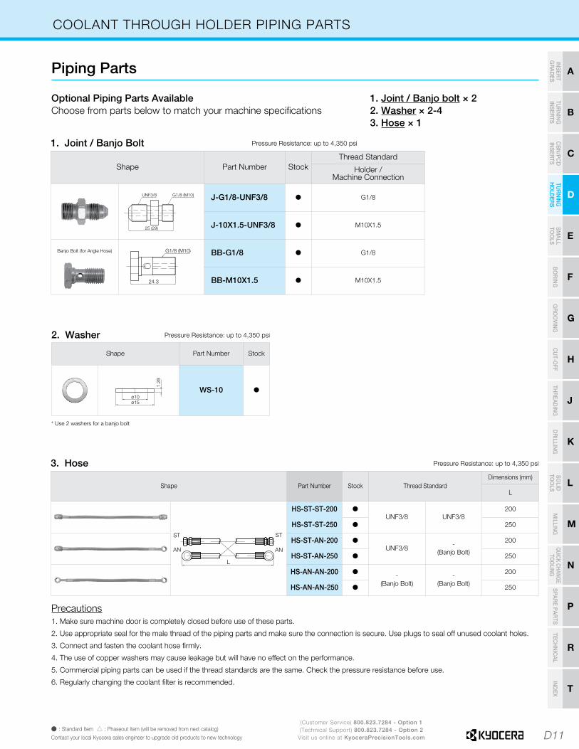
COOLANT THROUGH HOLDER PIPING PARTS
Optional Piping Parts Available Choose from parts below to match your machine specifications
Piping Parts
1. Joint / Banjo bolt × 22. Washer × 2-43. Hose × 1
Shape Part Number StockThread Standard
Holder /Machine Connection
25 (29)
G1/8 (M10) UNF3/8 J-G1/8-UNF3/8 Þ G1/8
J-10X1.5-UNF3/8 Þ M10X1.5
Banjo Bolt (for Angle Hose) G1/8 (M10)
24.3
BB-G1/8 Þ G1/8
BB-M10X1.5 Þ M10X1.5
Shape Part Number Stock Thread StandardDimensions (mm)
L
L
ST ST
AN AN
HS-ST-ST-200 ÞUNF3/8 UNF3/8
200
HS-ST-ST-250 Þ 250
HS-ST-AN-200 ÞUNF3/8 -
(Banjo Bolt)
200
HS-ST-AN-250 Þ 250
HS-AN-AN-200 Þ-
(Banjo Bolt)-
(Banjo Bolt)
200
HS-AN-AN-250 Þ 250
Shape Part Number Stock
1.28
ø15ø10
WS-10 Þ
1. Joint / Banjo Bolt
3. Hose
2. Washer
Pressure Resistance: up to 4,350 psi
Pressure Resistance: up to 4,350 psi
Pressure Resistance: up to 4,350 psi
* Use 2 washers for a banjo bolt
Precautions1. Make sure machine door is completely closed before use of these parts.
2. Use appropriate seal for the male thread of the piping parts and make sure the connection is secure. Use plugs to seal off unused coolant holes.
3. Connect and fasten the coolant hose firmly.
4. The use of copper washers may cause leakage but will have no effect on the performance.
5. Commercial piping parts can be used if the thread standards are the same. Check the pressure resistance before use.
6. Regularly changing the coolant filter is recommended.
D12
D
TUR
NIN
G
HO
LDER
S
(Customer Service) 800.823.7284 - Option 1(Technical Support) 800.823.7284 - Option 2
Visit us online at KyoceraPrecisionTools.comÞ : Standard Item � : Phaseout Item (will be removed from next catalog)
Contact your local Kyocera sales engineer to upgrade old products to new technology
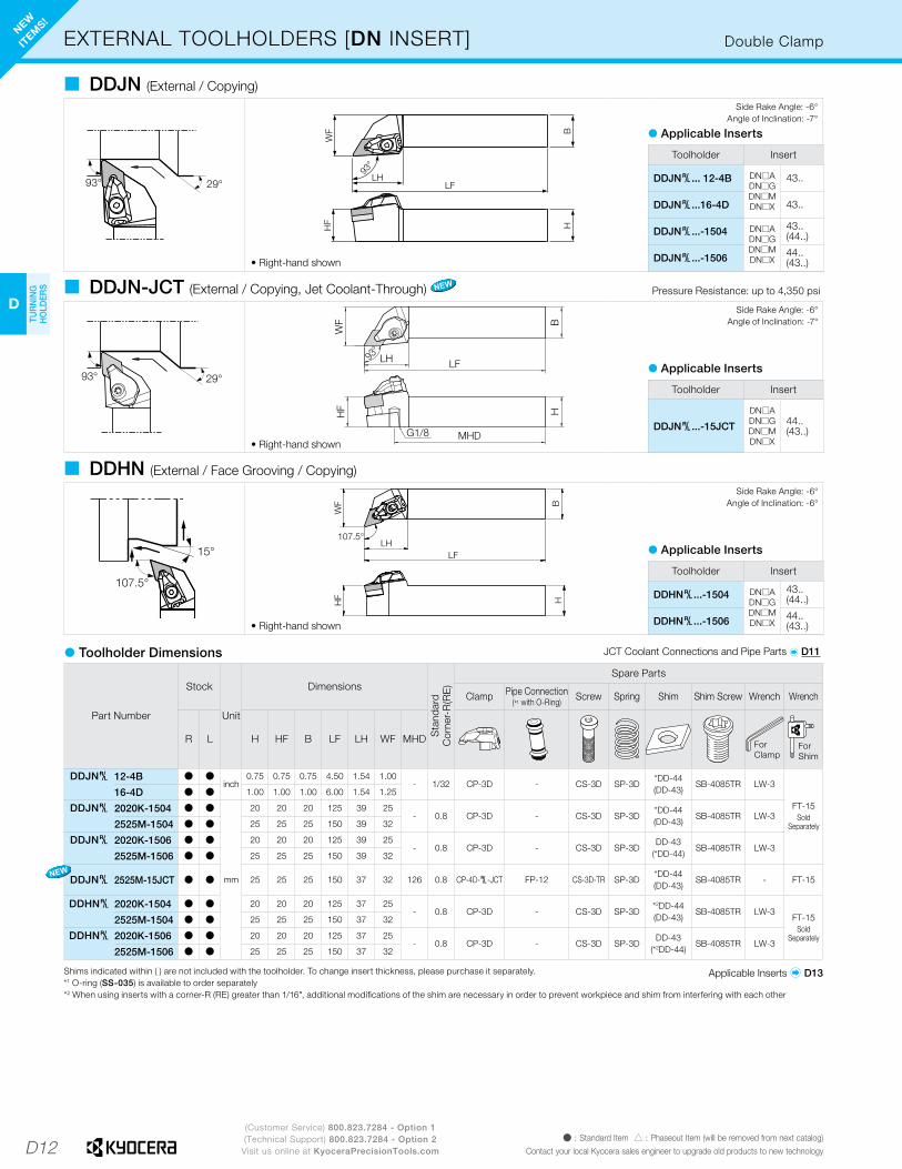
EXTERNAL TOOLHOLDERS [DN INSERT] Double Clamp
93° 29°
HF H
B
WF
93°
LHLF
• Right-hand shown
� DDJN (External / Copying)Side Rake Angle: -6°
Angle of Inclination: -7°
Shims indicated within ( ) are not included with the toolholder. To change insert thickness, please purchase it separately.*1 O-ring (SS-035) is available to order separately*2 When using inserts with a corner-R (RE) greater than 1/16", additional modifications of the shim are necessary in order to prevent workpiece and shim from interfering with each other
Toolholder Insert
DDJN§... 12-4B DN�ADN�GDN�MDN�X
43..
DDJN§...16-4D 43..
DDJN§...-1504 DN�ADN�GDN�MDN�X
43..(44..)
DDJN§...-1506 44..(43..)
� Applicable Inserts
B
WF
H
93°
HF
LFLH
MHDG1/8• Right-hand shown
107.5°
15°B
H
LHLF
107.5°
WF
HF
• Right-hand shown
� DDJN-JCT (External / Copying, Jet Coolant-Through)
� DDHN (External / Face Grooving / Copying)
Toolholder Insert
DDJN§...-15JCT
DN�ADN�GDN�MDN�X
44..(43..)
Toolholder Insert
DDHN§...-1504 DN�ADN�GDN�MDN�X
43..(44..)
DDHN§...-1506 44..(43..)
� Applicable Inserts
� Applicable Inserts
Side Rake Angle: -6°Angle of Inclination: -7°
Side Rake Angle: -6°Angle of Inclination: -6°
� Toolholder Dimensions
Part Number
Stock
Unit
Dimensions
Sta
ndar
dC
orne
r-R
(RE
)
Spare Parts
Clamp Pipe Connection(*1 with O-Ring) Screw Spring Shim Shim Screw Wrench Wrench
R L H HF B LF LH WF MHD ForClamp
ForShim
DDJN§ 12-4B Þ Þinch
0.75 0.75 0.75 4.50 1.54 1.00- 1/32 CP-3D - CS-3D SP-3D
*DD-44(DD-43)
SB-4085TR LW-3
FT-15Sold
Separately
16-4D Þ Þ 1.00 1.00 1.00 6.00 1.54 1.25
DDJN§ 2020K-1504 Þ Þ
mm
20 20 20 125 39 25- 0.8 CP-3D - CS-3D SP-3D
*DD-44(DD-43)
SB-4085TR LW-32525M-1504 Þ Þ 25 25 25 150 39 32
DDJN§ 2020K-1506 Þ Þ 20 20 20 125 39 25- 0.8 CP-3D - CS-3D SP-3D
DD-43(*DD-44)
SB-4085TR LW-32525M-1506 Þ Þ 25 25 25 150 39 32
DDJN§ 2525M-15JCT Þ Þ 25 25 25 150 37 32 126 0.8 CP-4D-§-JCT FP-12 CS-3D-TR SP-3D*DD-44(DD-43)
SB-4085TR - FT-15
DDHN§ 2020K-1504 Þ Þ 20 20 20 125 37 25- 0.8 CP-3D - CS-3D SP-3D
*2DD-44(DD-43)
SB-4085TR LW-3FT-15
SoldSeparately
2525M-1504 Þ Þ 25 25 25 150 37 32
DDHN§ 2020K-1506 Þ Þ 20 20 20 125 37 25- 0.8 CP-3D - CS-3D SP-3D
DD-43(*2DD-44)
SB-4085TR LW-32525M-1506 Þ Þ 25 25 25 150 37 32
Applicable Inserts � D13
NEW
ITEM
S!
NEW
93° 29°
Pressure Resistance: up to 4,350 psi
JCT Coolant Connections and Pipe Parts � D11
NEW
D13
H
CU
T-OFF
J
THR
EADIN
G
M
MILLIN
G
N
QUICK CHANG
ETO
OLIN
G
R
TECH
NIC
AL
P
SPARE PAR
TS
T
IND
EX
D
TUR
NIN
G
HO
LDER
S
F
BO
RIN
G
B
TUR
NIN
G
INSER
TS
G
GR
OO
VING
C
CB
N/PC
D
INSER
TS
E
SMALL
TOO
LS
K
DR
ILLING
L
SOLID
TOO
LS
A
INSER
T G
RAD
ES
(Customer Service) 800.823.7284 - Option 1(Technical Support) 800.823.7284 - Option 2
Visit us online at KyoceraPrecisionTools.comÞ : Standard Item � : Phaseout Item (will be removed from next catalog)Contact your local Kyocera sales engineer to upgrade old products to new technology
Application Roughing Single Sided RoughingHigh Feed Rate Finishing Medium Soft Steel / Finishing Soft Steel / Medium Soft Steel /
RoughingStainless Steel /
FinishingStainless Steel /
Medium-RoughingStainless Steel /
Medium-Roughing
Insert
Size 43.., 44.. 43.., 44.. 33.. 33.., 43.. 43.., 44.. 43.., 44.. 43.. 43.., 44.. 43.., 44.. 43.., 44..
Ref. Page � B26 � B26 � B30 � B30 � B26 � B26 � B26 � B27 � B28 � B28
Application Heat-Resistant AlloyRoughing
Stainless Steel /Medium-Roughing Cast Iron Cast Iron Cast Iron Cast Iron Cast Iron Cast Iron Cast Iron Non-ferrous Metals
Insert
Size 43.. 43.., 44.. 43.., 44.. 43.., 44.. 43.., 44.. 43.., 44.. 43.., 44.. 43.., 44.. 43.., 44.. 43..Ref. Page � B28 � B27 � B29 � B29 � B29 � B29 � B29 � B29 � B107 � B30
Application Non-ferrous Metals Non-ferrous Metals Heat-Resistant Alloys Hard Materials
Insert
Size 43.., 44.. 43.. 43.., 44.. 43.., 44..Ref. Page � B30 � C23 � B28 � C8, C9
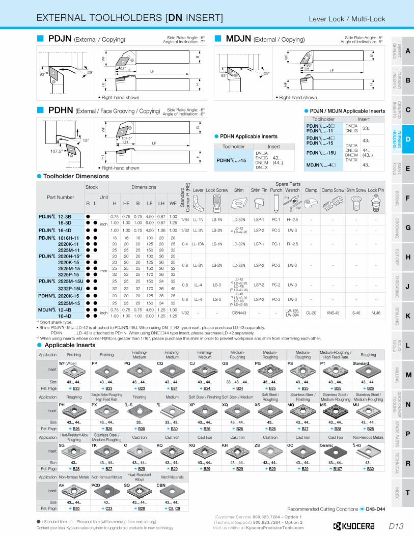
EXTERNAL TOOLHOLDERS [DN INSERT] Lever Lock / Multi-Lock
• Right-hand shown
93°29°
BH
LFLH
WF
93°
HF
• Right-hand shown
� PDJN (External / Copying) � MDJN (External / Copying) Side Rake Angle: -6°Angle of Inclination: -6°
Side Rake Angle: -6°Angle of Inclination: -7°
• Right-hand shown
� PDHN (External / Face Grooving / Copying)Toolholder Insert
PDJN§...-3�PDJN§...-11
DN�ADN�G 33..
PDJN§...-4�PDJN§...-15 DN�A
DN�GDN�MDN�X
43..
PDJN§...-15U 44..(43..)
MDJN§...-4� 43..
� PDJN / MDJN Applicable Inserts
Toolholder Insert
PDHN§...-15
DN�ADN�GDN�MDN�X
43..(44..)
� PDHN Applicable Inserts
Side Rake Angle: -6°Angle of Inclination: -6°
*1 Short shank type.• Shim: PDJN§-15U...LD-42 is attached to PDJN§-15U. When using DN��43 type insert, please purchase LD-43 separately. PDHN ...LD-43 is attached to PDHN. When using DN��44 type Insert, please purchase LD-42 separately.*2 When using inserts whose corner-R(RE) is greater than 1/16", please purchase this shim in order to prevent workpiece and shim from interfering each other.
Part Number
Stock
Unit
DimensionsS
tand
ard
Cor
ner-
R (R
E) Spare Parts
Lever Lock Screw Shim Shim Pin Punch Wrench Clamp Clamp Screw Shim Screw Lock Pin
R L H HF B LF LH WFFH
LW
PDJN§ 12-3B Þ
inch
0.75 0.75 0.75 4.50 0.87 1.001/64 LL-1N LS-1N LD-32N LSP-1 PC-1 FH-2.5 - - - -
16-3D Þ Þ 1.00 1.00 1.00 6.00 0.87 1.25
PDJN§ 16-4D Þ Þ 1.00 1.00 0.75 4.50 1.06 1.00 1/32 LL-3N LS-2N LD-42*2 LD-42-20 LSP-2 PC-2 LW-3 - - - -
PDJN§ 1616H-11 Þ Þ
mm
16 16 16 100 28 200.4 LL-1DN LS-1N LD-32N LSP-1 PC-1 FH-2.5 - - - -2020K-11 Þ Þ 20 20 20 125 28 25
2525M-11 Þ Þ 25 25 25 150 28 32
PDJN§ 2020H-15*1 Þ 20 20 20 100 36 25
0.8 LL-3N LS-2N LD-32N LSP-2 PC-2 LW-3 - - - -2020K-15 Þ Þ 20 20 20 125 36 25
2525M-15 Þ Þ 25 25 25 150 36 32
3225P-15 Þ Þ 32 32 25 170 36 32
PDJN§ 2525M-15U Þ Þ 25 25 25 150 34 320.8 LL-4 LS-3
LD-42*2 LD-42-20
(LD-43)(*2 LD-43-20)
LSP-2 PC-2 LW-3 - - - -3232P-15U Þ Þ 32 32 32 170 36 40
PDHN§ 2020K-15 Þ Þ 20 20 20 125 35 250.8 LL-4 LS-3
LD-43 *2 LD-43-20
(LD-42)(*2 LD-42-20)
LSP-2 PC-2 LW-3 - - - -2525M-15 Þ Þ 25 25 25 150 34 32
MDJN§ 12-4B Þ Þinch
0.75 0.75 0.75 4.50 1.25 1.001/32 - - IDSN443 - - LW-125,
LW-094 CL-20 XNS-48 S-46 NL4616-4D Þ Þ 1.00 1.00 1.00 6.00 1.25 1.25
Application Finishing Finishing Finishing-Medium
Finishing-Medium
Finishing-Medium
Medium-Roughing
Medium-Roughing
Medium-Roughing
Medium-Roughing / High Feed Rate Roughing
Insert
Size 43.., 44.. 43.., 44.. 43.., 44.. 43.., 44.. 43.., 44.. 33.., 43.., 44.. 43.., 44.. 43.., 44.. 43.., 44.. 43.., 44..
Ref. Page � B23 � B23 � B23 � B24 � B24 � B24 � B25 � B25 � B25 � B26
� Applicable Inserts
Recommended Cutting Conditions � D43-D44
WF (Wiper) PP PQ CQ CJ GS PG PS PT Standard
SG TK C KQ KG KH ZS GC Ceramic §-A3
AH PCD SQ CBN
PH PX §-S § XP XQ XS MQ MS MU
� Toolholder Dimensions
D14
D
TUR
NIN
G
HO
LDER
S
(Customer Service) 800.823.7284 - Option 1(Technical Support) 800.823.7284 - Option 2
Visit us online at KyoceraPrecisionTools.comÞ : Standard Item � : Made to Order � : Phaseout Item (will be removed from next catalog)
Contact your local Kyocera sales engineer to upgrade old products to new technology
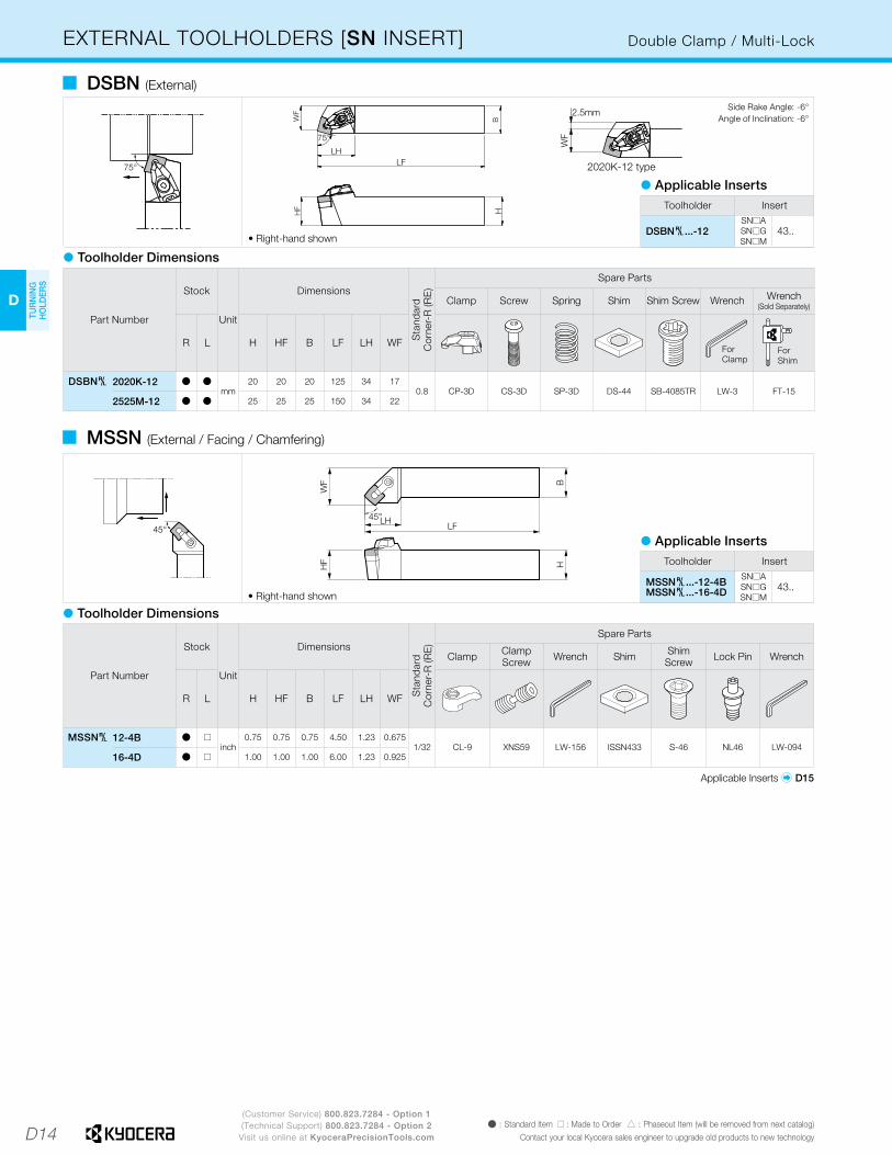
EXTERNAL TOOLHOLDERS [SN INSERT] Double Clamp / Multi-Lock
75°
LHLF
BH
WF
75°
HF
2020K-12 type
WF
2.5mm
• Right-hand shown
� DSBN (External)
45°
WF
HB
HF
LHLF
45°
• Right-hand shown
� Toolholder Dimensions
Part Number
Stock
Unit
Dimensions
Sta
ndar
dC
orne
r-R
(RE
)
Spare Parts
Clamp Screw Spring Shim Shim Screw Wrench Wrench(Sold Separately)
R L H HF B LF LH WFForClamp
ForShim
DSBN§ 2020K-12 Þ Þmm
20 20 20 125 34 170.8 CP-3D CS-3D SP-3D DS-44 SB-4085TR LW-3 FT-15
2525M-12 Þ Þ 25 25 25 150 34 22
Side Rake Angle: -6°Angle of Inclination: -6°
Toolholder Insert
DSBN§...-12SN�A
43..SN�GSN�M
� Applicable Inserts
Toolholder Insert
MSSN§...-12-4BMSSN§...-16-4D
SN�A43..SN�G
SN�M
� Applicable Inserts
� MSSN (External / Facing / Chamfering)
� Toolholder Dimensions
Part Number
Stock
Unit
Dimensions
Sta
ndar
dC
orne
r-R
(RE
)
Spare Parts
Clamp Clamp Screw Wrench Shim Shim
Screw Lock Pin Wrench
R L H HF B LF LH WF
MSSN§ 12-4B Þ �inch
0.75 0.75 0.75 4.50 1.23 0.6751/32 CL-9 XNS59 LW-156 ISSN433 S-46 NL46 LW-094
16-4D Þ � 1.00 1.00 1.00 6.00 1.23 0.925
Applicable Inserts � D15

D15
H
CU
T-OFF
J
THR
EADIN
G
M
MILLIN
G
N
QUICK CHANG
ETO
OLIN
G
R
TECH
NIC
AL
P
SPARE PAR
TS
T
IND
EX
D
TUR
NIN
G
HO
LDER
S
F
BO
RIN
G
B
TUR
NIN
G
INSER
TS
G
GR
OO
VING
C
CB
N/PC
D
INSER
TS
E
SMALL
TOO
LS
K
DR
ILLING
L
SOLID
TOO
LS
A
INSER
T G
RAD
ES
(Customer Service) 800.823.7284 - Option 1(Technical Support) 800.823.7284 - Option 2
Visit us online at KyoceraPrecisionTools.comÞ : Standard Item � : Phaseout Item (will be removed from next catalog)Contact your local Kyocera sales engineer to upgrade old products to new technology
Application Cast Iron Cast Iron /Roughing
Cast Iron /Roughing Cast Iron Cast Iron Cast Iron Cast Iron Hard Materials
Insert
Size 43.. 43.. 43.. 43.. 43.. 43.. 43.. 43..Ref. Page � B34 � B34 � B34 � B34 � B34 � B35 � B109 � C10
Application Finishing-Roughing
Medium-Roughing / Low Cutting Force
Soft Steel / Finishing
Soft Steel / Medium
Soft Steel / Roughing
Stainless Steel / Finishing
Stainless Steel / Medium-Roughing
Heat-Resistant AlloyRoughing
Insert
Size 32.., 43.. 43.. 43.. 43.. 43.. 43.. 43.. 43..
Ref. Page � B35 � B35 � B33 � B33 � B33 � B34 � B34 � B34
EXTERNAL TOOLHOLDERS [SN INSERT] Lever Lock
• Right-hand shown
• Right-hand shown
• Right-hand shown
� PSBN (External)
� PSKN (Facing)
� PSSN (External / Facing / Chamfering)
Side Rake Angle: -6°Angle of Inclination: -6°
Side Rake Angle: -6°Angle of Inclination: -6°
Side Rake Angle: -8°Angle of Inclination: 0°
� PSDN (External / Chamfering)
Back Rake Angle: -8.5°
Part Number
Stock
Unit
DimensionsS
tand
ard
Cor
ner-
R (R
E) Spare Parts
Lever Lock Screw Shim Shim Pin Punch Wrench
R N L H HF B LF LH WF WFS
FH
LW
PSBN§ 1616H-09 Þ Þ
mm
16 16 16 100 21.0 13 - 0.8 LL-1N LS-1N LS-32 LSP-1 PC-1 FH-2.5
2020K-12 Þ Þ 20 20 20 125 27.0 17 -0.8 LL-2N LS-2N LS-42 LSP-2 PC-2 LW-3
2525M-12 Þ Þ 25 25 25 150 24.0 22 -
PSKN§ 1616H-09 Þ Þ 16 16 16 100 19.0 20 - 0.8 LL-1N LS-1N LS-32 LSP-1 PC-1 FH-2.5
2020K-12 Þ Þ 20 20 20 125 22.5 25 -0.8 LL-2N LS-2N LS-42 LSP-2 PC-2 LW-3
2525M-12 Þ Þ 25 25 25 150 22.5 32 -
PSSN§ 1616H-09 Þ Þ 16 16 16 100 22 20 13.6 0.8 LL-1N LS-1N LS-32 LSP-1 PC-1 FH-2.5
2020K-12 Þ Þ 20 20 20 125 29 25 16.40.8 LL-2N LS-2N LS-42 LSP-2 PC-2 LW-3
2525M-12 Þ Þ 25 25 25 150 29 32 23.4
PSDNN 1616H-09 Þ 16 16 16 100 21 8 - 0.8 LL-1N LS-1N LS-32 LSP-1 PC-1 FH-2.5
2020K-12 Þ 20 20 20 125 30 10 -0.8 LL-2N LS-2N LS-42 LSP-2 PC-2 LW-3
2525M-12 Þ 25 25 25 150 30 12.5 -
� Toolholder Dimensions
• PSKN§: Left-hand Insert for Right-hand Toolholder, Right-hand Insert for Left-hand Toolholder.• PSSN§: For External Turning, Right-hand Insert for Right-hand Toolholder, Left-hand Insert for Left-hand Toolholder For Facing, Left-hand Insert for Right-hand Toolholder, Right-hand Insert for Left-hand Toolholder
Application Finishing-Medium Medium-Roughing Medium-Roughing Medium-RoughingMedium-Roughing /
High Feed Rate Roughing RoughingSingle Sided
Roughing High Feed
Insert
Size 43.. 43.. 43.. 43.. 43.. 32.., 43.. 43.. 43..
Ref. Page � B32 � B32 � B32 � B32 � B32 � B32 � B33 � B33
� Applicable Inserts
Recommended Cutting Conditions � D43-D44
PQ PG PS HS PT Standard PH PX
Toolholder Insert
PSBN§…-09
SN�G 32..PSKN§…-09
PSSN§…-09
PSDNN…-09
PSBN§…-12
SN�ASN�GSN�M
43..PSKN§…-12
PSSN§…-12
PSDNN…-12
C KG KH ZS GC Without Chipbreaker Ceramic CBN
§-� §-25R XP XQ XS MQ MS SG
D16
D
TUR
NIN
G
HO
LDER
S
(Customer Service) 800.823.7284 - Option 1(Technical Support) 800.823.7284 - Option 2
Visit us online at KyoceraPrecisionTools.comÞ : Standard Item � : Phaseout Item (will be removed from next catalog)
Contact your local Kyocera sales engineer to upgrade old products to new technology
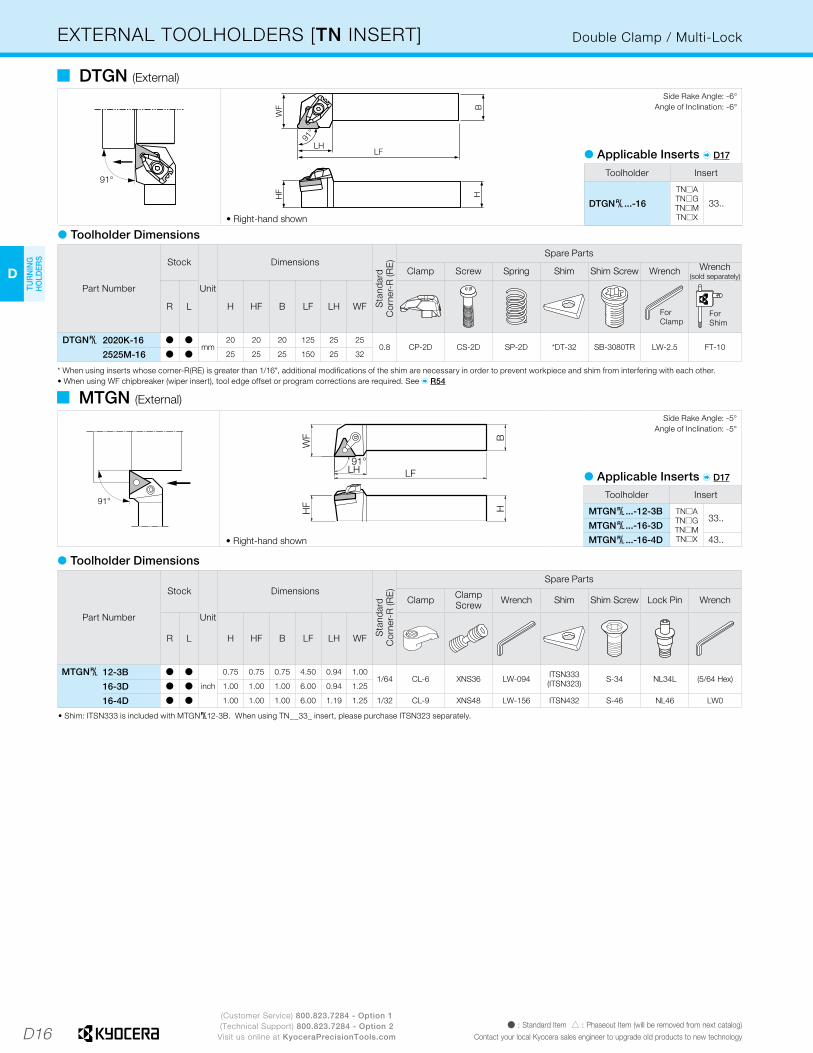
EXTERNAL TOOLHOLDERS [TN INSERT] Double Clamp / Multi-Lock
� Toolholder Dimensions
91°
HF H
WF B
LFLH
91°
• Right-hand shown
� DTGN (External)
Part Number
Stock
Unit
Dimensions
Sta
ndar
dC
orne
r-R
(RE
)
Spare Parts
Clamp Screw Spring Shim Shim Screw Wrench Wrench(sold separately)
R L H HF B LF LH WFForClamp
ForShim
DTGN§ 2020K-16 Þ Þmm
20 20 20 125 25 250.8 CP-2D CS-2D SP-2D *DT-32 SB-3080TR LW-2.5 FT-10
2525M-16 Þ Þ 25 25 25 150 25 32
* When using inserts whose corner-R(RE) is greater than 1/16", additional modifications of the shim are necessary in order to prevent workpiece and shim from interfering with each other.• When using WF chipbreaker (wiper insert), tool edge offset or program corrections are required. See � R54
Side Rake Angle: -6°Angle of Inclination: -6°
Toolholder Insert
DTGN§...-16
TN�ATN�GTN�MTN�X
33..
� Applicable Inserts � D17
� Toolholder Dimensions
HF
WF
91°LH LF
HB
• Right-hand shown
� MTGN (External)
Part Number
Stock
Unit
Dimensions
Sta
ndar
dC
orne
r-R
(RE
)
Spare Parts
Clamp Clamp Screw Wrench Shim Shim Screw Lock Pin Wrench
R L H HF B LF LH WF
MTGN§ 12-3B Þ Þ
inch
0.75 0.75 0.75 4.50 0.94 1.001/64 CL-6 XNS36 LW-094 ITSN333
(ITSN323) S-34 NL34L (5/64 Hex)16-3D Þ Þ 1.00 1.00 1.00 6.00 0.94 1.25
16-4D Þ Þ 1.00 1.00 1.00 6.00 1.19 1.25 1/32 CL-9 XNS48 LW-156 ITSN432 S-46 NL46 LW0
• Shim: ITSN333 is included with MTGN§12-3B. When using TN__33_ insert, please purchase ITSN323 separately.
Side Rake Angle: -5°Angle of Inclination: -5°
Toolholder Insert
MTGN§...-12-3B TN�ATN�GTN�MTN�X
33..MTGN§...-16-3D
MTGN§...-16-4D 43..
� Applicable Inserts � D17
D17
H
CU
T-OFF
J
THR
EADIN
G
M
MILLIN
G
N
QUICK CHANG
ETO
OLIN
G
R
TECH
NIC
AL
P
SPARE PAR
TS
T
IND
EX
D
TUR
NIN
G
HO
LDER
S
F
BO
RIN
G
B
TUR
NIN
G
INSER
TS
G
GR
OO
VING
C
CB
N/PC
D
INSER
TS
E
SMALL
TOO
LS
K
DR
ILLING
L
SOLID
TOO
LS
A
INSER
T G
RAD
ES
(Customer Service) 800.823.7284 - Option 1(Technical Support) 800.823.7284 - Option 2
Visit us online at KyoceraPrecisionTools.comÞ : Standard Item � : Phaseout Item (will be removed from next catalog)Contact your local Kyocera sales engineer to upgrade old products to new technology
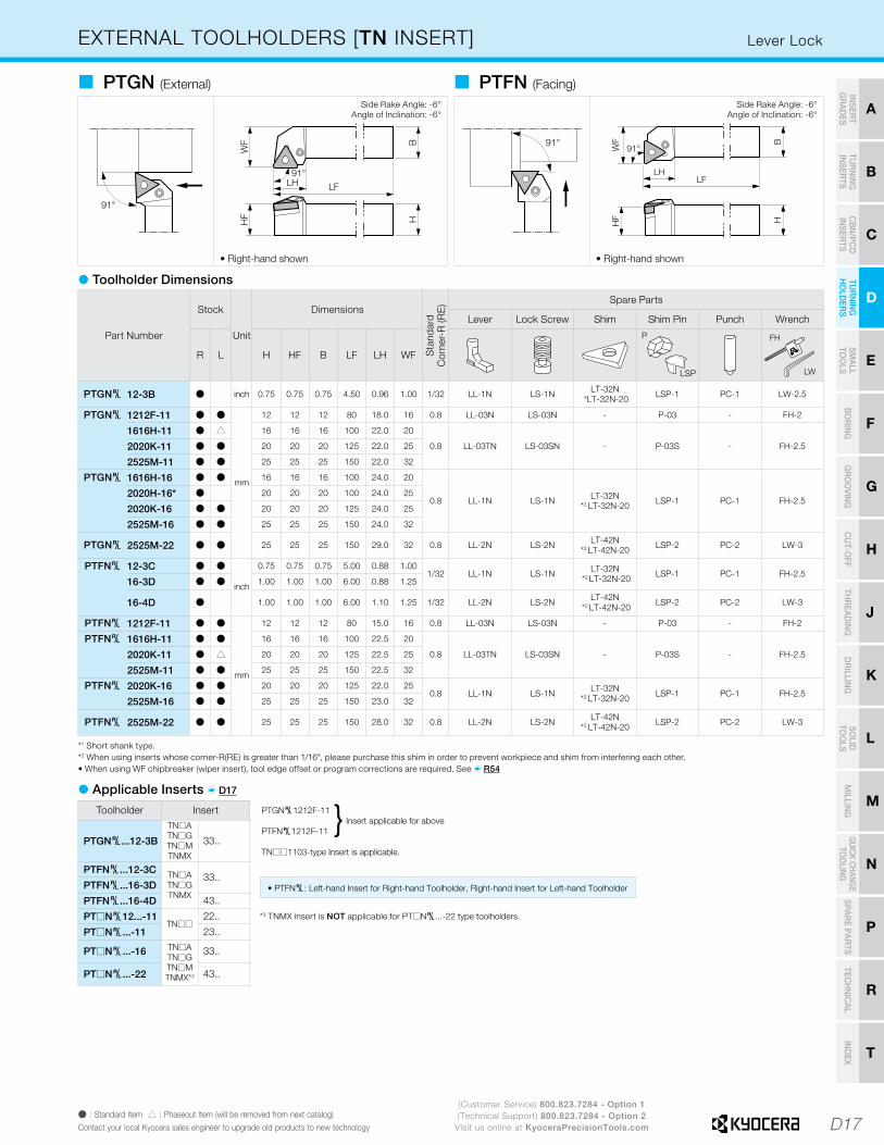
EXTERNAL TOOLHOLDERS [TN INSERT]
� Toolholder Dimensions
Part Number
Stock
Unit
Dimensions
Sta
ndar
dC
orne
r-R
(RE
) Spare Parts
Lever Lock Screw Shim Shim Pin Punch Wrench
R L H HF B LF LH WF
LSP
P FH
LW
PTGN§ 12-3B Þ inch 0.75 0.75 0.75 4.50 0.96 1.00 1/32 LL-1N LS-1N LT-32N *LT-32N-20 LSP-1 PC-1 LW-2.5
PTGN§ 1212F-11 Þ Þ
mm
12 12 12 80 18.0 16 0.8 LL-03N LS-03N - P-03 - FH-2
1616H-11 Þ � 16 16 16 100 22.0 20
0.8 LL-03TN LS-03SN - P-03S - FH-2.52020K-11 Þ Þ 20 20 20 125 22.0 25
2525M-11 Þ Þ 25 25 25 150 22.0 32
PTGN§ 1616H-16 Þ Þ 16 16 16 100 24.0 20
0.8 LL-1N LS-1N LT-32N*2 LT-32N-20 LSP-1 PC-1 FH-2.5
2020H-16* Þ 20 20 20 100 24.0 25
2020K-16 Þ Þ 20 20 20 125 24.0 25
2525M-16 Þ Þ 25 25 25 150 24.0 32
PTGN§ 2525M-22 Þ Þ 25 25 25 150 29.0 32 0.8 LL-2N LS-2N LT-42N*2 LT-42N-20 LSP-2 PC-2 LW-3
PTFN§ 12-3C Þ Þ
inch
0.75 0.75 0.75 5.00 0.88 1.001/32 LL-1N LS-1N LT-32N
*2 LT-32N-20 LSP-1 PC-1 FH-2.516-3D Þ Þ 1.00 1.00 1.00 6.00 0.88 1.25
16-4D Þ 1.00 1.00 1.00 6.00 1.10 1.25 1/32 LL-2N LS-2N LT-42N *2 LT-42N-20 LSP-2 PC-2 LW-3
PTFN§ 1212F-11 Þ Þ
mm
12 12 12 80 15.0 16 0.8 LL-03N LS-03N - P-03 - FH-2
PTFN§ 1616H-11 Þ Þ 16 16 16 100 22.5 20
0.8 LL-03TN LS-03SN - P-03S - FH-2.52020K-11 Þ � 20 20 20 125 22.5 25
2525M-11 Þ Þ 25 25 25 150 22.5 32
PTFN§ 2020K-16 Þ Þ 20 20 20 125 22.0 250.8 LL-1N LS-1N LT-32N
*2 LT-32N-20 LSP-1 PC-1 FH-2.52525M-16 Þ Þ 25 25 25 150 23.0 32
PTFN§ 2525M-22 Þ Þ 25 25 25 150 28.0 32 0.8 LL-2N LS-2N LT-42N*2 LT-42N-20 LSP-2 PC-2 LW-3
� PTGN (External)
• Right-hand shown
Side Rake Angle: -6°Angle of Inclination: -6°
� PTFN (Facing)
• Right-hand shown
Side Rake Angle: -6°Angle of Inclination: -6°
*1 Short shank type.*2 When using inserts whose corner-R(RE) is greater than 1/16", please purchase this shim in order to prevent workpiece and shim from interfering each other.• When using WF chipbreaker (wiper insert), tool edge offset or program corrections are required. See � R54
*3 TNMX insert is NOT applicable for PT�N§...-22 type toolholders.
Toolholder Insert
PTGN§...12-3B
TN�ATN�GTN�MTNMX
33..
PTFN§...12-3C TN�ATN�GTNMX
33..PTFN§...16-3D
PTFN§...16-4D 43..
PT�N§12...-11TN��
22..
PT�N§...-11 23..
PT�N§...-16 TN�ATN�GTN�MTNMX*3
33..
PT�N§...-22 43..
� Applicable Inserts � D17
PTGN§1212F-11 Insert applicable for above
PTFN§1212F-11
TN��1103-type Insert is applicable.
}
• PTFN§: Left-hand Insert for Right-hand Toolholder, Right-hand Insert for Left-hand Toolholder
Lever Lock

D18
D
TUR
NIN
G
HO
LDER
S
(Customer Service) 800.823.7284 - Option 1(Technical Support) 800.823.7284 - Option 2
Visit us online at KyoceraPrecisionTools.comÞ : Standard Item � : Phaseout Item (will be removed from next catalog)
Contact your local Kyocera sales engineer to upgrade old products to new technology
EXTERNAL TOOLHOLDERS [TN INSERT] Wedge Lock
• Right-hand shown
� WTJN (External / Copying)Side Rake Angle: -6°
Angle of Inclination: -6°
• Right-hand shown
� WTKN (External / Facing / Copying)
• Right-hand shown
� WTEN (External / Chamfering)
WTJN§2020K type:Shim Nut sticks outas shown below.
Side Rake Angle: -6°Angle of Inclination: -6°
WTKN§2020K type:Shim Nut sticks out as shown below.
Back Rake Angle: -8.5°
WTENN2020K type:Shim Nut sticks out as shown below.
Part Number
Stock
Unit
Dimensions
Sta
ndar
dC
orne
r-R
(RE
) Spare Parts
Clamp Set Shim Shim Pin Shim Nut Wrench Spacer
R N L H HF B LF LH WF
WTJN§ 12-3C Þ Þinch
0.75 0.75 0.75 5.00 1.26 1.001/32 WCS-1N WTN-33
*WTN-33-20 WP-1S WN-1 LW-3 WSP-116-3D Þ Þ 1.00 1.00 1.00 6.00 1.26 1.25
WTJN§ 2020K-16N Þ Þmm
20 20 20 125 32 25.00.8 WCS-1N WTN-33
*WTN-33-20 WP-1S WN-1 LW-3 WSP-12525M-16N Þ Þ 25 25 25 150 32 32.0
WTKN§ 12-3C Þ Þ inch 0.75 0.75 0.75 5.00 1.26 1.00 1/32 WCS-1N WTN-33 *WTN-33-20 WP-1S WN-1 LW-3 WSP-1
WTKN§ 2020K-16N Þ Þmm
20 20 20 125 32 25.00.8 WCS-1N WTN-33
*WTN-33-20 WP-1S WN-1 LW-3 WSP-12525M-16N Þ Þ 25 25 25 150 32 32.0
WTENN 2020K-16N Þmm
20 20 20 125 32 10.00.8 WCS-1N WTN-33
*WTN-33-20 WP-1S WN-1 LW-3 WSP-12525M-16N Þ 25 25 25 150 32 12.5
� Toolholder Dimensions
* When using inserts whose corner-R (RE) is greater than 1/16", please purchase a shim (WTN-33-20) with * mark and use it in order to prevent workpiece and shim from interfering with each other.
� Applicable Inserts � D19
Toolholder Insert
WTJN§...12-3C
TN�ATN�GTN�M
33..
WTJN§...16-3D
WTJN§...-16N
WTKN§...12-3C
WTKN§...16-3D
WTKN§...-16N
Toolholder Insert
WTENN...-16NTN�ATN�GTN�M
33..
D19
H
CU
T-OFF
J
THR
EADIN
G
M
MILLIN
G
N
QUICK CHANG
ETO
OLIN
G
R
TECH
NIC
AL
P
SPARE PAR
TS
T
IND
EX
D
TUR
NIN
G
HO
LDER
S
F
BO
RIN
G
B
TUR
NIN
G
INSER
TS
G
GR
OO
VING
C
CB
N/PC
D
INSER
TS
E
SMALL
TOO
LS
K
DR
ILLING
L
SOLID
TOO
LS
A
INSER
T G
RAD
ES
800.823.7284Visit us online at KyoceraPrecisionTools.com
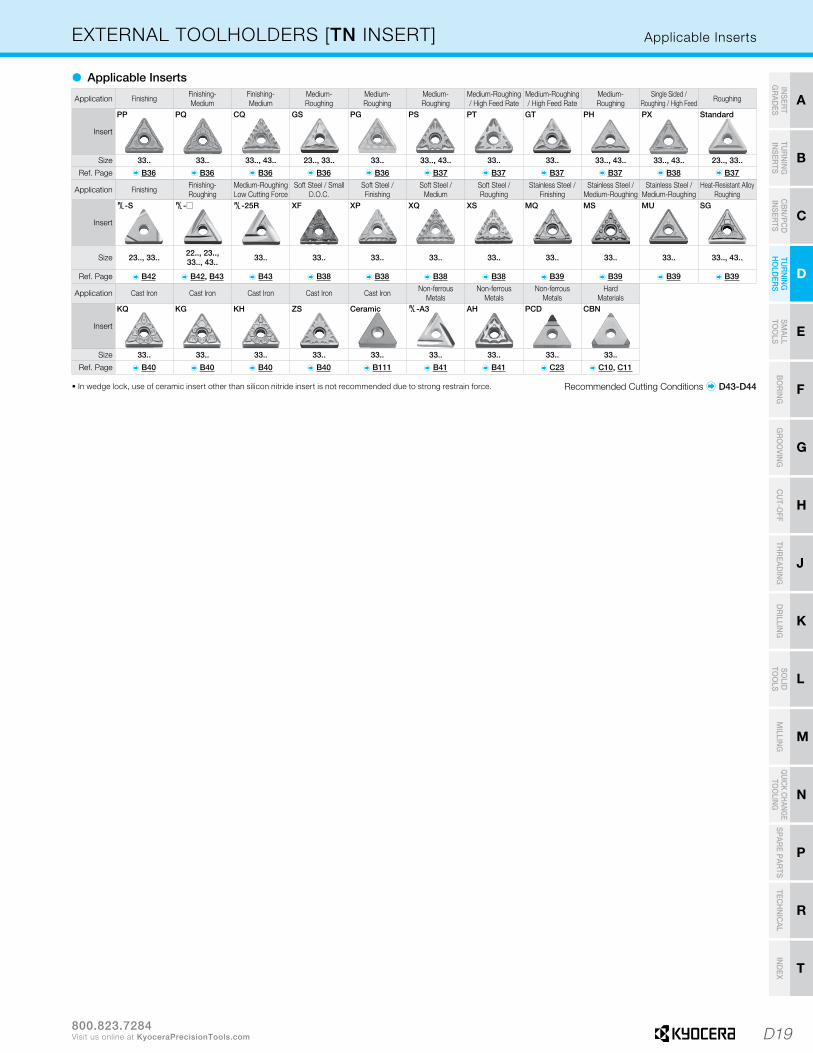
Application Finishing Finishing-Roughing
Medium-Roughing Low Cutting Force
Soft Steel / Small D.O.C.
Soft Steel /Finishing
Soft Steel /Medium
Soft Steel /Roughing
Stainless Steel / Finishing
Stainless Steel / Medium-Roughing
Stainless Steel / Medium-Roughing
Heat-Resistant AlloyRoughing
Insert
Size 23.., 33.. 22.., 23..,33.., 43.. 33.. 33.. 33.. 33.. 33.. 33.. 33.. 33.. 33.., 43..
Ref. Page � B42 � B42, B43 � B43 � B38 � B38 � B38 � B38 � B39 � B39 � B39 � B39
EXTERNAL TOOLHOLDERS [TN INSERT] Applicable Inserts
Application Cast Iron Cast Iron Cast Iron Cast Iron Cast Iron Non-ferrousMetals
Non-ferrousMetals
Non-ferrousMetals
HardMaterials
Insert
Size 33.. 33.. 33.. 33.. 33.. 33.. 33.. 33.. 33..
Ref. Page � B40 � B40 � B40 � B40 � B111 � B41 � B41 � C23 � C10, C11
Application Finishing Finishing-Medium
Finishing-Medium
Medium-Roughing
Medium-Roughing
Medium-Roughing
Medium-Roughing / High Feed Rate
Medium-Roughing / High Feed Rate
Medium-Roughing
Single Sided / Roughing / High Feed Roughing
Insert
Size 33.. 33.. 33.., 43.. 23.., 33.. 33.. 33.., 43.. 33.. 33.. 33.., 43.. 33.., 43.. 23.., 33..
Ref. Page � B36 � B36 � B36 � B36 � B36 � B37 � B37 � B37 � B37 � B38 � B37
� Applicable Inserts
Recommended Cutting Conditions � D43-D44
PP PQ CQ GS PG PS PT GT PH PX Standard
§-S §-� §-25R XF XP XQ XS MQ MS MU SG
KQ KG KH ZS Ceramic §-A3 AH PCD CBN
• In wedge lock, use of ceramic insert other than silicon nitride insert is not recommended due to strong restrain force.
D20
D
TUR
NIN
G
HO
LDER
S
(Customer Service) 800.823.7284 - Option 1(Technical Support) 800.823.7284 - Option 2
Visit us online at KyoceraPrecisionTools.comÞ : Standard Item � : Phaseout Item (will be removed from next catalog)
Contact your local Kyocera sales engineer to upgrade old products to new technology
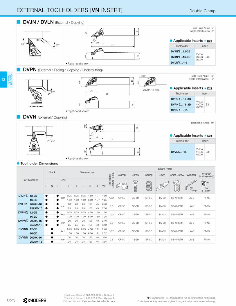
EXTERNAL TOOLHOLDERS [VN INSERT] Double Clamp
95° 47°
HF H
B
LFLH
95°
WF
• Right-hand shown
� DVJN / DVLN (External / Copying)Side Rake Angle: -6°
Angle of Inclination: -9°
25°
H
LFLH
B
WF
2020K-16 type
WF
0.197”
HF
• Right-hand shown
� DVPN (External / Facing / Copying / Undercutting)
70°B
H
WF
LFLH
72.5°
HF
• Right-hand shown
� DVVN (External / Copying)
Side Rake Angle: -13°Angle of Inclination: -10°
Back Rake Angle: -11°
� Toolholder Dimensions
Toolholder Insert
DVJN§...12-3BVN�AVN�GVN�M
33..DVJN§...16-3D
DVLN§...-16
� Applicable Inserts � D21
Toolholder Insert
DVPN§...12-3BVN�AVN�GVN�M
33..DVPN§...16-3D
DVPN§...-16
� Applicable Inserts � D21
Toolholder Insert
DVVNN...-16VN�AVN�GVN�M
33..
� Applicable Inserts � D21
Part Number
Stock
Unit
Dimensions
Sta
ndar
dC
orne
r-R
(RE
)
Spare Parts
Clamp Screw Spring Shim Shim Screw Wrench Wrench(sold separately)
R N L H HF B LF LH WFForClamp
ForShim
DVJN§ 12-3B Þ Þinch
0.75 0.75 0.75 4.50 1.77 1.001/32 CP-5D CS-5D SP-5D DV-33 SB-4085TR LW-3 FT-15
16-3D Þ Þ 1.00 1.00 1.00 6.00 1.77 1.25
DVLN§ 2020K-16 Þ Þmm
20 20 20 125 45 25.00.8 CP-5D CS-5D SP-5D DV-33 SB-4085TR LW-3 FT-15
2525M-16 Þ Þ 25 25 25 150 45 32.0
DVPN§ 12-3B Þ Þinch
0.75 0.75 0.75 4.50 1.58 1.001/32 CP-5D CS-5D SP-5D DV-33 SB-4085TR LW-3 FT-15
16-3D Þ Þ 1.00 1.00 1.00 6.00 1.58 1.25
DVPN§ 2020K-16 Þ Þmm
20 20 20 125 40 27.00.8 CP-5D CS-5D SP-5D DV-33 SB-4085TR LW-3 FT-15
2525M-16 Þ Þ 25 25 25 150 40 32.0
DVVNN 12-3B Þinch
0.75 0.75 0.75 4.50 1.81 0.401/32 CP-5D CS-5D SP-5D DV-33 SB-4085TR LW-3 FT-15
16-3D Þ 1.00 1.00 1.00 6.00 1.81 0.52
DVVNN 2020K-16 Þmm
20 20 20 125 46 10.00.8 CP-5D CS-5D SP-5D DV-33 SB-4085TR LW-3 FT-15
2525M-16 Þ 25 25 25 150 46 12.5

D21
H
CU
T-OFF
J
THR
EADIN
G
M
MILLIN
G
N
QUICK CHANG
ETO
OLIN
G
R
TECH
NIC
AL
P
SPARE PAR
TS
T
IND
EX
D
TUR
NIN
G
HO
LDER
S
F
BO
RIN
G
B
TUR
NIN
G
INSER
TS
G
GR
OO
VING
C
CB
N/PC
D
INSER
TS
E
SMALL
TOO
LS
K
DR
ILLING
L
SOLID
TOO
LS
A
INSER
T G
RAD
ES
(Customer Service) 800.823.7284 - Option 1(Technical Support) 800.823.7284 - Option 2
Visit us online at KyoceraPrecisionTools.comÞ : Standard Item � : Phaseout Item (will be removed from next catalog)Contact your local Kyocera sales engineer to upgrade old products to new technology
Application Stainless Steel / Medium-Roughing
Heat-Resistant AlloyRoughing
Cast Iron Cast Iron Cast Iron Cast Iron Non-ferrous Metals Hard Materials
Insert
Size 33.. 33.. 33.. 33.. 33.. 33.. 33.. 33..
Ref. Page � B45 � B45 � B45 � B45 � B45 � B112 � C23 � C12
EXTERNAL TOOLHOLDERS [VN INSERT] Multi-Lock
52°
93° BH
WF
LFLH93°
52°
HF
• Right-hand shown • Right-hand shown
� MVJN (External / Copying) � MVLN (External / Copying)
Side Rake Angle: -6°Angle of Inclination: -9°
Side Rake Angle: -6°Angle of Inclination: -9°
� MVVN (External / Copying)
Back Rake Angle: -11°
Part Number
Stock
Unit
Dimensions
Sta
ndar
dC
orne
r-R
(RE
)Spare Parts
ClampSet Wrench Shim Shim
ScrewLockPin Wrench Clamp Clamp
Screw
R N L H HF B LF LH WF
FH
Hex
FH
LX/LW
MVJN§ 12-3B Þ Þinch
0.75 0.75 0.75 4.5 1.69 1.001/64 - (5/64 hex) IVSN322 S-34 NL34L LX-156 CL-30 XNS48
16-3C Þ Þ 1.00 1.00 1.00 5.0 1.69 1.25
MVLN§ 2020K-16 Þ Þmm
20 20 20 125 38 25.00.8 CPS-5§ FH-2.5 MVN-32 - TS-3S FH-2 - -
2525M-16 Þ Þ 25 25 25 150 38 32.0
MVVNN 12-3B Þinch
0.75 0.75 0.75 4.50 1.67 0.3751/32 CPS-5R (5/64 Hex) IVNS322 - NL34L LW-156 CL-12 XNS48
16-3D Þ 1.00 1.00 1.00 6.00 1.67 0.500
MVVNN 2020K-16 Þmm
20 20 20 125 39 10.00.8 CPS-5R FH-2.5 MVN-32 - TS-3S FH-2 - -
2525M-16 Þ 25 25 25 150 39 12.5
� Toolholder Dimensions
Recommended Cutting Conditions � D43-D44
Application Finishing Finishing-Medium
Finishing-Medium
Finishing-Medium Medium Roughing Finishing-
MediumStainless Steel /
FinishingStainless Steel /
Medium-Roughing
Insert
Size 33.. 33.. 33.. 33.. 33.. 33.. 33.. 33.. 33..
Ref. Page � B44 � B44 � B44 � B44 � B44 � B44 � B45 � B45 � B45
PP § -VC VF PQ TN-V Standard § MQ MS
MU SG KG KH Without Chipbreaker Ceramic PCD CBN
• Clamp Set: CPS-5R for Right-hand Toolholder, CPS-5L for Left-hand Toolholder.
� Rotation Directions of the Clamp Set
Clamp set: (CPS-5R) has Right-hand thread.When clamping the insert, turn the screw in the arrow direction (clockwise).When removing the insert, turn the screw away from the arrow (counterclockwise).
Clamp set: (CPS-5L) has Left-hand thread.When clamping the insert, turn the screw in the arrow direction (counterclockwise).When removing the insert, turn the screw away from the arrow (clockwise).
MVLNR type(Right-hand Toolholder)
MVLNL type(Left-hand Toolholder)
MVVNN type(Neutral)
Toolholder Insert
MVJN§...12-3B
VN�AVN�GVN�M
33..
MVJN§...16-3C
MVLN§...-16
MVVNN...12-3B
MVVNN...16-3D
MVVNN...-16
� Applicable Inserts
D22
D
TUR
NIN
G
HO
LDER
S
(Customer Service) 800.823.7284 - Option 1(Technical Support) 800.823.7284 - Option 2
Visit us online at KyoceraPrecisionTools.comÞ : Standard Item � : Phaseout Item (will be removed from next catalog)
Contact your local Kyocera sales engineer to upgrade old products to new technology
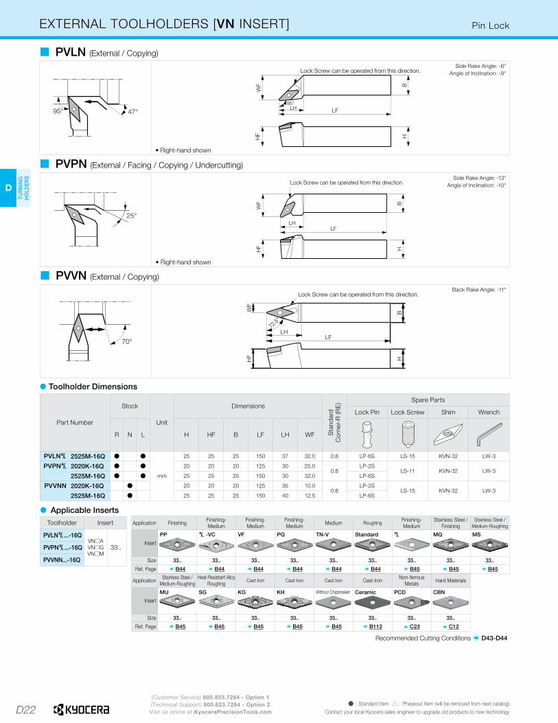
EXTERNAL TOOLHOLDERS [VN INSERT] Pin Lock
• Right-hand shown
� PVLN (External / Copying)Side Rake Angle: -6°
Angle of Inclination: -9°
• Right-hand shown
� PVPN (External / Facing / Copying / Undercutting)
� PVVN (External / Copying)
Side Rake Angle: -13°Angle of Inclination: -10°
Back Rake Angle: -11°
Part Number
Stock
Unit
Dimensions
Sta
ndar
dC
orne
r-R
(RE
) Spare Parts
Lock Pin Lock Screw Shim Wrench
R N L H HF B LF LH WF
PVLN§ 2525M-16Q Þ Þ
mm
25 25 25 150 37 32.0 0.8 LP-6S LS-15 KVN-32 LW-3
PVPN§ 2020K-16Q Þ Þ 20 20 20 125 30 25.00.8
LP-2SLS-11 KVN-32 LW-3
2525M-16Q Þ Þ 25 25 25 150 30 32.0 LP-6S
PVVNN 2020K-16Q Þ 20 20 20 125 35 10.00.8
LP-2SLS-15 KVN-32 LW-3
2525M-16Q Þ 25 25 25 150 40 12.5 LP-6S
� Toolholder Dimensions
� Applicable InsertsToolholder Insert
PVLN§...-16QVN�AVN�GVN�M
33..PVPN§...-16Q
PVVNN...-16Q
Recommended Cutting Conditions � D43-D44
Application Stainless Steel / Medium-Roughing
Heat-Resistant AlloyRoughing
Cast Iron Cast Iron Cast Iron Cast Iron Non-ferrous Metals Hard Materials
Insert
Size 33.. 33.. 33.. 33.. 33.. 33.. 33.. 33..
Ref. Page � B45 � B45 � B45 � B45 � B45 � B112 � C23 � C12
Application Finishing Finishing-Medium
Finishing-Medium
Finishing-Medium Medium Roughing Finishing-
MediumStainless Steel /
FinishingStainless Steel /
Medium-Roughing
Insert
Size 33.. 33.. 33.. 33.. 33.. 33.. 33.. 33.. 33..
Ref. Page � B44 � B44 � B44 � B44 � B44 � B44 � B45 � B45 � B45
PP § -VC VF PQ TN-V Standard § MQ MS
MU SG KG KH Without Chipbreaker Ceramic PCD CBN
D23
H
CU
T-OFF
J
THR
EADIN
G
M
MILLIN
G
N
QUICK CHANG
ETO
OLIN
G
R
TECH
NIC
AL
P
SPARE PAR
TS
T
IND
EX
D
TUR
NIN
G
HO
LDER
S
F
BO
RIN
G
B
TUR
NIN
G
INSER
TS
G
GR
OO
VING
C
CB
N/PC
D
INSER
TS
E
SMALL
TOO
LS
K
DR
ILLING
L
SOLID
TOO
LS
A
INSER
T G
RAD
ES
(Customer Service) 800.823.7284 - Option 1(Technical Support) 800.823.7284 - Option 2
Visit us online at KyoceraPrecisionTools.comÞ : Standard Item � : Phaseout Item (will be removed from next catalog)Contact your local Kyocera sales engineer to upgrade old products to new technology
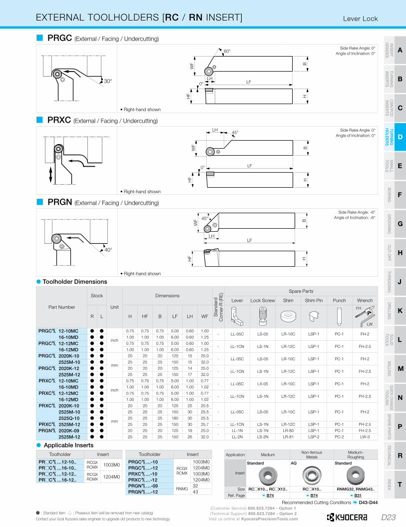
EXTERNAL TOOLHOLDERS [RC / RN INSERT] Lever Lock
30°
• Right-hand shown
� PRGC (External / Facing / Undercutting)Side Rake Angle: 0°
Angle of Inclination: 0°
• Right-hand shown
� PRXC (External / Facing / Undercutting)
40°
• Right-hand shown
� PRGN (External / Facing / Undercutting)
Side Rake Angle: 0°Angle of Inclination: 0°
Side Rake Angle: -6°Angle of Inclination: -6°
� Applicable Inserts
Recommended Cutting Conditions � D43-D44
Application Medium Non-ferrousMetals
Medium-Roughing
Insert
Size RC�X10.., RC�X12.. RC�X10.. RNMG32, RNMG43..
Ref. Page � B74 � B74 � B31
Standard AQ Standard
Toolholder Insert
PR�C§…12-10.. RCGXRCMX 1003M0
PR�C§…16-10..PR�C§…12-12.. RCGX
RCMX 1204M0PR�C§…16-12..
Toolholder Insert
PRGC§…-10RCGXRCMX
1003M0PRGC§…-12 1204M0PRXC§…-10 1003M0PRXC§…-12 1204M0PRGN§…-09
RNMG32
PRGN§…-12 43
� Toolholder Dimensions
Part Number
Stock
Unit
Dimensions
Sta
ndar
dC
orne
r-R
(RE
) Spare Parts
Lever Lock Screw Shim Shim Pin Punch Wrench
R L H HF B LF LH WF
FH
LW
PRGC§ 12-10MC Þ Þ
inch
0.75 0.75 0.75 5.00 0.60 1.00- LL-05C LS-05 LR-10C LSP-1 PC-1 FH-2
16-10MD Þ Þ 1.00 1.00 1.00 6.00 0.60 1.25
PRGC§ 12-12MC Þ Þ 0.75 0.75 0.75 5.00 0.60 1.00- LL-1CN LS-1N LR-12C LSP-1 PC-1 FH-2.5
16-12MD Þ Þ 1.00 1.00 1.00 6.00 0.60 1.25
PRGC§ 2020K-10 Þ Þ
mm
20 20 20 125 15 25.0- LL-05C LS-05 LR-10C LSP-1 PC-1 FH-2
2525M-10 Þ Þ 25 25 25 150 15 32.0
PRGC§ 2020K-12 Þ Þ 20 20 20 125 14 25.0- LL-1CN LS-1N LR-12C LSP-1 PC-1 FH-2.5
2525M-12 Þ Þ 25 25 25 150 17 32.0
PRXC§ 12-10MC Þ Þ
inch
0.75 0.75 0.75 5.00 1.00 0.77- LL-05C LX-05 LR-10C LSP-1 PC-1 FH-2
16-10MD Þ Þ 1.00 1.00 1.00 6.00 1.00 1.02
PRXC§ 12-12MC Þ Þ 0.75 0.75 0.75 5.00 1.00 0.77- LL-1CN LS-1N LR-12C LSP-1 PC-1 FH-2.5
16-12MD Þ Þ 1.00 1.00 1.00 6.00 1.00 1.02
PRXC§ 2020K-10 Þ Þ
mm
20 20 20 125 25 20.5
- LL-05C LS-05 LR-10C LSP-1 PC-1 FH-22525M-10 Þ Þ 25 25 25 150 30 25.5
2525Q-10 Þ Þ 25 25 25 180 30 25.5
PRXC§ 2525M-12 Þ Þ 25 25 25 150 30 25.7 - LL-1CN LS-1N LR-12C LSP-1 PC-1 FH-2.5
PRGN§ 2020K-09 Þ Þ 20 20 20 125 19 25.0-
LL-1N LS-1N LR-80 LSP-1 PC-1 FH-2.5
2525M-12 Þ Þ 25 25 25 150 26 32.0 LL-2N LS-2N LR-81 LSP-2 PC-2 LW-3

D24
D
TUR
NIN
G
HO
LDER
S
(Customer Service) 800.823.7284 - Option 1(Technical Support) 800.823.7284 - Option 2
Visit us online at KyoceraPrecisionTools.comÞ : Standard Item � : Made to Order � : Phaseout Item (will be removed from next catalog)
Contact your local Kyocera sales engineer to upgrade old products to new technology
Double Clamp / Multi-LockEXTERNAL TOOLHOLDERS [WN INSERT]
95°
HF
H
95°
WF
LFLH
B
• Right-hand shown
� DWLN (External / Facing)Side Rake Angle: -6°
Angle of Inclination: -6°
Toolholder Insert
DWLN§...12-3B WN�GWN�M 33..
DWLN§...16-3D
DWLN§...12-4BWN�AWN�GWN�M
43..DWLN§...16-4B
DWLN§...-08
� Applicable Inserts � D25
� Toolholder Dimensions
Part Number
Stock
Unit
Dimensions
Sta
ndar
dC
orne
r-R
(RE
)
Spare Parts
Clamp Screw Spring Shim Shim Screw Wrench Wrench(sold separately)
R L H HF B LF LH WF
DWLN§ 12-3B Þ Þ
inch
0.75 0.75 0.75 4.50 1.06 1.00
1/32
CP-2D CS-2D SP-2D DW-32 SB-3080TR LW-2.5 FT-1016-3D Þ Þ 1.00 1.00 1.00 6.00 1.06 1.25
DWLN§ 12-4B Þ Þ 0.75 0.75 0.75 4.50 1.34 1.25CP-3D CS-3D SP-3D DW-44 SB-4085TR LW-3 FT-15
16-4D Þ Þ 1.00 1.00 1.00 6.00 1.34 1.25
DWLN§ 2020K-08 Þ Þmm
20 20 20 125 34 250.8 CP-3D CS-3D SP-3D DW-44 SB-4085TR LW-3 FT-15
2525M-08 Þ Þ 25 25 25 150 34 32
ForClamp
ForShim
� Toolholder Dimensions
95°
HB
LH95°
WF
LF
HF
• Right-hand shown
� MWLN (External / Facing)
Part Number
Stock
Unit
Dimensions
Sta
ndar
dC
orne
r-R
(RE
)
Spare Parts
Clamp Clamp Screw Wrench Shim Shim
Screw Lock Pin Wrench
R L H HF B LF LH WF
MWLN§ 12-4B � �inch
0.75 0.75 0.75 4.50 1.19 1.001/32 CL-20 XNS-48 LW-156 IWSN432 S-46 NL46 LW-094
16-4D Þ Þ 1.00 1.00 1.00 6.00 1.19 1.25
Side Rake Angle:-5°Angle of Inclination:-5°
Toolholder Insert
MWLN§...-12-4B WN�AWN�GWN�M
43..MWLN§...-16-4D
� Applicable Inserts � D25

D25
H
CU
T-OFF
J
THR
EADIN
G
M
MILLIN
G
N
QUICK CHANG
ETO
OLIN
G
R
TECH
NIC
AL
P
SPARE PAR
TS
T
IND
EX
D
TUR
NIN
G
HO
LDER
S
F
BO
RIN
G
B
TUR
NIN
G
INSER
TS
G
GR
OO
VING
C
CB
N/PC
D
INSER
TS
E
SMALL
TOO
LS
K
DR
ILLING
L
SOLID
TOO
LS
A
INSER
T G
RAD
ES
(Customer Service) 800.823.7284 - Option 1(Technical Support) 800.823.7284 - Option 2
Visit us online at KyoceraPrecisionTools.comÞ : Standard Item � : Phaseout Item (will be removed from next catalog)Contact your local Kyocera sales engineer to upgrade old products to new technology
Application Cast Iron Cast Iron Cast Iron Cast Iron Cast Iron Non-ferrousMetals
Non-ferrousMetals Hard Materials
Insert
Size 43.. 43.. 43.. 43.. 43.. 43.. 43.. 43..Ref. Page � B49 � B49 � B49 � B49 � B49 � B49 � C23 � C13
Application Roughing Finishing Medium Soft Steel /Finishing
Soft Steel /Medium
Soft Steel / Roughing
Stainless Steel /Finishing
Stainless Steel Medium-Roughing
Stainless Steel Medium-Roughing
Heat-Resistant Alloy Roughing
Insert
Size 43.. 33.. 33.. 43.. 43.. 43.. 43.. 43.. 43.. 43..
Ref. Page � B47 � B49 � B49 � B48 � B48 � B48 � B48 � B48 � B48 � B48
� Toolholder Dimensions• Right-hand shown
� PWLN (External / Facing)
Part Number
Stock
Unit
Dimensions
Sta
ndar
dC
orne
r-R
(RE
) Spare Parts
Lever Lock Screw Shim Shim Pin Punch Wrench
R L H HF B LF LH WF
FH
LW
PWLN§ 12-3B Þinch
0.75 0.75 0.75 4.50 0.87 1.001/32 LL-1N LS-1N LW-32N LSP-1 PC-1 FH-2.5
16-3D Þ 1.00 1.00 1.00 6.00 0.87 1.25
PWLN§ 1616H-06 Þ Þ
mm
16 16 16 100 22 20
0.8 LL-1N LS-1N LW-32N LSP-1 PC-1 FH-2.52020K-06 Þ Þ 20 20 20 125 22 25
2525M-06 Þ Þ 25 25 25 150 22 32
2020K-08 Þ Þ 20 20 20 125 26 250.8 LL-2N LS-2N LW-42N LSP-2 PC-2 LW-3
2525M-08 Þ Þ 25 25 25 150 26 32
Side Rake Angle: -6°Angle of Inclination: -6°
Toolholder Insert
PWLN§...12-3BWN�G 33..
PWLN§...16-3D
PWLN§...-06 WN�AWN�GWN�M
33..
PWLN§...-08 43..
� Applicable Inserts
� Toolholder Dimensions• Right-hand shown
� WWLN (External / Facing)
Part Number
Stock
Unit
Dimensions
Sta
ndar
dC
orne
r-R
(RE
) Spare Parts
Clamp Set Shim Shim Pin Shim Nut Wrench
R L H HF B LF LH WF
WWLN§ 2020K-08 Þ Þmm
20 20 20 125 30 251.2 WCS-8 WWN-42 WP5X15 WN-1 LW-3
2525M-08 Þ Þ 25 25 25 150 30 32
Toolholder Insert
WWLN§...-08WN�AWN�GWN�M
43..
� Applicable Inserts
Side Rake Angle: -6°Angle of Inclination: -6°
WWLN§2020K type:Shim Nut sticks out as shown below.
Application Finishing Finishing-Medium Finishing Finishing-
MediumFinishing-Medium
Finishing-Medium
Medium-Roughing
Medium-Roughing
Medium-Roughing
Medium-Roughing /High Feed Rate
Insert
Size 43.. 43.. 43.. 43.. 43.. 43.. 33.., 43.. 43.. 43.. 43..
Ref. Page � B46 � B46 � B46 � B46 � B47 � B47 � B47 � B47 � B47 � B47
� Applicable Inserts
Recommended Cutting Conditions � D43-D44
WF (Wiper) WE (Wiper) PP PQ CQ CJ GS PG PS PT
Standard §-S § XP XQ XS MQ MS MU SG
KQ KG KH ZS GC AH PCD CBN
• In wedge lock, use of ceramic insert other than silicon nitride insert is not recommended due to strong restrain force.
EXTERNAL TOOLHOLDERS [WN INSERT] Lever Lock / Wedge Lock

D26
D
TUR
NIN
G
HO
LDER
S
(Customer Service) 800.823.7284 - Option 1(Technical Support) 800.823.7284 - Option 2
Visit us online at KyoceraPrecisionTools.comÞ : Standard Item � : Made to Order � : Phaseout Item (will be removed from next catalog)
Contact your local Kyocera sales engineer to upgrade old products to new technology
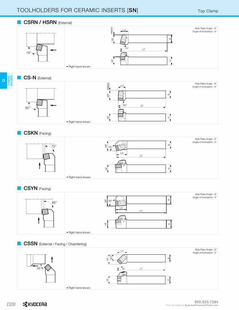
TOOLHOLDERS FOR CERAMIC INSERTS [CN] Top Clamp
• Right-hand shown
� CCLN / HCLN (External / Facing)Side Rake Angle: -6°
Angle of Inclination: -6°
Part Number
Stock
Unit
Dimensions
Sta
ndar
dC
orne
r-R
(RE
)
Spare Parts
Chipbreaker ClampSet Wrench Shim Shim
Screw Lock Pin Wrench
R L H HF B LF LH WF HBKW
CE HCL M S
CCLN§ 2020K-12 Þ Þ
mm
20 20 20 125 32 27 50.8 CB-16 CE-010 LW-4 SP-441
(SP-443)M3X8
(M3X12) - -2525M-12 Þ Þ 25 25 25 150 32 32 -
CCLN§ 3225P-16 Þ Þ 32 32 25 170 35 32 - 0.8 CB-17 CE-220 LW-4 SP-454 M4X10 - -
HCLN§ 16-4D Þ � inch 1.00 1.00 1.00 6.00 1.26 1.25 - 1/32 HCB318 HCL008 LW-4 ICSN433(ICSN453) S-46 NL46L LW-094
� Toolholder Dimensions
� Ceramic Insert Selection Guide
Select the suitable ceramic specifications (Corner-R(RE), Feed Rate, Chamfer, etc.) from the table below. (No.45, Cutting Edge Angle: 0°~15)
• Shim & Shim Screw: When using CN��43 Insert, purchase spare parts in ( ) separately.
Application Cast Iron / Hard Materials Hard Materials / Cast Iron
Ref. Page � B106 � C19
Shape
Toolholder
CCLN§…-12 CNG45.., (CNG43..) CNM45 (CNM43..)
CCLN§…-16 CNG55.. -
� Applicable Inserts
Ceramic CBN (KBN900)
Recommended Cutting Conditions � D43-D44
Application Cast Iron / Hard Materials Cast Iron / Hard Materials
Ref. Page � B106 � B106
Shape
Toolholder
HCLN§…16-4D CNG 45..(43..) CN�A 45..
(43..)
Ceramic Ceramic

D27
H
CU
T-OFF
J
THR
EADIN
G
M
MILLIN
G
N
QUICK CHANG
ETO
OLIN
G
R
TECH
NIC
AL
P
SPARE PAR
TS
T
IND
EX
D
TUR
NIN
G
HO
LDER
S
F
BO
RIN
G
B
TUR
NIN
G
INSER
TS
G
GR
OO
VING
C
CB
N/PC
D
INSER
TS
E
SMALL
TOO
LS
K
DR
ILLING
L
SOLID
TOO
LS
A
INSER
T G
RAD
ES
(Customer Service) 800.823.7284 - Option 1(Technical Support) 800.823.7284 - Option 2
Visit us online at KyoceraPrecisionTools.comÞ : Standard Item � : Phaseout Item (will be removed from next catalog)Contact your local Kyocera sales engineer to upgrade old products to new technology
Top ClampTOOLHOLDERS FOR CERAMIC INSERTS [DN / EN]
• Right-hand shown
� CDJN (External / Copying / Back Turning)Side Rake Angle: -5°
Angle of Inclination: -8°
Part Number
Stock
Unit
Dimensions
Sta
ndar
dC
orne
r-R
(RE
)
Spare Parts
Chipbreaker ClampSet Wrench Shim Shim
Screw
R L H HF B LF LH WF
CDJN§ 2525M-15 Þ Þmm
25 25 25 150 32 320.8 CB-14/15 CE-010 LW-4 556C§ HH5X16
3225P-15 Þ Þ 32 32 25 170 32 32
� Toolholder Dimensions
Application Cast Iron / Hard Materials
Ref. Page � B107
Shape
Toolholder
CDJN§…-15 DNG45..
� Applicable Inserts
Ceramic
• Chipbreaker: CB-14 for Right-hand Toolholder, and CB-15 for Left-hand Toolholder.• Shim: 556CR for Right-hand Toolholder, and 556CL for Left-hand Toolholder.
• Right-hand shown
� CELN (External / Facing)Side Rake Angle: -6°
Angle of Inclination: -6°
Part Number
Stock
Unit
Dimensions
Sta
ndar
dC
orne
r-R
(RE
) Spare Parts
Chipbreaker Clamp Set Wrench Shim Shim Screw
R L H HF B LF LH WF
CELN§ 2525M-13 Þ Þ mm 25 25 25 150 32 32 0.8 CB-16 CE-010 LW-4 SP-342 M3X8
� Toolholder Dimensions
Recommended Cutting Conditions � D43-D44
Recommended Cutting Conditions � D43-D44
Ceramic
Application Cast Iron / Hard Materials
Ref. Page � B107
Shape
Toolholder
CELN§…-13 ENG45..
� Applicable Inserts
D28
D
TUR
NIN
G
HO
LDER
S
800.823.7284Visit us online at KyoceraPrecisionTools.com
Top Clamp
• Right-hand shown
� CSRN / HSRN (External)Side Rake Angle: -6°
Angle of Inclination: -4°
• Right-hand shown
� CS-N (External)
• Right-hand shown
� CSKN (Facing)Side Rake Angle: -6°
Angle of Inclination: -4°
• Right-hand shown
� CSYN (Facing)Side Rake Angle: -6°
Angle of Inclination: -4°
Side Rake Angle: -6°Angle of Inclination: -4°
• Right-hand shown
� CSSN (External / Facing / Chamfering)Side Rake Angle: -6°
Angle of Inclination: 0°
TOOLHOLDERS FOR CERAMIC INSERTS [SN]

D29
H
CU
T-OFF
J
THR
EADIN
G
M
MILLIN
G
N
QUICK CHANG
ETO
OLIN
G
R
TECH
NIC
AL
P
SPARE PAR
TS
T
IND
EX
D
TUR
NIN
G
HO
LDER
S
F
BO
RIN
G
B
TUR
NIN
G
INSER
TS
G
GR
OO
VING
C
CB
N/PC
D
INSER
TS
E
SMALL
TOO
LS
K
DR
ILLING
L
SOLID
TOO
LS
A
INSER
T G
RAD
ES
(Customer Service) 800.823.7284 - Option 1(Technical Support) 800.823.7284 - Option 2
Visit us online at KyoceraPrecisionTools.comÞ : Standard Item � : Phaseout Item (will be removed from next catalog)Contact your local Kyocera sales engineer to upgrade old products to new technology
Top ClampTOOLHOLDERS FOR CERAMIC INSERTS [SN]
� CSDN / HSDN (External / Chamfering)Back Rake Angle: -8.5°
Part Number
Stock
Unit
Dimensions
Sta
ndar
dC
orne
r-R
(RE
) Spare Parts
Chipbreaker Clamp Set Wrench Shim ShimScrew
Lock Pin Wrench
R N L H HF B LF LH WF HBKW WFS020 220 040 HCL M3 S
CSRN§ 20-4E Þ Þ inch 1.25 1.25 1.25 7.00 0.88 1.50 - - 1/32 CB-11 CE-020 LW-4 SP-141 M3X8 - -
CSRN§ 2020K-12 Þ Þ
mm
20 20 20 125 22 22.0 2 -
0.8 CB-11 CE-020 LW-4 SP-141(SP-143)
M3X8 (M3X12) - -2525M-12 Þ Þ 25 25 25 150 22 27.0 - -
3225P-12 Þ Þ 32 32 25 170 22 27.0 - -
3225P-15 Þ 32 32 25 170 30 32.4 - -0.8 CB-51 CE-220 LW-4 SP-162 M4X10 - -
4040R-15 Þ Þ 40 40 40 200 30 43.0 - -
CS-N§ 2525M-12 Þ Þ 25 25 25 150 20 32.0 - - 0.8 CB-11 CE-020 LW-4 SP-141(SP-143)
M3X8(M3X12) - -
CSKN§ 2020K-12 Þ 20 20 20 125 27 25.0 - -0.8 CB-11 CE-020 LW-4 SP-141
(SP-143)M3X8
(M3X12) - -2525M-12 Þ Þ 25 25 25 150 27 32.0 - -
3225P-15 Þ 32 32 25 170 37 32.0 - - 0.8 CB-51 CE-220 LW-4 SP-162 M4X10 - -
CSYN§ 2525M-12 Þ Þ 25 25 25 150 27 32.0 - - 0.8 CB-11 CE-020 LW-4 SP-141(SP-143)
M3X8(M3X12) - -
CSSN§ 16-4D Þ Þ inch 1.00 1.00 1.00 6.00 1.00 1.25 - - 1/32 CB-11 CE-020 LW-4 SP-141 (SP-143)
M3X8(M3X12) - -
CSSN§ 2020K-12 Þ
mm
20 20 20 125 26 25.0 - 160.8 CB-11 CE-020 LW-4 SP-141
(SP-143)M3X8
(M3X12) - -2525M-12 Þ Þ 25 25 25 150 26 32.0 - 23
CSDNN 2020K-12 Þ 20 20 20 125 32 10.0 - -
0.8 - CE-040 LW-4 SP-141(SP-143)
M3X8(M3X12) - -2525M-12 Þ 25 25 25 150 32 12.5 - -
3225P-12 Þ 32 32 25 170 32 12.5 - -
HSRN§ 16-4D Þ Þ
inch
1.00 1.00 1.00 6.00 0.87 1.13 - - 1/32 HCB300 HCL-000(HCL-001) LW-4 ISSN433
(ISSN453) S-46 NL46L LW-094
HSDNN 16-4D Þ 1.00 1.00 1.00 6.00 1.30 0.500 - -1/32 - HCL-002 LW-4 ISSN433
(ISSN453) S-46 NL46L LW-09420-4D Þ 1.25 1.25 1.25 6.00 1.30 0.625 - -
� Toolholder Dimensions
• Shim & Shim Screw : When using SN��43 Insert, purchase spare parts in ( ) separately.
� Applicable Inserts
Application Cast Iron /Hard Materials
Cast Iron /Hard Materials Cast Iron Hard Materials /
Cast Iron When using as toolholder for CBN tools (KBN900), prepare spare parts below separately.
Ref. Page � B109, B110 � B109 � B35 � C19
Shape
Toolholder
Clamp Set Shim Shim Screw
M3 S
CSRN§...-4ECSRN§...-12
SNG45.. (SNG43..)SNM45.. - (SNM43..) (SNM43..) CE-030A SP-143 M3X12
CSRN§...-15 SNG55.. - - - - - -
CS-N§...-12 SNG45.. (SNG43..)SNM45.. - (SNM43..) (SNM43..) CE-030A SP-143 M3X12
CSKN§...-12 SNG45.. (SNG43..) SNM45.. - (SNM43..) (SNM43..) CE-030A SP-143 M3X12
CSKN§...-15 SNG55.. - - - - - -
CSYN§...-12 SNG45.. (SNG43..) SNM45.. - (SNM43..) (SNM43..) CE-030A SP-143 M3X12
CSSN§...-4DCSSN§...-12
SNG45.. (SNG43..)SNM45.. - (SNM43..) (SNM43..) CE-030A SP-143 M3X12
CSDNN...-12 SNG45.. (SNG43..)SNM45.. - (SNM43..) (SNM43..) *- SP-143 M3X12
HSRN§...-4D SNG45.. (SNG43..)SNM45..
(SNGA43..)(SNMA43..) (SNM43..) (SNM43..) HCL-001 ISSN453 S-46
HSDNN...-4D SNG45.. (SNG43..)SNM45..
(SNGA43..)(SNMA43..) (SNM43..) (SNM43..) *- ISSN453 S-46
*CSDNN...-12: Clamp Set CE-040 is used continuously.• Shim & Shim Screw : When using SN��43 Insert, purchase spare parts in ( ) separately.
CBN (KBN900)Ceramic Ceramic Coated Carbide
Recommended Cutting Conditions � D43-D44

D30
D
TUR
NIN
G
HO
LDER
S
(Customer Service) 800.823.7284 - Option 1(Technical Support) 800.823.7284 - Option 2
Visit us online at KyoceraPrecisionTools.comÞ : Standard Item � : Phaseout Item (will be removed from next catalog)
Contact your local Kyocera sales engineer to upgrade old products to new technology
Top ClampTOOLHOLDERS FOR CERAMIC INSERTS [TN]
• Right-hand shown
� CTJN (External)
Side Rake Angle: -6°Angle of Inclination: -4°
• Right-hand shown
� CTUN (Facing)
Side Rake Angle: -6°Angle of Inclination: -4°
Part Number
Stock
Unit
DimensionsS
tand
ard
Cor
ner-
R (R
E) Spare Parts
Chipbreaker Clamp Set Wrench Shim Shim Screw
R L H HF B LF LH WF HBKW
CTJN§ 16-3D Þ Þinch
1.00 1.00 1.00 6.00 0.88 1.25 -1/32 CB-12/13 CE-020 LW-4 SP-221
(SP-223)M3X8
(M3X12)16-4D Þ Þ 1.00 1.00 1.00 6.00 0.88 1.25 -
CTJN§ 2020K-16 Þ Þ
mm
20 20 20 125 21 25 20.8 CB-12/13 CE-020 LW-4 SP-221
(SP-223)M3X8
(M3X12)2525M-16 Þ Þ 25 25 25 150 21 32 -
CTUN§ 2020K-16 Þ Þ 20 20 20 125 27 25 -0.8 CB-13/12 CE-020 LW-4 SP-221
(SP-223)M3X8
(M3X12)2525M-16 Þ Þ 25 25 25 150 27 32 -
� Toolholder Dimensions
• CTJN (Chipbreaker): CB-12 for Right-hand Toolholder, CB-13 for Left-hand Toolholder. CTUN (Chipbreaker): CB-13 for Right-hand Toolholder, CB-12 for Left-hand Toolholder.• Shim & Shim Screw: When using TN��33 Insert, purchase spare parts in ( ) separately.
Recommended Cutting Conditions � D43-D44
� Applicable Inserts
Application Cast Iron / Hard Materials
Hard Materials / Cast Iron
Ref. Page � B111 � C19
Shape
Toolholder
CTJN§…-3DTNG35.. (TNG33..) (TNM33..)
(TNM33..)
CTJN§…-4DTNG45.. (TNG43..) (TNM43..)
(TNM43..)
CTJN§…-16 TNG35.. (TNG33..) (TNM33..)
(TNM33..)CTUN§…-16
Ceramic CBN (KBN900)
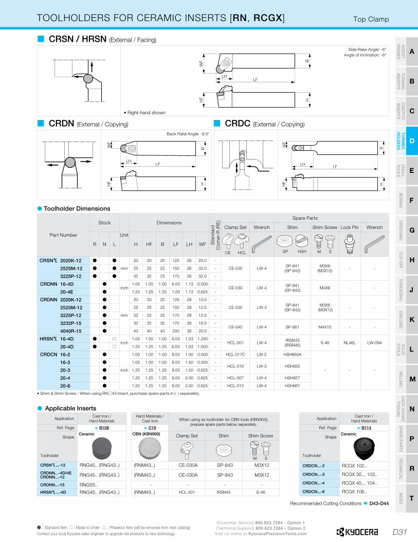
D31
H
CU
T-OFF
J
THR
EADIN
G
M
MILLIN
G
N
QUICK CHANG
ETO
OLIN
G
R
TECH
NIC
AL
P
SPARE PAR
TS
T
IND
EX
D
TUR
NIN
G
HO
LDER
S
F
BO
RIN
G
B
TUR
NIN
G
INSER
TS
G
GR
OO
VING
C
CB
N/PC
D
INSER
TS
E
SMALL
TOO
LS
K
DR
ILLING
L
SOLID
TOO
LS
A
INSER
T G
RAD
ES
(Customer Service) 800.823.7284 - Option 1(Technical Support) 800.823.7284 - Option 2
Visit us online at KyoceraPrecisionTools.comÞ : Standard Item � : Made to Order � : Phaseout Item (will be removed from next catalog)Contact your local Kyocera sales engineer to upgrade old products to new technology
Application Cast Iron /Hard Materials
Ref. Page � B114
Shape
Toolholder
CRDCN...-2 RCGX 102..
CRDCN...-3 RCGX 35.., 103..
CRDCN...-4 RCGX 45.., 104..
CRDCN...-6 RCGX 106..
Top ClampTOOLHOLDERS FOR CERAMIC INSERTS [RN, RCGX]
• Right-hand shown
� CRSN / HRSN (External / Facing)Side Rake Angle: -6°
Angle of Inclination: -6°
Hard Materials / Cast Iron When using as toolholder for CBN tools (KBN900),
prepare spare parts below separately.� C19
Clamp Set Shim Shim Screw
M S
(RNM43..) CE-030A SP-843 M3X12
(RNM43..) CE-030A SP-843 M3X12
- - - -
(RNM43..) HCL-001 IRSN45 S-46
WF
LH
HF H
B
LF
� CRDN (External / Copying) � CRDC (External / Copying)Back Rake Angle: -8.5°
Part Number
Stock
Unit
Dimensions
Sta
ndar
dC
orne
r-R
(RE
) Spare Parts
Clamp Set Wrench Shim Shim Screw Lock Pin Wrench
R N L H HF B LF LH WF
HCLCE SP HSH M S
CRSN§ 2020K-12 Þ Þ
mm
20 20 20 125 26 25.0 -
CE-030 LW-4 SP-841 (SP-843)
M3X8 (M3X12) - -2525M-12 Þ Þ 25 25 25 150 26 32.0 -
3225P-12 Þ Þ 32 32 25 170 26 32.0 -
CRDNN 16-4D Þinch
1.00 1.00 1.00 6.00 1.13 0.500 -CE-030 LW-4 SP-841
(SP-843) M3X8 - -20-4E Þ 1.25 1.25 1.25 7.00 1.13 0.625 -
CRDNN 2020K-12 Þ
mm
20 20 20 125 28 10.0 -
CE-030 LW-4 SP-841(SP-843)
M3X8 (M3X12) - -2525M-12 Þ 25 25 25 150 28 12.5 -
3225P-12 Þ 32 32 25 170 28 12.5 -
3232P-15 Þ 32 32 32 170 35 16.0 -CE-040 LW-4 SP-861 M4X10 - -
4040R-15 Þ 40 40 40 200 35 20.0 -
HRSN§ 16-4D Þ �inch
1.00 1.00 1.00 6.00 1.03 1.250 -HCL-001 LW-4 IRSN43
(IRSN45) S-46 NL46L LW-09420-4D Þ � 1.25 1.25 1.25 6.00 1.03 1.500 -
CRDCN 16-2 Þ
inch
1.00 1.00 1.00 8.00 1.00 0.500 - HCL-017C LW-2 HSH665A
- - -
16-3 Þ 1.00 1.00 1.00 8.00 1.50 0.500 -HCL-016 LW-3 HSH655
20-3 Þ 1.25 1.25 1.25 8.00 1.50 0.625 -
20-4 Þ 1.25 1.25 1.25 8.00 2.00 0.625 - HCL-007 LW-4 HSH657
20-6 Þ 1.25 1.25 1.25 8.00 2.00 0.625 - HCL-013 LW-4 HSH661
� Toolholder Dimensions
• Shim & Shim Screw : When using RN�43 Insert, purchase spare parts in ( ) separately.
Recommended Cutting Conditions � D43-D44
� Applicable Inserts
Application Cast Iron /Hard Materials
Ref. Page � B108
Shape
Toolholder
CRSN§...-12 RNG45.. (RNG43..)
CRDNN...-4D/4ECRDNN...-12 RNG45.. (RNG43..)
CRDNN...-15 RNG55..HRSN§...-4D RNG45.. (RNG43..)
Ceramic CBN (KBN900) Ceramic
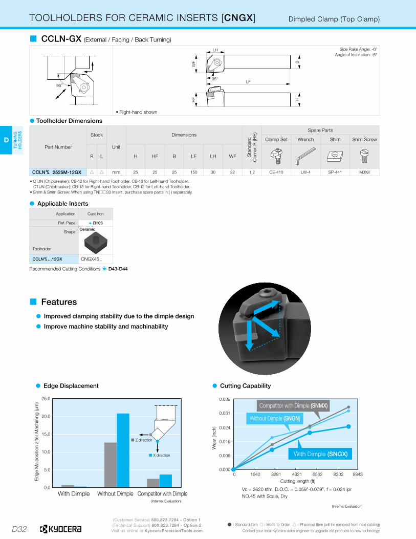
D32
D
TUR
NIN
G
HO
LDER
S
(Customer Service) 800.823.7284 - Option 1(Technical Support) 800.823.7284 - Option 2
Visit us online at KyoceraPrecisionTools.comÞ : Standard Item � : Made to Order � : Phaseout Item (will be removed from next catalog)
Contact your local Kyocera sales engineer to upgrade old products to new technology
• Right-hand shown
� CCLN-GX (External / Facing / Back Turning)Side Rake Angle: -6°
Angle of Inclination: -6°
Dimpled Clamp (Top Clamp)TOOLHOLDERS FOR CERAMIC INSERTS [CNGX]
Part Number
Stock
Unit
Dimensions
Sta
ndar
dC
orne
r-R
(RE
) Spare Parts
Clamp Set Wrench Shim Shim Screw
R L H HF B LF LH WF
CCLN§ 2525M-12GX � � mm 25 25 25 150 30 32 1.2 CE-410 LW-4 SP-441 M3X8
� Toolholder Dimensions
• CTJN (Chipbreaker): CB-12 for Right-hand Toolholder, CB-13 for Left-hand Toolholder. CTUN (Chipbreaker): CB-13 for Right-hand Toolholder, CB-12 for Left-hand Toolholder.• Shim & Shim Screw: When using TN��33 Insert, purchase spare parts in ( ) separately.
Recommended Cutting Conditions � D43-D44
� Applicable Inserts
Application Cast Iron
Ref. Page � B106
Shape
Toolholder
CCLN§…12GX CNGX45..
Ceramic
� Edge Displacement � Cutting Capability
� Features
� Improved clamping stability due to the dimple design
� Improve machine stability and machinability

D33
H
CU
T-OFF
J
THR
EADIN
G
M
MILLIN
G
N
QUICK CHANG
ETO
OLIN
G
R
TECH
NIC
AL
P
SPARE PAR
TS
T
IND
EX
D
TUR
NIN
G
HO
LDER
S
F
BO
RIN
G
B
TUR
NIN
G
INSER
TS
G
GR
OO
VING
C
CB
N/PC
D
INSER
TS
E
SMALL
TOO
LS
K
DR
ILLING
L
SOLID
TOO
LS
A
INSER
T G
RAD
ES
(Customer Service) 800.823.7284 - Option 1(Technical Support) 800.823.7284 - Option 2
Visit us online at KyoceraPrecisionTools.comÞ : Standard Item � : Made to Order � : Phaseout Item (will be removed from next catalog)Contact your local Kyocera sales engineer to upgrade old products to new technology
• Right-hand shown
� CDHN-GX (External / Copying / Back Turning)Side Rake Angle: -5°
Angle of Inclination: -8°
• Right-hand shown
� CDJN-GX (External / Copying / Back Turning)Side Rake Angle: -5°
Angle of Inclination: -8°
Dimpled Clamp (Top Clamp)TOOLHOLDERS FOR CERAMIC INSERTS [DNGX]
Part Number
Stock
Unit
Dimensions
Sta
ndar
dC
orne
r-R
(RE
) Spare Parts
Clamp Set Wrench Shim Shim Screw
R L H HF B LF LH WF
CDHN§ 2525M-12GX � �
mm
25 25 25 150 30 321.2
CE-410LW-4
SP-521M3X8
2525M-15GX � � 25 25 25 150 33 32 CE-430 SP-541
CDJN§ 2525M-12GX � � 25 25 25 150 32 321.2
CE-410LW-4
SP-521M3X8
2525M-15GX � � 25 25 25 150 38 32 CE-430 SP-541
� Toolholder Dimensions
Recommended Cutting Conditions � D43-D44
� Applicable Inserts
Application Cast Iron
Ref. Page � B107
Shape
Toolholder
CDHN§ 2525M-12GX DNGX35 …
2525M-15GX DNGX45 …
CDJN§ 2525M-12GX DNGX35 …
2525M-15GX DNGX45 …
Ceramic
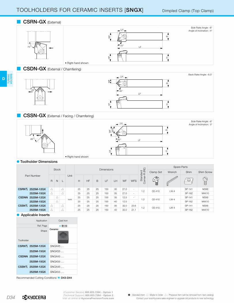
D34
D
TUR
NIN
G
HO
LDER
S
(Customer Service) 800.823.7284 - Option 1(Technical Support) 800.823.7284 - Option 2
Visit us online at KyoceraPrecisionTools.comÞ : Standard Item � : Made to Order � : Phaseout Item (will be removed from next catalog)
Contact your local Kyocera sales engineer to upgrade old products to new technology
• Right-hand shown
� CSRN-GX (External)Side Rake Angle: -6°
Angle of Inclination: -4°
� CSDN-GX (External / Chamfering)
• Right-hand shown
� CSSN-GX (External / Facing / Chamfering)
Back Rake Angle: -8.5°
Side Rake Angle: -6°Angle of Inclination: 0°
Dimpled Clamp (Top Clamp)TOOLHOLDERS FOR CERAMIC INSERTS [SNGX]
Recommended Cutting Conditions � D43-D44
� Applicable Inserts
Application Cast Iron
Ref. Page � B110
Shape
Toolholder
CSRN§ 2525M-12GX SNGX45 …
2525M-15GX SNGX55 …
CSDNN 2525M-12GX SNGX45 …
2525M-15GX SNGX55 …
CSSN§ 2525M-12GX SNGX45 …
2525M-15GX SNGX55 …
Ceramic
Part Number
Stock
Unit
Dimensions
Sta
ndar
dC
orne
r-R
(RE
) Spare Parts
Clamp Set Wrench Shim Shim Screw
R N L H HF B LF LH WF WFS
CSRN§ 2525M-12GX � �
mm
25 25 25 150 30 27.0 -1.2 CE-410 LW-4
SP-141 M3X8
2525M-15GX � � 25 25 25 150 35 27.0 - SP-162 M4X10
CSDNN 2525M-12GX � 25 25 25 150 35 12.5 -1.2 CE-410 LW-4
SP-141 M3X8
2525M-15GX � 25 25 25 150 40 12.5 - SP-162 M4X10
CSSN§ 2525M-12GX � � 25 25 25 150 35 32.0 23.61.2 CE-410 LW-4
SP-141 M3X8
2525M-15GX � � 25 25 25 150 40 32.0 21.1 SP-162 M4X10
� Toolholder Dimensions
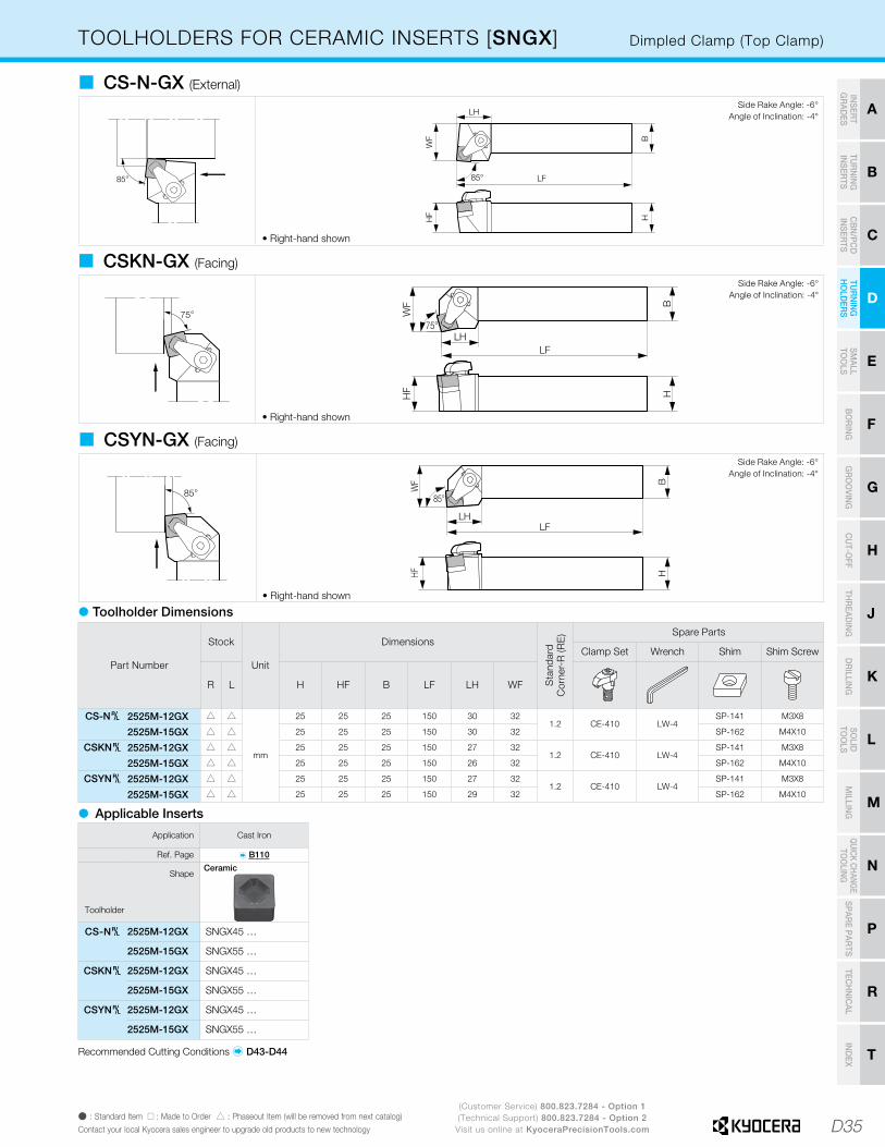
D35
H
CU
T-OFF
J
THR
EADIN
G
M
MILLIN
G
N
QUICK CHANG
ETO
OLIN
G
R
TECH
NIC
AL
P
SPARE PAR
TS
T
IND
EX
D
TUR
NIN
G
HO
LDER
S
F
BO
RIN
G
B
TUR
NIN
G
INSER
TS
G
GR
OO
VING
C
CB
N/PC
D
INSER
TS
E
SMALL
TOO
LS
K
DR
ILLING
L
SOLID
TOO
LS
A
INSER
T G
RAD
ES
(Customer Service) 800.823.7284 - Option 1(Technical Support) 800.823.7284 - Option 2
Visit us online at KyoceraPrecisionTools.comÞ : Standard Item � : Made to Order � : Phaseout Item (will be removed from next catalog)Contact your local Kyocera sales engineer to upgrade old products to new technology
• Right-hand shown
� CS-N-GX (External)Side Rake Angle: -6°
Angle of Inclination: -4°
• Right-hand shown
� CSKN-GX (Facing)
• Right-hand shown
� CSYN-GX (Facing)
Side Rake Angle: -6°Angle of Inclination: -4°
Side Rake Angle: -6°Angle of Inclination: -4°
Dimpled Clamp (Top Clamp)TOOLHOLDERS FOR CERAMIC INSERTS [SNGX]
Part Number
Stock
Unit
Dimensions
Sta
ndar
dC
orne
r-R
(RE
) Spare Parts
Clamp Set Wrench Shim Shim Screw
R L H HF B LF LH WF
CS-N§ 2525M-12GX � �
mm
25 25 25 150 30 321.2 CE-410 LW-4
SP-141 M3X8
2525M-15GX � � 25 25 25 150 30 32 SP-162 M4X10
CSKN§ 2525M-12GX � � 25 25 25 150 27 321.2 CE-410 LW-4
SP-141 M3X8
2525M-15GX � � 25 25 25 150 26 32 SP-162 M4X10
CSYN§ 2525M-12GX � � 25 25 25 150 27 321.2 CE-410 LW-4
SP-141 M3X8
2525M-15GX � � 25 25 25 150 29 32 SP-162 M4X10
� Toolholder Dimensions
Recommended Cutting Conditions � D43-D44
� Applicable Inserts
Application Cast Iron
Ref. Page � B110
Shape
Toolholder
CS-N§ 2525M-12GX SNGX45 …
2525M-15GX SNGX55 …
CSKN§ 2525M-12GX SNGX45 …
2525M-15GX SNGX55 …
CSYN§ 2525M-12GX SNGX45 …
2525M-15GX SNGX55 …
Ceramic

D36
D
TUR
NIN
G
HO
LDER
S
(Customer Service) 800.823.7284 - Option 1(Technical Support) 800.823.7284 - Option 2
Visit us online at KyoceraPrecisionTools.comÞ : Standard Item � : Phaseout Item (will be removed from next catalog)
Contact your local Kyocera sales engineer to upgrade old products to new technology
• Right-hand shown
� CCRN-A (External)Side Rake Angle: -6°
Angle of Inclination: -6°
• Right-hand shown
� CCLN-A (External / Facing)Side Rake Angle: -5°
Angle of Inclination: -5°
Top ClampTOOLHOLDERS FOR SOLID CBN INSERTS [CNM]
Part Number
Stock
Unit
Dimensions
Sta
ndar
dC
orne
r-R
(RE
) Spare Parts
Clamp Set Wrench Shim Shim Screw
R L H HF B LF LH WF
CCRN§ 2525M-09A Þ Þmm
25 25 25 150 27 27 0.8 CE-030A LW-4 SP-429 HH3X12
CCLN§ 2525M-09A Þ Þ 25 25 25 150 28 32 0.8 CE-030A LW-4 SP-429 HH3X12
� Toolholder Dimensions
* For CNM43 Insert toolholder � D26
Recommended Cutting Conditions � D43-D44
� Applicable Inserts
Application Hard Materials / Cast Iron
Ref. Page � C19
Shape
Toolholder
CCRN§...-09ACNM32..
CCLN§...-09A
CBN (KBN900)

D37
H
CU
T-OFF
J
THR
EADIN
G
M
MILLIN
G
N
QUICK CHANG
ETO
OLIN
G
R
TECH
NIC
AL
P
SPARE PAR
TS
T
IND
EX
D
TUR
NIN
G
HO
LDER
S
F
BO
RIN
G
B
TUR
NIN
G
INSER
TS
G
GR
OO
VING
C
CB
N/PC
D
INSER
TS
E
SMALL
TOO
LS
K
DR
ILLING
L
SOLID
TOO
LS
A
INSER
T G
RAD
ES
(Customer Service) 800.823.7284 - Option 1(Technical Support) 800.823.7284 - Option 2
Visit us online at KyoceraPrecisionTools.comÞ : Standard Item � : Phaseout Item (will be removed from next catalog)Contact your local Kyocera sales engineer to upgrade old products to new technology
• Right-hand shown
� CRSN-A (External / Facing)Side Rake Angle: -6°
Angle of Inclination: -6°
� CRDN-A (External / Copying))Back Rake Angle: -8.5°
Top ClampTOOLHOLDERS FOR SOLID CBN INSERTS [RNM]
Part Number
Stock
Unit
Dimensions
Sta
ndar
dC
orne
r-R
(RE
) Spare Parts
Clamp Set Wrench Shim Shim Screw
R N L H HF B LF LH WF
HH BH
CRSN§ 2525M-09A Þ Þ
mm
25 25 25 150 26 32.0- CE-030A LW-4 SP-829 - HH3X12
3225P-09A Þ Þ 32 32 25 170 26 32.0
2525M-12A Þ Þ 25 25 25 150 26 32.0- CE-030A LW-4 -
SP-849(SP-843)
BH3X123225P-12A Þ Þ 32 32 25 170 26 32.0
CRDNN 2525M-09A Þ 25 25 25 150 29 12.5- CE-030A LW-4 SP-829 - HH3X12
3225P-09A Þ 32 32 25 170 29 12.5
2525M-12A Þ 25 25 25 150 28 12.5- CE-030A LW-4 -
SP-849(SP-843)
BH3X123225P-12A Þ 32 32 25 170 28 12.5
� Toolholder Dimensions
• -12A toolholder Shim: When using RN��1204 Insert, purchase spare parts: SP-843 in ( ) separately.
Recommended Cutting Conditions � D43-D44
� Applicable Inserts
Application Hard Materials /Cast Iron
Cast Iron /Hard Materials When using as toolholder for ceramic tools,
prepare spare parts below separately.Ref. Page � C19 � B108
Shape
Toolholder
Shim Shim Screw
CRSN§...-09A RNM32 (RNG33) SP-826 -
CRSN§...-12ARNM42(RNM43)
(RNG43) SP-843 M3X12
(RNG45) SP-841 M3X8
CRDNN...-09A RNM32 (RNG33) SP-826 -
CRDNN...-12ARNM42(RNM43)
(RNG43) SP-843 M3X12
(RNG45) SP-841 M3X8
CBN (KBN900) Ceramic
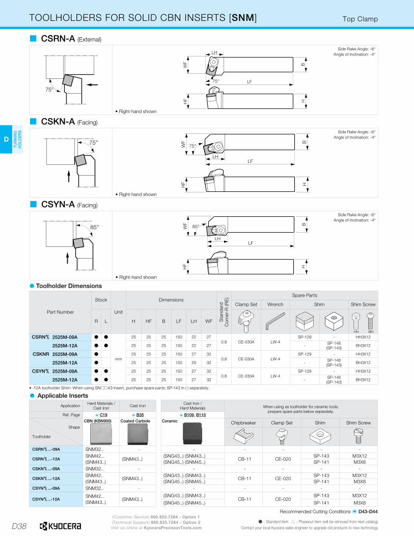
D38
D
TUR
NIN
G
HO
LDER
S
(Customer Service) 800.823.7284 - Option 1(Technical Support) 800.823.7284 - Option 2
Visit us online at KyoceraPrecisionTools.comÞ : Standard Item � : Phaseout Item (will be removed from next catalog)
Contact your local Kyocera sales engineer to upgrade old products to new technology
• Right-hand shown
� CSRN-A (External)Side Rake Angle: -6°
Angle of Inclination: -4°
• Right-hand shown
� CSKN-A (Facing)
• Right-hand shown
� CSYN-A (Facing)
Side Rake Angle: -6°Angle of Inclination: -4°
Side Rake Angle: -6°Angle of Inclination: -4°
Top ClampTOOLHOLDERS FOR SOLID CBN INSERTS [SNM]
Part Number
Stock
Unit
Dimensions
Sta
ndar
dC
orne
r-R
(RE
) Spare Parts
Clamp Set Wrench Shim Shim Screw
R L H HF B LF LH WF
CSRN§ 2525M-09A Þ Þ
mm
25 25 25 150 22 270.8 CE-030A LW-4
SP-129 - HH3X12
2525M-12A Þ Þ 25 25 25 150 22 27 - SP-148(SP-143) BH3X12
CSKNR 2525M-09A Þ 25 25 25 150 27 320.8 CE-030A LW-4
SP-129 - HH3X12
2525M-12A Þ 25 25 25 150 29 32 - SP-148(SP-143) BH3X12
CSYN§ 2525M-09A Þ Þ 25 25 25 150 27 320.8 CE-030A LW-4
SP-129 - HH3X12
2525M-12A Þ Þ 25 25 25 150 27 32 - SP-148(SP-143) BH3X12
� Toolholder Dimensions
• -12A toolholder Shim: When using SN��43 Insert, purchase spare parts: SP-143 in ( ) separately.
� Applicable Inserts
Ceramic
Application Hard Materials / Cast Iron Cast Iron Cast Iron /
Hard Materials When using as toolholder for ceramic tools,prepare spare parts below separately.
Ref. Page � C19 � B35 � B109, B110
Shape
Toolholder
Chipbreaker Clamp Set Shim Shim Screw
CSRN§...-09A SNM32.. - - - - - -
CSRN§...-12ASNM42.. (SNM43..)
(SNM43..)(SNG43..) (SNM43..)
CB-11 CE-020SP-143 M3X12
(SNG45..) (SNM45..) SP-141 M3X8CSKN§...-09A SNM32.. - - - - - -
CSKN§...-12ASNM42.. (SNM43..)
(SNM43..)(SNG43..) (SNM43..)
CB-11 CE-020SP-143 M3X12
(SNG45..) (SNM45..) SP-141 M3X8CSYN§...-09A SNM32.. - - - - - -
CSYN§...-12ASNM42.. (SNM43..)
(SNM43..)(SNG43..) (SNM43..)
CB-11 CE-020SP-143 M3X12
(SNG45..) (SNM45..) SP-141 M3X8
CBN (KBN900) Coated Carbide
HH BH
Recommended Cutting Conditions � D43-D44

D39
H
CU
T-OFF
J
THR
EADIN
G
M
MILLIN
G
N
QUICK CHANG
ETO
OLIN
G
R
TECH
NIC
AL
P
SPARE PAR
TS
T
IND
EX
D
TUR
NIN
G
HO
LDER
S
F
BO
RIN
G
B
TUR
NIN
G
INSER
TS
G
GR
OO
VING
C
CB
N/PC
D
INSER
TS
E
SMALL
TOO
LS
K
DR
ILLING
L
SOLID
TOO
LS
A
INSER
T G
RAD
ES
(Customer Service) 800.823.7284 - Option 1(Technical Support) 800.823.7284 - Option 2
Visit us online at KyoceraPrecisionTools.comÞ : Standard Item � : Phaseout Item (will be removed from next catalog)Contact your local Kyocera sales engineer to upgrade old products to new technology
• Right-hand shown
� CSSN-A (External / Facing / Chamfering)Side Rake Angle: -6°
Angle of Inclination: 0°
� CSDN-A (External / Chamfering)Back Rake Angle: -8.5°
Top ClampTOOLHOLDERS FOR CERAMIC INSERTS [SNM]
Part Number
Stock
Unit
Dimensions
Sta
ndar
dC
orne
r-R
(RE
) Spare Parts
Clamp Set Wrench Shim Shim Screw
R N L H HF B LF LH WF WFS
CSSN§ 2525M-09A Þ Þ
mm
25 25 25 150 26 32.0 250.8 CE-030A LW-4
SP-129 - HH3X12
2525M-12A Þ Þ 25 25 25 150 26 32.0 23 - SP-148(SP-143) BH3X12
CSDNN 2525M-09A Þ 25 25 25 150 32 12.5 -
0.8 CE-040 LW-4SP-129 - HH3X12
3225P-09A Þ 32 32 25 170 32 12.5 -
2525M-12A Þ 25 25 25 150 32 12.5 - - SP-148(SP-143) BH3X12
� Toolholder Dimensions
• -12A toolholder Shim: When using SN��43 Insert, purchase spare parts: SP-143 in ( ) separately.
HH BH
� Applicable Inserts
Ceramic
Application Hard Materials / Cast Iron Cast Iron Cast Iron /
Hard Materials When using as toolholder for ceramic tools,prepare spare parts below separately.
Ref. Page � C19 � B35 � B109, B110
Shape
Toolholder
Chipbreaker Clamp Set Shim Shim Screw
CSSN§...-09A SNM32.. - - - - - -
CSSN§...-12ASNM42.. (SNM43..)
(SNM43..)(SNG43..) (SNM43..)
CB-11 CE-020SP-143 M3X12
(SNG45..) (SNM45..) SP-141 M3X8CSDNN...-09A SNM32..
-- - - - -
CSDNN...-12ASNM42.. (SNM43..)
(SNG43..) (SNM43..)- -
SP-143 M3X12(SNM43..) (SNG45..) (SNM45..) SP-141 M3X8
CBN (KBN900) Coated Carbide
Recommended Cutting Conditions � D43-D44
030A 040

D40
D
TUR
NIN
G
HO
LDER
S
(Customer Service) 800.823.7284 - Option 1(Technical Support) 800.823.7284 - Option 2
Visit us online at KyoceraPrecisionTools.comÞ : Standard Item � : Phaseout Item (will be removed from next catalog)
Contact your local Kyocera sales engineer to upgrade old products to new technology
• Right-hand shown
� CTJN-A (External)Side Rake Angle: -6°
Angle of Inclination: -4°
• Right-hand shown
� CTUN-A (Facing)Side Rake Angle: -6°
Angle of Inclination: -4°
Top ClampTOOLHOLDERS FOR SOLID CBN INSERTS [TNM]
Part Number
Stock
Unit
Dimensions
Sta
ndar
dC
orne
r-R
(RE
) Spare Parts
Clamp Set Wrench Shim Shim Screw
R L H HF B LF LH WF
CTJN§ 2525M-11A Þ Þmm
25 25 25 150 22 32 0.8 CE-030A LW-4 SP-219 HH3X12
CTUN§ 2525M-11A Þ Þ 25 25 25 150 27 32 0.8 CE-030A LW-4 SP-219 HH3X12
� Toolholder Dimensions
� Applicable Inserts
Application Hard Materials / Cast Iron
Cast Iron /Hard Materials
Ref. Page � C19 � B111
Shape
Toolholder
CTJN§...-11ATNM22.. TNG22..
CTUN§...-11A
CBN (KBN900) Ceramic
* TNM33 Insert toolholder is described in � D30
Recommended Cutting Conditions � D43-D44

D41
H
CU
T-OFF
J
THR
EADIN
G
M
MILLIN
G
N
QUICK CHANG
ETO
OLIN
G
R
TECH
NIC
AL
P
SPARE PAR
TS
T
IND
EX
D
TUR
NIN
G
HO
LDER
S
F
BO
RIN
G
B
TUR
NIN
G
INSER
TS
G
GR
OO
VING
C
CB
N/PC
D
INSER
TS
E
SMALL
TOO
LS
K
DR
ILLING
L
SOLID
TOO
LS
A
INSER
T G
RAD
ES
(Customer Service) 800.823.7284 - Option 1(Technical Support) 800.823.7284 - Option 2
Visit us online at KyoceraPrecisionTools.comÞ : Standard Item � : Phaseout Item (will be removed from next catalog)Contact your local Kyocera sales engineer to upgrade old products to new technology
• Right-hand shown
� PRGC-BE (External)
• Right-hand shown
� PRGC-BF (Facing)
Lever LockTOOLHOLDERS FOR BEARING MACHINING [RCMT INSERT]
Part Number
Sto
ck Unit
DimensionsSpare Parts
Applicable Inserts
� B103
Lever LockScrew Shim Shim Pin Punch Wrench
H HF HBH B LF LH WF
PRGCR 2020K-12BE Þ
mm
20 20 - 20 125 22 25LL-1CN LS-1N LR-12C LSP-1 PC-1 FH-2.5
RCMT1204M0-BB2525M-12BE Þ 25 25 - 25 150 25 32
2020K-16BE Þ 20 20 5 20 125 27 29LL-2C LS-1T LR-16C LSP-2 PC-2 FH-2.5
RCMT1606M0-BB2525M-16BE Þ 25 25 - 25 150 27 32
PRGCR 2020K-12BF Þ 20 20 - 20 125 22 25LL-1CN LS-1N LR-12C LSP-1 PC-1 FH-2.5
RCMT1204M0-BB2525M-12BF Þ 25 25 - 25 150 25 32
2020K-16BF Þ 20 20 5 20 125 27 25LL-2C LS-1T LR-16C LSP-2 PC-2 FH-2.5
RCMT1606M0-BB2525M-16BF Þ 25 25 - 25 150 27 32
� Toolholder Dimensions
Recommended Cutting Conditions � D43-D44
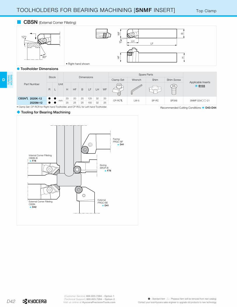
D42
D
TUR
NIN
G
HO
LDER
S
(Customer Service) 800.823.7284 - Option 1(Technical Support) 800.823.7284 - Option 2
Visit us online at KyoceraPrecisionTools.comÞ : Standard Item � : Phaseout Item (will be removed from next catalog)
Contact your local Kyocera sales engineer to upgrade old products to new technology
HF
9° LH
WF
H
LF
B
• Right-hand shown
� CBSN (External Corner Filleting)
Top ClampTOOLHOLDERS FOR BEARING MACHINING [SNMF INSERT]
Part Number
Stock
Unit
DimensionsSpare Parts
Applicable Inserts� B103
Clamp Set Wrench Shim Shim Screw
R L H HF B LF LH WF
CBSN§ 2020K-12 Þ Þmm
20 20 20 125 32 20CP-RC§ LW-5 SP-RC SP3X8 SNMF1204ßß-21
2525M-12 Þ Þ 25 25 25 150 32 25
� Toolholder Dimensions
Recommended Cutting Conditions � D43-D44• Clamp Set: CP-RCR for Right-hand Toolholder, and CP-RCL for Left-hand Toolholder.
� Tooling for Bearing Machining
FacingPRGC-BF
� D41
ExternalPRGC-BE
� D41
External Corner FilletingCBSN � D42
Internal Corner FilletingCBSN-B � F78
BoringSRCP-B
� F78

D43
H
CU
T-OFF
J
THR
EADIN
G
M
MILLIN
G
N
QUICK CHANG
ETO
OLIN
G
R
TECH
NIC
AL
P
SPARE PAR
TS
T
IND
EX
D
TUR
NIN
G
HO
LDER
S
F
BO
RIN
G
B
TUR
NIN
G
INSER
TS
G
GR
OO
VING
C
CB
N/PC
D
INSER
TS
E
SMALL
TOO
LS
K
DR
ILLING
L
SOLID
TOO
LS
A
INSER
T G
RAD
ES
800.823.7284Visit us online at KyoceraPrecisionTools.com
RECOMMENDED CUTTING CONDITIONS
ISO
Cl
assifi
catio
n
WorkpieceMaterial Hardness Cutting Range Applications Recommended
ChipbreakerRecommended
Insert GradeCorner-R
(RE)
Lower Limit - Recommendation - Upper Limit
Vc (sfm) D.O.C. (in) Feed Rate (ipr)
P
Low Carbon SteelLow Carbon Alloy
HB �
300
Finishing(Small D.O.C.)
ContinuousXF
PV710 1/64 820 - 1150 - 1710 0.002 - 0.005 - 0.024 0.001 - 0.004 - 0.009
Interruption PV720 1/32 790 - 1050 - 1570 0.002 - 0.006 - 0.024 0.002 - 0.005 - 0.010
Finishing(Gloss Oriented)
ContinuousXP
TN610 1/64 820 - 1050 - 1310 0.008 - 0.020 - 0.028 0.003 - 0.005 - 0.008
Interruption TN620 1/32 790 - 1020 - 1210 0.008 - 0.020 - 0.028 0.003 - 0.005 - 0.008
Finishing(Tool Life Oriented)
ContinuousXP
PV710 1/64 820 - 980 - 1210 0.008 - 0.020 - 0.028 0.003 - 0.005 - 0.008
Interruption PV720 1/32 790 - 950 - 1120 0.008 - 0.020 - 0.028 0.003 - 0.005 - 0.008
Finishing-Medium(Gloss Oriented)
ContinuousXQ
TN610 1/64 820 - 1050 - 1310 0.020 - 0.039 - 0.059 0.007 - 0.010 - 0.012
Interruption TN620 1/32 790 - 920 - 1120 0.020 - 0.039 - 0.059 0.007 - 0.010 - 0.012
Finishing-Medium(Tool Life Oriented)
ContinuousXQ
PV710 1/32 820 - 980 - 1210 0.020 - 0.039 - 0.059 0.007 - 0.010 - 0.012
Interruption PV720 1/32 790 - 920 - 1120 0.020 - 0.039 - 0.059 0.007 - 0.010 - 0.012
Medium-RoughingContinuous
XSPV720 1/32 720 - 850 - 1050 0.031 - 0.059 - 0.079 0.010 - 0.012 - 0.016
Interruption CA515 1/32 520 - 690 - 850 0.031 - 0.059 - 0.079 0.010 - 0.012 - 0.016
RoughingContinuous
PGCA515 1/32 590 - 720 - 850 0.039 - 0.098 - 0.138 0.008 - 0.012 - 0.016
Interruption CA025P 3/64 490 - 660 - 790 0.039 - 0.098 - 0.138 0.008 - 0.012 - 0.016
Medium-RoughingHigh Feed Rate
ContinuousPT
CA515 1/32 490 - 660 - 790 0.059 - 0.118 - 0.177 0.010 - 0.014 - 0.018
Interruption CA025P 3/64 390 - 590 - 720 0.059 - 0.118 - 0.177 0.010 - 0.014 - 0.018
RoughingHigh Feed Rate
ContinuousPH
CA515 3/64 490 - 660 - 790 0.079 - 0.197 - 0.315 0.016 - 0.024 - 0.031
Interruption CA025P 1/16 390 - 590 - 720 0.079 - 0.197 - 0.315 0.012 - 0.020 - 0.028
Roughing(Low Cutting Force)
Continuous PX(Single Side)
CA515 3/64 490 - 660 - 790 0.079 - 0.197 - 0.315 0.016 - 0.024 - 0.031
Interruption CA025P 1/16 390 - 590 - 720 0.079 - 0.197 - 0.315 0.012 - 0.020 - 0.028
Medium Carbon SteelMedium Carbon Alloy
HB �
300
Finishing(Time Oriented)
Continuous WF(Wiper)
PV710 1/32 660 - 820 - 1050 0.012 - 0.020 - 0.039 0.008 - 0.012 - 0.016
Interruption CA515 1/32 520 - 720 - 920 0.012 - 0.020 - 0.039 0.008 - 0.012 - 0.016
Finishing-Medium(Time Oriented)
Continuous WE(Wiper)
PV710 1/32 590 - 720 - 920 0.039 - 0.079 - 0.118 0.008 - 0.012 - 0.016
Interruption CA025P 1/32 430 - 590 - 790 0.039 - 0.079 - 0.118 0.008 - 0.012 - 0.016
Finishing(Gloss Oriented)
ContinuousPP TN610
1/64 660 - 820 - 1050 0.008 - 0.020 - 0.059 0.002 - 0.006 - 0.011
Interruption 1/32 590 - 750 - 980 0.008 - 0.020 - 0.059 0.002 - 0.008 - 0.014
Finishing(Tool Life Oriented)
ContinuousPP
PV710 1/64 660 - 820 - 1050 0.008 - 0.020 - 0.059 0.002 - 0.006 - 0.011
Interruption PV720 1/32 660 - 790 - 950 0.008 - 0.020 - 0.059 0.002 - 0.008 - 0.014
Finishing-Medium(Gloss Oriented)
ContinuousPQ
TN610 1/32 590 - 750 - 980 0.020 - 0.059 - 0.098 0.004 - 0.008 - 0.012
Interruption TN620 3/64 520 - 720 - 850 0.020 - 0.059 - 0.098 0.004 - 0.007 - 0.010
Finishing-Medium(Tool Life Oriented)
ContinuousPQ
PV710 1/32 520 - 690 - 920 0.020 - 0.059 - 0.098 0.004 - 0.008 - 0.012
Interruption CA025P 1/32 460 - 660 - 790 0.020 - 0.059 - 0.098 0.004 - 0.007 - 0.010
Medium-RoughingContinuous
PGCA515 1/32 490 - 660 - 790 0.039 - 0.098 - 0.138 0.008 - 0.012 - 0.016
Interruption CA025P 3/64 390 - 530 - 660 0.039 - 0.098 - 0.138 0.008 - 0.012 - 0.016
Medium-Roughing High Feed Rate
ContinuousPT
CA515 1/32 390 - 590 - 750 0.059 - 0.118 - 0.177 0.010 - 0.014 - 0.018
Interruption CA025P 3/64 330 - 490 - 660 0.059 - 0.118 - 0.177 0.010 - 0.014 - 0.018
RoughingHigh Feed Rate
ContinuousPH
CA515 3/64 390 - 590 - 750 0.079 - 0.197 - 0.315 0.016 - 0.024 - 0.031
Interruption CA025P 1/16 330 - 490 - 660 0.079 - 0.197 - 0.315 0.012 - 0.020 - 0.028
Roughing(Low Cutting Force)
Continuous PX(Single Side)
CA515 3/64 390 - 590 - 750 0.079 - 0.197 - 0.315 0.016 - 0.024 - 0.031
Interruption CA025P 1/16 330 - 490 - 660 0.079 - 0.197 - 0.315 0.012 - 0.020 - 0.028
High CarbonAlloy
HB �
280
Finishing(Gloss Oriented)
ContinuousPP
TN610 1/64 490 - 660 - 920 0.008 - 0.020 - 0.059 0.002 - 0.006 - 0.011
Interruption TN620 1/32 460 - 590 - 790 0.008 - 0.020 - 0.059 0.002 - 0.008 - 0.014
Finishing(Tool Life Oriented)
ContinuousPP
PV710 1/64 390 - 590 - 850 0.008 - 0.020 - 0.059 0.002 - 0.006 - 0.011
Interruption CA515 1/32 330 - 490 - 660 0.008 - 0.020 - 0.059 0.002 - 0.008 - 0.014
Finishing-MediumContinuous
PQCA515 1/32 390 - 520 - 720 0.020 - 0.059 - 0.098 0.006 - 0.010 - 0.012
Interruption CA025P 1/32 330 - 460 - 590 0.020 - 0.059 - 0.098 0.006 - 0.008 - 0.010
Medium-RoughingContinuous
PGCA515 1/32 390 - 490 - 660 0.039 - 0.079 - 0.118 0.008 - 0.012 - 0.020
Interruption CA025P 1/32 330 - 430 - 590 0.039 - 0.079 - 0.118 0.006 - 0.008 - 0.012
Medium-RoughingHigh Feed Rate
ContinuousPT
CA515 1/32 330 - 460 - 590 0.059 - 0.118 - 0.177 0.010 - 0.014 - 0.018
Interruption CA025P 3/64 260 - 390 - 520 0.059 - 0.118 - 0.177 0.010 - 0.014 - 0.018
RoughingHigh Feed Rate
ContinuousPH
CA515 3/64 330 - 460 - 590 0.079 - 0.197 - 0.315 0.016 - 0.024 - 0.031
Interruption CA025P 1/16 260 - 390 - 520 0.079 - 0.197 - 0.315 0.012 - 0.020 - 0.028
Roughing(Low Cutting Force)
Continuous PX(Single Side)
CA515 3/64 330 - 460 - 590 0.079 - 0.197 - 0.315 0.016 - 0.024 - 0.031
Interruption CA025P 1/16 260 - 390 - 520 0.079 - 0.197 - 0.315 0.012 - 0.020 - 0.028
� Recommended Cutting Conditions - External Turning (Negative Insert) [D.O.C. Indicates Radius]
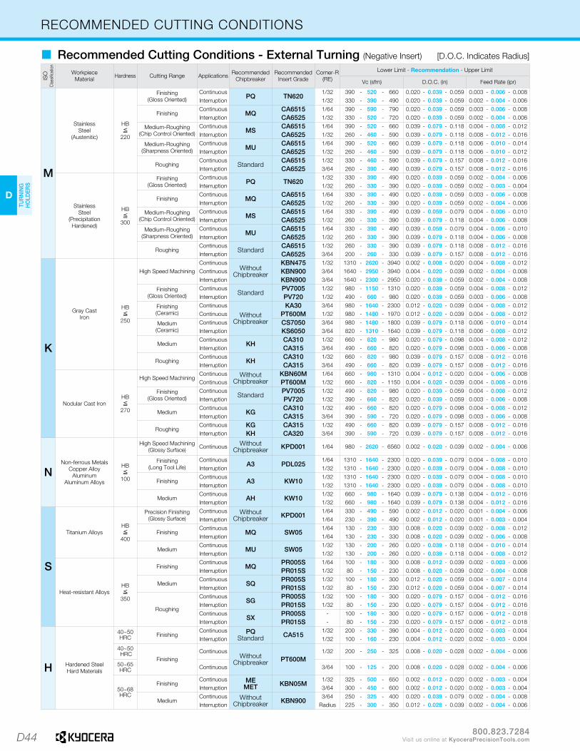
D44
D
TUR
NIN
G
HO
LDER
S
800.823.7284Visit us online at KyoceraPrecisionTools.com
RECOMMENDED CUTTING CONDITIONSIS
O
Clas
sifica
tion
WorkpieceMaterial Hardness Cutting Range Applications Recommended
ChipbreakerRecommended
Insert GradeCorner-R
(RE)
Lower Limit - Recommendation - Upper Limit
Vc (sfm) D.O.C. (in) Feed Rate (ipr)
M
Stainless Steel
(Austenitic)
HB�
220
Finishing(Gloss Oriented)
ContinuousPQ TN620
1/32 390 - 520 - 660 0.020 - 0.039 - 0.059 0.003 - 0.006 - 0.008Interruption 1/32 330 - 390 - 490 0.020 - 0.039 - 0.059 0.002 - 0.004 - 0.006
FinishingContinuous
MQCA6515 1/64 390 - 590 - 790 0.020 - 0.039 - 0.059 0.003 - 0.006 - 0.008
Interruption CA6525 1/32 330 - 520 - 720 0.020 - 0.039 - 0.059 0.002 - 0.004 - 0.006
Medium-Roughing(Chip Control Oriented)
ContinuousMS
CA6515 1/64 390 - 520 - 660 0.039 - 0.079 - 0.118 0.004 - 0.008 - 0.012Interruption CA6525 1/32 260 - 460 - 590 0.039 - 0.079 - 0.118 0.008 - 0.012 - 0.016
Medium-Roughing(Sharpness Oriented)
ContinuousMU
CA6515 1/64 390 - 520 - 660 0.039 - 0.079 - 0.118 0.006 - 0.010 - 0.014Interruption CA6525 1/32 260 - 460 - 590 0.039 - 0.079 - 0.118 0.006 - 0.010 - 0.012
RoughingContinuous
StandardCA6515 1/32 330 - 460 - 590 0.039 - 0.079 - 0.157 0.008 - 0.012 - 0.016
Interruption CA6525 3/64 260 - 390 - 490 0.039 - 0.079 - 0.157 0.008 - 0.012 - 0.016
Stainless Steel
(Precipitation Hardened)
HB�
300
Finishing(Gloss Oriented)
ContinuousPQ TN620
1/32 330 - 390 - 490 0.020 - 0.039 - 0.059 0.002 - 0.004 - 0.006Interruption 1/32 260 - 330 - 390 0.020 - 0.039 - 0.059 0.002 - 0.003 - 0.004
FinishingContinuous
MQCA6515 1/64 330 - 390 - 490 0.020 - 0.039 - 0.059 0.003 - 0.006 - 0.008
Interruption CA6525 1/32 260 - 330 - 390 0.020 - 0.039 - 0.059 0.002 - 0.004 - 0.006
Medium-Roughing(Chip Control Oriented)
ContinuousMS
CA6515 1/64 330 - 390 - 490 0.039 - 0.059 - 0.079 0.004 - 0.006 - 0.010Interruption CA6525 1/32 260 - 330 - 390 0.039 - 0.079 - 0.118 0.004 - 0.006 - 0.008
Medium-Roughing(Sharpness Oriented)
ContinuousMU
CA6515 1/64 330 - 390 - 490 0.039 - 0.059 - 0.079 0.004 - 0.006 - 0.010Interruption CA6525 1/32 260 - 330 - 390 0.039 - 0.079 - 0.118 0.004 - 0.006 - 0.008
RoughingContinuous
StandardCA6515 1/32 260 - 330 - 390 0.039 - 0.079 - 0.118 0.008 - 0.012 - 0.016
Interruption CA6525 3/64 200 - 260 - 330 0.039 - 0.079 - 0.157 0.008 - 0.012 - 0.016
K
Gray Cast Iron
HB�
250
High Speed MachiningContinuous
Without Chipbreaker
KBN475 1/32 1310 - 2620 - 3940 0.002 - 0.008 - 0.020 0.004 - 0.008 - 0.012Continuous KBN900 3/64 1640 - 2950 - 3940 0.004 - 0.020 - 0.039 0.002 - 0.004 - 0.008Interruption KBN900 3/64 1640 - 2300 - 2950 0.020 - 0.039 - 0.059 0.002 - 0.004 - 0.008
Finishing(Gloss Oriented)
ContinuousStandard
PV7005 1/32 980 - 1150 - 1310 0.020 - 0.039 - 0.059 0.004 - 0.008 - 0.012Interruption PV720 1/32 490 - 660 - 980 0.020 - 0.039 - 0.059 0.003 - 0.006 - 0.008
Finishing(Ceramic)
Continuous
Without Chipbreaker
KA30 3/64 980 - 1640 - 2300 0.012 - 0.020 - 0.039 0.004 - 0.008 - 0.012Continuous PT600M 1/32 980 - 1480 - 1970 0.012 - 0.020 - 0.039 0.004 - 0.008 - 0.012
Medium(Ceramic)
Continuous CS7050 3/64 980 - 1480 - 1800 0.039 - 0.079 - 0.118 0.006 - 0.010 - 0.014Interruption KS6050 3/64 820 - 1310 - 1640 0.039 - 0.079 - 0.118 0.006 - 0.008 - 0.012
MediumContinuous
KHCA310 1/32 660 - 820 - 980 0.020 - 0.079 - 0.098 0.004 - 0.008 - 0.012
Interruption CA315 3/64 490 - 660 - 820 0.020 - 0.079 - 0.098 0.003 - 0.006 - 0.008
RoughingContinuous
KHCA310 1/32 660 - 820 - 980 0.039 - 0.079 - 0.157 0.008 - 0.012 - 0.016
Interruption CA315 3/64 490 - 660 - 820 0.039 - 0.079 - 0.157 0.008 - 0.012 - 0.016
Nodular Cast IronHB�
270
High Speed MachiningContinuous Without
ChipbreakerKBN60M 1/64 660 - 980 - 1310 0.004 - 0.012 - 0.020 0.004 - 0.006 - 0.008
Continuous PT600M 1/32 660 - 820 - 1150 0.004 - 0.020 - 0.039 0.004 - 0.008 - 0.016
Finishing(Gloss Oriented)
ContinuousStandard
PV7005 1/32 490 - 820 - 980 0.020 - 0.039 - 0.059 0.004 - 0.008 - 0.012Interruption PV720 1/32 390 - 660 - 820 0.020 - 0.039 - 0.059 0.003 - 0.006 - 0.008
MediumContinuous
KGCA310 1/32 490 - 660 - 820 0.020 - 0.079 - 0.098 0.004 - 0.008 - 0.012
Interruption CA315 3/64 390 - 590 - 720 0.020 - 0.079 - 0.098 0.003 - 0.006 - 0.008
RoughingContinuous KG CA315 1/32 490 - 660 - 820 0.039 - 0.079 - 0.157 0.008 - 0.012 - 0.016Interruption KH CA320 3/64 390 - 590 - 720 0.039 - 0.079 - 0.157 0.008 - 0.012 - 0.016
NNon-ferrous Metals
Copper AlloyAluminum
Aluminum Alloys
HB�
100
High Speed Machining (Glossy Surface) Continuous Without
Chipbreaker KPD001 1/64 980 - 2620 - 6560 0.002 - 0.020 - 0.039 0.002 - 0.004 - 0.006
Finishing(Long Tool Life)
ContinuousA3 PDL025
1/64 1310 - 1640 - 2300 0.020 - 0.039 - 0.079 0.004 - 0.008 - 0.010Interruption 1/32 1310 - 1640 - 2300 0.020 - 0.039 - 0.079 0.004 - 0.008 - 0.010
FinishingContinuous
A3 KW101/32 1310 - 1640 - 2300 0.020 - 0.039 - 0.079 0.004 - 0.008 - 0.010
Interruption 1/32 1310 - 1640 - 2300 0.020 - 0.039 - 0.079 0.004 - 0.008 - 0.010
MediumContinuous
AH KW101/32 660 - 980 - 1640 0.039 - 0.079 - 0.138 0.004 - 0.012 - 0.016
Interruption 1/32 660 - 980 - 1640 0.039 - 0.079 - 0.138 0.004 - 0.012 - 0.016
S
Titanium AlloysHB�
400
Precision Finishing (Glossy Surface)
Continuous Without Chipbreaker KPD001
1/64 330 - 490 - 590 0.002 - 0.012 - 0.020 0.001 - 0.004 - 0.006Interruption 1/64 230 - 390 - 490 0.002 - 0.012 - 0.020 0.001 - 0.003 - 0.004
FinishingContinuous
MQ SW051/64 130 - 230 - 330 0.008 - 0.020 - 0.039 0.002 - 0.008 - 0.012
Interruption 1/64 130 - 230 - 330 0.008 - 0.020 - 0.039 0.002 - 0.006 - 0.008
MediumContinuous
MU SW051/32 130 - 200 - 260 0.020 - 0.039 - 0.118 0.004 - 0.010 - 0.014
Interruption 1/32 130 - 200 - 260 0.020 - 0.039 - 0.118 0.004 - 0.008 - 0.012
Heat-resistant AlloysHB�
350
FinishingContinuous
MQPR005S 1/64 100 - 180 - 300 0.008 - 0.012 - 0.039 0.002 - 0.003 - 0.006
Interruption PR015S 1/32 80 - 150 - 230 0.008 - 0.020 - 0.039 0.002 - 0.004 - 0.008
MediumContinuous
SQPR005S 1/32 100 - 180 - 300 0.012 - 0.020 - 0.059 0.004 - 0.007 - 0.014
Interruption PR015S 1/32 80 - 150 - 230 0.012 - 0.020 - 0.059 0.004 - 0.007 - 0.014
Roughing
ContinuousSG
PR005S 1/32 100 - 180 - 300 0.020 - 0.079 - 0.157 0.004 - 0.012 - 0.016Interruption PR015S 1/32 80 - 150 - 230 0.020 - 0.079 - 0.157 0.004 - 0.012 - 0.016Continuous
SXPR005S - 100 - 180 - 300 0.020 - 0.079 - 0.157 0.006 - 0.012 - 0.018
Interruption PR015S - 80 - 150 - 230 0.020 - 0.079 - 0.157 0.006 - 0.012 - 0.018
H Hardened SteelHard Materials
40~50HRC Finishing
Continuous PQStandard CA515
1/32 200 - 330 - 390 0.004 - 0.012 - 0.020 0.002 - 0.003 - 0.004Interruption 1/32 100 - 160 - 230 0.004 - 0.012 - 0.020 0.002 - 0.003 - 0.004
40~50 HRC
FinishingContinuous
Without Chipbreaker PT600M
1/32 200 - 250 - 325 0.008 - 0.020 - 0.028 0.002 - 0.004 - 0.006
50~65 HRC Continuous 3/64 100 - 125 - 200 0.008 - 0.020 - 0.028 0.002 - 0.004 - 0.006
50~68HRC
FinishingContinuous ME
MET KBN05M1/32 325 - 500 - 650 0.002 - 0.012 - 0.020 0.002 - 0.003 - 0.004
Interruption 3/64 300 - 450 - 600 0.002 - 0.012 - 0.020 0.002 - 0.003 - 0.004
MediumContinuous Without
Chipbreaker KBN9003/64 250 - 325 - 400 0.020 - 0.039 - 0.079 0.002 - 0.004 - 0.008
Interruption Radius 225 - 300 - 350 0.012 - 0.028 - 0.039 0.002 - 0.004 - 0.006
� Recommended Cutting Conditions - External Turning (Negative Insert) [D.O.C. Indicates Radius]