Embed Size (px)
Citation preview

Copyright © 2015 by AVG Automation. All Rights Reserved.
EZ TouchPLC
EZ TouchPLC
2 / 64
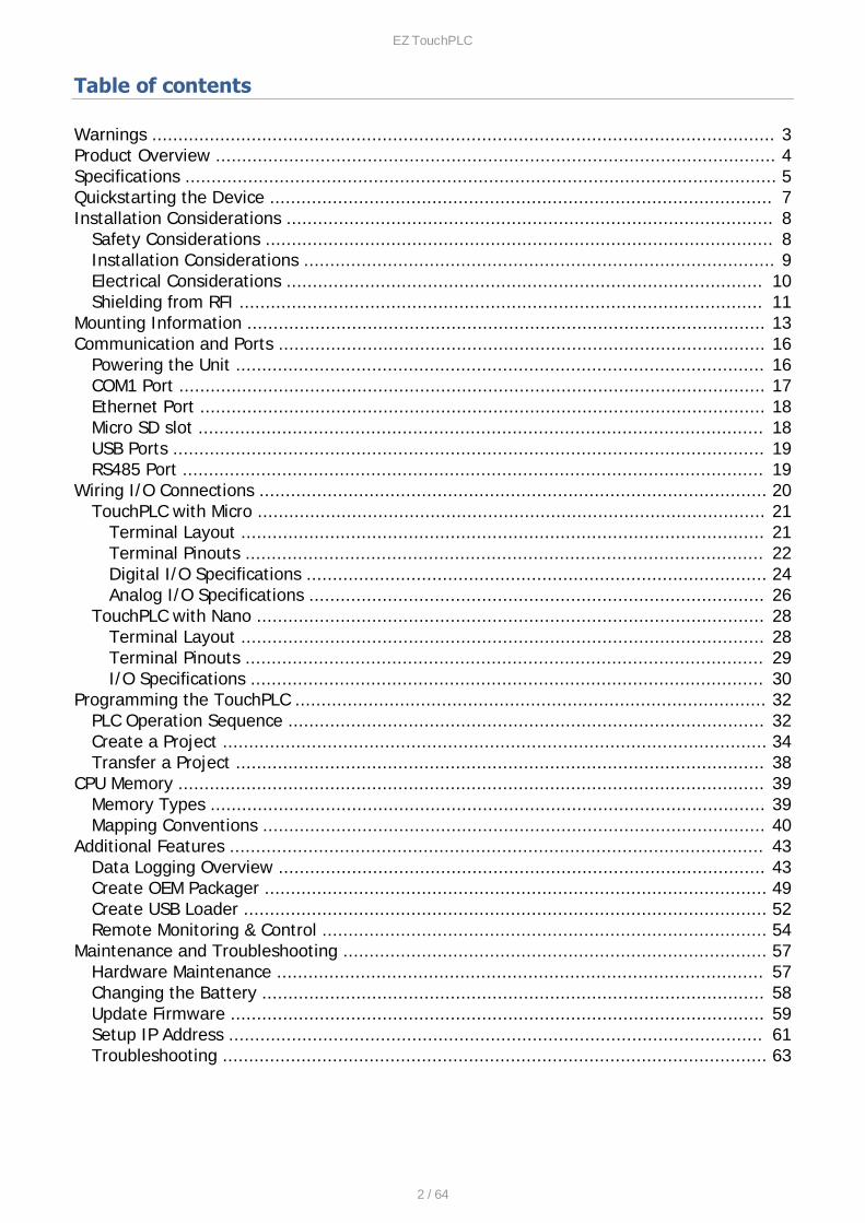
Table of contents
Warnings ....................................................................................................................... 3Product Overview ........................................................................................................... 4Specifications ................................................................................................................. 5Quickstarting the Device ................................................................................................ 7Installation Considerations ............................................................................................. 8
Safety Considerations ................................................................................................. 8Installation Considerations .......................................................................................... 9Electrical Considerations ........................................................................................... 10Shielding from RFI .................................................................................................... 11
Mounting Information ................................................................................................... 13Communication and Ports ............................................................................................. 16
Powering the Unit ..................................................................................................... 16COM1 Port ................................................................................................................ 17Ethernet Port ............................................................................................................ 18Micro SD slot ............................................................................................................ 18USB Ports ................................................................................................................. 19RS485 Port ............................................................................................................... 19
Wiring I/O Connections ................................................................................................. 20TouchPLC with Micro ................................................................................................. 21
Terminal Layout .................................................................................................... 21Terminal Pinouts ................................................................................................... 22Digital I/O Specifications ........................................................................................ 24Analog I/O Specifications ....................................................................................... 26
TouchPLC with Nano ................................................................................................. 28Terminal Layout .................................................................................................... 28Terminal Pinouts ................................................................................................... 29I/O Specifications .................................................................................................. 30
Programming the TouchPLC .......................................................................................... 32PLC Operation Sequence ........................................................................................... 32Create a Project ........................................................................................................ 34Transfer a Project ..................................................................................................... 38
CPU Memory ................................................................................................................ 39Memory Types .......................................................................................................... 39Mapping Conventions ................................................................................................ 40
Additional Features ...................................................................................................... 43Data Logging Overview ............................................................................................. 43Create OEM Packager ................................................................................................ 49Create USB Loader .................................................................................................... 52Remote Monitoring & Control ..................................................................................... 54
Maintenance and Troubleshooting ................................................................................. 57Hardware Maintenance ............................................................................................. 57Changing the Battery ................................................................................................ 58Update Firmware ...................................................................................................... 59Setup IP Address ...................................................................................................... 61Troubleshooting ........................................................................................................ 63

EZ TouchPLC
3 / 64
Warnings
Programmable control devices such as the EZ TouchPLC units are not fail-safe devices and assuch must not be used for stand-alone protection in any application. Unless propersafeguards are used, unwanted start-ups could result in equipment damage or personalinjury. The operator must be made aware of this hazard and appropriate precautions must betaken.
In addition, consideration must be given to the use of an emergency stop function that isindependent of the EZ TouchPLC.
The diagrams and examples in this user manual are included for illustrative purposes only. Themanufacturer cannot assume responsibility or liability for actual use based on the diagramsand examples.
TrademarksThis publication may contain references to products produced and/or offered by othercompanies. The product and company names may be trademarked and are the sole propertyof their respective owners. AVG Automation disclaims any proprietary interest in the marksand names of others.
Manual part number: EZ-TouchPLC-M© Copyright 2015, AVG Automation
All Rights Reserved
No part of this document shall be copied, reproduced, or transmitted in any way without theprior written consent of AVG Automation. AVG Automation retains the exclusive rights to allinformation included in this document.
Designed, Built and Marketed by AVG4140 Utica Ridge Rd. · Bettendorf, IA 52722-1327Phone: 1-877-774-EASY · Fax: 1-877-775-EASY · flash.ezautomation.net
Technical SupportConsult Programming Software Help Directory. You may also find answers to your questions inthe operator interface section of our website @ flash.ezautomation.net. If you still needassistance, please call our technical support at 1-877-774-EASY or FAX us at 1-877-775-EASY.
SELV CircuitsAll electrical circuits connected to the communications port receptacle are rated as Safety ExtraLow Voltage (SELV).
Preventative and Maintenance CleaningNo special preventative measurement is required.
EZ TouchPLC
4 / 64
Product Overview
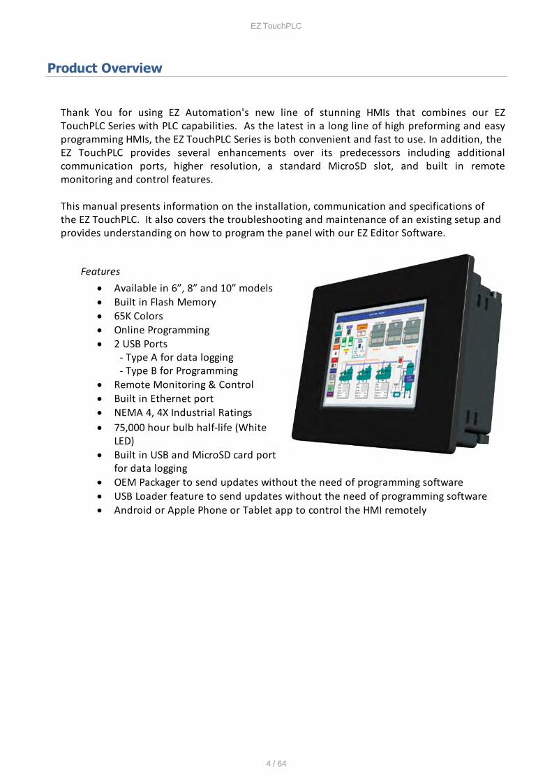
Thank You for using EZ Automation's new line of stunning HMIs that combines our EZTouchPLC Series with PLC capabilities. As the latest in a long line of high preforming and easyprogramming HMIs, the EZ TouchPLC Series is both convenient and fast to use. In addition, the EZ TouchPLC provides several enhancements over its predecessors including additionalcommunication ports, higher resolution, a standard MicroSD slot, and built in remotemonitoring and control features.
This manual presents information on the installation, communication and specifications ofthe EZ TouchPLC. It also covers the troubleshooting and maintenance of an existing setup andprovides understanding on how to program the panel with our EZ Editor Software.
Features· Available in 6”, 8” and 10” models· Built in Flash Memory· 65K Colors· Online Programming· 2 USB Ports
- Type A for data logging - Type B for Programming
· Remote Monitoring & Control· Built in Ethernet port· NEMA 4, 4X Industrial Ratings · 75,000 hour bulb half-life (White
LED)· Built in USB and MicroSD card port
for data logging· OEM Packager to send updates without the need of programming software· USB Loader feature to send updates without the need of programming software· Android or Apple Phone or Tablet app to control the HMI remotely
EZ TouchPLC
5 / 64
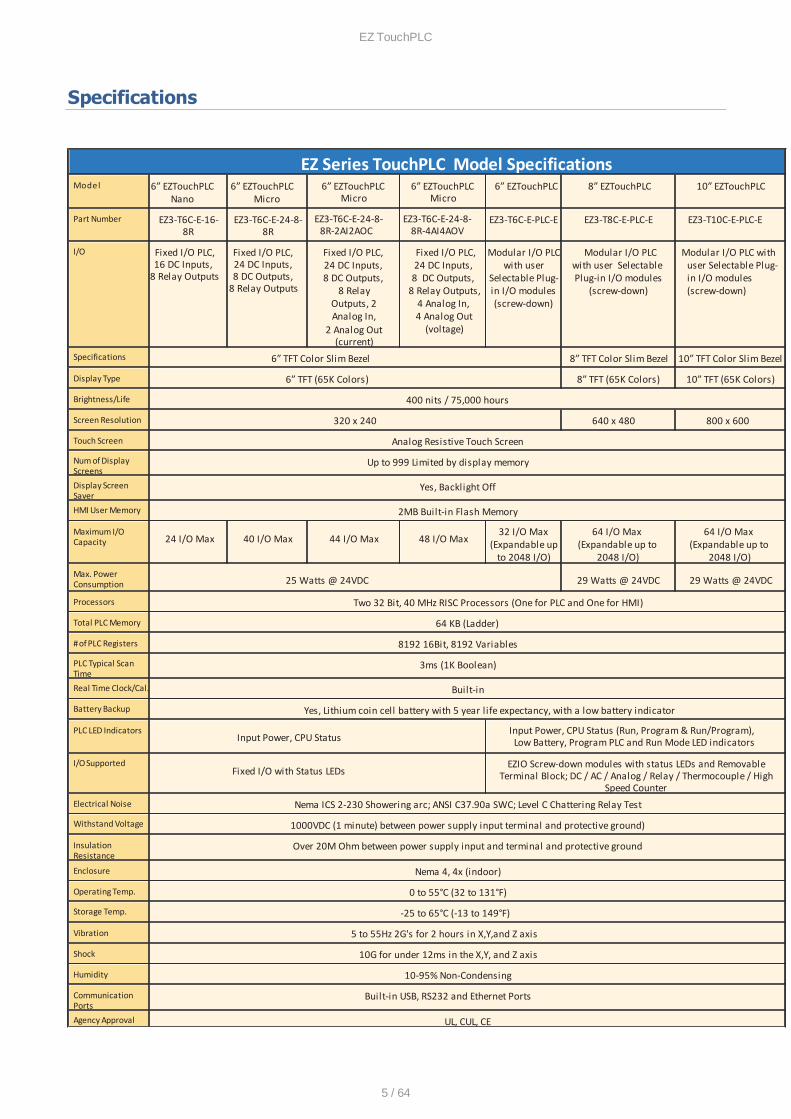
Specifications
EZ Series TouchPLC Model SpecificationsModel 6” EZTouchPLC
Nano6” EZTouchPLC
Micro6” EZTouchPLC
Micro6” EZTouchPLC
Micro6” EZTouchPLC 8” EZTouchPLC 10” EZTouchPLC
Part Number EZ3-T6C-E-16-8R
EZ3-T6C-E-24-8-8R
EZ3-T6C-E-24-8-8R-2AI2AOC
EZ3-T6C-E-24-8-8R-4AI4AOV
EZ3-T6C-E-PLC-E EZ3-T8C-E-PLC-E EZ3-T10C-E-PLC-E
I/O Fixed I/O PLC,16 DC Inputs,
8 Relay Outputs
Fixed I/O PLC, 24 DC Inputs, 8 DC Outputs,
8 Relay Outputs
Fixed I/O PLC, 24 DC Inputs, 8 DC Outputs,
8 RelayOutputs, 2Analog In,
2 Analog Out(current)
Fixed I/O PLC, 24 DC Inputs, 8 DC Outputs,
8 Relay Outputs,4 Analog In, 4 Analog Out
(voltage)
Modular I/O PLCwith user
Selectable Plug-in I/O modules(screw-down)
Modular I/O PLC with user Selectable Plug-in I/O modules
(screw-down)
Modular I/O PLC withuser Selectable Plug-in I/O modules(screw-down)
Specifications 6” TFT Color Slim Bezel 8” TFT Color Slim Bezel 10” TFT Color Slim Bezel
Display Type 6” TFT (65K Colors) 8” TFT (65K Colors) 10” TFT (65K Colors)
Brightness/Life 400 nits / 75,000 hours
Screen Resolution 320 x 240 640 x 480 800 x 600
Touch Screen Analog Resistive Touch Screen
Num of DisplayScreens
Up to 999 Limited by display memory
Display ScreenSaver
Yes, Backlight Off
HMI User Memory 2MB Built-in Flash Memory
Maximum I/OCapacity 24 I/O Max 40 I/O Max 44 I/O Max 48 I/O Max
32 I/O Max(Expandable up
to 2048 I/O)
64 I/O Max (Expandable up to
2048 I/O)
64 I/O Max (Expandable up to
2048 I/O)
Max. PowerConsumption 25 Watts @ 24VDC 29 Watts @ 24VDC 29 Watts @ 24VDC
Processors Two 32 Bit, 40 MHz RISC Processors (One for PLC and One for HMI)
Total PLC Memory 64 KB (Ladder)
# of PLC Registers 8192 16Bit, 8192 Variables
PLC Typical ScanTime
3ms (1K Boolean)
Real Time Clock/Cal. Built-in
Battery Backup Yes, Lithium coin cell battery with 5 year life expectancy, with a low battery indicator
PLC LED IndicatorsInput Power, CPU Status
Input Power, CPU Status (Run, Program & Run/Program), Low Battery, Program PLC and Run Mode LED indicators
I/O SupportedFixed I/O with Status LEDs
EZIO Screw-down modules with status LEDs and RemovableTerminal Block; DC / AC / Analog / Relay / Thermocouple / High
Speed CounterElectrical Noise Nema ICS 2-230 Showering arc; ANSI C37.90a SWC; Level C Chattering Relay Test
Withstand Voltage 1000VDC (1 minute) between power supply input terminal and protective ground)
InsulationResistance
Over 20M Ohm between power supply input and terminal and protective ground
Enclosure Nema 4, 4x (indoor)
Operating Temp. 0 to 55°C (32 to 131°F)
Storage Temp. -25 to 65°C (-13 to 149°F)
Vibration 5 to 55Hz 2G's for 2 hours in X,Y,and Z axis
Shock 10G for under 12ms in the X,Y, and Z axis
Humidity 10-95% Non-Condensing
CommunicationPorts
Built-in USB, RS232 and Ethernet Ports
Agency Approval UL, CUL, CE

EZ TouchPLC
6 / 64
ExternalDimensions
8.048” x 6.146” x 4.325” (204.41 x 156.11 x 109.87mm)
10.894” x 8.748” x4.363”
(276.71 x 222.20 x110.82mm)
13.584”x10.594” x4.299”
(345 x 269.1 x109.20mm)
Weight 2 lbs 3.5 lbs 4.5 lbs

EZ TouchPLC
7 / 64
Quickstarting the Device
This section outlines the steps needed to setup the EZ TouchPLC and get itstarted. This is not intended to explain specific details needed to start yoursystem. Rather, it provides a quick guide to give a broad picture of what isneeded to power-up EZ TouchPLC system.
It is always recommended to make sure you have all the right parts to buildyour system. This is what you will need to get started:
- EZ TouchPLC unit- USB Programming cable*- 2.5mm blade screwdriver for I/O wiring (P/N EZIO-SCDRV)*- Programming Software: EZSeries Editor Programming Software*- 24VDC Power Supply** These accessories have to be purchased separately
Step 1: (Optional) Wire Input / OutputsYou may wire required inputs and outputs now or later. Using the 2.5mmblade screwdriver, simply insert the wire and screw to tighten. Please refer tothe wiring section for information on connecting the Input/Outputs to the EZTouchPLC terminals.
Step 2: Connect PowerConnect the power input wires to the EZ TouchPLC's power terminals asoutlined in the Powering the EZ TouchPLC section. Supply 24VDC nominal (20-28VDC) power to the system. Ensure the indicator LED located on the PLCbase is ON (green LED). If not, remove power from the system and check allthe wiring.
Step 3: Create a ProjectOpen your Touch Panel Editor and create your HMI screen and Ladder Logic.The EZSeries Editor Software Manual explains the programming instructionsin detail. A sample project is outlined in the Programing Section.
Step 4: Transfer Project to UnitThe project can be transfered to the unit either serially or through theEthernet port. If connecting through the USB programming cable, ensure thecable is connect to the unit and PC running the Editing Software. Then usingthe Software, select File > Transfer to Panel. Under the dialog window selectthe appropriate COM port that the USB is connected with and then clickStart.

EZ TouchPLC
8 / 64
Safety Considerations
Please follow all applicable local and national codes to ensure maximum safetyof the equipment and personnel. The installation and operational environmentmust be maintained per the latest revision of these codes.
You are responsible to determine the codes to be followed and to verify thecompliance of equipment, installation, and operation with the latest revision ofthese codes. It is an absolute must to follow all applicable sections of:
-The National Fire Code-The National Electrical Code (NEC)-The National Electrical Manufacturer's Association (NEMA) codes
Safety Guidelines
Safety is the most important element of a proper system installation. Adheringto these safety considerations ensures the safety of yourself and others, as wellas the condition of your equipment. We recommend reviewing the followingsafety guidelines:
1) Disconnecting Main PowerThe main power switch should be easily accessible to the operators andmaintenance personnel. It is important to make sure that all othersources of power including pneumatic and hydraulic are de-energizedbefore starting the work on a machine or process controlled by the HMI.
2) Safety CircuitsMost of the machines are installed with safety circuits such as limitswitches, emergency stop push buttons, and interlocks. These circuitsshould always be hardwired directly to the EZ TouchPLC unit. Thesedevices must be wired in series so that when any one device opens, theunit is automatically de-energized. This removes power to the machine.These circuits should not be altered in any case, since this could result inserious injury or damage to the machine.
3) Fail-Safe OperationOur products are not fault-tolerant. They are not designed or intendedfor use as online control equipment in hazardous environments requiringfail-safe performance, such as in operation of nuclear facilities, aircraftnavigation or communication systems, air traffic control, direct life-support machines, weapons systems, clutch control systems on presses, inwhich the failure of the product could lead directly to death, personalinjury or severe physical or environmental damage. External fail-safe and/or redundant components are required to make your control system fail-safe.
EZ TouchPLC
9 / 64
Installation Considerations
Our products have been designed and tested for operation in the mostdemanding industrial environments. Modern solid-state industrial controls arecomplex electronic equipment that operate at low levels of voltage and current,co-existing with components that operate at much higher levels of power. Thedifference in operating power characteristics between the high and low powercontrol devices creates the possibility of unwanted signals being generated, thuscausing interference. The interference, which is a by-product of electrical noise,is not present at all times. However, if it appears at random and for brief periodsof time, it can cause disruptions and errors in the operation of a control system.
Enhancement of a system's noise level immunity and its tolerance to otherenvironmental hazards can be accomplished by following proper systeminstallation guidelines. The recommendations are of a general nature andconstitute good industrial installation practice.
General Environmental ConsiderationsAvoid installing the EZ TouchPLC unit in areas where the following conditionsmay exist:
o Environmental temperatures above or below those specified for the EZTouchPLC unit
o Prolonged exposure to humidity and liquids which may be sprayed orsplashed on the equipment
o Dusty environments where airborne particles may accumulate onequipment causing reduction of heat dissipation and reduction ineffective electrical spacing between components
o Areas with excessive vibrationo Areas with high-radiated electrical noise, such as near fields of
transmitting antennas and areas in close proximity of arc weldingstations
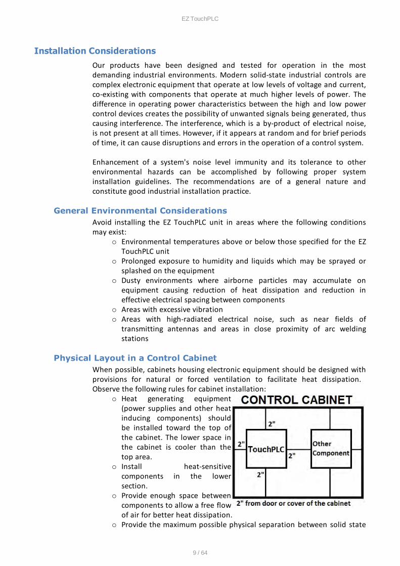
Physical Layout in a Control CabinetWhen possible, cabinets housing electronic equipment should be designed withprovisions for natural or forced ventilation to facilitate heat dissipation. Observe the following rules for cabinet installation:
o Heat generating equipment(power supplies and other heatinducing components) shouldbe installed toward the top ofthe cabinet. The lower space inthe cabinet is cooler than thetop area.
o Install heat-sensitivecomponents in the lowersection.
o Provide enough space betweencomponents to allow a free flowof air for better heat dissipation.
o Provide the maximum possible physical separation between solid state

EZ TouchPLC
10 / 64
and electromechanical controls. If possible, the electromechanicalcontrols (motors, starters, solenoids, etc.) should be housed separatelyor at the farthest point when enclosed within the cabinet.
We recommend that the unit has a minimum clear space of 2" on all sidesfor adequate ventilation as shown in the image on the right.
Electrical Considerations
This section is designed to provide you with a very basic understanding ofelectrical noise and how to keep it away from CPUs. Industrial plants have anumber of generators of electrical noise that are sometimes also referred to asRadio Frequency Interference (RFI). Anytime an inductive load like a motor,motor starter, or solenoid is turned off, it generates a burst of excess energythat has to flow back to ground, just like electrical energy from a lightning stormhas to flow back to Earth. RFI is short bursts of electrical energy at very highfrequencies. Other sources include RF Welders or Radio Transmitters.
Effect of RFI on Electronic Automation EquipmentElectronic controls use faster and faster CPUs today. These CPUs are alsooperating at 2.5V to 5VDC logic level power supply. RFI, if allowed to enter theCPU inside, is a killer of logic. A CPU under this environment loses its brain andbehaves erratically. A smart industrial-grade CPU like the unit's card engine,when faced with RFI, halts its operation instead of giving false outputs.
Types of RFIRFI enters electronic controls in two ways: radiated RFI or conducted RFI. Formost practical purposes, electronic devices, unless sitting right next to apowerful RFI transmitter, will not be affected by noise because air space severelyattenuates such interference. On the other hand, conducted RFI travels overconductive surfaces such as power supply wires, electrical wiring of field devices,and worst of all; improper ground planes.
Equipment cabinets usually incorporate one or two doors and/or hinged cabinetpanels. Relying on door hinges and swinging panels for a good metallic bondbetween hinged parts and the main body of the cabinet does not insureadequate grounding. Instead, the use of ground straps is recommended. It isvital for the reliable operation of any electronic device to have any of its metallicsurfaces well grounded to Earth. This not only provides for safe operation, it willalso drain out any conducted RFI to Earth, away from the CPU's signal ground.
EZ TouchPLC
11 / 64
Shielding from RFIShielded Cables
Power cables, I/O cables or wiring, and communication cables should all beseparate so that they do not couple the conducted RFI on any of these wires/cables. Another path for RFI into the PLC is through its RS232 port. Hence, thecables to this port must be shielded properly.
Equipment Cabinets
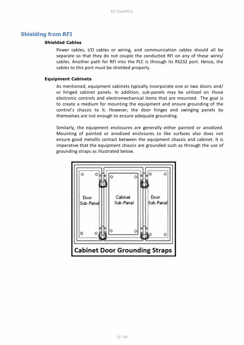
As mentioned, equipment cabinets typically incorporate one or two doors and/or hinged cabinet panels. In addition, sub-panels may be utilized on thoseelectronic controls and electromechanical items that are mounted. The goal isto create a medium for mounting the equipment and ensure grounding of thecontrol's chassis to it. However, the door hinges and swinging panels bythemselves are not enough to ensure adequate grounding.
Similarly, the equipment enclosures are generally either painted or anodized.Mounting of painted or anodized enclosures to like surfaces also does notensure good metallic contact between the equipment chassis and cabinet. It isimperative that the equipment chassis are grounded such as through the use ofgrounding straps as illustrated below.

EZ TouchPLC
12 / 64
Cabinet Wiring
The wiring of the EZ TouchPLC unit to the “feld” outside the cabinet must be bydesign. The wiring cannot be random in order to get the various points of thecabinet and the “feld” electrically connected. Below are some general rules thatapply in most situations:
o Provide a separate power source to electronic controls and keep thispower bus away from any I/O power.
o The cabinet should be wired with a safety ground (the main safetyground wire gauge is determined by the cabinet's total currentconsumption) and in accordance with all electrical code requirements.
o Once the cabinet doors, stationary sub-panels and swing-out sub-panelshave been “strapped” to the main cabinet, it is not necessary to runsafety ground wires from the equipment chassis terminals to the mainsafety ground connection.
o The safety ground terminal of each component can, and should be,connected with the shortest wire possible, to the cabinet or sub-panelframe.
o Plan the wiring routing. Keep all switched power in separate ducts and ifthere is AC and DC power being switched, keep the wiring of eachbranch separate from all wires and cables carrying low level signals.
o Keep all three phase power outside of the cabinet, but if it becomesnecessary, keep the runs as short as possible and maintain themaximum possible distance between the three phase bus and all otherwiring.
o Primary power leads to the control equipment (Base power terminals)should be made with a two wire twisted cable with approximately 12turns per foot. The length of these cables should be kept to a minimum,and to the greatest extent possible, such cable runs should be keptseparate from other wiring.
EZ TouchPLC
13 / 64
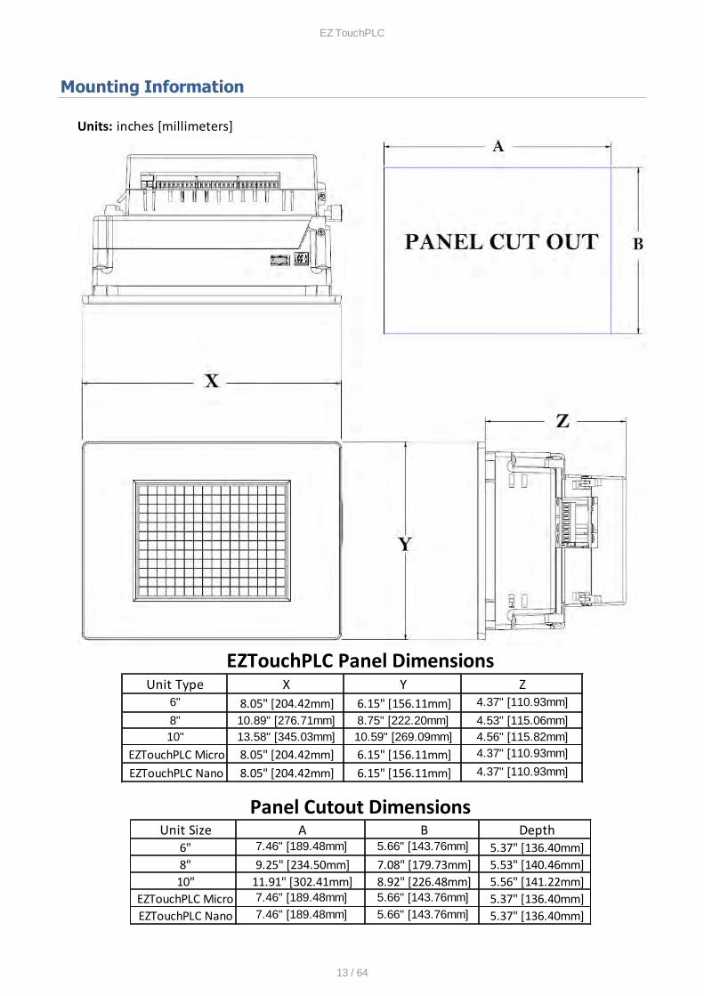
Mounting Information
Units: inches [millimeters]
EZTouchPLC Panel DimensionsUnit Type X Y Z
6" 8.05" [204.42mm] 6.15" [156.11mm] 4.37" [110.93mm]
8" 10.89" [276.71mm] 8.75" [222.20mm] 4.53" [115.06mm]10" 13.58" [345.03mm] 10.59" [269.09mm] 4.56" [115.82mm]
EZTouchPLC Micro 8.05" [204.42mm] 6.15" [156.11mm] 4.37" [110.93mm]
EZTouchPLC Nano 8.05" [204.42mm] 6.15" [156.11mm] 4.37" [110.93mm]
Panel Cutout DimensionsUnit Size A B Depth
6" 7.46" [189.48mm] 5.66" [143.76mm] 5.37" [136.40mm]8" 9.25" [234.50mm] 7.08" [179.73mm] 5.53" [140.46mm]10" 11.91" [302.41mm] 8.92" [226.48mm] 5.56" [141.22mm]
EZTouchPLC Micro 7.46" [189.48mm] 5.66" [143.76mm] 5.37" [136.40mm]EZTouchPLC Nano 7.46" [189.48mm] 5.66" [143.76mm] 5.37" [136.40mm]
EZ TouchPLC
14 / 64
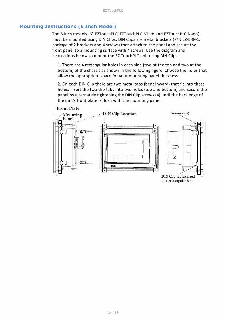
Mounting Instructions (6 Inch Model)
The 6-inch models (6" EZTouchPLC, EZTouchPLC Micro and EZTouchPLC Nano)must be mounted using DIN Clips. DIN Clips are metal brackets (P/N EZ-BRK-1,package of 2 brackets and 4 screws) that attach to the panel and secure thefront panel to a mounting surface with 4 screws. Use the diagram andinstructions below to mount the EZ TouchPLC unit using DIN Clips.
1. There are 4 rectangular holes in each side (two at the top and two at thebottom) of the chassis as shown in the following figure. Choose the holes thatallow the appropriate space for your mounting panel thickness.
2. On each DIN Clip there are two metal tabs (bent inward) that fit into theseholes. Insert the two clip tabs into two holes (top and bottom) and secure thepanel by alternately tightening the DIN Clip screws (4) until the back edge ofthe unit's front plate is flush with the mounting panel.
EZ TouchPLC
15 / 64
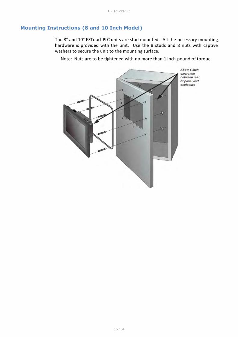
Mounting Instructions (8 and 10 Inch Model)
The 8" and 10" EZTouchPLC units are stud mounted. All the necessary mountinghardware is provided with the unit. Use the 8 studs and 8 nuts with captivewashers to secure the unit to the mounting surface.
Note: Nuts are to be tightened with no more than 1 inch-pound of torque.
EZ TouchPLC
16 / 64
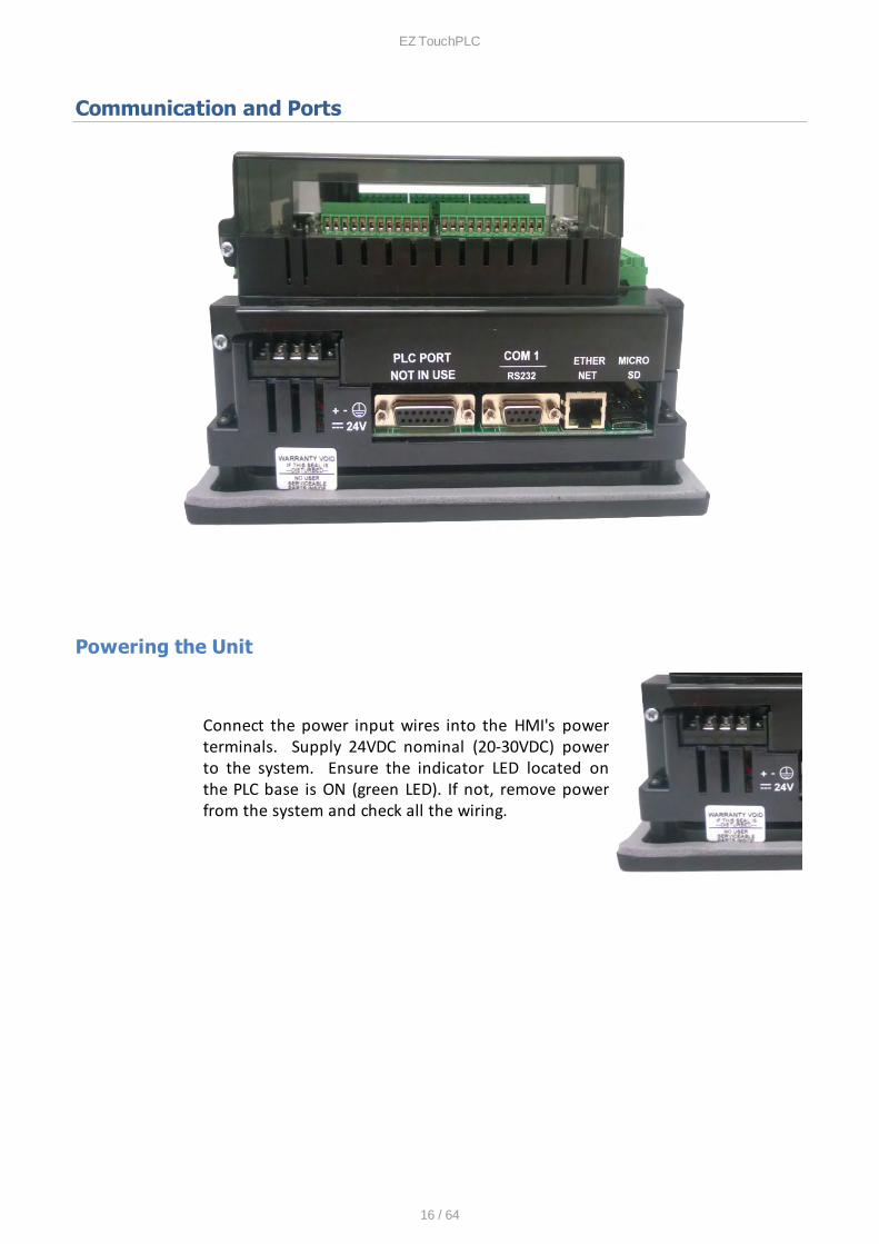
Communication and Ports
Powering the Unit
Connect the power input wires into the HMI's powerterminals. Supply 24VDC nominal (20-30VDC) powerto the system. Ensure the indicator LED located onthe PLC base is ON (green LED). If not, remove powerfrom the system and check all the wiring.
EZ TouchPLC
17 / 64
COM1 Port
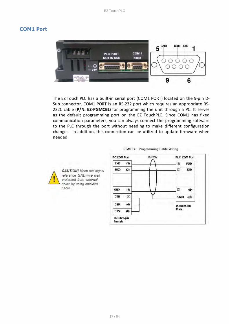
The EZ Touch PLC has a built-in serial port (COM1 PORT) located on the 9-pin D-Sub connector. COM1 PORT is an RS-232 port which requires an appropriate RS-232C cable (P/N: EZ-PGMCBL) for programming the unit through a PC. It servesas the default programming port on the EZ TouchPLC. Since COM1 has fixedcommunication parameters, you can always connect the programming softwareto the PLC through the port without needing to make different configurationchanges. In addition, this connection can be utilized to update firmware whenneeded.
EZ TouchPLC
18 / 64
Ethernet Port
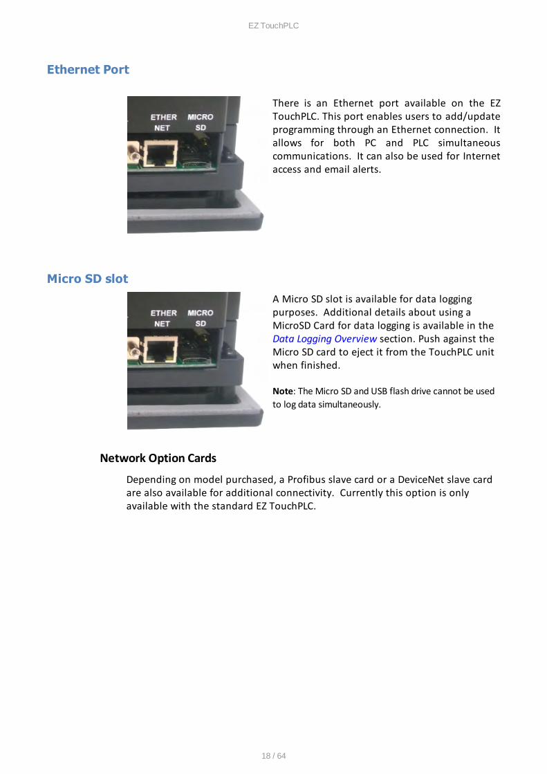
There is an Ethernet port available on the EZTouchPLC. This port enables users to add/updateprogramming through an Ethernet connection. Itallows for both PC and PLC simultaneouscommunications. It can also be used for Internetaccess and email alerts.
Micro SD slot
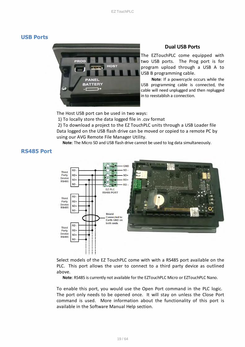
A Micro SD slot is available for data loggingpurposes. Additional details about using aMicroSD Card for data logging is available in the Data Logging Overview section. Push against theMicro SD card to eject it from the TouchPLC unitwhen finished.
Note: The Micro SD and USB flash drive cannot be usedto log data simultaneously.
Network Option Cards
Depending on model purchased, a Profibus slave card or a DeviceNet slave cardare also available for additional connectivity. Currently this option is onlyavailable with the standard EZ TouchPLC.
EZ TouchPLC
19 / 64
USB Ports
Dual USB PortsThe EZTouchPLC come equipped withtwo USB ports. The Prog port is forprogram upload through a USB A toUSB B programming cable.
Note: If a powercycle occurs while theUSB programming cable is connected, thecable will need unplugged and then repluggedin to reestablish a connection.
The Host USB port can be used in two ways: 1) To locally store the data logged file in .csv format 2) To download a project to the EZ TouchPLC units through a USB Loader file Data logged on the USB flash drive can be moved or copied to a remote PC byusing our AVG Remote File Manager Utility.
Note: The Micro SD and USB flash drive cannot be used to log data simultaneously.
RS485 Port
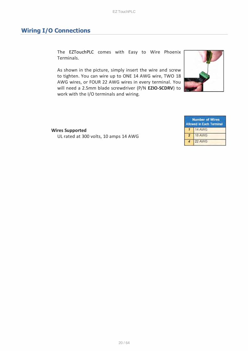
Select models of the EZ TouchPLC come with with a RS485 port available on thePLC. This port allows the user to connect to a third party device as outlinedabove.
Note: RS485 is currently not available for the EZTouchPLC Micro or EZTouchPLC Nano.
To enable this port, you would use the Open Port command in the PLC logic. The port only needs to be opened once. It will stay on unless the Close Portcommand is used. More information about the functionality of this port isavailable in the Software Manual Help section.
EZ TouchPLC
20 / 64
Wiring I/O Connections
The EZTouchPLC comes with Easy to Wire PhoenixTerminals.
As shown in the picture, simply insert the wire and screwto tighten. You can wire up to ONE 14 AWG wire, TWO 18AWG wires, or FOUR 22 AWG wires in every terminal. Youwill need a 2.5mm blade screwdriver (P/N EZIO-SCDRV) towork with the I/O terminals and wiring.
Wires SupportedUL rated at 300 volts, 10 amps 14 AWG
EZ TouchPLC
21 / 64
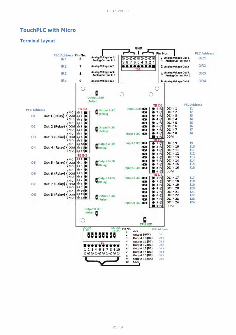
TouchPLC with Micro
Terminal Layout
EZ TouchPLC
22 / 64
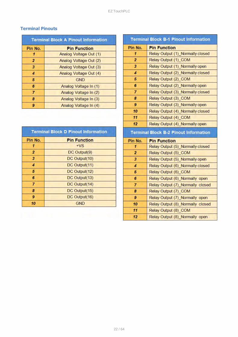
Terminal Pinouts

EZ TouchPLC
23 / 64
EZ TouchPLC
24 / 64
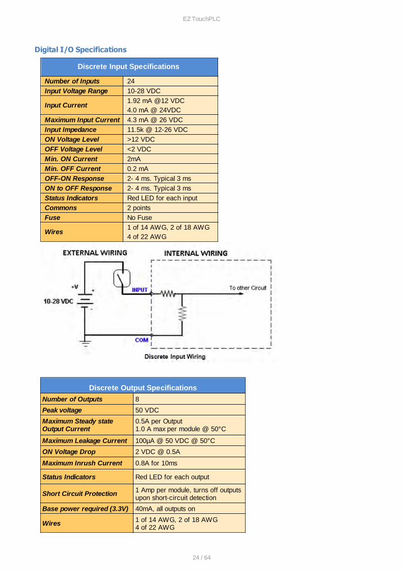
Digital I/O Specifications
Discrete Input Specifications
Number of Inputs 24
Input Voltage Range 10-28 VDC
Input Current1.92 mA @12 VDC4.0 mA @ 24VDC
Maximum Input Current 4.3 mA @ 26 VDC
Input Impedance 11.5k @ 12-26 VDC
ON Voltage Level >12 VDC
OFF Voltage Level <2 VDC
Min. ON Current 2mA
Min. OFF Current 0.2 mA
OFF-ON Response 2- 4 ms. Typical 3 ms
ON to OFF Response 2- 4 ms. Typical 3 ms
Status Indicators Red LED for each input
Commons 2 points
Fuse No Fuse
Wires1 of 14 AWG, 2 of 18 AWG4 of 22 AWG
Discrete Output Specifications
Number of Outputs 8
Peak voltage 50 VDC
Maximum Steady stateOutput Current
0.5A per Output1.0 A max per module @ 50°C
Maximum Leakage Current 100µA @ 50 VDC @ 50°C
ON Voltage Drop 2 VDC @ 0.5A
Maximum Inrush Current 0.8A for 10ms
Status Indicators Red LED for each output
Short Circuit Protection 1 Amp per module, turns off outputsupon short-circuit detection
Base power required (3.3V) 40mA, all outputs on
Wires 1 of 14 AWG, 2 of 18 AWG4 of 22 AWG
EZ TouchPLC
25 / 64
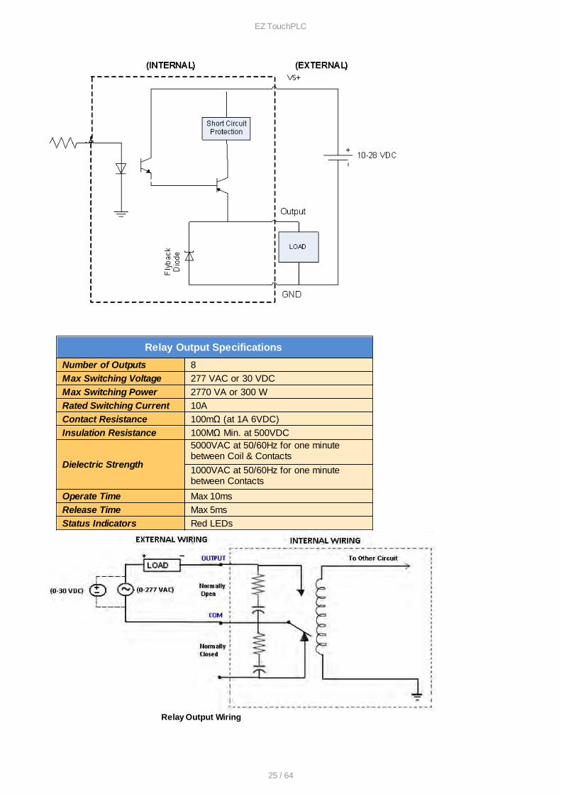
Relay Output Specifications
Number of Outputs 8
Max Switching Voltage 277 VAC or 30 VDC
Max Switching Power 2770 VA or 300 W
Rated Switching Current 10A
Contact Resistance 100mΩ (at 1A 6VDC)
Insulation Resistance 100MΩ Min. at 500VDC
Dielectric Strength
5000VAC at 50/60Hz for one minutebetween Coil & Contacts
1000VAC at 50/60Hz for one minute between Contacts
Operate Time Max 10ms
Release Time Max 5ms
Status Indicators Red LEDs
Relay Output Wiring
EZ TouchPLC
26 / 64
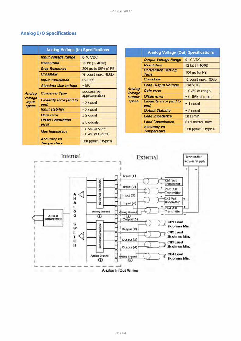
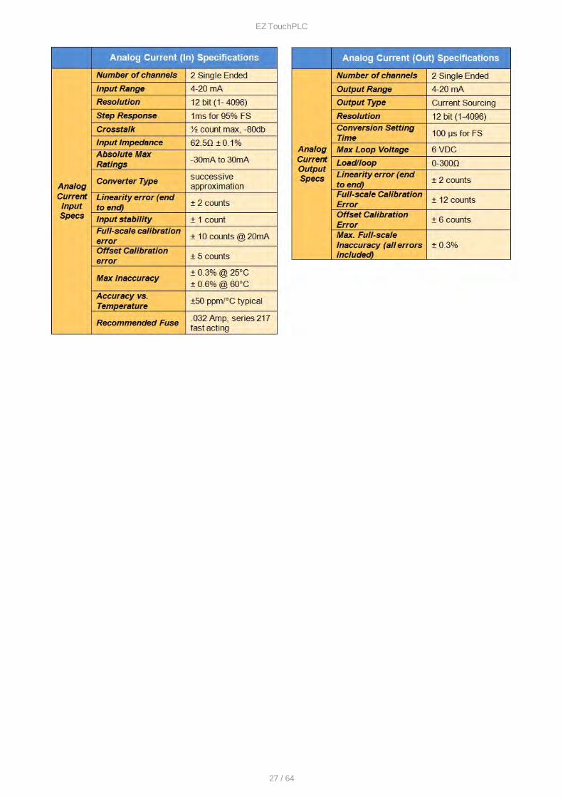
Analog I/O Specifications
EZ TouchPLC
27 / 64
EZ TouchPLC
28 / 64
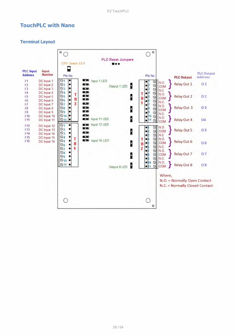
TouchPLC with Nano
Terminal Layout
EZ TouchPLC
29 / 64
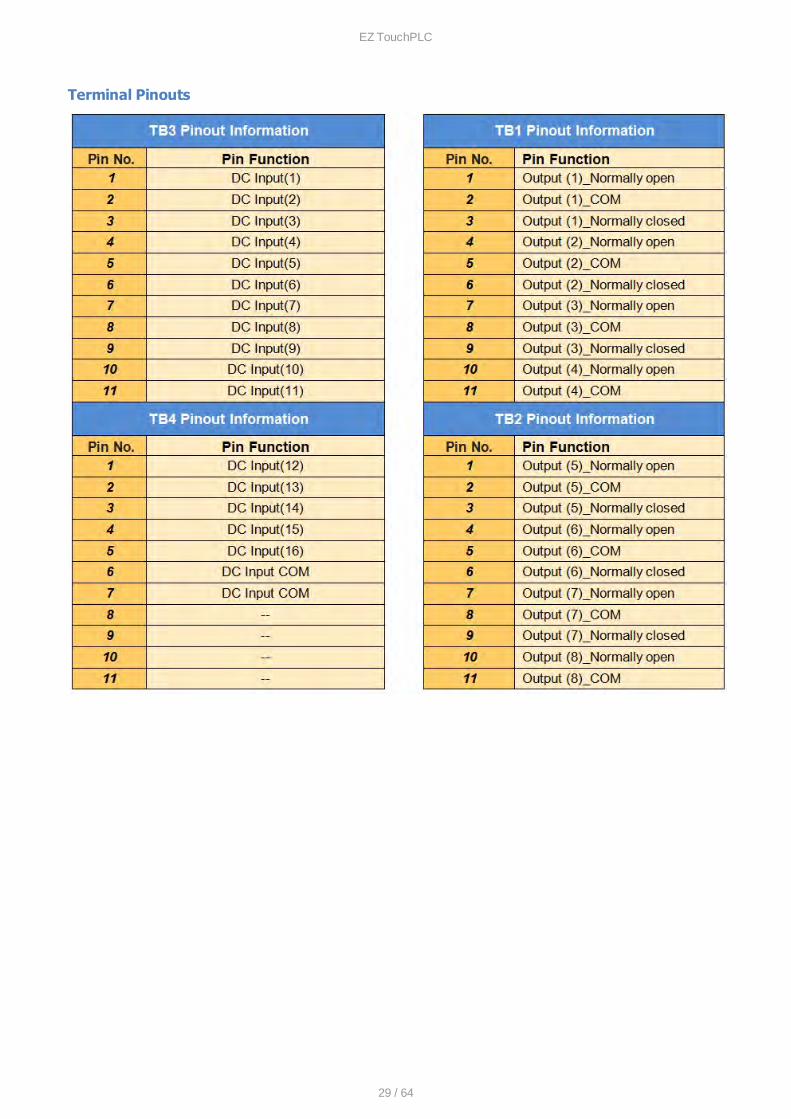
Terminal Pinouts
EZ TouchPLC
30 / 64
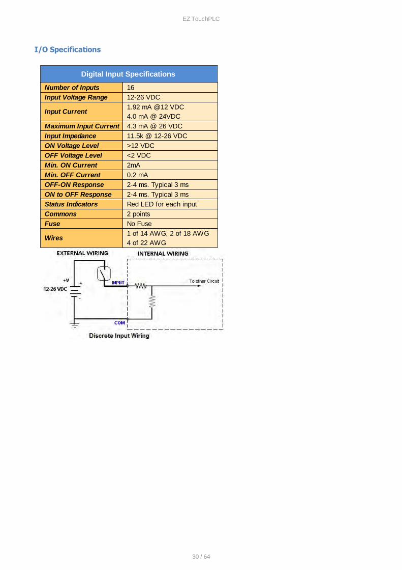
I/O Specifications
Digital Input Specifications
Number of Inputs 16
Input Voltage Range 12-26 VDC
Input Current1.92 mA @12 VDC4.0 mA @ 24VDC
Maximum Input Current 4.3 mA @ 26 VDC
Input Impedance 11.5k @ 12-26 VDC
ON Voltage Level >12 VDC
OFF Voltage Level <2 VDC
Min. ON Current 2mA
Min. OFF Current 0.2 mA
OFF-ON Response 2-4 ms. Typical 3 ms
ON to OFF Response 2-4 ms. Typical 3 ms
Status Indicators Red LED for each input
Commons 2 points
Fuse No Fuse
Wires1 of 14 AWG, 2 of 18 AWG4 of 22 AWG
EZ TouchPLC
31 / 64
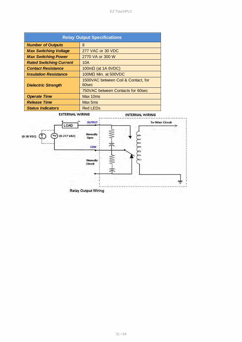
Relay Output Specifications
Number of Outputs 8
Max Switching Voltage 277 VAC or 30 VDC
Max Switching Power 2770 VA or 300 W
Rated Switching Current 10A
Contact Resistance 100mΩ (at 1A 6VDC)
Insulation Resistance 100MΩ Min. at 500VDC
Dielectric Strength 1500VAC between Coil & Contact, for60sec
750VAC between Contacts for 60sec
Operate Time Max 10ms
Release Time Max 5ms
Status Indicators Red LEDs
EZ TouchPLC
32 / 64
Programming the TouchPLC
PLC Operation Sequence
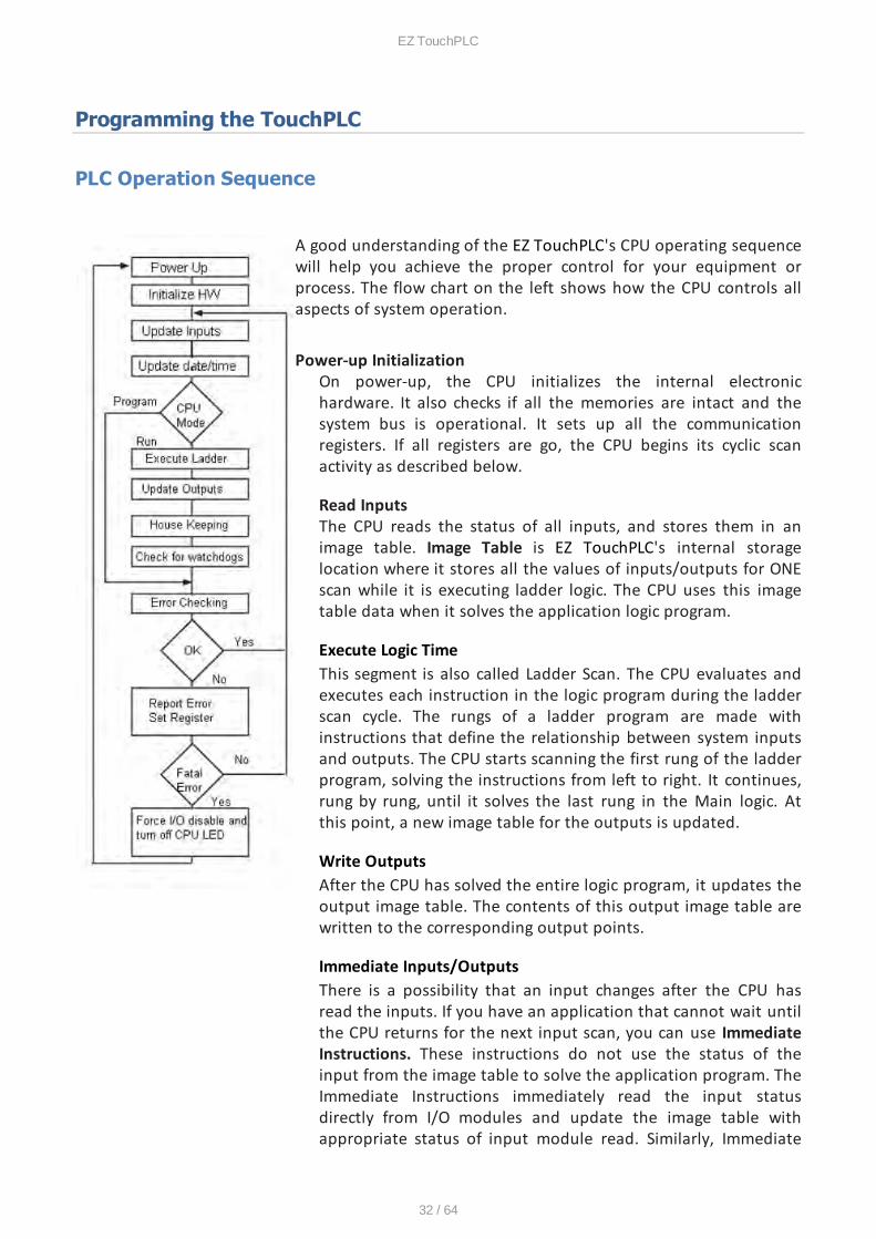
A good understanding of the EZ TouchPLC's CPU operating sequencewill help you achieve the proper control for your equipment orprocess. The flow chart on the left shows how the CPU controls allaspects of system operation.
Power-up InitializationOn power-up, the CPU initializes the internal electronichardware. It also checks if all the memories are intact and thesystem bus is operational. It sets up all the communicationregisters. If all registers are go, the CPU begins its cyclic scanactivity as described below.
Read InputsThe CPU reads the status of all inputs, and stores them in animage table. Image Table is EZ TouchPLC's internal storagelocation where it stores all the values of inputs/outputs for ONEscan while it is executing ladder logic. The CPU uses this imagetable data when it solves the application logic program.
Execute Logic TimeThis segment is also called Ladder Scan. The CPU evaluates andexecutes each instruction in the logic program during the ladderscan cycle. The rungs of a ladder program are made withinstructions that define the relationship between system inputsand outputs. The CPU starts scanning the first rung of the ladderprogram, solving the instructions from left to right. It continues,rung by rung, until it solves the last rung in the Main logic. Atthis point, a new image table for the outputs is updated.
Write OutputsAfter the CPU has solved the entire logic program, it updates theoutput image table. The contents of this output image table arewritten to the corresponding output points.
Immediate Inputs/OutputsThere is a possibility that an input changes after the CPU hasread the inputs. If you have an application that cannot wait untilthe CPU returns for the next input scan, you can use ImmediateInstructions. These instructions do not use the status of theinput from the image table to solve the application program. TheImmediate Instructions immediately read the input statusdirectly from I/O modules and update the image table withappropriate status of input module read. Similarly, Immediate

EZ TouchPLC
33 / 64
Output instructions do not wait for the CPU to complete theladder scan. Immediate outputs are directly written to the imagetable and Outputs are updated accordingly.
SubroutinesThe CPU executes subroutines when called for in the ladderprogram. These subroutines are useful in performing the samelogic operation time and time again just upon one call so you donot have to repeat the rung logic over and over again.
EZ TouchPLC
34 / 64
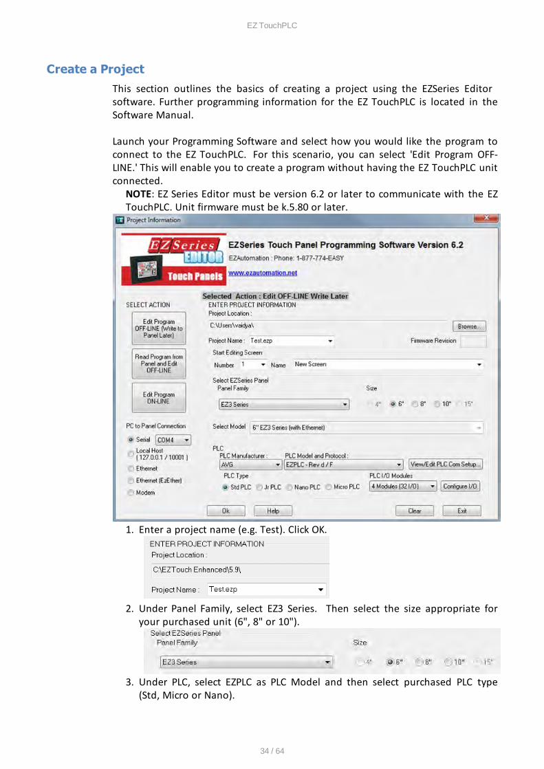
Create a Project
This section outlines the basics of creating a project using the EZSeries Editor software. Further programming information for the EZ TouchPLC is located in theSoftware Manual.
Launch your Programming Software and select how you would like the program toconnect to the EZ TouchPLC. For this scenario, you can select 'Edit Program OFF-LINE.' This will enable you to create a program without having the EZ TouchPLC unitconnected.
NOTE: EZ Series Editor must be version 6.2 or later to communicate with the EZTouchPLC. Unit firmware must be k.5.80 or later.
1. Enter a project name (e.g. Test). Click OK.
2. Under Panel Family, select EZ3 Series. Then select the size appropriate foryour purchased unit (6", 8" or 10").
3. Under PLC, select EZPLC as PLC Model and then select purchased PLC type(Std, Micro or Nano).
EZ TouchPLC
35 / 64
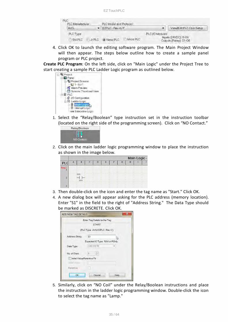
4. Click OK to launch the editing software program. The Main Project Windowwill then appear. The steps below outline how to create a sample panelprogram or PLC project.
Create PLC Program: On the left side, click on "Main Logic" under the Project Tree tostart creating a sample PLC Ladder Logic program as outlined below.
1. Select the “Relay/Boolean” type instruction set in the instruction toolbar(located on the right side of the programming screen). Click on “NO Contact.”
2. Click on the main ladder logic programming window to place the instructionas shown in the image below.
3. Then double-click on the icon and enter the tag name as "Start." Click OK.4. A new dialog box will appear asking for the PLC address (memory location).
Enter "S1" in the field to the right of "Address String." The Data Type shouldbe marked as DISCRETE. Click OK.
5. Similarly, click on “NO Coil” under the Relay/Boolean instructions and placethe instruction in the ladder logic programming window. Double-click the iconto select the tag name as "Lamp."
EZ TouchPLC
36 / 64
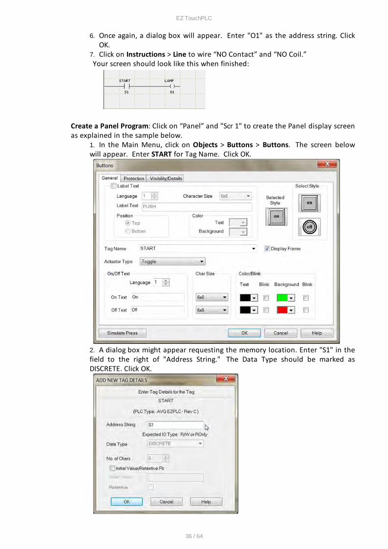
6. Once again, a dialog box will appear. Enter "O1" as the address string. ClickOK.
7. Click on Instructions > Line to wire “NO Contact” and “NO Coil.”Your screen should look like this when finished:
Create a Panel Program: Click on “Panel” and "Scr 1" to create the Panel display screenas explained in the sample below.
1. In the Main Menu, click on Objects > Buttons > Buttons. The screen belowwill appear. Enter START for Tag Name. Click OK.
2. A dialog box might appear requesting the memory location. Enter "S1" in thefield to the right of "Address String." The Data Type should be marked asDISCRETE. Click OK.
EZ TouchPLC
37 / 64
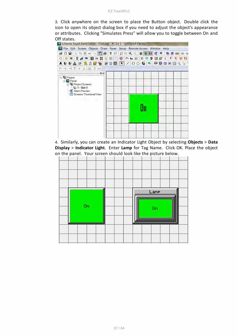
3. Click anywhere on the screen to place the Button object. Double click theicon to open its object dialog box if you need to adjust the object's appearanceor attributes. Clicking "Simulates Press" will allow you to toggle between On andOff states.
4. Similarly, you can create an Indicator Light Object by selecting Objects > DataDisplay > Indicator Light. Enter Lamp for Tag Name. Click OK. Place the objecton the panel. Your screen should look like the picture below.
EZ TouchPLC
38 / 64
Transfer a Project
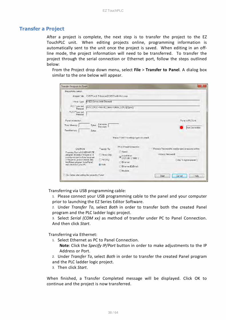
After a project is complete, the next step is to transfer the project to the EZTouchPLC unit. When editing projects online, programming information isautomatically sent to the unit once the project is saved. When editing in an off-line mode, the project information will need to be transferred. To transfer theproject through the serial connection or Ethernet port, follow the steps outlinedbelow:
From the Project drop down menu, select File > Transfer to Panel. A dialog boxsimilar to the one below will appear.
Transferring via USB programming cable:1. Please connect your USB programming cable to the panel and your computerprior to launching the EZ Series Editor Software. 2. Under Transfer To, select Both in order to transfer both the created Panelprogram and the PLC ladder logic project.3. Select Serial (COM xx) as method of transfer under PC to Panel Connection.And then click Start.
Transferring via Ethernet:1. Select Ethernet as PC to Panel Connection.
Note: Click the Specify IP/Port button in order to make adjustments to the IPAddress or Port.
2. Under Transfer To, select Both in order to transfer the created Panel programand the PLC ladder logic project.3. Then click Start.
When finished, a Transfer Completed message will be displayed. Click OK tocontinue and the project is now transferred.
EZ TouchPLC
39 / 64
CPU Memory
Memory Types
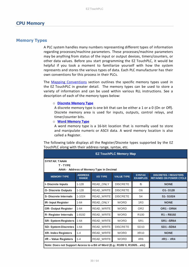
A PLC system handles many numbers representing different types of informationregarding processes/machine parameters. These processes/machine parametersmay be anything from status of the input or output devices, timers/counters, orother data values. Before you start programming the EZ TouchPLC, it would behelpful if you took a moment to familiarize yourself with how the systemrepresents and stores the various types of data. Each PLC manufacturer has theirown conventions for this process in their PLCs.
The Mapping Conventions section outlines the specific memory types used inthe EZ TouchPLC in greater detail. The memory types can be used to store avariety of information and can be used within various RLL instructions. See adescription of each of the memory types below:
o Discrete Memory TypeA discrete memory type is one bit that can be either a 1 or a 0 (On or Off).Discrete memory area is used for inputs, outputs, control relays, andtimer/counter bits.o Word Memory TypeA word memory type is a 16-bit location that is normally used to storeand manipulate numeric or ASCII data. A word memory location is alsocalled a Register.
The following table displays all the Register/Discrete types supported by the EZTouchPLC along with their address range, syntax, etc.
EZ TouchPLC Memory Map
SYNTAX: TAAAA
T - TYPE
AAAA - Address of Memory Type in Decimal
MEMORY TYPEADDRESS
RANGEI/O TYPE VALUE TYPE
SYNTAXEXAMPLES
DISCRETES / REGISTERSRETAINED ON POWER CYCLE
I- Discrete Inputs 1-128 READ_ONLY DISCRETE I5 NONE
O- Discrete Outputs 1-128 READ_WRITE DISCRETE O6 O1- O128
S- Discrete Internals 1-1024 READ_WRITE DISCRETE S4 S1- S1024
IR- Input Register 1-64 READ_ONLY WORD 1R3 NONE
OR- Output Register 1-64 READ_WRITE WORD OR2 OR1 - OR64
R- Register Internals 1-8192 READ_WRITE WORD R100 R1 – R8192
SR- System Registers 1-64 READ_WRITE WORD SR1 SR1 –SR64
SD- System Discretes 1-64 READ_WRITE DISCRETE SD10 SD1 –SD64
XR- Index Registers 1-4 READ_WRITE WORD XR10 NONE
#R – Value Registers 1-4 READ_WRITE WORD #R6 #R1 - #R4
Note: Does not Support Access to a Bit of Word (E.g.: R100/ 0, R100/5…etc)
EZ TouchPLC
40 / 64
Please Note: Since the PLC Editor is a common programming platform for all themodels offered by the AVG PLC family, it may allow you to include 128 Inputs (I),128 Output (O), 64 input Registers (IR) and 64 Output Registers (OR) in the mainlogic. However, the TouchPLC Micro only physically supports 24 discrete inputsand 16 discrete outputs; hence it is recommended that you only use I1-I24 andO1-O16 while programming the Micro. Similarly, the TouchPLC Nano onlyphysically supports 16 inputs and 8 outputs; hence it is recommended that youonly use I1-I16 and O1-O8 while programming the Nano. The remaining O bitsmay be used as "Scratch bits." Similarly, only IR1-IR4 and OR1-OR4 should beused to address the I/O Registers, while the rest of the Output Registers may beused as "Scratch Registers." Although there are 64 System Registers (SR) and 64System Discretes (SD) available in the programming software, many of them arepreassigned a function.
Mapping Conventions
Discrete Inputs/Outputs
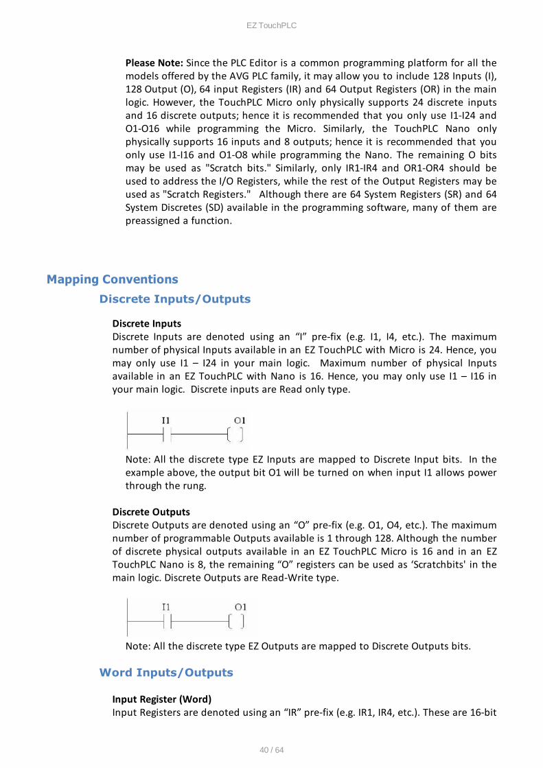
Discrete InputsDiscrete Inputs are denoted using an “I” pre-fix (e.g. I1, I4, etc.). The maximumnumber of physical Inputs available in an EZ TouchPLC with Micro is 24. Hence, youmay only use I1 – I24 in your main logic. Maximum number of physical Inputsavailable in an EZ TouchPLC with Nano is 16. Hence, you may only use I1 – I16 inyour main logic. Discrete inputs are Read only type.
Note: All the discrete type EZ Inputs are mapped to Discrete Input bits. In theexample above, the output bit O1 will be turned on when input I1 allows powerthrough the rung.
Discrete OutputsDiscrete Outputs are denoted using an “O” pre-fix (e.g. O1, O4, etc.). The maximumnumber of programmable Outputs available is 1 through 128. Although the numberof discrete physical outputs available in an EZ TouchPLC Micro is 16 and in an EZTouchPLC Nano is 8, the remaining “O” registers can be used as ‘Scratchbits' in themain logic. Discrete Outputs are Read-Write type.
Note: All the discrete type EZ Outputs are mapped to Discrete Outputs bits.
Word Inputs/Outputs
Input Register (Word)Input Registers are denoted using an “IR” pre-fix (e.g. IR1, IR4, etc.). These are 16-bit
EZ TouchPLC
41 / 64
Word data types (registers). The maximum number of Input Registers available is 1through 64. The EZ TouchPLC with Micro only requires registers IR1-IR4. You canonly Read from an IR register.
Note: All the EZ Analog Inputs (if available) are mapped to Input Registers.
Output Register (Word)Output Registers are denoted using an “OR” pre-fix (e.g. OR1, OR4, etc.). These are16-bit Word data types. The maximum number of Output Registers available is 1through 64. The EZ TouchPLC with Micro uses OR1-OR4 to connect to physicalAnalog Outputs. OR are Read-Write type of Word registers.
Note: All the EZ Analog Outputs (if available) are mapped to Output Registers.
Internals
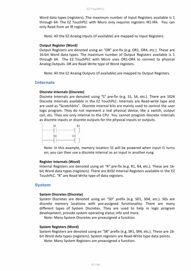
Discrete Internals (Discrete)Discrete Internals are denoted using “S” pre-fix (e.g. S1, S4, etc.). There are 1024Discrete Internals available in the EZ TouchPLC. Internals are Read-write type andare used as “Scratchbits”. Discrete internal bits are mainly used to control the userlogic program. They do not represent a real physical device, like a switch, outputcoil, etc. They are only internal to the CPU. You cannot program discrete internalsas discrete inputs or discrete outputs for the physical inputs or outputs.
Note: In this example, memory location S1 will be powered when input I1 turnson; you can then use a discrete internal as an input in another rung.
Register Internals (Word)Internal Registers are denoted using an “R” pre-fix (e.g. R1, R4, etc.). These are 16-bit Word data types (registers). There are 8192 Internal Registers available in the EZTouchPLC. "R" are Read-Write type of data registers.
System
System Discretes (Discrete)System Discretes are denoted using an “SD” prefix (e.g. SD1, SD4, etc.). SDs arediscrete memory locations with pre-assigned functionality. There are manydifferent types of System Discretes. They are used to help in logic programdevelopment, provide system operating status info and more.
Note: Many System Discretes are preassigned a function.
System Registers (Word)System Registers are denoted using an “SR” prefix (e.g. SR1, SR4, etc.). These are 16-bit Word data types (registers). System registers are Read-Write type data points.
Note: Many System Registers are preassigned a function.

EZ TouchPLC
42 / 64
Index and Value Registers (Word)
The Index Register data type is represented by an “XR” prefix (e.g. XR1, XR2 etc.).There are 4 XR memory locations available in EZ TouchPLC. “XR” is a Read-Writedata type and it is mainly used to point to the correct address of “R” registers. Thepointed-to “R” registers data value is stored in “#R” registers.
Value Register data type is represented by a “#R” prefix (e.g. #R1, #R2 etc.). Thereare 4 #R memory locations available in EZ TouchPLC. “#R” is a Read-Write data typeand it is mainly used to read/write value of “R” registers as pointed out by “XR”registers.
Both XR and #R registers are used in conjunction with each other and provide aconvenient way of addressing R registers.
Example:Let's assume data values: R59=9874, R8000=32
If XR1=59Then #R1=9874 (the actual data value of R59)If XR2=8000Then #R2=32 (the actual data value of R8000)
XR contains the address of the operand (or specifies a register that contains theeffective address), #R is used to read or write the actual operand. Indirectaddressing is often combined with pre- or post-increment (or decrement)addressing. This allows the address of the operand to be increased or decreased bythe specified number either before or after using it. Proper usage of XR variablesoften saves a lot of programming.
EZ TouchPLC
43 / 64
Additional Features
Data Logging Overview
The EZ TouchPLC offers a flexible Data Acquisition capability. You can acquire and savethe data for one or more tags defined in the panel. The acquired data along with atime stamp is saved in CSV file format in the USB stick or the MicroSD card, dependingon how the schedule is set.
Schedules determine the way data will be collected. For example, data can becollected every 10 seconds, or simply at a specific time such as 9 AM, or when acertain event takes place. The user can define one or more schedules as long as eachschedule is unique. (For example, there cannot be two schedules that each collectdata every 30 seconds.) User can also associate a name (up to 8 characters) with eachschedule. Each schedule can be used to collect data for up to 32 tags.
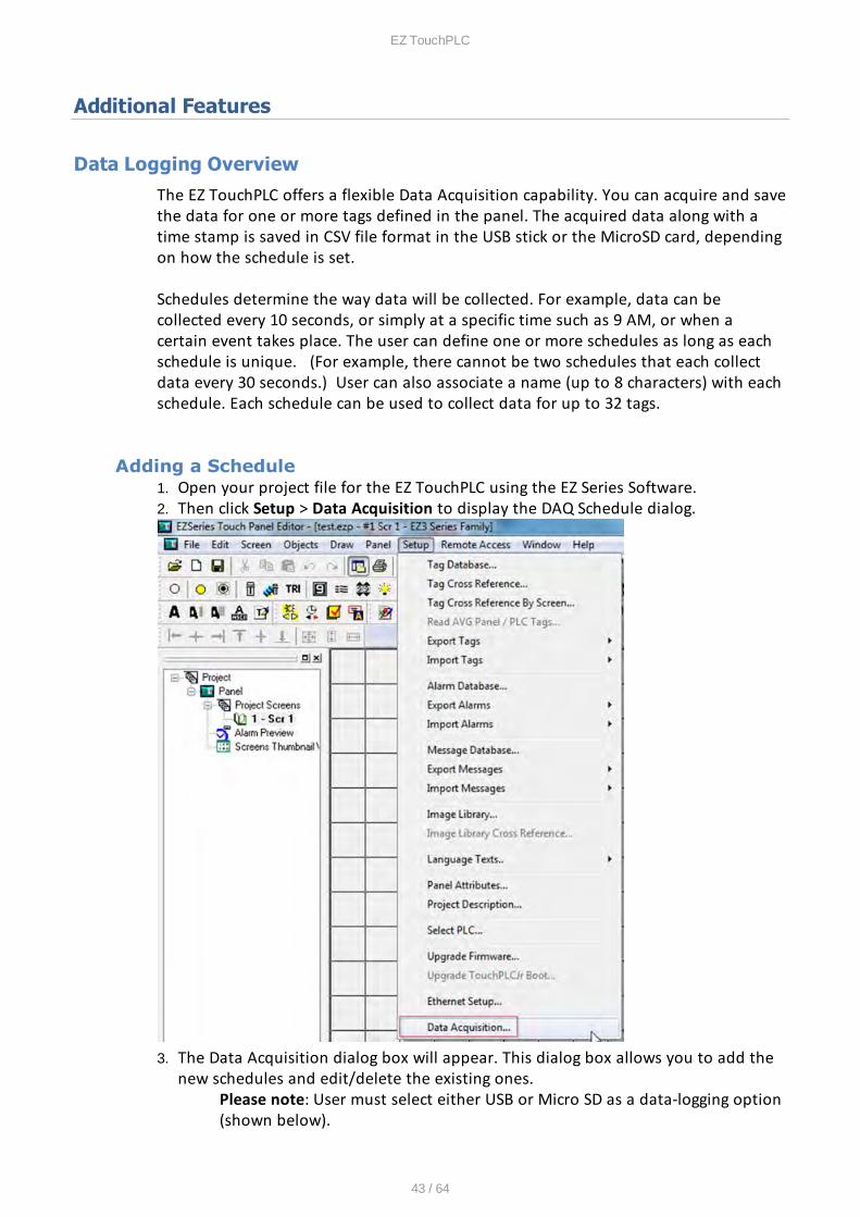
Adding a Schedule1. Open your project file for the EZ TouchPLC using the EZ Series Software.2. Then click Setup > Data Acquisition to display the DAQ Schedule dialog.
3. The Data Acquisition dialog box will appear. This dialog box allows you to add thenew schedules and edit/delete the existing ones.
Please note: User must select either USB or Micro SD as a data-logging option(shown below).
EZ TouchPLC
44 / 64
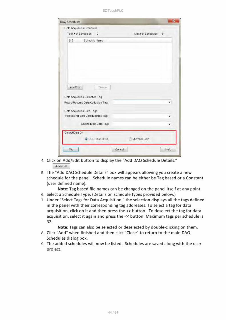
4. Click on Add/Edit buton to display the ““dd D“A Schedule Details.”
5. The "Add DAQ Schedule Details" box will appears allowing you create a newschedule for the panel. Schedule names can be either be Tag based or a Constant(user defined name).
Note: Tag based file names can be changed on the panel itself at any point.6. Select a Schedule Type. (Details on schedule types provided below.)7. Under "Select Tags for Data Acquisition," the selection displays all the tags defined
in the panel with their corresponding tag addresses. To select a tag for dataacquisition, click on it and then press the >> button. To deselect the tag for dataacquisition, select it again and press the << button. Maximum tags per schedule is32.
Note: Tags can also be selected or deselected by double-clicking on them.8. Click "Add" when finished and then click "Close" to return to the main DAQ
Schedules dialog box.9. The added schedules will now be listed. Schedules are saved along with the user
project.
EZ TouchPLC
45 / 64
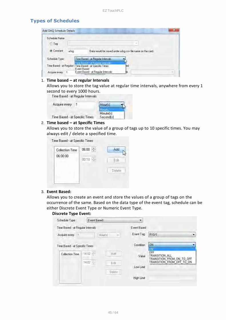
Types of Schedules
1. Time based – at regular IntervalsAllows you to store the tag value at regular time intervals, anywhere from every 1second to every 1000 hours.
2. Time based – at Specifc TimesAllows you to store the value of a group of tags up to 10 specific times. You mayalways edit / delete a specified time.
3. Event Based: Allows you to create an event and store the values of a group of tags on theoccurrence of the same. Based on the data type of the event tag, schedule can beeither Discrete Event Type or Numeric Event Type.
Discrete Type Event:
EZ TouchPLC
46 / 64
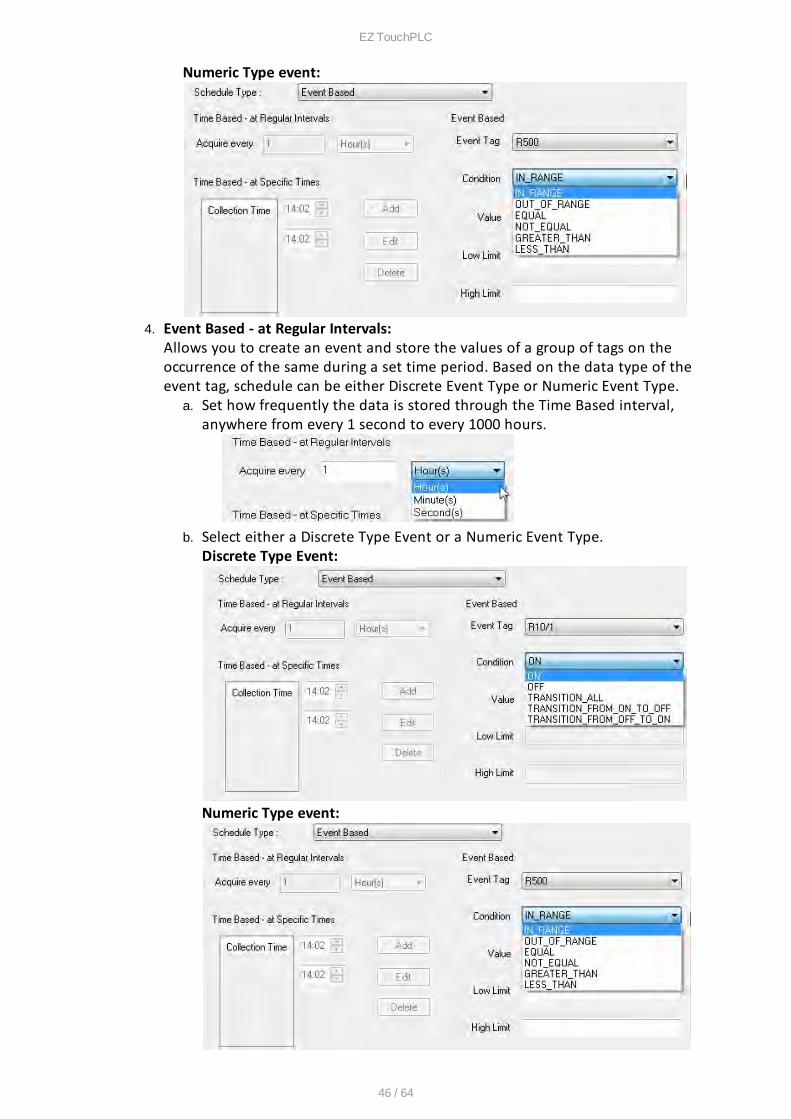
Numeric Type event:
4. Event Based - at Regular Intervals: Allows you to create an event and store the values of a group of tags on theoccurrence of the same during a set time period. Based on the data type of theevent tag, schedule can be either Discrete Event Type or Numeric Event Type.
a. Set how frequently the data is stored through the Time Based interval,anywhere from every 1 second to every 1000 hours.
b. Select either a Discrete Type Event or a Numeric Event Type.Discrete Type Event:
Numeric Type event:
EZ TouchPLC
47 / 64
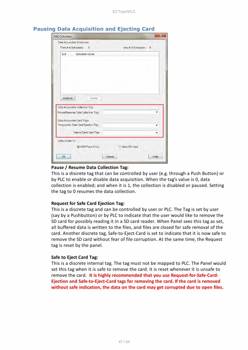
Pausing Data Acquisition and Ejecting Card
Pause / Resume Data Collection Tag: This is a discrete tag that can be controlled by user (e.g. through a Push Button) orby PLC to enable or disable data acquisition. When the tag's value is 0, datacollection is enabled; and when it is 1, the collection is disabled or paused. Settingthe tag to 0 resumes the data collection.
Request for Safe Card Ejection Tag: This is a discrete tag and can be controlled by user or PLC. The Tag is set by user(say by a Pushbutton) or by PLC to indicate that the user would like to remove theSD card for possibly reading it in a SD card reader. When Panel sees this tag as set,all buffered data is written to the files, and files are closed for safe removal of thecard. Another discrete tag, Safe-to-Eject-Card is set to indicate that it is now safe toremove the SD card without fear of file corruption. At the same time, the Requesttag is reset by the panel.
Safe to Eject Card Tag: This is a discrete internal tag. The tag must not be mapped to PLC. The Panel wouldset this tag when it is safe to remove the card. It is reset whenever it is unsafe toremove the card. It is highly recommended that you use Request-for-Safe-Card-Ejection and Safe-to-Eject-Card tags for removing the card. If the card is removedwithout safe indication, the data on the card may get corrupted due to open files.
EZ TouchPLC
48 / 64
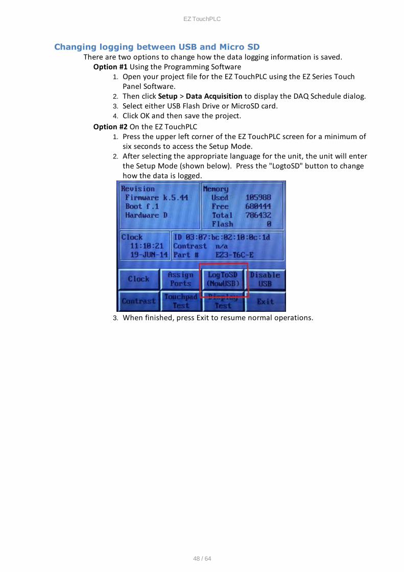
Changing logging between USB and Micro SDThere are two options to change how the data logging information is saved.
Option #1 Using the Programming Software1. Open your project file for the EZ TouchPLC using the EZ Series Touch
Panel Software.2. Then click Setup > Data Acquisition to display the DAQ Schedule dialog.3. Select either USB Flash Drive or MicroSD card. 4. Click OK and then save the project.
Option #2 On the EZ TouchPLC1. Press the upper left corner of the EZ TouchPLC screen for a minimum of
six seconds to access the Setup Mode.2. After selecting the appropriate language for the unit, the unit will enter
the Setup Mode (shown below). Press the "LogtoSD" button to changehow the data is logged.
3. When finished, press Exit to resume normal operations.
EZ TouchPLC
49 / 64
Create OEM Packager
The EZPackager utility allows an OEM to distribute updates to EZSeries Touch Panel orEZPLC projects easily and quickly. Using the utility, OEMs can package current projectand/or firmware into a zip file for distribution to the end user via email or the web. Ifyou click on File > Create OEM Package, it will allow you to package the current EZPanelor EZPLC project and/or the firmware into a zip file called a pack file for the distributionpurposes.Benefits of the utility include:
• OEMs save costs associated with the distribution of panel updates in thefield (sending field service personnel or mailing CDs).
• OEM Projects are protected since end users cannot modify the projects.• The end user benefits from convenient, fast and easy updates without
needing to purchase the EZSeries Touch Panel Editor software.
Creating a Pack File:
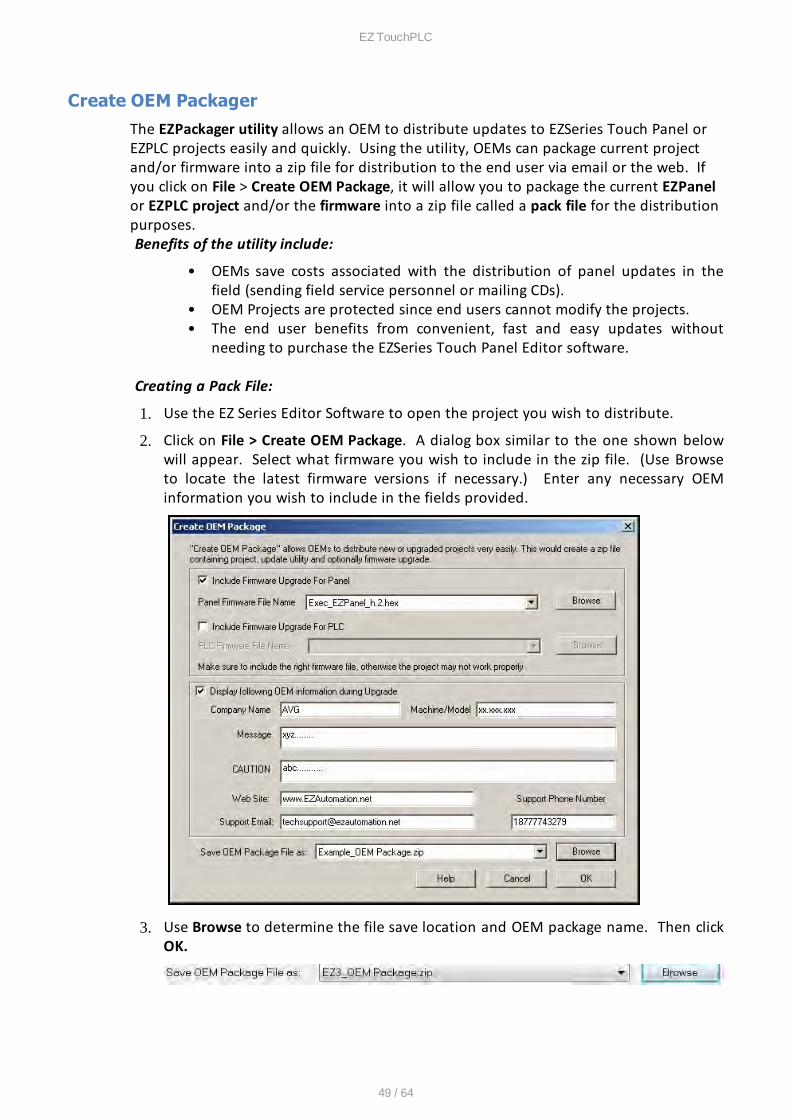
1. Use the EZ Series Editor Software to open the project you wish to distribute.
2. Click on File > Create OEM Package. A dialog box similar to the one shown belowwill appear. Select what firmware you wish to include in the zip file. (Use Browseto locate the latest firmware versions if necessary.) Enter any necessary OEMinformation you wish to include in the fields provided.
3. Use Browse to determine the file save location and OEM package name. Then clickOK.
EZ TouchPLC
50 / 64
Opening a Pack FileA Pack File contains the following:
1. Updater application (comprising of the .exe and required dlls)2. Project files (which would show up inside the Project folder when unzipped)3. Firmware files (which would show up inside the Firmware folder when unzipped
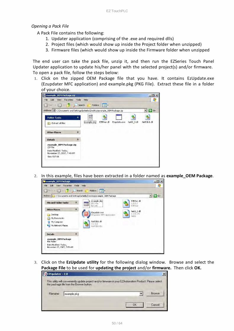
The end user can take the pack file, unzip it, and then run the EZSeries Touch PanelUpdater application to update his/her panel with the selected project(s) and/or firmware. To open a pack file, follow the steps below:1. Click on the zipped OEM Package file that you have. It contains EzUpdate.exe
(Ezupdater MFC application) and example.pkg (PKG File). Extract these file in a folderof your choice.
2. In this example, files have been extracted in a folder named as example_OEM Package.
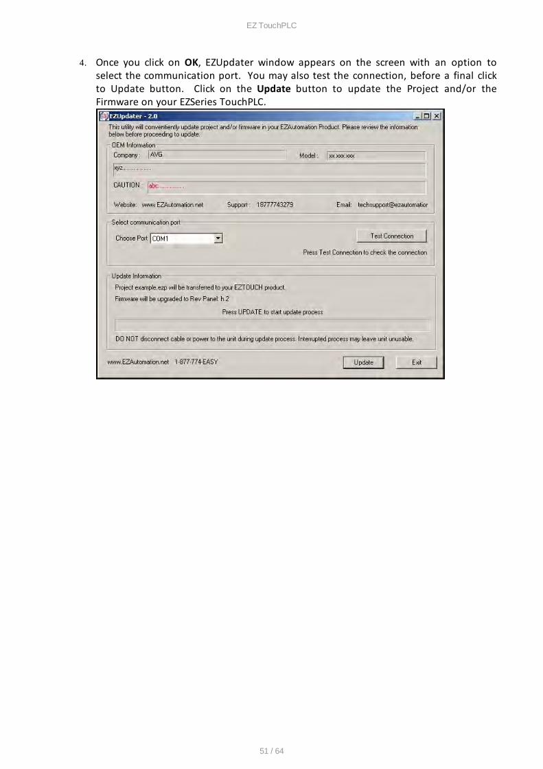
3. Click on the EzUpdate utility for the following dialog window. Browse and select thePackage File to be used for updating the project and/or firmware. Then click OK.
EZ TouchPLC
51 / 64
4. Once you click on OK, EZUpdater window appears on the screen with an option toselect the communication port. You may also test the connection, before a final clickto Update button. Click on the Update button to update the Project and/or theFirmware on your EZSeries TouchPLC.
EZ TouchPLC
52 / 64
Create USB Loader
Through the EZ Series Editor Software (version 5.5 and higher) users can program EZTouchPLCs through a USB Flash drive. This process especially benefits SystemIntegrators and OEMs with upgrading the Panels on-site without having to actuallyconnect to a computer. Since multiple programs can be saved on one USB Flash drive,the user can program different panels with the same USB Flash drive, or quicklychange the Panel for different jobs.The EZ TouchPLCs can be programmed in following easy steps:
1. Create a USB file (*.hmi) using the EZ Touch Program Loader.2. Save the file on the USB Flash drive (only in the root directory).3. Insert the USB stick into the EZ TouchPLC's USB port.4. The panel brings up a list of projects that are available on the USB Flash
drive. Select the necessary project and press OK. (If the panel is notcompatible with the project selected, an Error message is displayed.)
5. The project is automatically loaded on the EZ TouchPLC.
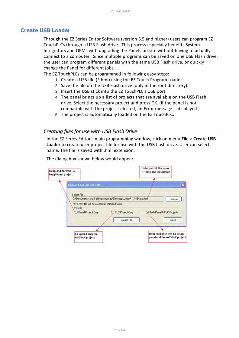
Creating files for use with USB Flash DriveIn the EZ Series Editor's main programming window, click on menu File > Create USBLoader to create user project file for use with the USB flash drive. User can selectname. The file is saved with .hmi extension.
The dialog box shown below would appear:
EZ TouchPLC
53 / 64
Copy file(s) on USB DriveCopy file(s) created by the editor on the root directory of a USB flash disk.(Please note files copied in a location other than root directory would not beread by the panel.) All files are saved automatically with .hmi extension. Fileswithout this extension will not be read.
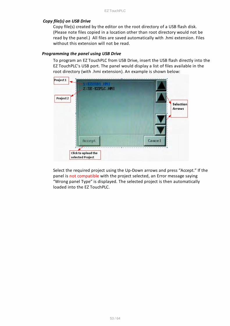
Programming the panel using USB DriveTo program an EZ TouchPLC from USB Drive, insert the USB flash directly into theEZ TouchPLC's USB port. The panel would display a list of files available in theroot directory (with .hmi extension). An example is shown below:
Select the required project using the Up-Down arrows and press ““ccept.” If thepanel is not compatible with the project selected, an Error message saying“Wrong panel Type” is displayed. The selected project is then automaticallyloaded into the EZ TouchPLC.
EZ TouchPLC
54 / 64
Remote Monitoring & Control
With the introduction of new Remote-Access Card and Remote Monitor & Control(RMC) Software EZSeries TouchPLCs offer a unique set of remote capabilities. A usercan remotely log on to a unit and monitor any of the panel screens with live dataincluding the currently displayed screen.
With the right access permissions and authentication, a user can remotely “touch”the objects on the panel, to control a machine/plant effectively. Remote controlfeature can be invaluable for remote diagnostics, unmanned operations, orsupervisory monitoring.
In addition to remote monitoring and control, user may also program the panelsremotely over Ethernet, allowing OEMs to remotely upgrade the screen programswithin the panels.
For Remote Monitoring and control we need to follow these steps:1. Use EZ Touch Panel editor to set up IP address of the panel.2. Use EZ Touch Panel editor to set up remote users and authentication level.3. Use RMC (Remote Monitoring & Control) software to connect to the panel
remotely.
Setting up Remote Users
The EZ-RMC Software can be used with or without defining authorized users. If youdon't define any remote users, then anyone can connect to the panel using EZ-RMCSoftware. However they can ONLY VIEW the panel screen; they would not be able tomake any changes to the panel. It is highly recommended that you do defineauthorized users for remote access.
Remote users can be given View ONLY or Operation (View + Control) permission.View only permission allows user to ONLY monitor the panel display remotely, whileoperation permission allows a user to operate panel remotely.
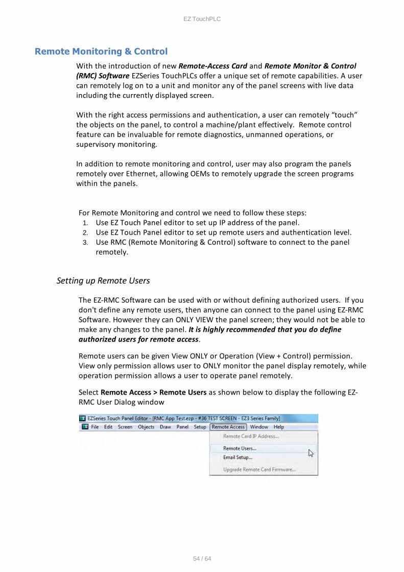
Select Remote Access > Remote Users as shown below to display the following EZ-RMC User Dialog window
EZ TouchPLC
55 / 64
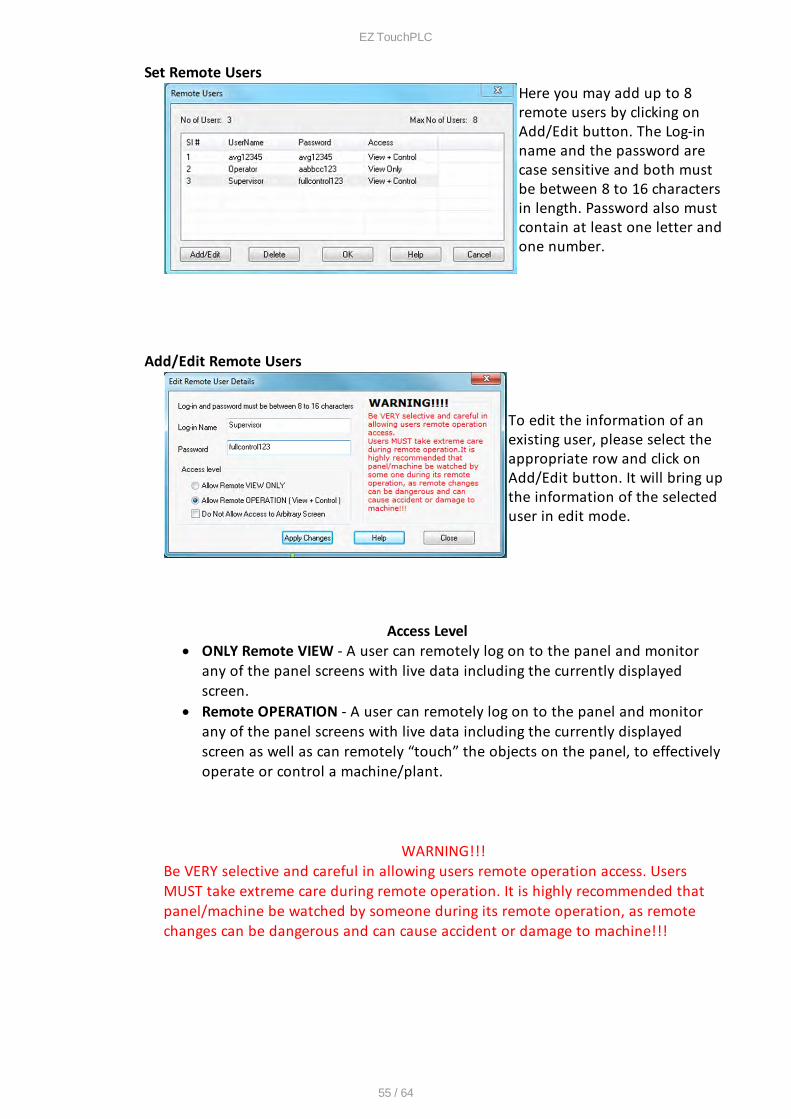
Set Remote UsersHere you may add up to 8remote users by clicking onAdd/Edit button. The Log-inname and the password arecase sensitive and both mustbe between 8 to 16 charactersin length. Password also mustcontain at least one letter andone number.
Add/Edit Remote Users
To edit the information of anexisting user, please select theappropriate row and click onAdd/Edit button. It will bring upthe information of the selecteduser in edit mode.
Access Level · ONLY Remote VIEW - A user can remotely log on to the panel and monitor
any of the panel screens with live data including the currently displayedscreen.
· Remote OPERATION - A user can remotely log on to the panel and monitorany of the panel screens with live data including the currently displayedscreen as well as can remotely “touch” the objects on the panel, to effectivelyoperate or control a machine/plant.
WARNING!!!Be VERY selective and careful in allowing users remote operation access. UsersMUST take extreme care during remote operation. It is highly recommended thatpanel/machine be watched by someone during its remote operation, as remotechanges can be dangerous and can cause accident or damage to machine!!!
EZ TouchPLC
56 / 64
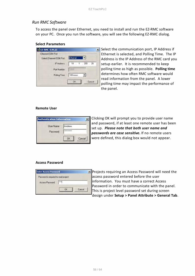
Run RMC SoftwareTo access the panel over Ethernet, you need to install and run the EZ-RMC softwareon your PC. Once you run the software, you will see the following EZ-RMC dialog.
Select Parameters Select the communication port, IP Address ifEthernet is selected, and Polling Time. The IPAddress is the IP Address of the RMC card yousetup earlier. It is recommended to keeppolling time as high as possible. Polling timedetermines how often RMC software wouldread information from the panel. A lowerpolling time may impact the performance ofthe panel.
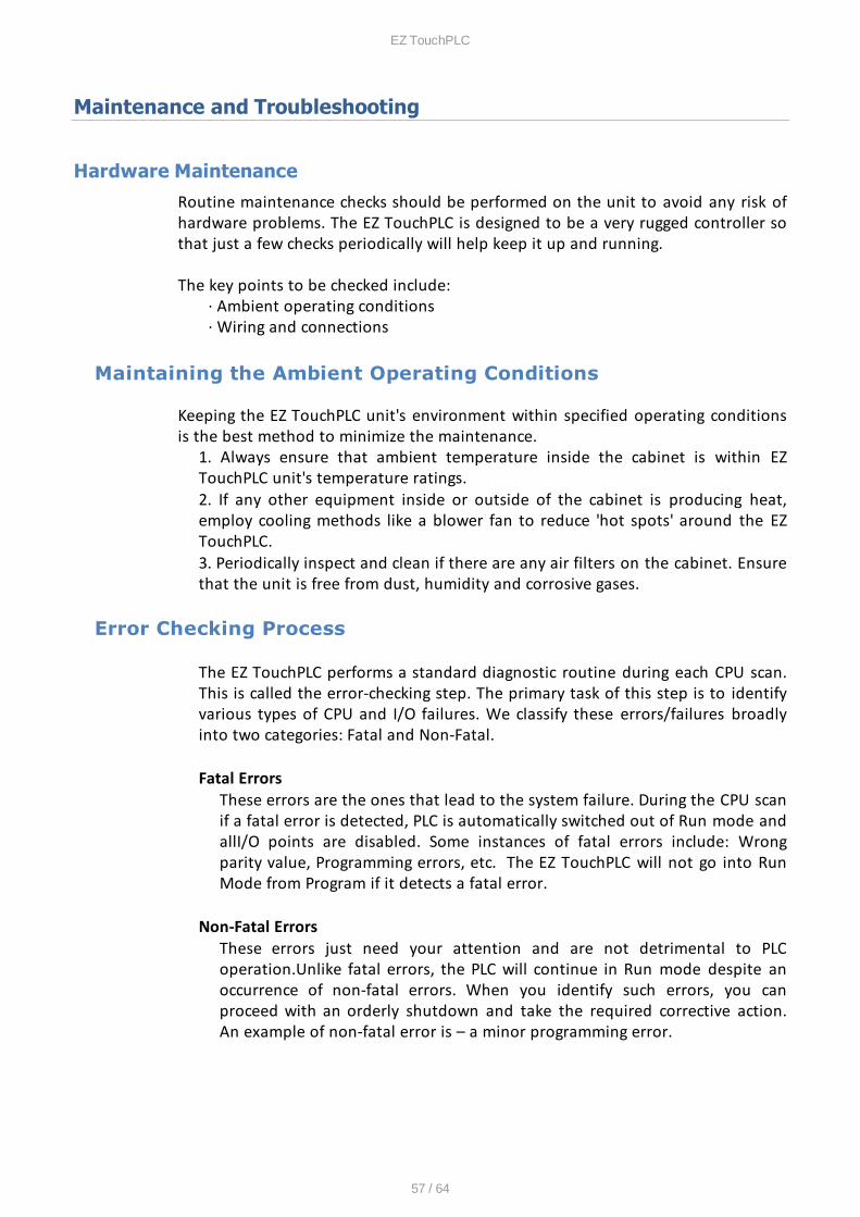
Remote User
Clicking OK will prompt you to provide user nameand password, if at least one remote user has beenset up. Please note that both user name andpasswords are case sensitive. If no remote userswere defined, this dialog box would not appear.
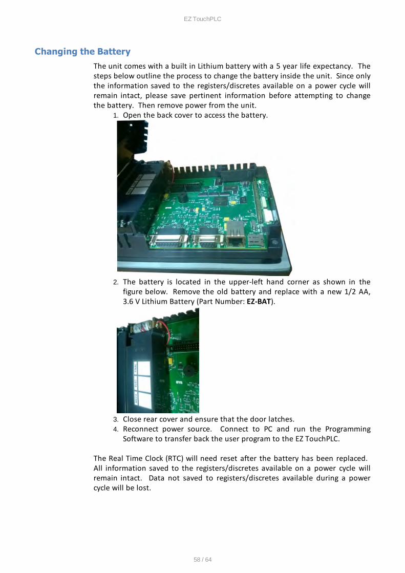
Access Password
Projects requiring an Access Password will need theaccess password entered before the userinformation. You must have a correct AccessPassword in order to communicate with the panel. This is project level password set during screendesign under Setup > Panel Attribute > General Tab.
EZ TouchPLC
57 / 64
Maintenance and Troubleshooting
Hardware Maintenance
Routine maintenance checks should be performed on the unit to avoid any risk ofhardware problems. The EZ TouchPLC is designed to be a very rugged controller sothat just a few checks periodically will help keep it up and running.
The key points to be checked include: · Ambient operating conditions · Wiring and connections
Maintaining the Ambient Operating Conditions
Keeping the EZ TouchPLC unit's environment within specified operating conditionsis the best method to minimize the maintenance.
1. Always ensure that ambient temperature inside the cabinet is within EZTouchPLC unit's temperature ratings.2. If any other equipment inside or outside of the cabinet is producing heat,employ cooling methods like a blower fan to reduce 'hot spots' around the EZTouchPLC.3. Periodically inspect and clean if there are any air filters on the cabinet. Ensurethat the unit is free from dust, humidity and corrosive gases.
Error Checking Process
The EZ TouchPLC performs a standard diagnostic routine during each CPU scan.This is called the error-checking step. The primary task of this step is to identifyvarious types of CPU and I/O failures. We classify these errors/failures broadlyinto two categories: Fatal and Non-Fatal.
Fatal ErrorsThese errors are the ones that lead to the system failure. During the CPU scanif a fatal error is detected, PLC is automatically switched out of Run mode andallI/O points are disabled. Some instances of fatal errors include: Wrongparity value, Programming errors, etc. The EZ TouchPLC will not go into RunMode from Program if it detects a fatal error.
Non-Fatal ErrorsThese errors just need your attention and are not detrimental to PLCoperation.Unlike fatal errors, the PLC will continue in Run mode despite anoccurrence of non-fatal errors. When you identify such errors, you canproceed with an orderly shutdown and take the required corrective action.An example of non-fatal error is – a minor programming error.
EZ TouchPLC
58 / 64
Changing the Battery
The unit comes with a built in Lithium battery with a 5 year life expectancy. Thesteps below outline the process to change the battery inside the unit. Since onlythe information saved to the registers/discretes available on a power cycle willremain intact, please save pertinent information before attempting to changethe battery. Then remove power from the unit.
1. Open the back cover to access the battery.
2. The battery is located in the upper-left hand corner as shown in thefigure below. Remove the old battery and replace with a new 1/2 AA,3.6 V Lithium Battery (Part Number: EZ-BAT).
3. Close rear cover and ensure that the door latches.4. Reconnect power source. Connect to PC and run the Programming
Software to transfer back the user program to the EZ TouchPLC.
The Real Time Clock (RTC) will need reset after the battery has been replaced. All information saved to the registers/discretes available on a power cycle willremain intact. Data not saved to registers/discretes available during a powercycle will be lost.

EZ TouchPLC
59 / 64
Update Firmware
There are several methods to update the firmware for an EZ TouchPLC unit. Previously, it was explained how to update firmware through an OEM Packager file. Alternatively, the user can follow the steps below to update firmware through theEZ Series Software and a COM port on the EZ TouchPLC unit.
NOTE: A firmware upgrade will wipe out the existing project in the unit; it isalways advised to take a backup of the project before firmware upgrade process.
1. Insert the EZ-PGMCBL programming cable into the COM1 port. Then launchthe EZ Panel Editor software.
2. Select Edit Program OFFLINE and enter a project name (e.g. Test). Click OK.
3. Under Panel Family, select EZ3 Series. Then select the size appropriate foryour purchased unit (6", 8" or 10").
4. Under PLC, select EZPLC as PLC Model and then select purchased PLC type(Std, Micro or Nano).
5. After the project loads, click Setup > Upgrade Firmware. A dialog box willappear requesting the firmware file you would like to load to the unit.
EZ TouchPLC
60 / 64
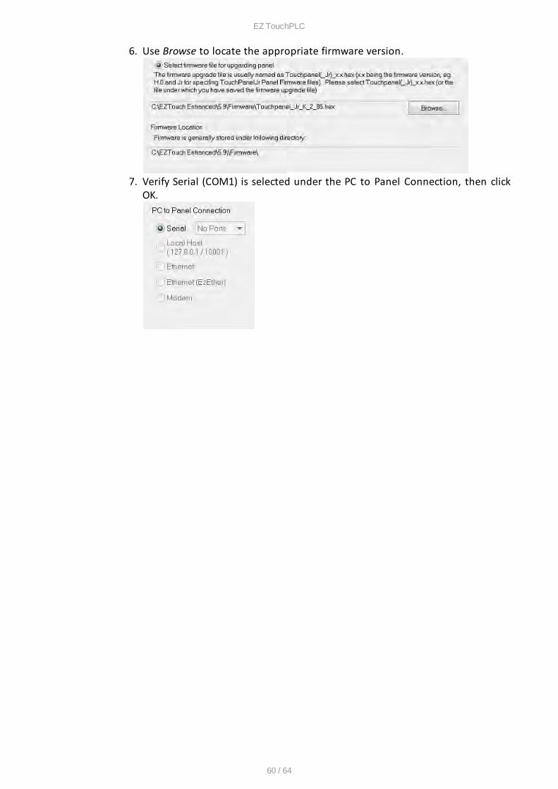
6. Use Browse to locate the appropriate firmware version.
7. Verify Serial (COM1) is selected under the PC to Panel Connection, then clickOK.
EZ TouchPLC
61 / 64
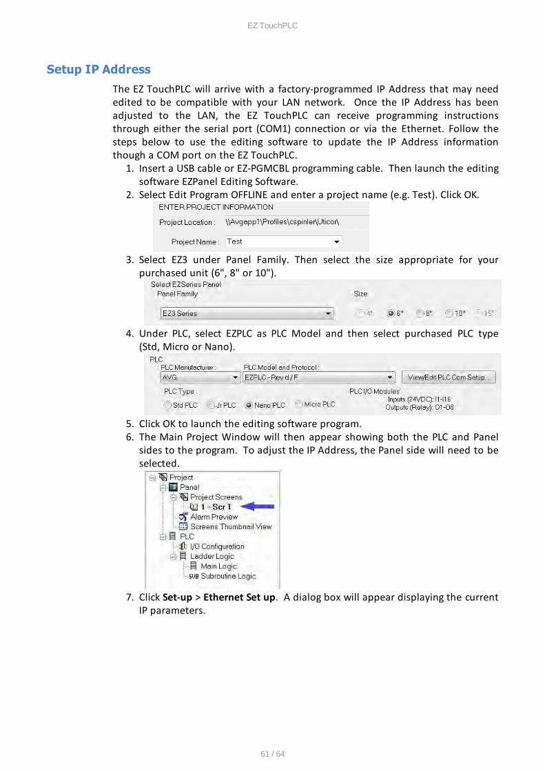
Setup IP Address
The EZ TouchPLC will arrive with a factory-programmed IP Address that may neededited to be compatible with your LAN network. Once the IP Address has beenadjusted to the LAN, the EZ TouchPLC can receive programming instructionsthrough either the serial port (COM1) connection or via the Ethernet. Follow thesteps below to use the editing software to update the IP Address informationthough a COM port on the EZ TouchPLC.
1. Insert a USB cable or EZ-PGMCBL programming cable. Then launch the editingsoftware EZPanel Editing Software.
2. Select Edit Program OFFLINE and enter a project name (e.g. Test). Click OK.
3. Select EZ3 under Panel Family. Then select the size appropriate for yourpurchased unit (6", 8" or 10").
4. Under PLC, select EZPLC as PLC Model and then select purchased PLC type(Std, Micro or Nano).
5. Click OK to launch the editing software program. 6. The Main Project Window will then appear showing both the PLC and Panel
sides to the program. To adjust the IP Address, the Panel side will need to beselected.
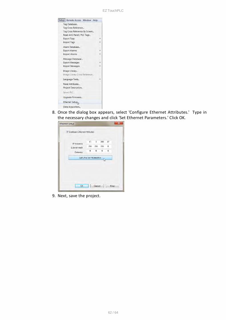
7. Click Set-up > Ethernet Set up. A dialog box will appear displaying the currentIP parameters.
EZ TouchPLC
62 / 64
8. Once the dialog box appears, select 'Configure Ethernet Attributes.' Type inthe necessary changes and click 'Set Ethernet Parameters.' Click OK.
9. Next, save the project.

EZ TouchPLC
63 / 64
Troubleshooting
If you encounter difficulties while using the EZ TouchPLC device, please consult the listbelow which outlines common troubleshooting issues and their solutions. Additionalassistance is also available within the EZ Panel Enhanced Software Help. Alternatively, youmay also find answers to your questions in the operator interface section of our website @ flash.ezautomation.net.
Issue: Panel won't power upSolution: Apply power and observe the LED in the back of the panel
a) LED does not turn on: No power to the unit or power supply failed, check thepower supply.b) LED turns RED and stays RED: Unit has failed, Please return the panel for repair.c) LED flashes RED and turns GREEN: Unit is OK, Display might have gone bad. Returnpanel for repair.
Issue: Can't program the unit using USB Programming cableSolution: Disconnect and then reconnect the programming cable
Please unplug the USB programming cable from the computer and close theprogramming software. Plug the USB cable back in, wait for 10 – 15 seconds and launch the Programmingsoftware.Our programming software reads the com ports directly from the device manager ofthe computer and it has auto detect feature.
Issue: USB Flash drive is not recognizedSolution: Using a different USB Flash drive, ensure the USB function is enabled
Using a low memory capacity USB Flash drive, preferably less than 2 GB, press andhold the upper left corner of the Touch screen for about 6 seconds to reach the Setupmenu on the panel. Click on English. Check the 2 pre-programmed buttons to ensureUSB is enabled and “Log to SD (Now USB)” buton is enabled. Restart / power cycleyour panel.
Issue: Touch cells not respondingSolution: Initiate a TouchPad Test
Press and hold the upper left corner of the Touch screen for about 6 seconds to reachthe Setup menu on the panel. Click on English. Click on the Touchpad Test button andpress all Touch cells to see if it responds to Touch. If all buttons respond, then there isno problem with the Touch screen. If some or all of the touch cells don't respond totouch, then the unit needs to come back to the factory for repair.
Issue: Ethernet not respondingSolution: Set the IP Address
1. Please set the IP address for the panel using our programming software and goingto Setup > Ethernet Setup.
a. Please match the first 3 octets of the IP address to your network and alsoenter subnet mask.
b. If your network has a gateway, then enter the gateway address.2. Please use a straight Ethernet cable and connect it through a hub.
EZ TouchPLC
64 / 64
3. Power cycle the panel and ping the IP address assigned to the panel by going toyour command prompt.
a. If it is pinging, disconnect the cable from the panel end and ping again, if itpings again, then there is another device with the same IP address in thenetwork.
b. If it does not ping, then there is no duplicate device. Connecting theEthernet cable back to the panel should resume communications.
4. If it is still not communicating, please restart your panel and during boot up checkif the MAC ID is present. If it is not there then you will have to reset the MACaddress. Please call EZ Automation Tech support for help.
Issue: Incorrect Communication Packet (Time Out Error) Check cable and communicationportSolution: Check cable and communication port
First, make sure you are using an EZ-PGMCBL. A standard RS-232 cable will not work.Next, check if the software / firmware incompatibility exists. Also check if you haveselected the appropriate computer COM port to transfer the program in the panelprogramming software or see if there are any third party programs which might beusing the communication port of your computer.
Issue: Selected panel does not match the connected panel, write to panel is abortedSolution: Correct panel type
When writing/transferring the project to the panel, the panel type selected on thescreen "Step 1: Project Information" must match the panel that the computer and PLCare physically connected to or the program loader will not upload the project. Exitthe OFF-LINE Editor to the "Step 1: Project Information" screen, and select theappropriate panel type and size of the connected panel and try transferring theproject to the panel.
Issue: Unable to open communication portSolution: Change communication ports
Select a different communication port in the programming software to transfer theproject.
Still Need Help?Technical SupportMost of the frequently encountered problems regarding the EZ TouchPLC unit'soperation are answered in the sections above. However, if you still need answers toyour questions, please call our technical support at 1-877-774-EASY or email us [email protected].
Warranty RepairsIf your EZ TouchPLC is under warranty, contact us at 1-877-774-EASY.
Out of Warranty ServicesIf your EZ TouchPLC is out of warranty, contact EZ Automation at 1-877-774-EASYfor an evaluation of repair costs. You can then decide whether it is moreeconomical to proceed with the repairs or to upgrade your system with a new unit.