Embed Size (px)
Citation preview
– 1 –
Model SG4D
SERVICE MANUAL
SG4 & SG6 SERIESFULL SIZE GASCONVECTION OVENS
MODELS
SG4D ML-114875SG4C ML-114876SG6D ML-114877SG6C ML-114878
- NOTICE -
This manual is prepared for the use of trained Vulcan ServiceTechnicians and should not be used by those not properlyqualified. If you have attended a Vulcan Service School for thisproduct, you may be qualified to perform all the proceduresdescribed in this manual.
This manual is not intended to be all encompassing. If you havenot attended a Vulcan Service School for this product, youshould read, in it's entirety, the repair procedure you wish toperform to determine if you have the necessary tools, instrumentsand skills required to perform the procedure. Procedures forwhich you do not have the necessary tools, instruments andskills should be performed by a trained Vulcan ServiceTechnician.
Reproduction or other use of this Manual, without the expresswritten consent of Vulcan-Hart, is prohibited.
For additional information on Vulcan-Hart or to locate an authorized partsand service provider in your area, visit our website at www.vulcanhart.com
VULCAN-HARTDIVISION OF ITW FOOD EQUIPMENT GROUP, LLC
WWW.VULCANHART.COM
P.O. BOX 696, LOUISVILLE, KY 40201-0696TEL. (502) 778-2791
FORM 35626 Rev. A (02-08)

– 2 –© VULCAN-HART, 2008
– 3 –
TABLE OF CONTENTS
GENERAL .............................................................................................................................................................. 5
Introduction ............................................................................................................................................... 5Installation ................................................................................................................................................ 5Operation ................................................................................................................................................... 5Cleaning .................................................................................................................................................... 5Lubrication ................................................................................................................................................. 5Specifications ........................................................................................................................................... 5
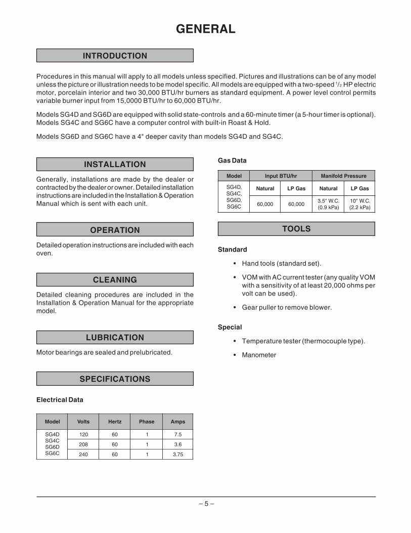
Electrical Data .................................................................................................................................... 5Gas Data ............................................................................................................................................. 5
Tools ......................................................................................................................................................... 5Standard ............................................................................................................................................. 5Special ................................................................................................................................................ 5
REMOVAL AND REPLACEMENT OF PARTS ..................................................................................................... 6
Component Location ................................................................................................................................. 6Covers and Panels ................................................................................................................................... 7
Top Front Cover .................................................................................................................................. 7Bottom Front Cover ............................................................................................................................ 7Control Panel ...................................................................................................................................... 7Right Side Panel ................................................................................................................................. 7
Control Panel Components ....................................................................................................................... 8Procedure ........................................................................................................................................... 8
Component Panel Components ................................................................................................................ 9Procedure ........................................................................................................................................... 9
Temperature Probe ..................................................................................................................................10Gas Burners .............................................................................................................................................11Gas Orifice ...............................................................................................................................................12Gas Solenoid Valve .................................................................................................................................12Ignition Control Module ............................................................................................................................13Spark Igniter and Flame Sense ...............................................................................................................13Blower and Motor .....................................................................................................................................14Oven Doors and Bearings .......................................................................................................................15Roller Latch Assembly .............................................................................................................................16Door Catch Assembly .............................................................................................................................. 16Door Window ............................................................................................................................................16Door Switch .............................................................................................................................................. 17High Limit Thermostat .............................................................................................................................18Interior Lights ........................................................................................................................................... 18
Lamp Assembly ................................................................................................................................. 18Cooling Fan .............................................................................................................................................. 19
Fan Installation Tips ..........................................................................................................................19
SERVICE PROCEDURES AND ADJUSTMENTS ...............................................................................................20
Solid State Temperature Controller Test (SG4D/SG6D) ........................................................................20Test Steps .........................................................................................................................................20
Solid State Temperature Controller Calibration (SG4D/SG6D)..............................................................21Calibration Steps ...............................................................................................................................21Calibration Tips .................................................................................................................................21
Temperature Probe Test (SG4D/SG6D) .................................................................................................22Test Steps .........................................................................................................................................22
– 4 –
TABLE OF CONTENTS (Cont.)
Computer Controller (SG4C/SG6C) .........................................................................................................23Operation ...........................................................................................................................................23Setup Mode .......................................................................................................................................23Probe Test .........................................................................................................................................23Solid State Relay Test ......................................................................................................................24
Computer Controller Calibration (SG4C/SG6C) .......................................................................................24Calibration Steps ...............................................................................................................................24
Gas Pressure Adjustment .......................................................................................................................25Verification of Spark at Igniter ................................................................................................................26Door Switch Adjustment ..........................................................................................................................26Flame Current Measurements .................................................................................................................27Blower Adjustment ...................................................................................................................................27Door Adjustment ......................................................................................................................................28Door Strike Adjustment ............................................................................................................................ 28Door Catch Roller Adjustment .................................................................................................................29
ELECTRICAL OPERATION .................................................................................................................................30
Component Description ...........................................................................................................................30Plug, Socket and Components (SG4D/SG6D) ........................................................................................31Plug, Socket and Components (SG4C/SG6C) ........................................................................................32Sequence of Operations ..........................................................................................................................33
SG4D/SG6D with Solid State Temperature Controller .....................................................................33Cook Cycle ........................................................................................................................................33Timer Cycle .......................................................................................................................................34Cool Down Cycle (Solid State Temperature Controller) ...................................................................34SG4C/SG6C with Computer Controller .............................................................................................35
Normal Cook Cycle .....................................................................................................................35Temperature and Time Cycle (Normal Cooking) ...............................................................................37Function Switch (SG4C/SG6C) .........................................................................................................37Roast and Hold Cycle........................................................................................................................37
Wiring Diagrams .......................................................................................................................................38Schematics ..............................................................................................................................................40
TROUBLESHOOTING ..........................................................................................................................................42Error Codes ..............................................................................................................................................44
– 5 –
INSTALLATION
Generally, installations are made by the dealer orcontracted by the dealer or owner. Detailed installationinstructions are included in the Installation & OperationManual which is sent with each unit.
OPERATION
Detailed operation instructions are included with eachoven.
CLEANING
Detailed cleaning procedures are included in theInstallation & Operation Manual for the appropriatemodel.
LUBRICATION
Motor bearings are sealed and prelubricated.
SPECIFICATIONS
Electrical Data
INTRODUCTION
GENERAL
Gas Data
TOOLS
Standard
• Hand tools (standard set).
• VOM with AC current tester (any quality VOMwith a sensitivity of at least 20,000 ohms pervolt can be used).
• Gear puller to remove blower.
Special
• Temperature tester (thermocouple type).
• Manometer
Procedures in this manual will apply to all models unless specified. Pictures and illustrations can be of any modelunless the picture or illustration needs to be model specific. All models are equipped with a two-speed 1/2 HP electricmotor, porcelain interior and two 30,000 BTU/hr burners as standard equipment. A power level control permitsvariable burner input from 15,0000 BTU/hr to 60,000 BTU/hr.
Models SG4D and SG6D are equipped with solid state-controls and a 60-minute timer (a 5-hour timer is optional).Models SG4C and SG6C have a computer control with built-in Roast & Hold.
Models SG6D and SG6C have a 4" deeper cavity than models SG4D and SG4C.
ledoM stloV ztreH esahP spmA
D4GSC4GSD6GSC6GS
021 06 1 5.7
802 06 1 6.3
042 06 1 57.3
ledoM tupnI UTB rh/ erusserPdlofinaM
,D4GS,C4GS,D6GS
C6GS
larutaN saGPL larutaN saGPL
000,06 000,06.C.W"5.3)aPk9.0(
.C.W"01)aPk2.2(

– 6 –
REMOVAL AND REPLACEMENT OF PARTS
COMPONENT LOCATION
DOORSWITCH
IGNITER &FLAME SENSE
GAS BURNERSCOMPONENT
PANEL
COOLINGFAN
OVEN LIGHTS
CONTROLPANEL
TOP VIEW
BLOWER MOTOR
TEMPERATURE PROBE
HIGH LIMIT
GAS VALVE
PL-56044
– 7 –
COVERS AND PANELS
Disconnect theelectrical power to the machine andfollow lockout / tagout procedures.
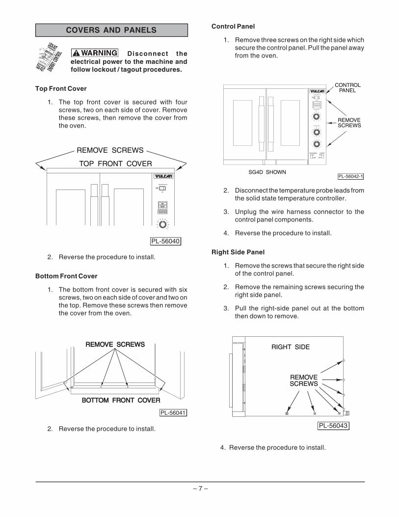
Top Front Cover
1. The top front cover is secured with fourscrews, two on each side of cover. Removethese screws, then remove the cover fromthe oven.
2. Reverse the procedure to install.
Bottom Front Cover
1. The bottom front cover is secured with sixscrews, two on each side of cover and two onthe top. Remove these screws then removethe cover from the oven.
2. Reverse the procedure to install.
Control Panel
1. Remove three screws on the right side whichsecure the control panel. Pull the panel awayfrom the oven.
2. Disconnect the temperature probe leads fromthe solid state temperature controller.
3. Unplug the wire harness connector to thecontrol panel components.
4. Reverse the procedure to install.
Right Side Panel
1. Remove the screws that secure the right sideof the control panel.
2. Remove the remaining screws securing theright side panel.
3. Pull the right-side panel out at the bottomthen down to remove.
4. Reverse the procedure to install.
RIGHT SIDERIGHT SIDE
REMOVEREMOVESCREWSSCREWS
PL-56043
TOP FRONT COVER
REMOVE SCREWS
PL-56040
OFF
OVENCOOL
MASTER SWITCH
ON
HEAT
IGNITION
REMOVESCREWS
CONTROLPANEL
ONHI
OFFLOW
LIGHTSFAN SPEED
SG4D SHOWN
THERMOSTAT
POWER LEVEL
OFF
OVENCOOL
MASTER SWITC H
PL-56042-1
BOTTOM FRONT COVERBOTTOM FRONT COVER
REMOVE SCREWSREMOVE SCREWS
PL-56041
– 8 –
CONTROL PANEL COMPONENTS
Procedure
Disconnect the electrical power to the machine and follow lockout / tagoutprocedures.
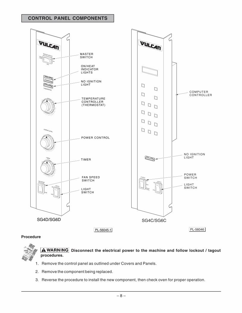
1. Remove the control panel as outlined under Covers and Panels.
2. Remove the component being replaced.
3. Reverse the procedure to install the new component, then check oven for proper operation.
MASTERSWITCH
SG4D/SG6D
PL-56045-1
THERMOSTAT
55
5045
4035
30
0
25
TIMER
55
5045
4035
30
0
25
HI
FAN SPEED
LOW
ONLIGHTS
OFF
OFF
OVENCOOL
ON
MASTER SWITCH
POWER LEVEL
ON/HEAT INDICATORLIGHTS
NO IGNITIONLIGHT
TEMPERATURECONTROLLER(THERMOSTAT)
POWER CONTROL
TIMER
LIGHTSWITCH
FAN SPEED SWITCH
SG4C/SG6C
ON
OFF
POWER
OVENCOOL
ONLIGHTS
OFF
L IGHTSWITCH
POWERSWITCH
NO IGNITIONLIGHT
COMPUTERCONTROLLER
PL-56046

– 9 –
COMPONENT PANEL COMPONENTS
Procedure
Disconnect the electrical power to the machine and follow lockout / tagoutprocedures.
1. Remove the right side panel as outlined under Covers and Panels.
2. Disconnect the wire leads to the component being replaced.
3. Remove the component.
4. Reverse the procedure to install the new component and check oven for proper operation.
PL-56047
IGNITION MODULE
IGNITION MODULEBOARD
HEATINGRELAY
PORCELAINBLOCKASSEMBLY
PORCELAINBLOCKASSEMBLY
SG4D/SG6D
TRANSFORMER
MOTORCONTROLRELAYS
IGNITION MODULEBOARD
IGNITION MODULE
PORCELAINBLOCKASSEMBLY
HEATING RELAY
PORCELAINBLOCKASSEMBLY
SG4C/SG6C
TRANSFORMER
PL-56048
– 10 –
TEMPERATURE PROBE
Disconnect theelectrical power to the machine andfollow lockout / tagout procedures.
1. Remove the right-side panel as outlined underCovers and Panels.
2. Disconnect probe leads from the solid statetemperature controller on the SG4D/SG6D orthe computer controller on the SG4C/SG6C.
3. Remove the racks and right rack support.
4. Remove the upper and lower door seals.
5. Loosen the three screws securing the rightside air scoop to the rear heat exchanger.Rotate the air scoop off of the heat exchangertube into the oven cavity.
6. Remove the screws that secure the perforatedside panel and lift out.
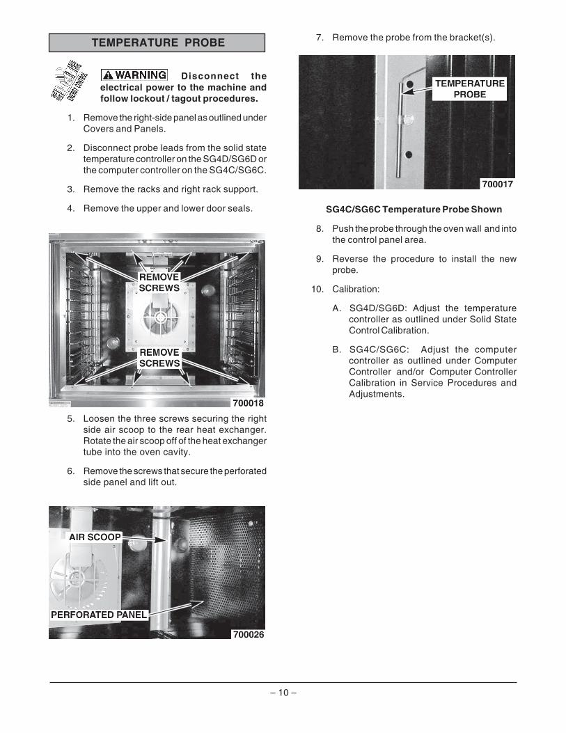
7. Remove the probe from the bracket(s).
SG4C/SG6C Temperature Probe Shown
8. Push the probe through the oven wall and intothe control panel area.
9. Reverse the procedure to install the newprobe.
10. Calibration:
A. SG4D/SG6D: Adjust the temperaturecontroller as outlined under Solid StateControl Calibration.
B. SG4C/SG6C: Adjust the computercontroller as outlined under ComputerController and/or Computer ControllerCalibration in Service Procedures andAdjustments.
– 11 –
GAS BURNERS
Disconnect theelectrical power to the machine andfollow lockout / tagout procedures.
Shut off the gas before servicingthe oven.
1. Remove the lower front cover as outlinedunder Covers and Panels.
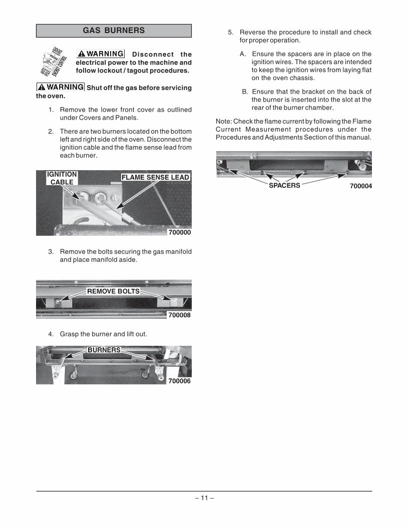
2. There are two burners located on the bottomleft and right side of the oven. Disconnect theignition cable and the flame sense lead fromeach burner.
3. Remove the bolts securing the gas manifoldand place manifold aside.
4. Grasp the burner and lift out.
5. Reverse the procedure to install and checkfor proper operation.
A. Ensure the spacers are in place on theignition wires. The spacers are intendedto keep the ignition wires from laying flaton the oven chassis.
B. Ensure that the bracket on the back ofthe burner is inserted into the slot at therear of the burner chamber.
Note: Check the flame current by following the FlameCurrent Measurement procedures under theProcedures and Adjustments Section of this manual.
– 12 –
GAS ORIFICE
Disconnect theelectrical power to the machine andfollow lockout / tagout procedures.
Shut off the gas before servicingthe oven.
1. Remove the lower front cover as outlinedunder Covers and Panels.
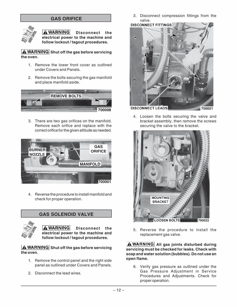
2. Remove the bolts securing the gas manifoldand place manifold aside.
3. There are two gas orifices on the manifold.Remove each orifice and replace with thecorrect orifice for the given altitude as needed.
4. Reverse the procedure to install manifold andcheck for proper operation.
GAS SOLENOID VALVE
Disconnect theelectrical power to the machine andfollow lockout / tagout procedures.
Shut off the gas before servicingthe oven.
1. Remove the control panel and the right sidepanel as outlined under Covers and Panels.
2. Disconnect the lead wires.
3. Disconnect compression fittings from thevalve.
4. Loosen the bolts securing the valve andbracket assembly, then remove the screwssecuring the valve to the bracket.
5. Reverse the procedure to install thereplacement gas valve.
All gas joints disturbed duringservicing must be checked for leaks. Check withsoap and water solution (bubbles). Do not use anopen flame.
6. Verify gas pressure as outlined under theGas Pressure Adjustment in ServiceProcedures and Adjustments. Check forproper operation.
– 13 –
IGNITION CONTROL MODULE
Disconnect theelectrical power to the machine andfollow lockout / tagout procedures.
1. Remove the right side cover as outlinedunder Covers and Panels.
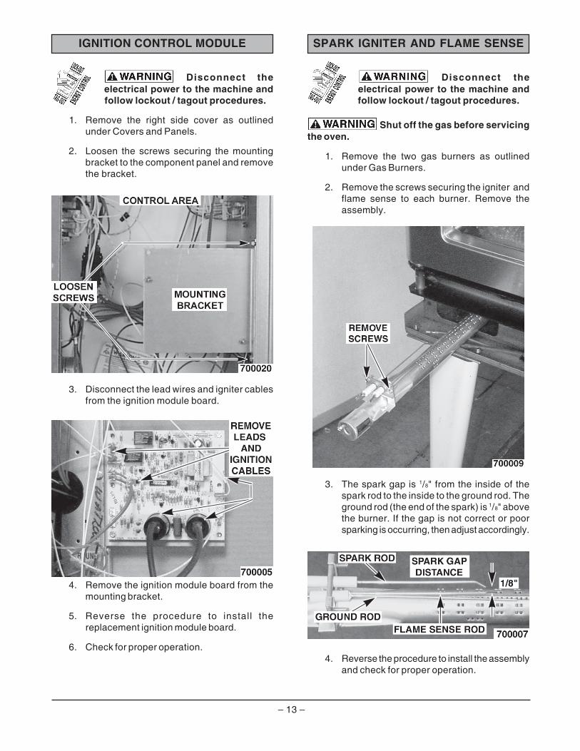
2. Loosen the screws securing the mountingbracket to the component panel and removethe bracket.
3. Disconnect the lead wires and igniter cablesfrom the ignition module board.
4. Remove the ignition module board from themounting bracket.
5. Reverse the procedure to install thereplacement ignition module board.
6. Check for proper operation.
SPARK IGNITER AND FLAME SENSE
Disconnect theelectrical power to the machine andfollow lockout / tagout procedures.
Shut off the gas before servicingthe oven.
1. Remove the two gas burners as outlinedunder Gas Burners.
2. Remove the screws securing the igniter andflame sense to each burner. Remove theassembly.
3. The spark gap is 1/8" from the inside of thespark rod to the inside to the ground rod. Theground rod (the end of the spark) is 1/8" abovethe burner. If the gap is not correct or poorsparking is occurring, then adjust accordingly.
4. Reverse the procedure to install the assemblyand check for proper operation.

– 14 –
BLOWER AND MOTOR
Disconnect theelectrical power to the machine andfollow lockout / tagout procedures.
1. Remove racks.
2. Remove the screws securing the snorkel andremove the snorkel.
3. Remove screws securing baffle panel andremove the panel.
4. If replacing:
A. Blower Only - Loosen set screws onblower hub and using a bearing puller,remove blower from motor shaft.
1) Reverse procedure to install andadjust blower position as outlinedunder the Blower Adjustment inService Procedures and Adjustmentssection.
B. Motor - Perform step 4A and continueprocedure.
5. Remove the screws that secure the motormounting plate to the rear wall.
6. Place a piece of cardboard on the bottom ofthe oven cavity to protect its surface fromany damage during motor assembly removal.
7. Pull the motor assembly into the oven cavityand place it on the cardboard.
8. Remove the junction box cover from themotor, disconnect lead wires and remove theconduit.
9. Remove motor mounting bolts and flatwashers, then lift the motor from the mountingplate.
10. Position the replacement motor on the motormounting plate and install mounting bolts andwashers. Hand tighten mounting bolts only.
11. Reconnect to lead wires at the motor, andreplace conduit and junction box cover.

– 15 –
12. Slide blower onto motor shaft until hub isflush with end of shaft, then tighten setscrews.
13. Adjust motor position until blower is parallelto motor mounting plate as outlined in BlowerAdjustment under Service Procedures andAdjustments.
14. Position motor mounting plate on the rearwall and secure with nuts and washers.
15. Replace the baffle panel and snorkel.
16. Replace the air baffle on the rear wall at thelower right hand corner.
17. Remove cardboard from the bottom of theoven cavity.
18. Install racks.
19. Check oven for proper operation.
OVEN DOORS AND BEARINGS
Disconnect theelectrical power to the machine andfollow lockout / tagout procedures.
1. Remove the top front cover and bottom frontcover as outlined under Covers and Panels.
2. Remove the door switch lever.
3. Remove the lower door seal strip to exposethe mounting screws of the door assembly.
4. Remove the two lower sill bolts by the lowerdoor shaft and the four countersunk screwsfrom the lower sill.
A. The door assembly is heavy and will dropdown once the last screw is removed. Ifremoving the door assembly withoutassistance, the ignition cable, flamesense lead and gas manifold should alsobe removed to avoid damage to thesecomponents.
5. Tilt the top of the door slightly forward and liftthe door up until the bottom of the door shaftclears the opening in the sill.
6. Lay the door flat to prevent damage.
PL-56051 MOTOR ROTATES CLOCKWISE
FRONT VIEW OF MOTORFROM INSIDE OVEN CAVITY

– 16 –
7. The top and bottom bearings are nowaccessible for inspection and/or replacementif needed.
A. If bearings are OK, proceed to step 8.
B. If replacing the top bearing, remove thetop bearing retainer and top bearing.
C. If replacing the bottom bearing, remove itfrom the door shaft or the lower sillopening.
8. Reverse procedure to install door assemblyand check for proper operation as outlinedunder the Door Adjustment and Door SwitchAdjustment section in Procedures andAdjustments.
ROLLER LATCH ASSEMBLY(INDEPENDENT DOORS)
NOTE: For units with serial number starting with 48made after 8/12/07 and serial number starting with 54made after 8/26/07.
Disconnect theelectrical power to the machine andfollow lockout / tagout procedures.
1. Remove the screws that attach roller latchassembly to door.
2. Reverse procedure to install.
DOOR WINDOW
Disconnect theelectrical power to the machine andfollow lockout / tagout procedures.
1. Remove the screws at the top and bottom ofthe door.
GLASS
REMOVESCREWS
OVEN CAVITY
PL-56052
DOOR CATCH ROLLER ASSEMBLY(INDEPENDENT DOORS)
NOTE: For units with serial number starting with 48made before 8/13/07 and serial number starting with54 made before 8/27/07.
Disconnect theelectrical power to the machine andfollow lockout / tagout procedures.
1. Remove the top front cover as outlined underCOVERS AND PANELS.
2. Remove the nuts and bolts that secure thedoor catch assembly.
3. Reverse the procedure to install.
4. Adjust the roller catch as outlined under theDoor Catch Adjustment in Service Proceduresand Adjustments.

– 17 –
DOOR SWITCH
Disconnect theelectrical power to the machine andfollow lockout / tagout procedures.
1. Remove the top front cover as outlined underCovers and Panel.
2. Disconnect the lead wires to the door switch.
GLASS
GLASS
REMOVE SCREWS
INNER DOOR PANEL ASSEMBLY
PL-56053
2. Remove the door handle, then remove theouter door panel.
3. Lift out the inner door panel window assembly.
4. Remove the door seal from the inside of theleft door only.
5. Remove the screws securing the windowtabs to the door bracket and lift the windowassembly out from the door frame.
6. Reverse procedure to install the replacementwindow.
3. Remove the switch.
4. Reverse procedure to install the replacementswitch and check for proper adjustment asoutlined in Door Switch under ServiceProcedures and Adjustments.

– 18 –
Lamp Assembly
1. Remove the lens and bulb.
2. Remove the springs from the retaining tabs(two places) on the socket.
3. Depress the retaining tabs and pull the socketout from the oven, far enough to disconnectthe lead wires.
4. Remove the socket from the oven.
RETAINING TABS
SPRING
CROSS SECTIONAL VIEW PL-56055
3. Disconnect the lead wires from the high limitthermostat. Remove the high limit thermostatfrom the cover mounting plate.
4. Remove the old RTV silicone from the coverand mating surfaces inside the oven cavity,and apply new RTV silicone before installing.
5. Reverse procedure to install.
INTERIOR LIGHTS
Disconnect theelectrical power to the machine andfollow lockout / tagout procedures.
1. Remove the racks from the oven.
2. Unscrew the glass lens for the light beingreplaced, then unscrew the bulb.
3. Replace bulb, then reverse the procedure toinstall.
LENSLENS
OVEN CAVITY
PL-56054
HIGH LIMIT THERMOSTAT
Disconnect theelectrical power to the machine andfollow lockout / tagout procedures.
1. Remove the top four racks from the oven.
2. Remove the high limit thermostat cover/mounting plate. It is located at the top of theoven cavity.
– 19 –
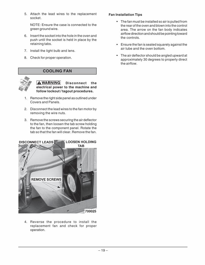
COOLING FAN
Disconnect theelectrical power to the machine andfollow lockout / tagout procedures.
1. Remove the right side panel as outlined underCovers and Panels.
2. Disconnect the lead wires to the fan motor byremoving the wire nuts.
3. Remove the screws securing the air deflectorto the fan, then loosen the tab screw holdingthe fan to the component panel. Rotate thetab so that the fan will clear. Remove the fan.
4. Reverse the procedure to install thereplacement fan and check for properoperation.
5. Attach the lead wires to the replacementsocket.
NOTE: Ensure the case is connected to thegreen ground wire.
6. Insert the socket into the hole in the oven andpush until the socket is held in place by theretaining tabs.
7. Install the light bulb and lens.
8. Check for proper operation.
Fan Installation Tips
• The fan must be installed so air is pulled fromthe rear of the oven and blown into the controlarea. The arrow on the fan body indicatesairflow direction and should be pointing towardthe controls.
• Ensure the fan is seated squarely against theair tube and the oven bottom.
• The air deflector should be angled upward atapproximately 30 degrees to properly directthe airflow.

– 20 –
SOLID STATE TEMPERATURECONTROLLER TEST
(SG4D/SG6D)
Test Steps
1. Remove the right side panel as outlinedunder Cover and Panels in Removal andReplacement of Parts.
2. Place a thermocouple in the geometric centerof the oven cavity. Oven temperature mustbe below 450°F.
3. Set the temperature control to the maximumsetting.
4. Set the power control to 100%.
5. Check machine data plate for correct voltageto oven. Refer to diagram below for properterminal locations and voltages beforechecking temperature controller. Use thecorrect terminals for the correspondingvoltage.
6. Turn the ON-OFF-OVEN-COOL switch toON.
7. Check for voltage across terminals J2 and J4(120 Volt) or J2 and J9 (208/240 Volt) forpower to the control.
a. If correct, proceed to step 8.
b. If incorrect, the problem is not in thetemperature control (seeTroubleshooting).
SERVICE PROCEDURES AND ADJUSTMENTS
Certain procedures in this section require electrical test or measurements while power isapplied to the machine. Exercise extreme caution at all times. If test points are not easily accessible, discernpower, attach test equipment and reapply power to test.
8. Check for voltage to the switching output.
a. For 120 VAC controls, check acrossterminals J3 and J4 for input voltage andbetween J4 and J5 for output voltagefrom the internal switching device.
b. For 208/240 VAC controls, check acrossterminals J3 and J9 for input voltage andbetween J9 and J5 for output voltagefrom the internal switching device.
1) If input voltage is correct, proceed tostep 9. If input voltage is not present,the problem is not in the controller(See Troubleshooting).
2) If output voltage is correct, proceedto step 9. If output voltage is notcorrect, check temperature probe,as outlined under Temperature ProbeTest (SG4D/SG6D).
c. If the probe connected to J6 and J7 iseither shorted or opened, the red LEDlocated just above J6 (to the left of J6when mounted) will flash. With the probeconnected and the LED not flashing,slowly turn the Temperature set knobuntil the pointer passes through the midpoint of rotation. At the mid point ofrotation, the red LED will come on. If thecontrol is set and left at the mid point, theLED will stay on. With the LED on at midpoint, you have tested the entire frontend of the control circuit as well as theprobe and verified that the control isfunctioning normally.
9. Set temperature control to minimum setting.Oven temperature must be above 300°F.
10. Check for zero volts (0.00 Volts) acrossterminals J4 and J5 (120 Volt) or J9 and J5(208/240 Volt) for no output from the internalswitching device.
a. If correct, temperature control isfunctioning properly.
– 21 –
SOLID STATE TEMPERATURECONTROL CALIBRATION
(SG4D/SG6D)
Before attempting any calibration, see Section 8C ofSOLID STATE TEMPERATURE CONTROLLERTEST (SG4D/SG6D) on previous page.
Calibration Steps
1. Place a thermocouple in the geometric centerof the oven cavity.
2. Set the ON/OFF/OVEN COOL switch to ON.
3. Set the temperature controller dial to 350°F.Set the power control to 100% (10).
4. Allow the oven temperature to stabilize(minimum three heating cycles).
5. Record the temperature at which the Heatlamp comes ON (heating starts) and goesOFF (heating stops). This is the controldifferential. Heat lamp OFF temp - Heat lampON temp = Control Differential.
6. The nominal control differential should beless than 20°F.
A. If the control differential is less than20°F, the temperature control circuit isfunctioning properly. Proceed to step 7.
B. If the control differential is more than20°F, check the temperature probe asoutlined under Temperature Probe Test(SG4D/SG6D).
C. If the control differential is more than20°F and the probe passes its' testparameters, then temperature controlleris malfunct ioning. Instal l a newtemperature controller and run calibrationsteps again.
7. Calculate the average oven temperature byadding the actual minimum temperature tothe actual maximum temperature and dividingby 2.
EXAMPLE:Oven set to 350°F.Actual minimum oven temperature = 335°FControl cuts on at 334°FActual maximum oven temperature = 347°FControl cuts off at 340°F335 + 347 = 682682/ 2 = 341 (the control is 9°F out of calibration)340 - 334 = 6°F Control Differential347 - 335 = 12°F Oven Temperature Differential
A. If the average oven temperature is within+/- 5°F from the dial setting, no calibrationis necessary.
B. If the average oven temperature is notwithin +/- 5°F, cal ibrat ion isrecommended.
8. Loosen the set screw on the temperaturecontroller and carefully remove the knob fromthe shaft, without rotating the shaft. This willexpose the calibration adjustment controlaccess hole in the front panel.
9. Monitor the internal oven temperature anddetermine at what temperature the controlshould cut on to give you the required minimumtemperature (Example: 350-341=9;334+9=341. 341°F is the temperature at whichyou would wish the controller to cut on).
10. After allowing the oven to operate throughseveral cycles (minimum 3 cycles), monitorthe temperature as it falls to the desired "cutson" point. Using a small screw driver, adjustthe calibration adjustment until the controllercuts on at the desired "cuts on" temperature.
11. The calibration control is adjusted clockwisein order to increase the set temperature andcounter clockwise to decrease the settemperature.
12. The controller has only +/- 25°F of adjustment.1/4 turn of the calibration adjustment representsapproximately 20°F shift in calibration.
b. If incorrect, check temperature probe asoutlined under Temperature Probe Test(SG4D/SG6D).
1) If temperature probe is functioningproperly and the temperaturecontroller failed the test in 8c above,replace the temperature control andcheck for calibration as outlined underSolid State Temperature ControllerCalibration (SG4D/SG6D).

– 22 –
TEMPERATURE PROBE TEST (SG4D/SG6D)
Disconnect the electrical power to the machine and follow lockout / tagoutprocedures.
The temperature probe used in conjunction with the Solid State Temperature controller is an RTD (resistancetemperature detector) of the Thermistor type. As temperature increases the resistance value decreases.
Test Steps
1. Remove the right side panel as outlined under Cover and Panels in Removal and Replacement of Parts.
2. Place a shielded thermocouple in the geometric center of the oven cavity and determine the temperaturein the oven cavity.
3. Remove the probe lead wires from the solid state temperature controller.
4. Test the probe with an ohmmeter.
A. If the measured resistance values are inside the given tolerance, then the probe is functioning properly.
B. If the measured resistance values are outside the given tolerance, then replace the probe and makesure wires are secured to the terminals of the temperature controller. Recheck the temperature bypreforming step 2.
1) Check the oven for proper operation.
5. Reverse Procedure to install.
)F°(PMET *SMHO
77 000,09
042 770,4
062 610,3
082 662,2
003 627,1
023 233,1
043 140,1
063 228
083 656
004 925
524 424
054 433
574 662
%01±smhoniecnatsiseR)*(

– 23 –
COMPUTER CONTROLLER(SG4C/SG6C)
Operation
Refer to the Installation & Operation Manual forspecific operating instructions.
Setup Mode
Use the setup mode to verify that the control isconfigured to the factory settings which result in theproper operation of the oven. If the CAL1 parameteris other than zero, see Computer Control Calibration(SG4C/SG6C).
CAUTION: Changing the C_F, InP1, rL1 and rH1parameters will default all menus.
1. Use this key sequence to access the setupmode: UP arrow, Rack 1, Temperature,Temperature, DOWN arrow, Rack 1.
2. Once in the setup mode the display willalternate between the parameter andprogrammed data.
A. To change data to the factory setting,use the arrow keys.
B. To select the next parameter, press theRack 1 key.
C. After the last parameter and data areviewed, press the Rack 1 key to exit thesetup mode and return to operationsmode. The current set point temperaturewill be displayed.
D. If there are no key activations after 1minute, the control will return to operationmode.
3. Listed are the parameters and data in thesetup mode.
Probe Test
If the oven is not heating or displaying the propertemperature, the temperature probe may bemalfunctioning. Determine if the probe is good orcausing the operational problem.
1. Temporarily disconnect the existing lead wiresfrom the computer control and connect themto a good J-type thermocouple.
2. Turn the power switch to ON and set thetemperature controller to 350°F.
A. If the oven reaches the set temperatureand cycles with the temporarythermocouple, then the existing probe ismalfunctioning.
3. Replace the temperature probe with the correctpart and check for proper operation.
11PL-56075
UNEMYALPSIDNOGNITANRETLA
RETEMARAP ATAD
tiehnerhaF_suisleC F_C F
dnaBdrauG bg 0004
erutarepmeTnoiatsnepmoC
Pnct FFO
1epyTtupnI 1PnI J
1woLegnaR 1Lr 57
1hgiHegnaR 1Hr 005
siseretsyH 1SYH 3
tesffOnoitarbilaC 1LAC 0
edomputestixEotnruterdna
.edomnoitarepo
sierutarepmettniopteS,taehrofgnillacfirodeyalpsid
.deyalpsidera)----(sehsad

– 24 –
Solid State Relay Test
1. Remove the right side panels as outlinedunder Covers and Panels in Removal andReplacement of Parts.
2. Turn the power switch to the ON position.
3. Check for +5 VDC on input side of SSR-1 inthe normal heating mode (terminals 3 & 4)and SSR-2 in the roast and hold mode.
A. If +5 VDC is present, continue to step 4.
B. If no voltage is present, computer controlis not functioning properly.
4. Check for 120 VAC at load side of SSR(terminals 1 & 2).
A. If no voltage is present, solid state relayis not functioning properly.
1) Replace the SSR and check for properoperation.
B. If 120 VAC is present, component isfunctioning properly.
5. Reassemble oven and check for properoperation.
COMPUTER CONTROL CALIBRATION(SG4C/SG6C)
Calibration Steps
1. Place a thermocouple in the geometric centerof the oven cavity.
2. Set the ON-OFF-COOL DOWN switch to ON.
A. If the set point temperature is 350°F,proceed to step 4.
B. If the set point temperature is other than350°F, proceed to step 3 to change thetemperature.
3. Press the set key then temperature key toenter the temperature set mode.
A. The display will alternate between theterm StPt (set point) and the currentoven temperature setting.
B. Press the UP or DOWN arrows to makethe proper selection.
C. Press the set key again to save the change,then exit the temperature set mode.
4. Allow the oven temperature to stabilize(normally three cycles).
5. Compare the controls set point temperatureto the thermocouple meter reading when theheat light goes out.
A. A temperature variance more than 5°Findicates an adjustment is needed.
1) To make the adjustment, proceed tostep 6.
2) If temperature variances is less than5°F, then the computer control isfunctioning properly.
6. Enter the setup mode as outline in SetupMode under Computer Control (SG4C/SG6C).
A. Advance through the menu until CAL1(calibration offset) appears.
1) If the thermocouple reading is higherthan set point temperature, press thedown arrow key and enter a negativeoffset value that is equal to thenumber of degrees above the 5°Ftolerance.
2) If the thermocouple reading is lowerthan set point temperature, press theUP arrow and enter a positive offsetvalue that is equal to the number ofdegrees below the 5°F tolerance.
3) Exit the setup mode.
7. Allow the oven to cycle at least two timesbetween adjustments.
A. If the temperature variance still differsmore than 5°F from the set point, verifythe correct calibration offset value wasentered and retained.
1) Adjust the calibration offset value asoutlined in step 6, until the cyclingtemperature is within tolerance.
B. If the above adjustment cannot beobtained, replace the computer controland check for proper operation.

– 25 –
GAS PRESSURE ADJUSTMENT
Disconnect theelectrical power to the machine andfollow lockout / tagout procedures.
Accurate gas pressure adjustments can only bemade with the gas on and the burner lit. If theincoming line pressure to the valve is less than theminimum stated, then the manifold pressure cannotbe set correctly.
1. Turn gas supply off at manual shutoff valve.
2. Remove the right side panel as outlinedunder Covers and Panels in Removal andReplacement of Parts.
3. Remove the plug from the manifold pressureport.
4. Install hose barb adapter and attachmanometer tube.
5. Remove adjustment screw cap from the gasvalve and turn gas supply to the oven backon.
The following steps require powerto be applied to the unit during test. Use extremecaution at all times.
6. Plug the unit in and turn the power switch ON.
7. Set the temperature controller to its highestsetting and allow burner to ignite. The burnermust be lit during test and adjustment.
8. Turn the set screw to obtain the proper gaspressure (clockwise = pressure increase;counterclockwise = pressure decrease).
SAGEPYT
).C.WNI(SGNIDAERERUSSERP
DLOFINAMENIL
DEDNEMMOCER NIM XAM
larutaN 5.3 0.7 0.541
enaporP 01 0.11 0.11
– 26 –
VERIFICATION OF SPARK AT IGNITOR
Disconnect theelectrical power to the machine andfollow lockout / tagout procedures.
Shut off the gas before servicingthe oven.
1. Remove the bottom front cover as outlinedunder Covers and Panels in Removal andReplacement of Parts.
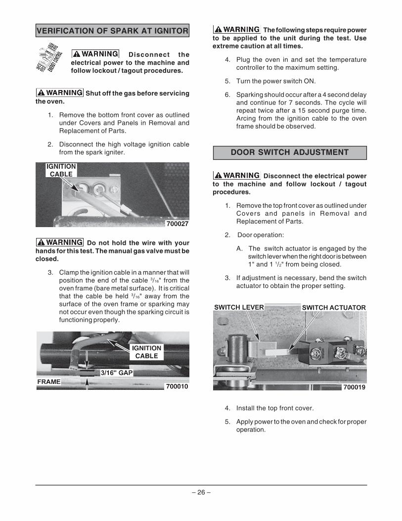
2. Disconnect the high voltage ignition cablefrom the spark igniter.
Do not hold the wire with yourhands for this test. The manual gas valve must beclosed.
3. Clamp the ignition cable in a manner that willposition the end of the cable 3/16" from theoven frame (bare metal surface). It is criticalthat the cable be held 3/16" away from thesurface of the oven frame or sparking maynot occur even though the sparking circuit isfunctioning properly.
The following steps require powerto be applied to the unit during the test. Useextreme caution at all times.
4. Plug the oven in and set the temperaturecontroller to the maximum setting.
5. Turn the power switch ON.
6. Sparking should occur after a 4 second delayand continue for 7 seconds. The cycle willrepeat twice after a 15 second purge time.Arcing from the ignition cable to the ovenframe should be observed.
DOOR SWITCH ADJUSTMENT
Disconnect the electrical powerto the machine and follow lockout / tagoutprocedures.
1. Remove the top front cover as outlined underCovers and panels in Removal andReplacement of Parts.
2. Door operation:
A. The switch actuator is engaged by theswitch lever when the right door is between1" and 1 1/2" from being closed.
3. If adjustment is necessary, bend the switchactuator to obtain the proper setting.
4. Install the top front cover.
5. Apply power to the oven and check for properoperation.
– 27 –
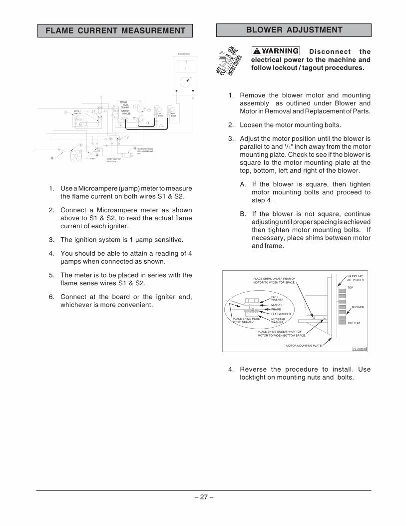
Disconnect theelectrical power to the machine andfollow lockout / tagout procedures.
1. Remove the blower motor and mountingassembly as outlined under Blower andMotor in Removal and Replacement of Parts.
2. Loosen the motor mounting bolts.
3. Adjust the motor position until the blower isparallel to and 1/4" inch away from the motormounting plate. Check to see if the blower issquare to the motor mounting plate at thetop, bottom, left and right of the blower.
A. If the blower is square, then tightenmotor mounting bolts and proceed tostep 4.
B. If the blower is not square, continueadjusting until proper spacing is achievedthen tighten motor mounting bolts. Ifnecessary, place shims between motorand frame.
4. Reverse the procedure to install. Uselocktight on mounting nuts and bolts.
BLOWER ADJUSTMENT
MOTOR MOUNTING PLATE
PLACE SHIMS UNDER FRONT OFMOTOR TO WIDEN BOTTOM SPACE.
PLACE SHIMS UNDER REAR OFMOTOR TO WIDEN TOP SPACE.
BOTTOM
TOP
PLACE SHIMS HEREWHEN NEEDED.
FLATWASHER
MOTOR
FRAME
FLAT WASHER
NUT/STARWASHER
1/4 INCH ATALL PLACES
BLOWER
PL-56058
1. Use a Microampere (µamp) meter to measurethe flame current on both wires S1 & S2.
2. Connect a Microampere meter as shownabove to S1 & S2, to read the actual flamecurrent of each igniter.
3. The ignition system is 1 µamp sensitive.
4. You should be able to attain a reading of 4µamps when connected as shown.
5. The meter is to be placed in series with theflame sense wires S1 & S2.
6. Connect at the board or the igniter end,whichever is more convenient.
FLAME CURRENT MEASUREMENT
S1
S2
56
59
48
57
LEFT RIGHT
Y
BURNER BURNER
52
57
S1
8
XD
S2
56
C-21 2 3
U345519-4
424471-G1
2
2
1
TH3
55
LEDDUAL IND
ICA
TOR
DIA
GN
OSTIC
MODULEIGNITIONCHANNEL
FC1-
FC1+
OUTSPARK
FC2-
FC2+
S2
S1
V2
W
NC
V1
OUTSPARK
RED
GND
24V
FENWAL
T
L
2
L2L1
1
W
PLUG.WHITE
BLACK
GREEN
48
6
V
GND.
AB
46
5
120 VOLT UNITS PROVIDEDWITH 3 PRONG GROUNDED
AB 417856-1 CONNECT 200-240 VOLTSUPPLY TO L1 & L2
10
4
MICROAMP METER
– 28 –
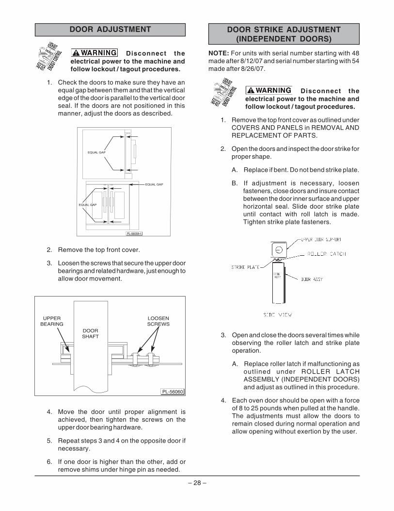
Disconnect theelectrical power to the machine andfollow lockout / tagout procedures.
1. Check the doors to make sure they have anequal gap between them and that the verticaledge of the door is parallel to the vertical doorseal. If the doors are not positioned in thismanner, adjust the doors as described.
EQUAL GAP
EQUAL GAP
PL-56059-1
EQUAL GAP
2. Remove the top front cover.
3. Loosen the screws that secure the upper doorbearings and related hardware, just enough toallow door movement.
4. Move the door until proper alignment isachieved, then tighten the screws on theupper door bearing hardware.
5. Repeat steps 3 and 4 on the opposite door ifnecessary.
6. If one door is higher than the other, add orremove shims under hinge pin as needed.
DOORSHAFT
UPPERBEARING
LOOSENSCREWS
PL-56060
DOOR ADJUSTMENT DOOR STRIKE ADJUSTMENT(INDEPENDENT DOORS)
NOTE: For units with serial number starting with 48made after 8/12/07 and serial number starting with 54made after 8/26/07.
Disconnect theelectrical power to the machine andfollow lockout / tagout procedures.
1. Remove the top front cover as outlined underCOVERS AND PANELS in REMOVAL ANDREPLACEMENT OF PARTS.
2. Open the doors and inspect the door strike forproper shape.
A. Replace if bent. Do not bend strike plate.
B. If adjustment is necessary, loosenfasteners, close doors and insure contactbetween the door inner surface and upperhorizontal seal. Slide door strike plateuntil contact with roll latch is made.Tighten strike plate fasteners.
3. Open and close the doors several times whileobserving the roller latch and strike plateoperation.
A. Replace roller latch if malfunctioning asoutl ined under ROLLER LATCHASSEMBLY (INDEPENDENT DOORS)and adjust as outlined in this procedure.
4. Each oven door should be open with a forceof 8 to 25 pounds when pulled at the handle.The adjustments must allow the doors toremain closed during normal operation andallow opening without exertion by the user.
– 29 –
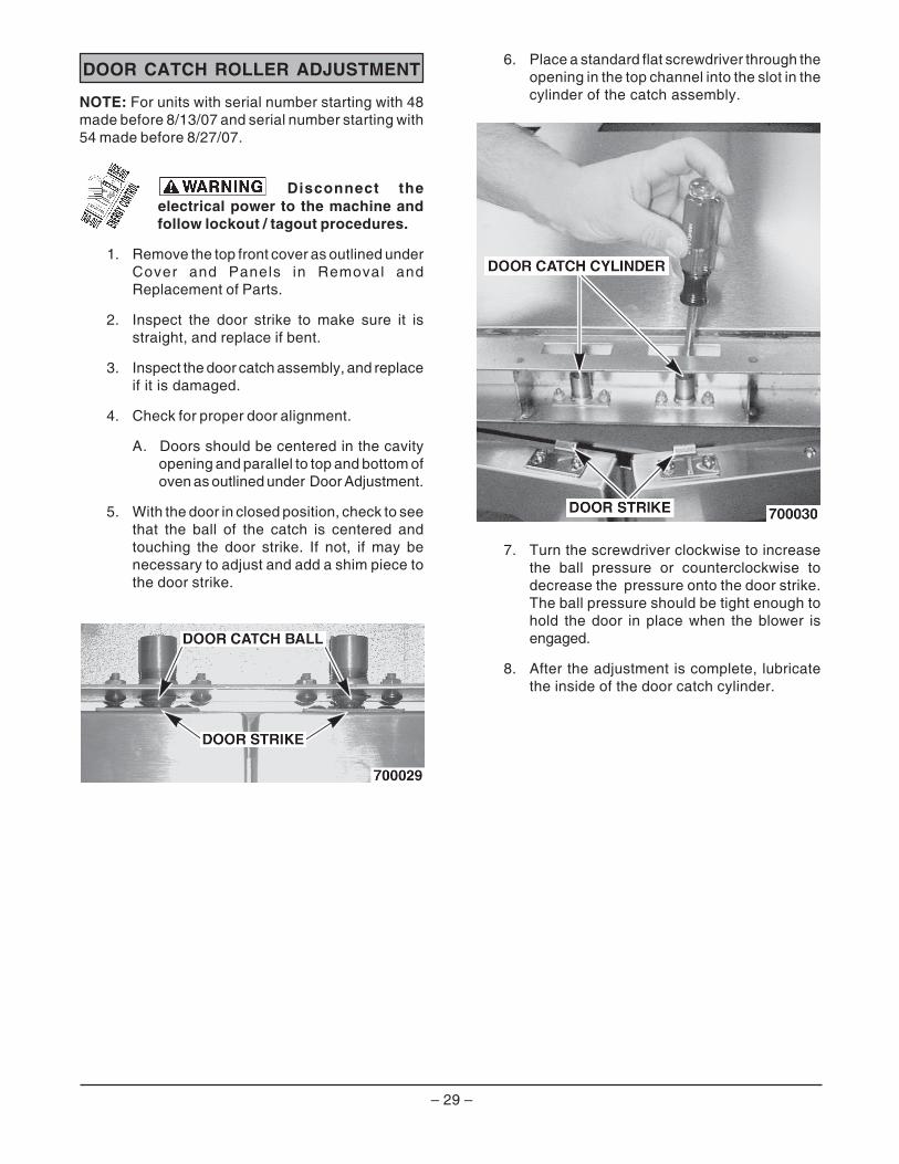
6. Place a standard flat screwdriver through theopening in the top channel into the slot in thecylinder of the catch assembly.
7. Turn the screwdriver clockwise to increasethe ball pressure or counterclockwise todecrease the pressure onto the door strike.The ball pressure should be tight enough tohold the door in place when the blower isengaged.
8. After the adjustment is complete, lubricatethe inside of the door catch cylinder.
DOOR CATCH ROLLER ADJUSTMENT
NOTE: For units with serial number starting with 48made before 8/13/07 and serial number starting with54 made before 8/27/07.
Disconnect theelectrical power to the machine andfollow lockout / tagout procedures.
1. Remove the top front cover as outlined underCover and Panels in Removal andReplacement of Parts.
2. Inspect the door strike to make sure it isstraight, and replace if bent.
3. Inspect the door catch assembly, and replaceif it is damaged.
4. Check for proper door alignment.
A. Doors should be centered in the cavityopening and parallel to top and bottom ofoven as outlined under Door Adjustment.
5. With the door in closed position, check to seethat the ball of the catch is centered andtouching the door strike. If not, if may benecessary to adjust and add a shim piece tothe door strike.
– 30 –
ELECTRICAL OPERATION
Master Switch (S1) - Determines the mode ofoperation; ON, OFF or OVEN COOL
Lights Switch (S2) - Controls the oven cavity lights.
Fan Speed Switch Hi/Low (S3) - Controls blowermotor speed between HI and LOW settings. Availableon models SG4D/SG6D.
Alarm/Buzzer - Signals the end of the normal cookcycle when cooking time expires.
Timer - Times the cooking cycle and signals thebuzzer at the end of the cycle.
Door Switch - Allows the oven to operate when thedoors are closed but stops the oven from operatingwhen the doors are opened.
Blower Motor - Operates the oven cavity blower.Also, an internal centrifugal switch on the motor isutilized to allow the connection of power to the heatrelay when the motor is at operating speed.
Transformer (T1) - Provides 24 VAC power to theignition control module and heating circuit.
Motor Control Relay(s) (SG4C/SG6C) - Providespower to HI and LOW speed motor windings based onoperator requirements.
Solid State Temperature Controller(SG4D/SG6D) - Monitors temperature sensor andregulates the oven cavity temperature by controllingthe heat relay through the blower motor centrifugalswitch contacts.
Ignition Control Module - Provide ignition spark andmonitors burner(s) flame current during ignitionsequence.
Ignition Electrode and Flame Sense Device - Ignitesthe gas and senses the presence of a flame. Theflame presence generates a micro-amp flame sensecurrent that is monitored by the ignition control module.A flame sense current of 1 micro amp (minimum andstable) is required to maintain burner ignition.
Power On Light (SG4D/SG6D) - Lit whenever theMaster Switch (S1) is turned to ON or OVEN COOLmode.
Heat Light - Lit whenever temperature controller iscalling for heat.
COMPONENT DESCRIPTIONNo Ignition Light (SG4C/SG6C) - Lit when power isturned ON, during ignition trial and gas purge time andwhen no flame is detected by flame sensor. If theoven fails to ignite after three attempts, it will remainlit until power is reset.
Temperature Probe (SG4D/SG6D) - This temperatureprobe is a thermistor device. A thermistor is a calibratedresistor which changes resistance with thetemperature. As the temperature increases, theresistance of the thermistor decreases. The resistanceof the probe is compared to the resistance of thetemperature controller resistor in to control andmaintain temperature.
Temperature Probe (SG4C/SG6C) - This temperatureprobe is a J-type thermocouple. As the temperatureincreases, a DC voltage is generated within thisthermocouple and compared to a list of temperaturevalues stored within the cooking computer memory tocontrol and maintain temperature.
High Limit Thermostat - Protects the oven fromtemperatures above 550°F by removing power fromthe first valve (safety) on the dual solenoid gas valvewhich stops the flow of gas to the burner. Auto resetsat 500°F.
Gas Valve (Dual Solenoid) - Contains two valves.The first valve is opened when the unit is turned onand the limit temperature is not exceeded. The secondvalve is turned by the heating system. Both valvesmust be open in order to get gas to the main burners.
SSR1 and SSR2 (SG4C/SG6C) - When SSR1 isenergized, it connects power to the blower motor forHI fan speed operation. When SSR2 is energized, itconnects power to blower motor for LOW speedoperation.
Cooling Fan - Circulates cooler air from rear of ovenforward to cool components in the control area.
Computer Control (SG4C/SG6C) - Monitorstemperature sensor and regulates the oven cavitytemperature by controlling the heat relay (R1) throughthe blower motor centrifugal switch contacts. Also,counts the time of the product and signals theelectronic alarm at the end of the cook cycle.
Power Level Control - Selects the percent of heatinput between 22% and 100%. Power level must beon for oven to work.
– 31 –
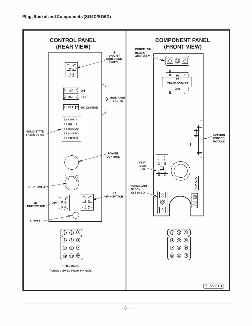
Plug, Socket and Components (SG4D/SG6D)
CONTROL PANEL(REAR VIEW)
COMPONENT PANEL(FRONT VIEW)
PORCELAINBLOCKASSEMBLY
PORCELAINBLOCKASSEMBLY
(PLUGS VIEWED FROM PIN SIDE)
21 3
54 6
87 9
1110 12
23 1
56 4
89 7
1112 10
OUT
BUZZER
ON
HEAT
NO IGNITION
INDICATORLIGHTS
N HIN1T
TRANSFORMER
1 4
5 8
9 12
13 14N H
HEATRELAY
(R3)
GR
OU
ND
IGNITIONCONTROL MODULE
1SON/OFF/
COOLDOWNSWITCH
3SFAN SWITCH
COOK TIMER
2SLIGHT SWITCH
SOLID STATETHERMOSTAT
POWERCONTROL
1P (FEMALE)
12
45
3 6
1
1 1LT
2LT1
2
2
2
3 LT1 2
45
3 6
1
1
24
4
5
3
3
6
5 COM 6
3 NO 7
2 (COM AC)
4 (120VAC)
9 (240VAC)
PL-56081-1

– 32 –
Plug, Socket and Components (SG4C/SG6C)
23 1
56 4
89
1 2 NO IGNITION
2J (FEMALE)
2J
3J
3J (FEMALE)
PIN NUMBERS
CONTROL PANEL(REAR VIEW)
COMPONENT PANEL(FRONT VIEW)
1LT
41
52
61
107
2221 2423
1817 2019
1413 1615
109 1211
65 87
21 43
118
1297
1 2 3
4 5 6
7 8 9
10 7 4
11 8 5
12 9 6
1
2
3
OPER. TEMP.
0-30 DEG. C
1 EVENT 2 OUT2 EVENT 1 OUT3 EVENT COM (IN)4 EVENT 1 (IN) 5 EVENT 4 OUT6 EVENT 3 OUT7 NOT USED8 POWER 5V9 EVENT 2 (IN)
1 NOT USED 7 NOT USED 2 SSRI 8 NOT USED 3 SSRI 9 L2 24V- 4 NOT USED 10 NOT USED 5 NOT USED 11 NOT USED 6 L1 24V- 12 NOT USED
1
1 NOT USED2 TC
5 NOT USED6 NOT USED
3 TC J TYPE (RED)4 NOT LISTED
2 3 4 5 6
+-
COMPUTERCONTROLLER
PORCELAINBLOCKASSEMBLY
2SLIGHT
SWITCH
1SON/OFF/
COOLDOWNSWITCH
ELECTRONIC BEEPER
1P (MALE)
2P (MALE)
(PLUGS VIEWED FROM PIN SIDE)
(PLUGS VIEWED FROM PIN SIDE)
3P (MALE)
1J (FEMALE)
2324 2122
1920 1718
1516 1314
1112 910
78 56
34 12
PL-56082
21
34
LOAD
OUT
N HIN
1TTRANSFORMER
INPUT
21
1 4
5 8
9 12
13 14N H
34
LOAD
INPUT
HEATRELAY
(R1)
GR
OU
ND
GROUND
SOLID STATERELAY (SSR1)
SOLID STATERELAY (SSR2)
IGNITIONCONTROL MODULE
PORCELAINBLOCKASSEMBLY

– 33 –
2. Set temperature controller dial to desiredtemperature.
A. Contacts J3 and J5 close.
3. Power switch (S1) is turned ON.
NOTE: Power is available to the oven light switch
A. Component cooling fan energized.
B. ON light (amber) is lit.
C. Power to timer terminal C.
D. Transformer (T1) energized.
1) Power (24 VAC) to one side of thefollowing components: heat relay (R3)normally open (N.O.) contact.
2) First valve (safety) on the gas valveenergized. Gas does not flow to theburner until the 2nd valve (main) isenergized.
3) Ignition module energized.
E. Heating light is lit.
F. Power to one side of centrifugal switch.
G. Convection fan motor is energized through(S3) high-low.
1) When the convection fan motorreaches operat ing speed, thecentrifugal switch (N.O.) on the motorcloses.
H. Heat relay is energized.
1) N.O. contacts close.
SEQUENCE OF OPERATIONS
SG4D/SG6D with Solid State TemperatureController
Schematic 424373-1 will be used to explain theelectrical sequence of operation.
Cook Cycle
1. Conditions
A. Oven connected to correct voltage.
1) L1 (HOT) to power switch (S1).
2) L2 (neutral or second line) to oneside of the following components: L1of the power level control, power ONlight, heat light, temperature controllerboard terminal 9 (120VAC) or terminal10 (208-240 VAC), oven cavity lights,buzzer, timer motor, heat relay coil(R3), convection fan motor common(C), transformer primary T1), motorspeed (Hi/Low) relay coil (R1), holdrelay coil (R2) and the componentcooling fan.
B. Oven properly grounded.
C. Gas supply valve ON.
D. Gas combination control valve ON.
E. Power switch (S1) OFF.
F. Oven light switch (S2) ON/OFF (positionhas no affect on the function of thenormal cooking cycle).
G. Temperature controller dial set to lowesttemperature (fully counterclockwise).
H. High limit switch closed (position has noaffect on the function of the normalcooking cycle).
I. Timer in the OFF position.
J. Oven doors closed.
K. Door switch contacts closed.
L. Oven cavity temperature below 140°F.
M. Power level switch to 100%.
(Continued next page)
– 34 –
4. Heating circuit is powered.
A. No ignition light (red) comes ON.
B. Module performs a self diagnostic testfor 4 seconds.
C. Second valve (main) on the gas valve isenergized. Gas starts to flow to burners.
D. Sparking begins, the no ignition lightgoes out and burners light.
NOTE: Sparking continues for up to 7 seconds or untila flame is established on both burners. If a flame issensed on both burners, the no ignition light stays outand burner remains lit. If a flame is not sensed on bothburners after 7 seconds of sparking, the no ignitionlight comes back on, second valve (main) on the gasvalve is de-energized and gas flow to the burnerstops. Ignition trial cycle repeats after a 15 secondpurge between cycles for two additional tries beforelocking out. To reset after a lockout, turn powerswitch (S1) OFF then ON.
5. Oven reaches set temperature.
A. Temperature controller de-energizesinternal relay and the normally open (N.O.)contacts open.
1) Heat light goes out.
B. Power removed from heat relay.
C. Heat relay normally open (N.O.) contactsOPEN.
D. Power removed from heating circuit.
1) Second gas valve de-energized.
6. The oven will continue to cycle on thetemperature controller until the doors areopened or master switch (S1) is turned to theOFF or OVEN COOL position.
Timer Cycle
The timer operates independently of the heatingcycle. Additional time can be set or the timer can beturned OFF throughout the cooking cycle.
1. With the master switch turned ON, power issupplied to timer.
A. Set the timer to desired time.
B. Contacts 1 & 3 close, timer motor isenergized and timing down begins.
2. Time expires on timer.
A. Contacts 1 & 3 open, timer motor isde-energized and timing stops.
B. Contacts 1 & 4 close.
1) Buzzer energized and sounds. Thebuzzer continues to sound until thetimer dial is set to the OFF positionor additional time is set.
Cool Down Cycle (Solid State TemperatureController)
1. Conditions.
A. Oven is ON.
B. Oven cavity temperature needs to belowered.
C. Doors are open.
1) Convection fan de-energized.
2) Thermostat de-energized.
a. Heat light out.
b. Power removed from heat relay.
3) 24 V transformer de-energized.
4) Cooling fan de-energized.

– 35 –
2. Power switch (S1) turned to COOL DOWN.
A. Power to fan speed switch (S3). Set fanspeed switch to either HI or LO.
3. If door is closed, power is supplied to oneside of the following components:
A. Power ON light (Amber) comes ON.
B. Transformer (T1) energized.
1) Power (24 VAC) to one side of thefollowing components: heat relay (R3)normally open (N.O.) contacts, highlimit connected through the normallyclosed (N.C.) contacts to the firstvalve (safety) on the dual solenoidgas valve.
a. First valve (safety) on the gasvalve energized. Gas does notflow to the burner until the secondvalve (main) is energized.
C. Component cooling fan.
D. Power to timer and oven cavity lights.
4. The oven will remain in this condition until themaster switch (S1) is turned to the OFF or ONposition.
SG4C/SG6C with Computer Controller
Schematic 426575-1 will be used to explain theelectrical sequence of operation.
Normal Cook Cycle
1. Conditions
A. Oven connected to correct voltage.
1) L1 (hot) to power switch (S1).
2) L2 (neutral or second line) to one sideof the following components: ovencavity lights, convection fan motorcommon (C), transformer primary(T2), component cooling fan and theheat relay coil (R1).
B. Oven properly grounded.
1) Ground (GND) to one side of thefollowing components: computercontrol case, no ignition light,transformer secondary (T2), ignitioncontrol module, the first valve (safety)and second valve (main) on the dualsolenoid gas valve and computercontrol pin 9 (C3-9).
C. Gas supply valve ON.
D. Gas combination control valve ON.
E. Power switch (S1) OFF.
F. Computer control is set up properly andready to use.
G. Oven lights switch (S2) ON or OFF(position has no affect on the function ofthe normal cook cycle).
H. High limit thermostat closed.
I. Oven doors closed.
J. Oven cavity temperature below 140°F.
2. Power switch (S1) turned ON.
A. Power (120 VAC) to computer control pin3 (C3-3). Power at pin 3 is not transferredto other components until computercontrol is energized and operationconditions are met.
B. Power is available to the oven light switch(S2).
– 36 –
C. Power to terminal 1 on solid state relay 1SSR1-load side and solid state relay 2SSR2-load side.
D. Component cooling fan energized.
E. Transformer (T1) is energized, 24 voltoutput.
1) Power (24 VAC) to one side of thefollowing components: heat relay (R1)normally open (N.O.) contacts, highlimit connected through the normallyclosed (N.C.) contacts to the firstvalve (safety) on the dual solenoidgas valve.
2) First valve (safety) on the gas valveenergized. Gas does not flow to theburner until the second valve (main)is energized.
3) Ignition module energized.
4) Power (24 VAC) to the oven computercontrol.
3. Control is energized and performs a power onself test before energizing outputs. If thecontrol passes self test, then the outputs areenergized and operation sequence continues,If control does not pass self test, then thecorresponding error code is displayed.
NOTE: Control retains last temperature set.
A. Computer control senses oven cavitytemperature.
1) With the oven cavity temperaturebelow set point, the controls120 VAC output from pin C3-2 isactivated and power is connected tothe common (C) side of the blowerswitch contacts on the convectionfan motor.
2) The controls 5 VDC output from pinsC2-2 (-) and C2-8 (+) is activated andSSR1 relay is energized.
a. Convection fan motor isenergized (fan speed on HI).
3) When the convection fan motorreaches operating speed:
a. The blower switch (N.O.) on themotor closes.
B. Heat relay coil (R1) energized.
1) (R1) contacts (N.O.) close and theheating circuit is powered.
2) Oven heat light on the control comeson.
C. Ignition module is energized.
1) Heating circuit is powered.
2) No ignition light (red) comes ON.
3) Module performs a self-diagnostictest for 4 seconds.
4) Second valve (main) on the gas valveis energized. Gas starts to flow toburners.
5) Sparking begins, the no ignition lightgoes out and burners light.
NOTE: Sparking continues for up to 7 seconds or untila flame is established on both burners. If a flame issensed on both burners, the no ignition light stays outand burner remains lit. If a flame is not sensed on bothburners after 7 seconds of sparking, the no ignitionlight comes back on, second valve (main) on the gasvalve is de-energized and gas flow to the burnerstops. Ignition trial cycle repeats after a 15 secondpurge between cycles for two additional tries beforelocking out. To reset after a lockout, turn powerswitch (S1) OFF then ON.
4. Oven reaches set point temperature.
A. Computer control deactivates the120 VAC output to heat relay (R1).
1) Heat relay (R1) de-energized and thenormally open (N.O.) contacts open.
B. Power removed from ignition controlmodule.
1) The second valve (main) on the gasvalve is de-energized and gas flow tothe burner stops.
– 37 –
2) Oven heat LED on the control goes out.
3) Oven ready LED on the control comesON.
4) Electronic beeper sounds momentarily.
C. The oven will continue to cycle on thecomputer control until the doors are openedor power switch (S1) is turned to the OFF orCOOL DOWN position.
Temperature and Time Cycle (Normal Cooking)
The computer's internal cook timer operatesindependently of the heating cycle. Additional timecan be set or the timer can be stopped and restartedthroughout the cooking cycle.
Refer to the Installation & Operation Manual forspecific operation instructions of the oven computercontrol.
Function Switch SG4C/SG6C - Selects the cookingmode of the oven between Cook or Roast and Hold.Is used in conjunction with the Roast and Hold timerduring Roast and Hold cooking. The selected modealso determines the fixed blower speed: HI for Cookand LO for Roast and Hold.
If Roast and Hold is selected, when the Roast (thenhold) time expires, the oven heating stops and theoven enters the hold mode. Once the even cavitytemperature drops to 150°F, the heat comes back onand the oven cycles at this temperature to hold thecooked product.
Roast and Hold Cycle
For a detailed explanation of the Roast and Holdmode, refer to the instructions manual.
In the Roast and Hold mode, the operation of thecomputer control is identical to the normal cookcycle, with these exceptions:
1. Oven Roast and Hold light on the controlcomes ON.
2. Convection fan speed changes from HI toLO.
A. The computer control 5 VDC output frompins C2-2 (-) and C2-8 (=) is deactivatedand SSR1 relay is de-energized.
1) Power (120 VAC) is removed fromconvection fan motor high speedterminal.
B. The computer control 5 VDC output frompins C2-1 (-) and C2-8 (+) is activated andSSR2 relay is energized.
1) Power (120 VAC) is applied to theconvection fan motor low speedterminal.
3. At the end of the cook time, the electronicbeeper sounds momentarily to indicate theend of the first stage cooking (oven operatesnormally at the temperature and time selecteduntil time expires).
4. The display flashes HOLD as the oven entersthe hold mode. This is also considered secondstage cooking (oven heating stops but productcontinues to cook on residual heat).
A. Convection fan motor is de-energized.
B. Oven fan cycles with the output of theheating system. Anytime the systemcalls for heat, the fan must be running.After the oven has reached the 150°F settemperature, the heat and fan are de-energized.
5. After the oven temperature drops below 150°F,the heat comes back on and cycles as neededto maintain the hold temperature of 150°F.
A. Convection fan motor energized.
6. The oven continues to cycle in this manneruntil one of he following occurs:
A. The cook and hold mode is turned OFF.
B. Power switch (S1) is turned to the OFF orCOOL DOWN position.
– 38 –
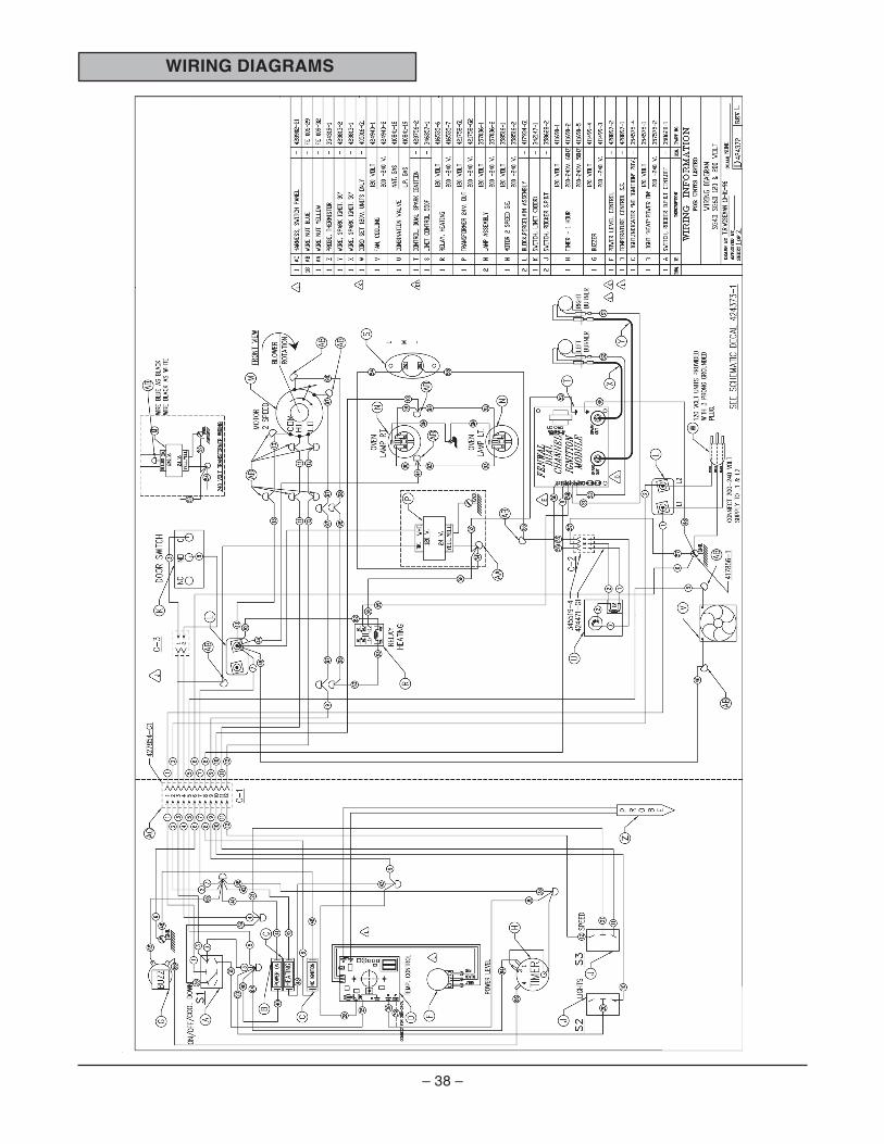
WIRING DIAGRAMS

– 39 –
WIR
ING
DIA
GR
AM
734
CO
MP
UT
ER
CO
NT
RO
LD
UA
L B
UR
NE
R C
ON
VE
CT
ION
OV
EN
S 1
20 &
200
V.
4
2657
4
Rev
. C

– 40 –
SCHEMATICS
POWER LEVEL
C1-3
C1-4
C3-1
C3-2
OPEN
DOORSWITCH
PROBE
C1-6
NO IGNITION
HEAT RELAY
C
MBK
NCHOLD
BUZZER
WHT. LEAD
1 HOUR TIMER
NO
FROM FRONTROTATION
HEATING
THERMOSTAT
POWER ON
SHOWN ON
ON/OFF/COOL
C2-3
C2-1
C2-2
1st VALVE
TH
GND.24V.
CHANNELDUAL
RED
YELLOW
BLUE
YELLOW24V.
T2
BLACK
C1-8
NC
T1
2ed VALVE
V1
MODULEIGNITION
550 FLIMIT
RELAYHEAT
YELLOW YELLOW GND.24V.
USE BLACK FOR WHITEUSE BLUE FOR BLACKFOR 240V.
WHITEBLACK
2-SPEEDFAN MOTORCONVECTION
LO
HICOM.
C1-12
C1-11
C1-9
C1-5
OVEN LAMP
OVEN LAMPC1-10
C1-1
40W
40W
C1-7C1-2
GND.
REV D
L2L1200-240V
120 VOLT
S1
S2
S3
GAS CONVECTION OVEN SG4 WITH STD. CONTROL424373-1
COOLING FAN
SWITCHFAN SPEED
LOW
HIGH
OVEN LAMP SWITCH
POWER SWITCH
WHITEBLACK
3
8
35
39
6
88
28
64 66 65
9293
36
21
98
97
4
7
4243
39
35
4140
3
55
56
56
55
5958
48
8
57
54
52
7
13
12
11
12
11
9
9
5
9092
9091
5 46
6
101020
1
36
1
44
2
2

– 41 –
GAS CONVECTION OVEN SG4 WITH WATLOW 734 CONTROL426575-1 REV. C

– 42 –
TROUBLESHOOTING
SMOTPMYS SESUACELBISSOP
roLOOCNEVOninurt'nseodrotomrewolB.noitisopNO
.egatloveniL.noitcnuflamhctiwsretsaM/rewoP
.noitcnuflamhctiwsnaF.noitcnuflamgniriwnoitcennocretnI
.noitisopNOehtninurt'nseodrotomrewolB.KOsnoitcnufnwoDlooC
.noitcnuflamhctiwsrooD.evitareponistcatnochctiwsretsaM/rewoP
.noitcnuflamgniriwgnitcennocretnI
LOOCNEVOninurt'nseodrotomrewolB.noitisopNOniKOsnuR.noitisop
.noitcnuflamhctiwsretsaM/rewoP.noitcnuflamgniriwnoitcennocretnI
.etingitonseodsaG.krapsoN
.NOtonsithgilnoitingIoN
.esnesemalf/retinginoedortceledetrohS.NEPO)egatlovhgih(elbacretingI
.noitcnuflamyalertaeH.evitareponirotomrewolbnihctiwslagufirtneC
.evitareponiremrofsnarT.nepotatsomrehttimilhgiH
.noitcnuflamgniriwgnitcennocretnI.noitcnuflameludomnoitingI
.etingitonseodsagtubskrapS
.evitareponiroffoevlavdionelossaG.desolcevlavsaglaunaM
.erusserpsagtneiciffusniroFFOylppussaG.noitcnuflamgniriwgnitcennocrenI
.noitcnuflameludomnotingI
.emalfniatniamtonlliwtubsetingisaG
.noitcnuflamsnoitcennocdaelretingI.evitareponidnuorgretingI
.detsujdalamronoitcnuflamesnesemalf/retingI.erusserpsagtneiciffusnI
.gnissimrodetcurtsbo,deggulptnevlekronS.eludomnoitingiotremrofsnartmorfytiraloptcerrocnI
.taehwolroevissecxE
.noitcnuflameborperutarepmeT.noitcnuflamdraoblortnocerutarepmeT
.tneiciffusnierusserpsaG.detcurtsborodeggulpecifirosaG
.wolottesebyamlevelrewoP

– 43 –
TROUBLESHOOTING
COMPUTER CONTROL MODELS ONLY
MOTPMYS SESUACELBISSOP
.taehtonseodnevO
.nepohctiwstimilhgiH.noitcnuflameborP
.noitcnuflamlortnoC.ffootteslortnoclevelrewoP
.renrubsagffognittuhstatsomrehttimilhgiH.noitcnuflameborP
.noitcnuflamlortnoC
.hguonetohtonnevO.noitcnuflameborP
puteSeeS.wolotgnittes)1Hr(hgihegnarlortnoC.)C6GS/C4GS(rellortnoCretupmoCrednuedoM
SMOTPMYS SESUACELBISSOP
gninoitcnuftonroevitareponiremitlacinahceM.ylreporp
.noitcnuflamgniriwgnitcennocretnI.tcerrocniegatloveniL
.noitcnuflamremiT
.nurtonseodnafgnilooctnenopmoC.elbareponirotoM
.noitcnuflamgniriwgnitcennocretnI
.gnikoocnevenU
.noitcerid/deepsrotomnafnoitcevnoC.noitsubmocrooP
.tcerrocnierusserpsaG.detcurtsborodeggulptnevtsuahxE.detcurtsborodeggulptnevlekronS.degamadrognissimselffabwolfriA
.smelborptnettimretnIserutarepmettneibmahgiH
.esoolsnoitcennocgniriW.noitcnuflamnafgnilooC
.rellortnocerutarepmetotrewopoN.noitisopLOOCNEVOnihctiwsretsaM/rewoP
.nepohctiwsroodrorooD
.gnihsalfsirellortnocehtnoDEL;taehoN .detrohsronepoeborP

– 44 –FORM 35626 Rev. A (02-08) PRINTED IN U.S.A.
ERROR CODES
DNAEDOCMELBORP
ESUACELBABORP NOITULOS
kcehcMOR-10rErorremus
noitcnuflamMORlanretnI .rewopelcyC
kcehcMAR-20rErorremus
noitcnuflamMARlanretnI .rewopelcyC
rosnestneibmA-30rErorre
F°23wolebsierutarepmettneibmA .lortnocehttaerutarepmettneibmakcehC
noitarugifnoC-40rErorre
noitcnuflamrossecorporciM .rewoPelcyC
rorremorpEE-5orE atadgnirotselihwssolrewoP .rewoPelcyC
D/A1enoZ-60rErorrewolfrednu
· epytrosnestcerrocnI· edistuoerutarepmetgnirusaeM
egnarrosneseht
· tahtyfireV.retemarapputes1PnIehtkcehC.rosnesehtsehctamti
· arofsnoitcennocdnarosneskcehCnoitidnocehtfI.rosnesneporodesrever
lliwrorreeht,devlosersirorreehtgnisuac.raelc
D/A1enoZ-70rErorrewolfrevo
rosnesnepO
· tahtyfireV.retemarapputes1PnIehtkcehC.rosnesehtsehctamti
· arofsnoitcennocdnarosneskcehCnoitidnocehtfI.rosnesneporodesrever
lliwrorreeht,devlosersirorreehtgnisuac.raelc
wolfrevokcatS-01rErorre
noitcnuflamrossecorporciM· .rewoPelcyC· arofsnoitcennocdnarosneskcehC
.rosnesneporodesrever
rosnesnepO-11rErorre
rosnesnepO
· tahtyfireV.retemarapputes1PnIehtkcehC.rosnesehtsehctamti
· arofsnoitcennocdnarosneskcehC.rosnesneporodesrever
rosnesdetrohS-21rE· epytrosnestcerrocnI· edistuoerutarepmetgnirusaeM
egnarrosneseht
· tahtyfireV.retemarapputes1PnIehtkcehC.rosnesehtsehctamti
· arofsnoitcennocdnarosneskcehC.rosnesneporodesrever


![CALIFORNIA [ADVANCE RELEASE] · Sh Sh MgCp SG SG SG SG SG SG SG SG SG Fe Fe Gr-s Gr-s Per CS Pum Pum Salt Salt Salt S-o S-o Zeo Dia Bent Bent Bent B B Clay Clay Dia DS DS DS DS DS](https://img.pdfslide.net/doc/110x75/5d435e0888c993ea558bc1de/california-advance-release-sh-sh-mgcp-sg-sg-sg-sg-sg-sg-sg-sg-sg-fe-fe-gr-s.jpg)