Embed Size (px)
Citation preview

ETIN70 – Modern Electronics: F11 – Feedback and Stability
Reading GuideOutline
Problems
Sedra/Smith 7ed int
Sedra/Smith 7ed int
F11 – Feedback and Stability
1
• Chapter 10.1-4, 10.6 (voltage feedback)
• (Chapter 10.5 (other feedback))
• Chapter 10.7-9 (amplifier stability)
• (Chapter 10.10 (freq. compensation))
Lars Ohlsson
• P10.7, 10.8, 10.17, 10.28, 10.30
• General feedback structure and systematic analysis
• Feedback topologies
• Feedback voltage amplifier (series-shunt)
• Feedback transconductance amplifier (series-series)
• Feedback transresistance amplifier (shunt-shunt)
• Feedback current amplifier (shunt-series)
• Stability considerations and Nyquist plot
• Effects of feedback on pole location
• Stability analysis using Bode plots, gain and phase margin
• Frequency compensation (pole splitting)
2018-10-09

ETIN70 – Modern Electronics: F11 – Feedback and Stability
General Negative Feedback Structure
• Open loop gain, 𝐴
• Feedback factor
(feedback transfer function), 𝛽
• Loop gain
(loop transfer function), 𝐴𝛽
• Signal gain from 𝑥𝑖 to 𝑥𝑓
• Always dimensionless
• Amount of feedback, 1 + 𝐴𝛽
• Gain with feedback
(closed loop transfer function), 𝐴𝑓 =𝑥𝑜
𝑥𝑠=
𝐴
1+𝐴𝛽
2
Transfer function is a more general term,
non-scalar, for signal gain or factor.
𝑥𝑜 = 𝐴𝑥𝑖𝑥𝑓 = 𝛽𝑥𝑜
𝑥𝑖 = 𝑥𝑠 − 𝑥𝑓𝑥𝑓
𝑥𝑖= 𝐴𝛽

ETIN70 – Modern Electronics: F11 – Feedback and Stability
Benefits of Feedback
• Gain with feedback is reduced by the
amount of feedback, 1 + 𝐴𝛽
• The amount of feedback also quantifies…
• Gain desensitivity
• Bandwidth extension
• Reduction of nonlinear distortion
• Input resistance idealisation
(increase/ decrease)
• Output resistance idealisation
(increase/ decrease)
• Interference reduction
3
Feedback improvements come at the cost of gain,
and at the risk of instability.
𝐴𝑓 =𝐴
1 + 𝐴𝛽
ETIN70 – Modern Electronics: F11 – Feedback and Stability
Benefits of Feedback
• Gain desensitivity
• Bandwidth extension
• Reduction of nonlinear distortion
• Interference reduction
• Input resistance idealisation
(increase/ decrease)
• Output resistance idealisation
(increase/ decrease)
4
𝐴𝑓 =𝐴
1 + 𝐴𝛽
Feedback improvements come at the cost of gain,
and at the risk of instability.

ETIN70 – Modern Electronics: F11 – Feedback and Stability
Ideal Feedback Analysis
• Quantification method
• Cancel source, break loop, inject test signal, and measure return
• Sign of the loop gain
• Negative feedback: 𝐴𝛽 > 0
• Positive feedback: 𝐴𝛽 < 0 (reduced stability)
• Magnitude of the loop gain, 𝐴𝛽
• Determines amount of feedback, 1 + 𝐴𝛽 ,
and ideality of closed loop gain
• Amount of feedback quantifies the benefits of feedback
5
𝐴𝑓 =𝐴
1 + 𝐴𝛽, ቚ𝐴𝑓
𝐴𝛽≫1≈1
𝛽
Feedback loop does not load amplifier, no
internal feedback, and unilateral blocks.
𝑥𝑠 = 0𝑥𝑟 = −𝐴𝛽𝑥𝑡
𝐴𝛽 =−𝑥𝑟𝑥𝑡

ETIN70 – Modern Electronics: F11 – Feedback and Stability
Where did we already encounter feedback?
6

ETIN70 – Modern Electronics: F11 – Feedback and Stability
Examples of Series-Shunt (Voltage) Feedback Amplifiers
• Amplifier circuit
• Some kind of circuit with gain,
preferably voltage amplifier
• Voltage feedback network
• Series voltage mixing
on input
• Shunt voltage sampling
over output
7
The feedback network is treated
as an add-on to the amplifier.

ETIN70 – Modern Electronics: F11 – Feedback and Stability
Loop (Voltage) Gain Analysis
• Identify feedback network
• Determine feedback factor, 𝛽
• Determine ideal gain with feedback (closed loop gain)
• Determine loop gain
• Cancel source signal
• Break loop (ideally at infinite impedance)
• Terminate return path (as required)
• Apply a test voltage to the feedback loop
• Measure the returned termination voltage
• Determine the open loop gain from
feedback factor and loop gain
8
𝐴𝑓 =𝐴
1 + 𝐴𝛽≈1
𝛽
𝐴 =𝐴𝛽
𝛽
𝐴𝛽 = −𝑉𝑟𝑉𝑡

ETIN70 – Modern Electronics: F11 – Feedback and Stability
Sensing, Mixing, and Feedback Topology
• Mixing on the input
• Voltage (series) or current (shunt)
• Sensing on the output
• Voltage (shunt) or current (series)
• Feedback topologies
• Series-shunt (voltage)
• Series-series (transconductance)
• Shunt-shunt (transresistance)
• Shunt-shunt (current)
• Feedback network typically loads circuit
(not ideal probe and source)
9
The appropriate feedback topology
depends on amplifier type.
ETIN70 – Modern Electronics: F11 – Feedback and Stability
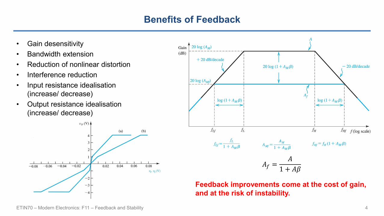
Series-Shunt Feedback Voltage Amplifier
• Series-shunt feedback
• Input
• Voltage mixing
• Increased input resistance
• Output
• Voltage sampling
• Reduced output resistance
10

ETIN70 – Modern Electronics: F11 – Feedback and Stability
BREAK
11
ETIN70 – Modern Electronics: F11 – Feedback and Stability
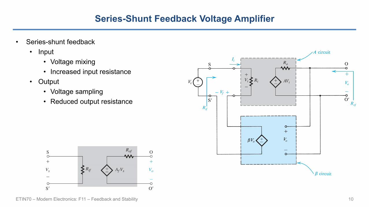
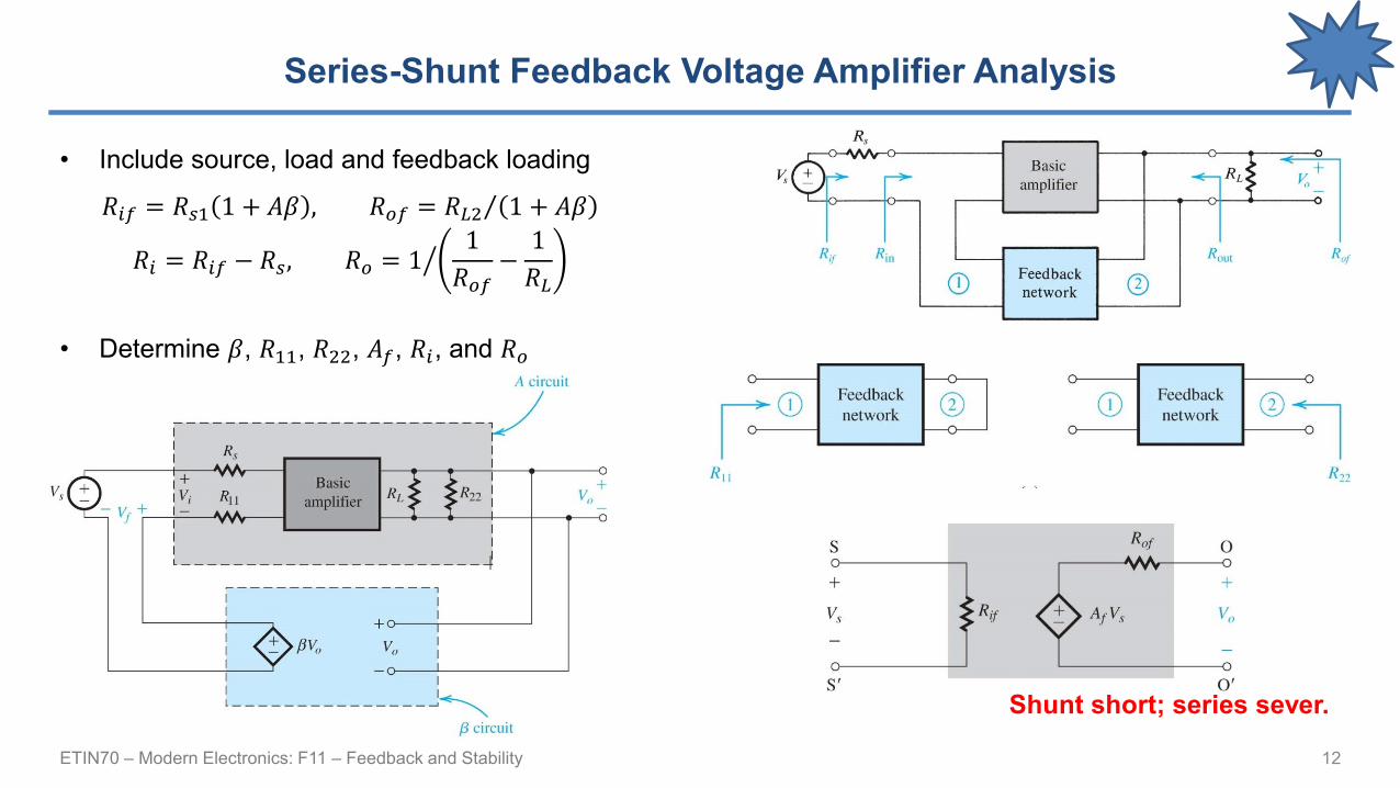
Series-Shunt Feedback Voltage Amplifier Analysis
• Include source, load and feedback loading
• Determine 𝛽, 𝑅11, 𝑅22, 𝐴𝑓, 𝑅𝑖, and 𝑅𝑜
12
𝑅𝑖𝑓 = 𝑅𝑠1 1 + 𝐴𝛽 , 𝑅𝑜𝑓 = Τ𝑅𝐿2 1 + 𝐴𝛽
𝑅𝑖 = 𝑅𝑖𝑓 − 𝑅𝑠, 𝑅𝑜 = ൗ11
𝑅𝑜𝑓−
1
𝑅𝐿
Shunt short; series sever.

ETIN70 – Modern Electronics: F11 – Feedback and Stability
(Series-Series Feedback Transconductance Amplifier)
• Series-series feedback
• Input
• Voltage mixing
• Increased input resistance
• Output
• Current sampling
• Increased output resistance
13
Shunt short; series sever.

ETIN70 – Modern Electronics: F11 – Feedback and Stability
(Shunt-Shunt Feedback Transresistance Amplifier)
• Shunt-shunt feedback
• Input
• Current mixing
• Reduced input resistance
• Output
• Voltage sampling
• Reduced output resistance
14
Shunt short; series sever.

ETIN70 – Modern Electronics: F11 – Feedback and Stability
(Shunt-Series Feedback Current Amplifier)
• Shunt-series feedback
• Input
• Current mixing
• Reduced input resistance
• Output
• Current sampling
• Increased output resistance
15
Shunt short; series sever.

ETIN70 – Modern Electronics: F11 – Feedback and Stability
An amplifier must be stable; why?
16
ETIN70 – Modern Electronics: F11 – Feedback and Stability
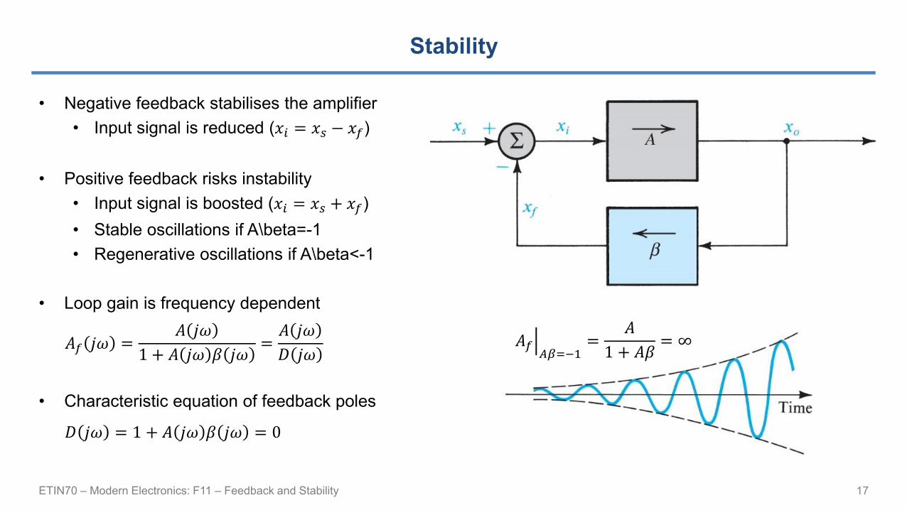
Stability
• Negative feedback stabilises the amplifier
• Input signal is reduced (𝑥𝑖 = 𝑥𝑠 − 𝑥𝑓)
• Positive feedback risks instability
• Input signal is boosted (𝑥𝑖 = 𝑥𝑠 + 𝑥𝑓)
• Stable oscillations if A\beta=-1
• Regenerative oscillations if A\beta<-1
• Loop gain is frequency dependent
• Characteristic equation of feedback poles
17
ቚ𝐴𝑓𝐴𝛽=−1
=𝐴
1 + 𝐴𝛽= ∞
𝐷 𝑗𝜔 = 1 + 𝐴 𝑗𝜔 𝛽 𝑗𝜔 = 0
𝐴𝑓 𝑗𝜔 =𝐴 𝑗𝜔
1 + 𝐴 𝑗𝜔 𝛽 𝑗𝜔=𝐴 𝑗𝜔
𝐷 𝑗𝜔
ETIN70 – Modern Electronics: F11 – Feedback and Stability
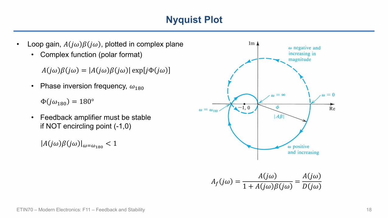
Nyquist Plot
• Loop gain, 𝐴 𝑗𝜔 𝛽 𝑗𝜔 , plotted in complex plane
• Complex function (polar format)
• Phase inversion frequency, 𝜔180
• Feedback amplifier must be stable
if NOT encircling point (-1,0)
18
𝐴𝑓 𝑗𝜔 =𝐴 𝑗𝜔
1 + 𝐴 𝑗𝜔 𝛽 𝑗𝜔=𝐴 𝑗𝜔
𝐷 𝑗𝜔
𝐴 𝑗𝜔 𝛽 𝑗𝜔 𝜔=𝜔180< 1
𝐴 𝑗𝜔 𝛽 𝑗𝜔 = 𝐴 𝑗𝜔 𝛽 𝑗𝜔 exp 𝑗Φ 𝑗𝜔
Φ 𝑗𝜔180 = 180°
ETIN70 – Modern Electronics: F11 – Feedback and Stability
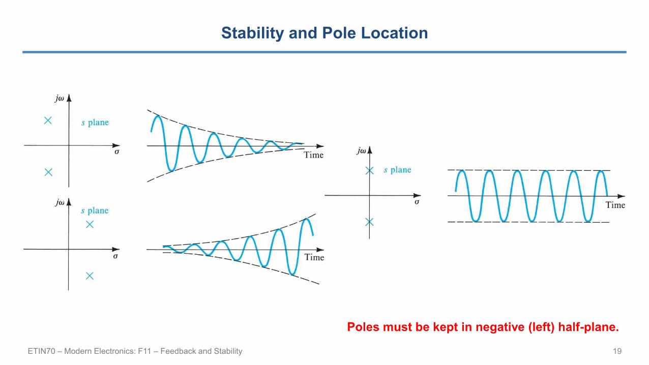
Stability and Pole Location
19
Poles must be kept in negative (left) half-plane.
ETIN70 – Modern Electronics: F11 – Feedback and Stability
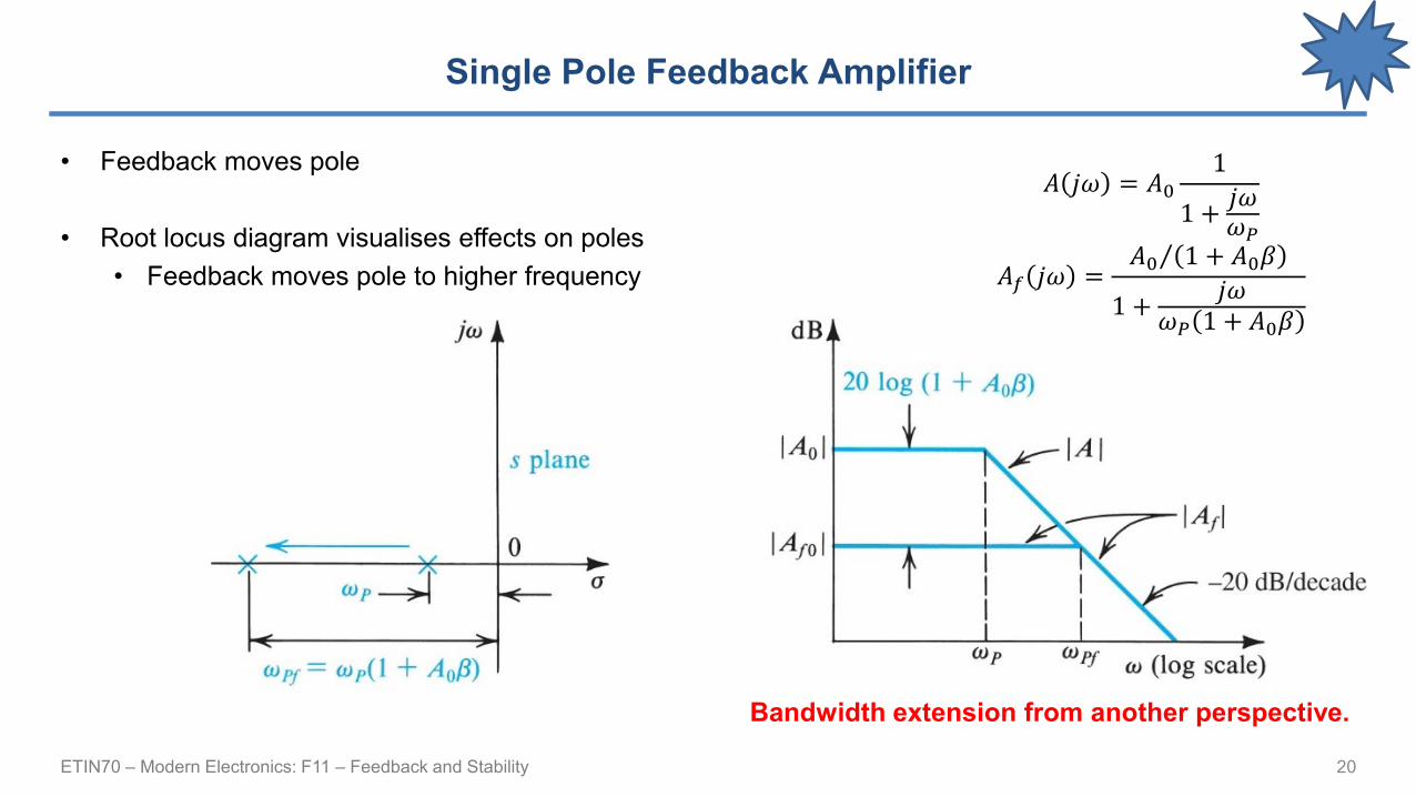
Single Pole Feedback Amplifier
• Feedback moves pole
• Root locus diagram visualises effects on poles
• Feedback moves pole to higher frequency
20
Bandwidth extension from another perspective.
𝐴 𝑗𝜔 = 𝐴01
1 +𝑗𝜔𝜔𝑃
𝐴𝑓 𝑗𝜔 =Τ𝐴0 1 + 𝐴0𝛽
1 +𝑗𝜔
𝜔𝑃 1 + 𝐴0𝛽

ETIN70 – Modern Electronics: F11 – Feedback and Stability
Two Pole Feedback Amplifier
• Feedback merges poles into a resonance
• Root locus diagram visualises effects on (two) poles
• Feedback first brings poles together, then
poles split into conjugate pair
21
ETIN70 – Modern Electronics: F11 – Feedback and Stability
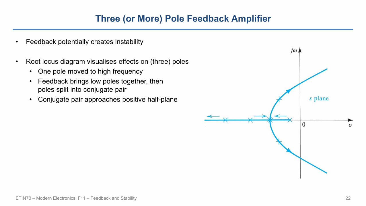
Three (or More) Pole Feedback Amplifier
• Feedback potentially creates instability
• Root locus diagram visualises effects on (three) poles
• One pole moved to high frequency
• Feedback brings low poles together, then
poles split into conjugate pair
• Conjugate pair approaches positive half-plane
22

ETIN70 – Modern Electronics: F11 – Feedback and Stability
Gain and Phase Margin
• “Destructive” positive feedback
• Loop gain with phase inversion
• Risk of oscillation (not an amplifier)
• Gain margin
• Evaluated at phase inversion
• Phase margin
• Evaluated at unity gain
23
ETIN70 – Modern Electronics: F11 – Feedback and Stability
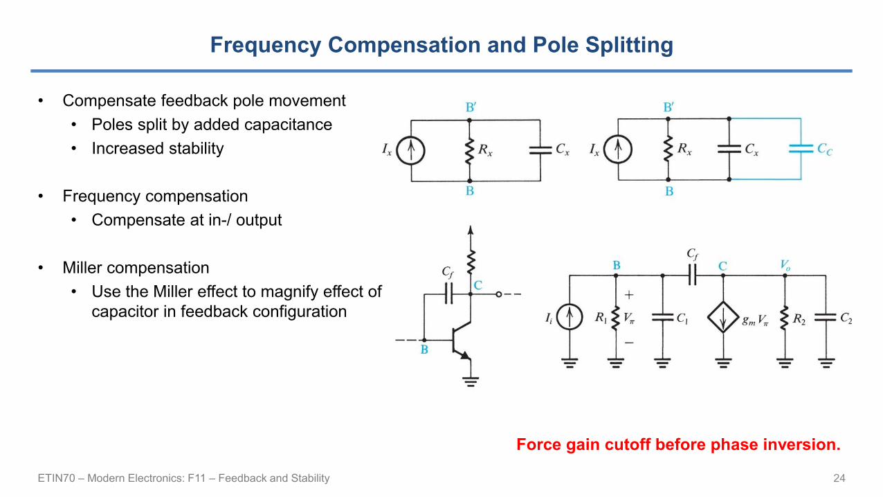
Frequency Compensation and Pole Splitting
• Compensate feedback pole movement
• Poles split by added capacitance
• Increased stability
• Frequency compensation
• Compensate at in-/ output
• Miller compensation
• Use the Miller effect to magnify effect of
capacitor in feedback configuration
24
Force gain cutoff before phase inversion.