Embed Size (px)
Citation preview

8/8/2019 F150 Door Panel Removal
http://slidepdf.com/reader/full/f150-door-panel-removal 1/12
Signal ® Mirror Installation Instructions
T H E s a f et y a c ce ss o r y o f t h e 21s t C e n t u r y . ™
P/N 210-0096-0 Rev. A3 (9/3/08), BTV © 2004 Muth Mirror Systems,
Pre-wired with side signals Pre-wired without side signals
2004 – 2008 Ford F-150 XLT, FX4, & Lariat
Without side directional lights, see page 2 With side directional lights, see page 6
®

8/8/2019 F150 Door Panel Removal
http://slidepdf.com/reader/full/f150-door-panel-removal 2/12
INCLUDED ITEMS:
1 left and 1 right Signal® mirror 1 left and 1 right wire harness2 wire taps
2 ring connectors
1 instruction manual
REQUIRED TOOLS:
Ratchet with extension or ratcheting screwdriverT-27 Torx
4mm socket6mm socket
8mm socket10mm socket
11mm socket
7/32” socketSocket wrench
Large slotted screwdriver
Small pry barGopher wire
Electrical tape
Wire crimper and stripper
Needle nose pliersMultimeter or wire tester
Sturdy gloves
Safety glasses or goggles
PROBLEMS OR QUESTIONS?
Technical Assistance is available by calling
Muth Mirror Systems Technicians at:
1-800-844-6616
Monday through Friday
Between 8:00 a.m. and 5:00 p.m. CST
Or through the Muth web site:
www.muthco.com
Or via E-mail: [email protected]
Please read instructions prior to installation.
Note: Professional Installation RecommendedWarranty does not cover damage to the vehicle or mirror housing due to improper installation. The following
installation instructions are to be considered as a guide only. Door removal procedures, indicator wire colorand location may have changed since publication of these instructions. The installer is responsible for any
damage that may occur during installation.
Downloadable installation instructions are
available via the internet at:www.muthco.com

8/8/2019 F150 Door Panel Removal
http://slidepdf.com/reader/full/f150-door-panel-removal 3/12
1. Open driver’s side door and lower the window.
2. Insert a small flathead screwdriver into small slot. Press down and pull out plastic cover above door handle (A). Using an 8mm socket, unscrew the (2)
bolts revealed by the removal of the plastic cover (B&C).
3. Use a small pry bar, pop open the control console. Disconnect all wiring connections behind control console and remove control console. Remove (2) bolts revealed by the
removal of the control console using a 10mm socket.
4. Using a small pry bar, remove speaker cover (4a). Remove (4) screws with 7/32” socket (4b). Unplug and remove speaker. Remove plastic shield. Pop out the (4) plastic
inserts with a small pry bar (4c).5. Remove (2) screws located on the bottom of the door panel.
2 3
4a 4b 4c
Door Panel Removal
(4)
B
A
C
Remove
4
3
2
8/8/2019 F150 Door Panel Removal
http://slidepdf.com/reader/full/f150-door-panel-removal 4/12
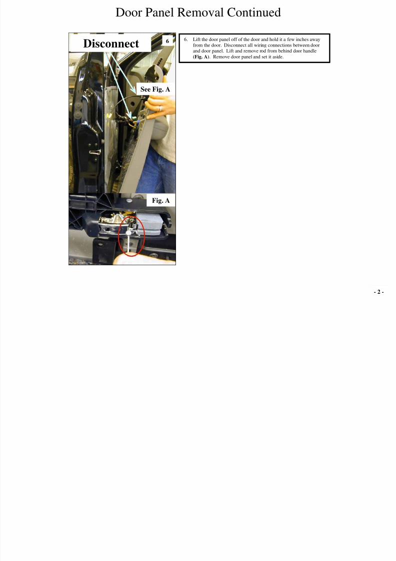
6. Lift the door panel off of the door and hold it a few inches away
from the door. Disconnect all wiring connections between door
and door panel. Lift and remove rod from behind door handle
(Fig. A). Remove door panel and set it aside.
6
Door Panel Removal Continued
See Fig. A
Disconnect
Fig. A
- 2 -

8/8/2019 F150 Door Panel Removal
http://slidepdf.com/reader/full/f150-door-panel-removal 5/12
7. Remove plastic cover. Using an 11mm socket, remove the (4) nuts holding
the mirror housing to the door.
8. Disconnect the wiring connector. CAUTION: Before going on to the
next step, you must hold onto mirror housing. Not doing so, could
result in mirror housing falling to the ground and breaking. Remove
the top post that holds the mirror housing to the door frame using a 4mmsocket. Jiggle and remove mirror housing from door frame.
7 8
Housing Removal
Disconnect
Remove Post
Remove Nuts
Hold mirror housing

8/8/2019 F150 Door Panel Removal
http://slidepdf.com/reader/full/f150-door-panel-removal 6/12
WARNING! Safety glasses and sturdy
gloves are recommended for mirror glass
replacement.
9. Place mirror housing on a cloth covered, flat
surface. Re-insert top post back into housing sail.
10. Remove foam cover.
11. Push in the inboard side of the mirror to pivot the
outboard edge outward. Insert a large flat head
screwdriver in between motor actuator and mirror
backplate. Slowly twist and pry backplate away
from motor actuator. Repeat process around motoractuator until backplate dislodges.
12. If heated, disconnect the heater terminals from the
back of the OE glass. Remove OE glass from
mirror housing.
13. Using a T-27 Torx, remove (4) screws holding the
mirror housing cover in place.
14. Remove mirror housing cover.
Glass Replacement
10 11
12
9
13 14
Remove screwsDisconnect heater terminals
- 3 -

8/8/2019 F150 Door Panel Removal
http://slidepdf.com/reader/full/f150-door-panel-removal 7/12
15. Using the shorter of the two supplied wire harnesses, route the open end alongside OE wires as
shown.
16. Keep routing the supplied wire harness by following OE wires on the housing sail.
17. Connect the Signal® mirror wires to the Signal® mirror wire harness (A). If heated, reconnect
the heater wires to the heater terminals on the back of the new Signal® mirror (B). NOTE: There
is no polarity so the wires may be interchanged. Disregard heater connections on vehicles not
equipped with outside heated mirrors. Carefully tuck wires behind motor actuator. Pull on the
Signal® mirror wire harness to ensure there is no slack within mirror housing. Replace mirror
housing cover with the (4) screws. Align the snap ring with the motor actuator and snap into
place. Press down on all sides to ensure proper engagement of the snap ring to the motor actuator.
18. Insert the Signal® mirror wire harness through the hole in the foam insulation. Replace foaminsulation onto mirror housing sail.
15 16
18
Glass Replacement Continued
17
Signal ® Mirror
Wire Harness
Signal ® Mirror
Wire Harness
B
ASignal ® Mirror
Wire Harness

8/8/2019 F150 Door Panel Removal
http://slidepdf.com/reader/full/f150-door-panel-removal 8/12
19. Route Signal® mirror wire harness through mirror mount hole and mount mirror
housing to the door frame by securing all (4) posts. Reconnect the OE mating
connector.
20. Pull and lift-up floor board trim.
21. Remove kick panel cover as shown above.
22. Remove kick panel.
1920 20
19. Route Signal® mirror wire harness through mirror mount hole. Secure (3) of the (4)
posts on the housing sail to the door frame. Note: The 4th
post will be used later to
mount the grounding ring to it. Reconnect the OE mating connector. Strip the
routed Signal® mirror wire harness to about 4” – 6”. Cut and split the (2) bonded
wires as shown above.
***Repeat steps for passenger side Signal ® mirror***
20a. DRIVER SIDE: Carefully strip back OE wire sheathing as needed. Find the
GREEN WITH WHITE STRIPE wire. Turn the ignition key so that electrical
power is on and activate the driver side turn indicator. Probe the GREEN WITH
WHITE STRIPE wire with the wire tester to verify that flashing turn indicator
power is present. Label that wire as ‘driver side turn’.
20b. PASSENGER SIDE: Carefully strip back OE wire sheathing as needed. Find the
WHITE WITH BLUE STRIPE wire. Turn the ignition key so that electrical power
is on and activate the passenger side turn indicator. Probe the WHITE WITH
BLUE STRIPE wire with the wire tester to verify that flashing turn indicator power
is present. Label that wire as ‘passenger side turn’.
Pre-wired VehicleNon Pre-wired Vehicle
19
Mirror Mounting/Wire RoutingMirror Mounting/Wire Routing
21 22
Secure (3) of the
(4) posts in place
Trim/split wires
- 4 -
IF WIRES ARE NOT LOCATED IN DOORS, USE NON PRE-WIRED INSTRUCTIONS

8/8/2019 F150 Door Panel Removal
http://slidepdf.com/reader/full/f150-door-panel-removal 9/12
et
23. Remove both ends of the rubber from the door
frame and vehicle. Route the Signal® mirror
wire harness down inside door frame and out
the hole vacated by the removal of the rubber
boot. Caution: Make sure Signal ® mirror
wire harness does not go inside of window
track. Continue routing the Signal® mirror
wire harness through the rubber boot and into
the vehicle. Gently pull on the Signal®
mirror wire harness to eliminate any slack
during routing.
24. Cut and split the bonded wires. Route the
black wire from Signal® mirror wire harness
to a grounding location. Cut and strip the
black wire. Crimp it to a supplied grounding
ring. Attach the grounding ring to a suitable
grounding source as shown.
***Repeat steps for passenger sideSignal ® mirror***
23 21
DRIVER SIDE SIGNAL® MIRROR
21a. Route the black wire from Signal® mirror wire harness to the unsecured bolt. Cut
and strip the black wire, and crimp it to a supplied grounding ring. Attach the
grounding ring to the 4th post and secure it with its nut. Splice the red wire from the
Signal® mirror wire harness to the wire labeled ‘driver side turn’.
PASSENGER SIDE SIGNAL® MIRROR
21b. Route the black wire from Signal® mirror wire harness to the unsecured bolt. Cut
and strip the black wire, and crimp it to a supplied grounding ring. Attach the
grounding ring to the 4th
bolt and secure it with its nut. Splice the red wire from the
Signal® mirror wire harness to the wire labeled ‘passenger side turn’.
22. Replace the plastic door frame moldings and trim, door panels, and all accessories.
***For splicing procedures, go to step 26***
Pre-wired VehicleNon Pre-wired Vehicle
24
Wire Routing ContinuedWire Routing Continued

8/8/2019 F150 Door Panel Removal
http://slidepdf.com/reader/full/f150-door-panel-removal 10/12
25. The vehicle’s electrical wiring is located in a wire bundle under the dash. Route both red wires from the Signal® mirror wireharnesses to this wiring location. Make sure there is enough slack in the wires for splicing. Locate the GREEN WITH WHITE
STRIPE wire. Turn the ignition key so that electrical power is on and activate the driver side turn indicator. Probe the GREEN
WITH WHITE STRIPE wire with the wire tester to verify that flashing turn indicator power is present. Label that wire as ‘driverside turn’. Locate the WHITE WITH BLUE STRIPE wire. Activate the passenger side turn indicator and probe the WHITE WITH
BLUE STRIPE wire with the wire tester to verify that flashing turn indicator power is present. Label that wire as ‘passenger side
turn’.
Non Pre-wired Vehicle OnlyWire Routing Continued
25
- 5 -

8/8/2019 F150 Door Panel Removal
http://slidepdf.com/reader/full/f150-door-panel-removal 11/12
USE THE INCLUDED WIRE TAPS AND FOLLOW THE FOUR STEPS ABOVE TO SPLICE INTO THE TURN INDICATOR WIRES
A. Splice the RED wire from the driver side harness into the GREEN WITH WHITE STRIPE wire previously labeled ‘driver side turn’.
B. Splice the RED wire from the passenger side harness into the WHITE WITH BLUE STRIPE wire previously labeled ‘passenger side turn’.C. Strip and twist together the ends of the black wires from each harness. Crimp them together in the supplied ring connector and ground to a
suitable nearby location on the metal framework of the vehicle.
D. Activate each turn indicator to verify that the Signal® mirrors are working.
E. Replace the plastic door frame moldings and trim, door panels, and all accessories.
1 32 4
Muth products are protected by these, and other pending, United States Patents3,075,779 5,005,009 5,014,167 5,128,659 5,207,492 5,355,284 5,361,190 5,481,409 5,528,422 5,619,374 5,619,375
5,788,357 6,005,724 6,045,243 6,076,948 6,257,746 6,700,123 6,749,325 6,918,685 7,008,091 7,015,642 7,104,676 D363,920D394,833 D409,540 D425,466 D426,506 D426,507 D427,128 D428,372 D428,373 D428,842 D429,202 D430,088

8/8/2019 F150 Door Panel Removal
http://slidepdf.com/reader/full/f150-door-panel-removal 12/12
- 6 -
WARNING! Safety glasses
and sturdy gloves are
recommended for mirror
glass replacement.
Vehicle with Side Directional Lights
1
7
54
32
**For ease of access, you may need to pivot mirror housing back and forth**
2. Push in the inboard side of the mirror to pivot the outboard edge outward. Insert a
large flat head screwdriver in between motor actuator and mirror backplate.
Slowly twist and pry backplate away from motor actuator. Repeat process around
motor actuator until backplate dislodges. If heated, disconnect heater connectorsand remove OE mirror backplate.
3. Use a T-27 Torx, remove the (4) screws.
4. Remove mirror housing cover.
5. Using one of the supplied Signal® mirror wire harness, insert (from the front) the
open end (the end without connector) behind motor actuator (A) and out the center
hole (B). Locate the black wire and the green w/ white stripe wire coming off of
the side indicator. Route the Signal® mirror wires to the OE indicator wires and
cut to length. Split the Signal® mirror wire harness up about 2 inches. Using (1)
of the supplied wire-tap connectors, splice together the red wire (on the Signal®
mirror wire harness) and the green w/ white stripe wire (on the OE indicator wireharness). With another wire-tap connector, connect the black wire from the
Signal® mirror wire harness to the black wire from the OE indicator wire harness
(C). Replace mirror housing cover with the (4) screws.
6. Connect the two mating connectors between the Signal® mirror and the Signal®
mirror wire harness (A). If heated, connect the heater terminals to the OE heater
wires (B). NOTE: There is no polarity so the wires may be interchanged.
Carefully tuck wires behind motor actuator. Align the snap ring with the motor
actuator and snap into place. Press down on all sides to ensure proper engagement
of the snap ring to the motor actuator.7. Insert key in the ignition and activate turn indicator to verify that the Signal
®
mirror is working properly. Repeat step 2 - 7 for the installation of the other side
Signal® mirror.
If your vehicle comes equipped with side directional lights (as shown), use the following steps to complete your installation of our Signal ® mirror.
REMOVE SCREWS
A
A
B
C
B
6