Embed Size (px)
Citation preview
FA-103 and FA-106Fire Alarm Control Panels
LT-1200 Rev 0 February 2017Installation and Operation Manual
Advanced Life Safety Solutions

FA-106 Fire Alarm Control Panel
i
Table of Contents
Introduction ............................................................................................................................. 1Mechanical Installation ........................................................................................................... 1
Conduits for Wiring............................................................................................................... 4Clearances ........................................................................................................................... 4
DIP SWITCH SELECTION........................................................................................................ 5Wiring ....................................................................................................................................... 6
Detection (IDC) Zones ......................................................................................................... 6Signal (NAC) Zones ............................................................................................................. 6Alarm and Trouble Relays.................................................................................................... 6Remote Annunciation........................................................................................................... 6A.C. Power and Batteries..................................................................................................... 6
Wiring Tables and Information............................................................................................... 9Trouble Indicators and Controls............................................................................................ 11
Common Trouble LED ......................................................................................................... 11Buzzer/Buzzer Silence Pushbutton...................................................................................... 11Detection Zone Trouble LED................................................................................................ 11Ground Fault LED ................................................................................................................ 11Battery Fault LED................................................................................................................. 11Detection Zone Disable........................................................................................................ 11
Sequence of Operation ........................................................................................................... 12Normal.................................................................................................................................. 12Alarm.................................................................................................................................... 12Signal silence (SIG SIL) ....................................................................................................... 12Reset.................................................................................................................................... 12Lamp Test ............................................................................................................................ 12
System Checkout .................................................................................................................... 12Power up and Troubleshooting ............................................................................................. 12Appendix A: Electrical Specifications................................................................................... 13Appendix B: Compatible Devices .......................................................................................... 14
FA-106 and FA-103 Underwriters Laboratories Canada ULC Listed 2-Wire Smoke Detectors ................................................................................... 14
Appendix C: Battery Calculations (Selection Guide)........................................................... 16Master Warranty and Warning Information........................................................................... 17
ii
List of Figures
Figure 1: Backbox and flush trim mounting details ................................................................. 2Figure 2: Assembly of FA-106 and FA-103 Fire Alarm Panels ............................................... 3Figure 3: Conduits for Wiring .................................................................................................. 4Figure 4: Setting the DIP Switch functions ............................................................................. 5Figure 5: A.C. Power and Battery Connection........................................................................ 6Figure 6: Circuit Board Layout ................................................................................................ 7Figure 7: Detection and signal wiring...................................................................................... 8Figure 8: Alarm and trouble relay contacts, remote annunciation and
four-wire detector wiring instructions ....................................................................... 10Figure 9: Front Panel Display ................................................................................................. 11
FA-106 Installation and Operation Manual
1
Introduction
The FA-106 is a supervised six-zone 24VDC Fire Alarm Control Panel. The FA-103 is a supervised three-zone 24VDC Fire Alarm Control Panel. The panels are ULC listed and meet all performance and operational requirements of ULC. The FA-106 provides the following features:
• Six Class B (Style B) detection (IDC) zones
• Two Class B (Style Y) signal zones (NACs), 1.25A max per zone, 2A max total
• DIP switch selectable NAC outputs such as Temporal or Steady
• Alarm and trouble relay contacts
• Remote trouble buzzer and indication with the use of an RTI-1 Remote Indicator
• Individual zone silence/disable switch
• Buzzer silence button
• Subsequent alarm operation
• LED indicators for zone alarm and trouble, A.C. Power On, Common Trouble, Ground Fault, Battery Fault, CPU Fault, Signal Silenced and Common Alarm.
The FA-103 has the same features as above except there are only three detections zones. The enclosures and boards are identical except the FA-103 is depopulated and has terminal connections for three detection zones only. Use of the reference “the panel” will apply to both models FA-106 and FA-103.
Models available are:
Mechanical Installation
The panel can be surface or flush mounted. Refer to Figure 1 on page 2 for dimensions.
Surface Mounting1. Mark the location of the four mounting holes.
2. Install the top two screws into the wall and place the panel over the screws.
3. Install the bottom screws and tighten down all four screws.
Flush Mounting1. Make the wall cut-out according to the panel dimensions.
2. Remove the control panel door.
3. Mount the flush mounting trim (model FA-102TR) to the back box using the screws and nuts provided with the flush mounting kit.
4. Re-install the door on top of the flush trim. The cam lock may require a minor adjustment in order to compensate for the flush trim.
FA-103 Three detection zones, two NACs FACP with white door and black backbox.
FA-103R Three detection zones, two NACs FACP with red door and black backbox.
FA-106 Six detection zones, two NACs FACP with white door and black backbox.
FA-106R Six detection zones, two NACs FACP with red door and black backbox.
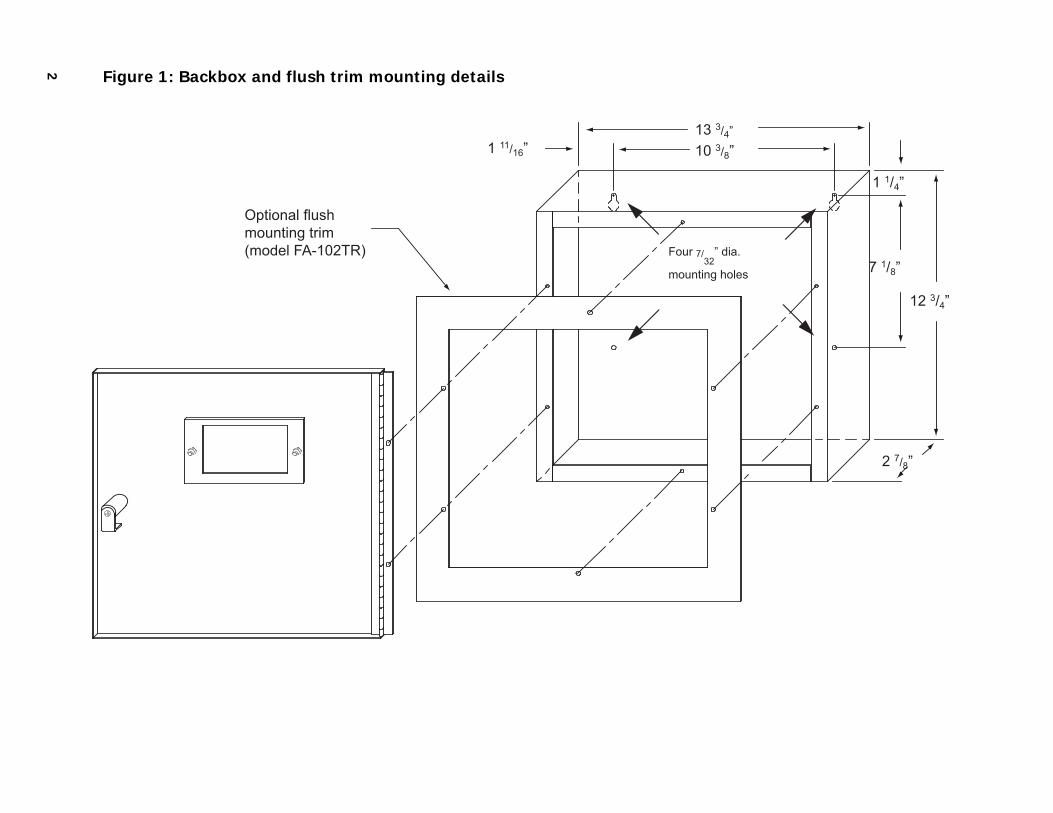
2 Figure 1: Backbox and flush trim mounting details
13 3/4”
12 3/4”
1 11/16”
Optional flush mounting trim (model FA-102TR) Four 7/
32” dia.
mounting holes
2 7/8”
7 1/8”
1 1/4”
10 3/8”
3
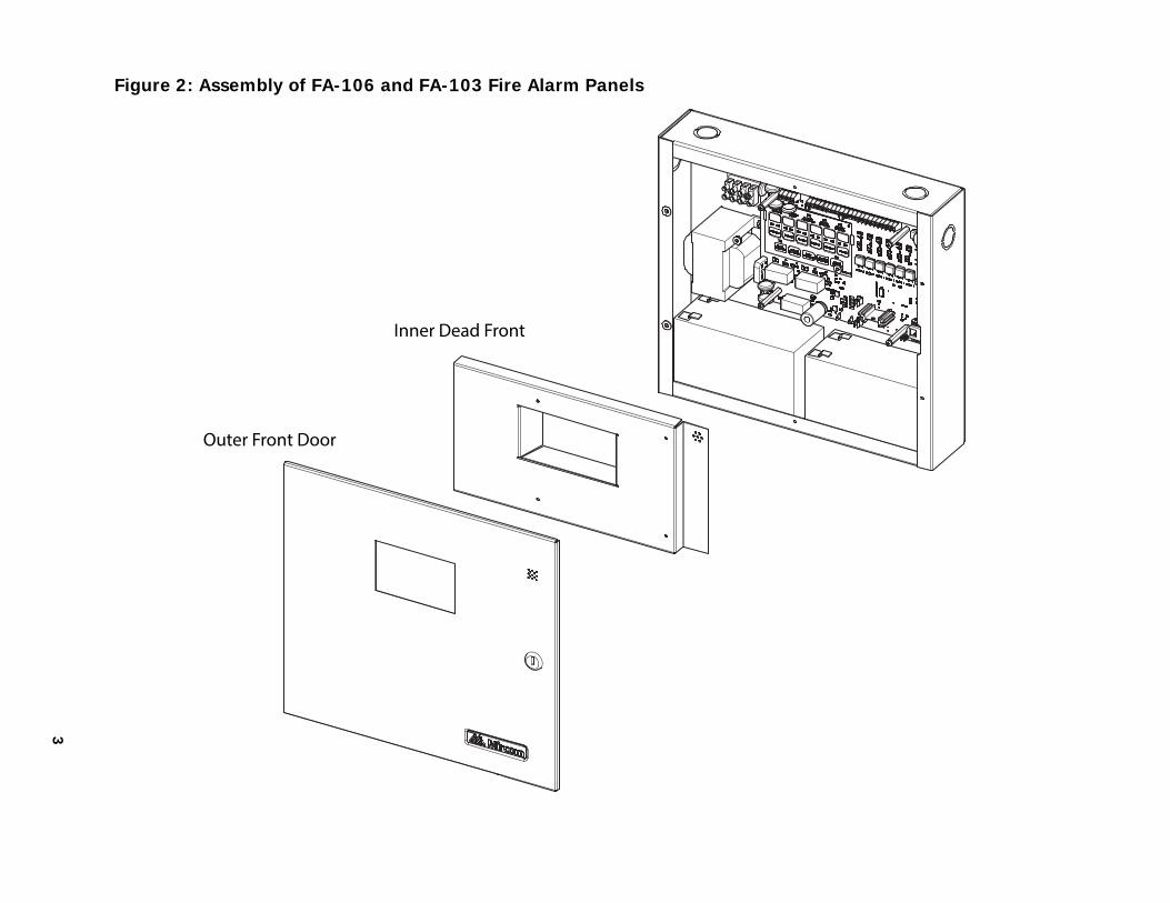
Figure 2: Assembly of FA-106 and FA-103 Fire Alarm Panels
Inner Dead Front
Outer Front Door
Mechanical Installation
4
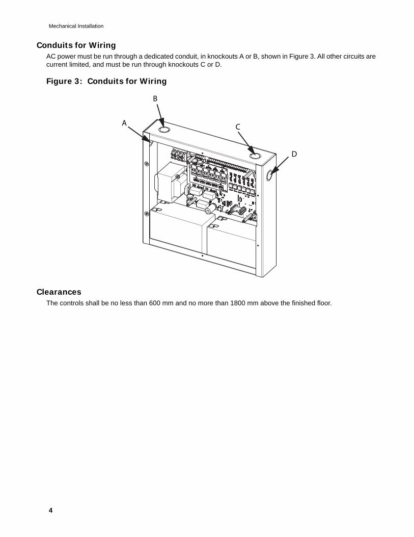
Conduits for WiringAC power must be run through a dedicated conduit, in knockouts A or B, shown in Figure 3. All other circuits are current limited, and must be run through knockouts C or D.
Figure 3: Conduits for Wiring
ClearancesThe controls shall be no less than 600 mm and no more than 1800 mm above the finished floor.
A
B
C
D
FA-106 Installation and Operation Manual
5
DIP SWITCH SELECTION
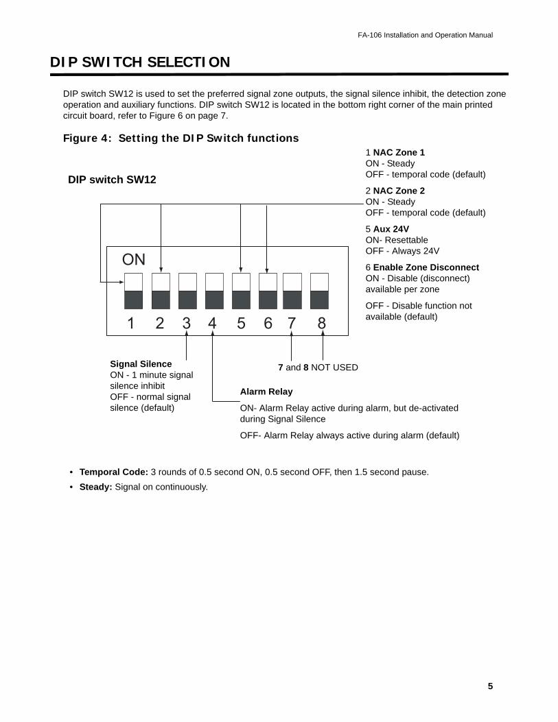
DIP switch SW12 is used to set the preferred signal zone outputs, the signal silence inhibit, the detection zone operation and auxiliary functions. DIP switch SW12 is located in the bottom right corner of the main printed circuit board, refer to Figure 6 on page 7.
Figure 4: Setting the DIP Switch functions
• Temporal Code: 3 rounds of 0.5 second ON, 0.5 second OFF, then 1.5 second pause.
• Steady: Signal on continuously.
1 2 3 4 5 6 7 8
ON
Alarm Relay
ON- Alarm Relay active during alarm, but de-activated during Signal Silence
OFF- Alarm Relay always active during alarm (default)
Signal Silence ON - 1 minute signal silence inhibitOFF - normal signal silence (default)
DIP switch SW12
1 NAC Zone 1 ON - Steady OFF - temporal code (default)
2 NAC Zone 2 ON - Steady OFF - temporal code (default)
5 Aux 24V ON- Resettable OFF - Always 24V
6 Enable Zone Disconnect ON - Disable (disconnect) available per zone
OFF - Disable function not available (default)
7 and 8 NOT USED
6
Wiring
Detection (IDC) ZonesThe system has six detection zones (three for the FA-103). Refer to Figure 7 on page 8 for wiring instruction and to Table 1 on page 9 for wire size.
Signal (NAC) ZonesThere are two signal zones available for bells and horns providing 1.25A maximum per zone with 2A maximum total signal power. Refer to Figure 7 on page 8 for NAC circuit for wiring instruction and to Table 2 on page 9 for wire size.
Alarm and Trouble RelaysAlarm and trouble relay contacts are provided. Refer to Figure 8 on page 10 for contact location and designation.
Remote AnnunciationAnnunciation outputs are provided for connection to an RTI-1 Remote Trouble indicator. Refer to Figure 8 on page 10 for wiring instruction.
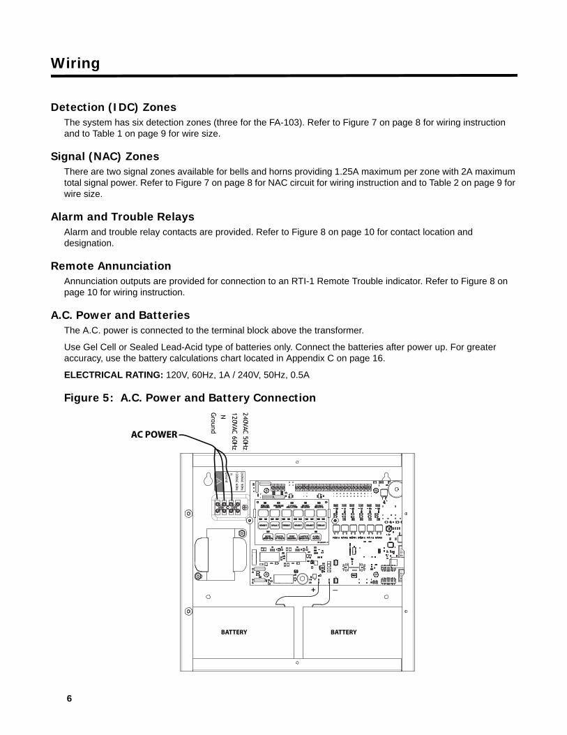
A.C. Power and BatteriesThe A.C. power is connected to the terminal block above the transformer.
Use Gel Cell or Sealed Lead-Acid type of batteries only. Connect the batteries after power up. For greater accuracy, use the battery calculations chart located in Appendix C on page 16.
ELECTRICAL RATING: 120V, 60Hz, 1A / 240V, 50Hz, 0.5A
Figure 5: A.C. Power and Battery Connection
240VAC 50Hz
120VAC 60Hz
NGround
240VAC 50Hz
120VAC 60Hz
NGround
+ _
AC POWER
BATTERY BATTERY
7
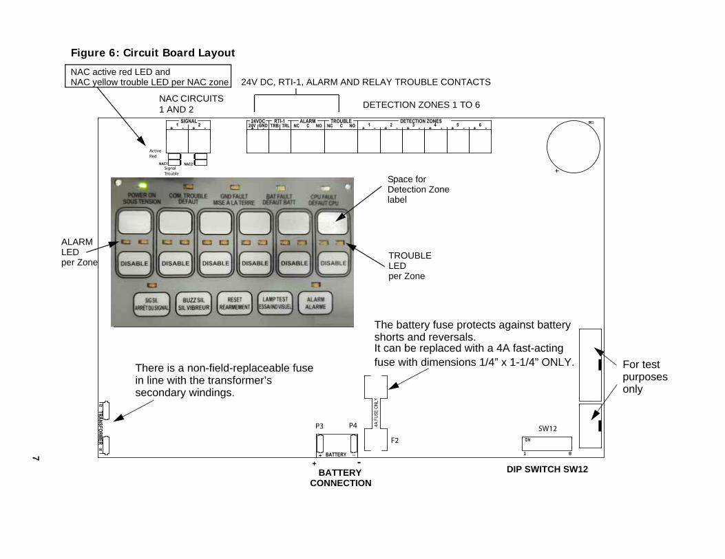
Figure 6: Circuit Board Layout
SW12
F2
P3 P4
Signal Trouble
Active Red
NAC CIRCUITS 1 AND 2
24V DC, RTI-1, ALARM AND RELAY TROUBLE CONTACTS
BATTERY
CONNECTION
+ -
For test purposesonly
DETECTION ZONES 1 TO 6
DIP SWITCH SW12
ALARMLEDper Zone
TROUBLELEDper Zone
Space forDetection Zonelabel
NAC active red LED andNAC yellow trouble LED per NAC zone
The battery fuse protects against battery
It can be replaced with a 4A fast-acting fuse with dimensions 1/4” x 1-1/4” ONLY.
shorts and reversals.
There is a non-field-replaceable fuse in line with the transformer’s secondary windings.
Wiring
8
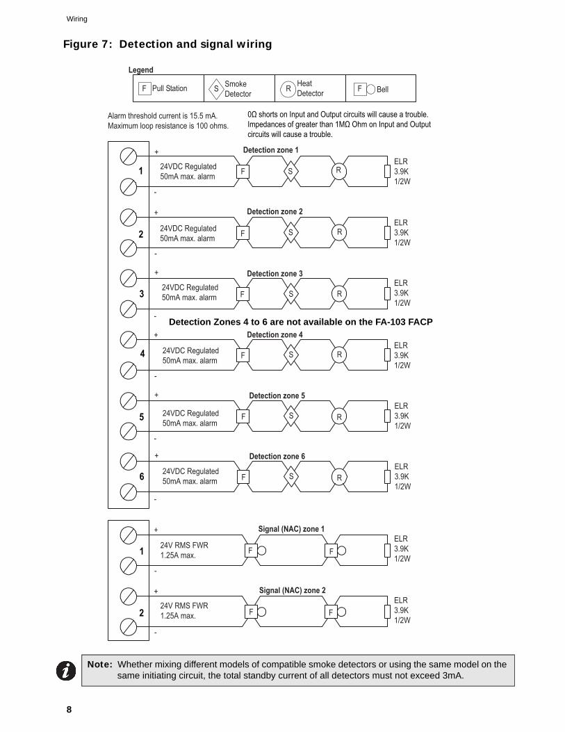
Figure 7: Detection and signal wiring
Note: Whether mixing different models of compatible smoke detectors or using the same model on the same initiating circuit, the total standby current of all detectors must not exceed 3mA.
Legend
Pull Station SmokeDetector
HeatDetector BellFF S R
Alarm threshold current is 15.5 mA.Maximum loop resistance is 100 ohms.
ELR3.9K1/2W
F S R
Detection zone 1
F F
ELR3.9K1/2W
Signal (NAC) zone 1
Detection zone 2
+
-
+
-
24VDC Regulated50mA max. alarm
24VDC Regulated50mA max. alarm
24VDC Regulated50mA max. alarm
24VDC Regulated50mA max. alarm
24VDC Regulated50mA max. alarm
24VDC Regulated50mA max. alarm
24V RMS FWR1.25A max.
F S RELR3.9K1/2W
+
-
+
-
+
-
+
-
Detection zone 3
F S R
ELR3.9K1/2W
Detection zone 4
F S R
ELR3.9K1/2W
Detection zone 5
F S R
+
-
ELR3.9K1/2W
Detection zone 6
F S R
ELR3.9K1/2W
ELR3.9K1/2W
Signal (NAC) zone 2
24V RMS FWR1.25A max.
+
-
F F
1
1
2
2
3
4
5
6
0Ω shorts on Input and Output circuits will cause a trouble.Impedances of greater than 1MΩ Ohm on Input and Output circuits will cause a trouble.
Detection Zones 4 to 6 are not available on the FA-103 FACP
FA-106 Installation and Operation Manual
9
Wiring Tables and Information
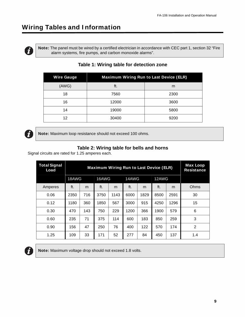
Table 1: Wiring table for detection zone
Table 2: Wiring table for bells and hornsSignal circuits are rated for 1.25 amperes each.
Note: The panel must be wired by a certified electrician in accordance with CEC part 1, section 32 “Fire alarm systems, fire pumps, and carbon monoxide alarms”.
Wire Gauge Maximum Wiring Run to Last Device (ELR)
(AWG) ft. m
18 7560 2300
16 12000 3600
14 19000 5800
12 30400 9200
Note: Maximum loop resistance should not exceed 100 ohms.
Total Signal Load Maximum Wiring Run to Last Device (ELR) Max Loop
Resistance
18AWG 16AWG 14AWG 12AWG 0hms
Amperes ft. m ft. m ft. m ft. m Ohms
0.06 2350 716 3750 1143 6000 1829 8500 2591 30
0.12 1180 360 1850 567 3000 915 4250 1296 15
0.30 470 143 750 229 1200 366 1900 579 6
0.60 235 71 375 114 600 183 850 259 3
0.90 156 47 250 76 400 122 570 174 2
1.25 109 33 171 52 277 84 450 137 1.4
Note: Maximum voltage drop should not exceed 1.8 volts.
Wiring Tables and Information
10
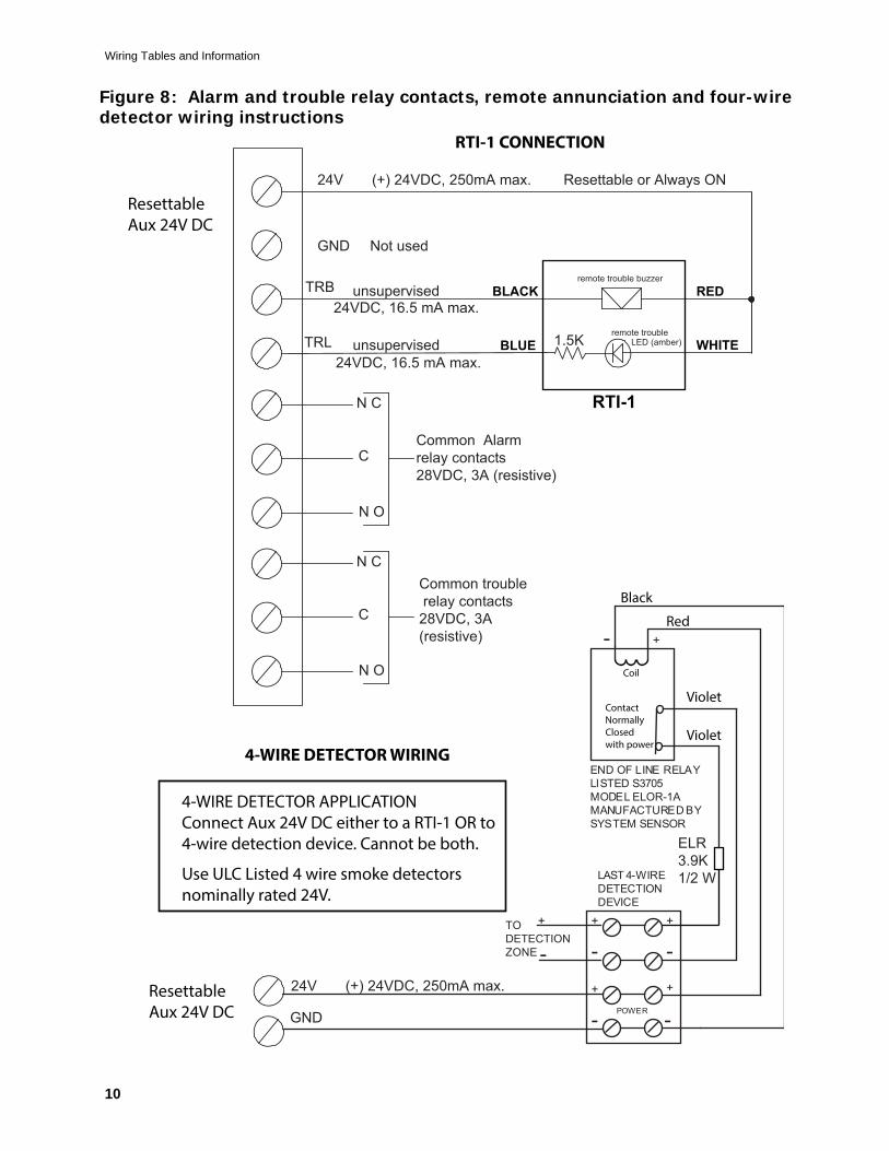
Figure 8: Alarm and trouble relay contacts, remote annunciation and four-wire detector wiring instructions
Common Alarmrelay contacts 28VDC, 3A (resistive)
Common trouble relay contacts 28VDC, 3A (resistive)
N C
C
N O
N C
C
N O
TRL
TRB24VDC, 16.5 mA max.
unsupervised
unsupervised24VDC, 16.5 mA max.
1.5K remote troubleLED (amber)
remote trouble buzzer
24V (+) 24VDC, 250mA max. Resettable or Always ON
24V (+) 24VDC, 250mA max.
GND Not used
GND
ELR3.9K1/2 W
RTI-1
BLACK
BLUE
RED
WHITE
ResettableAux 24V DC
ResettableAux 24V DC
+
-+
-TODETECTIONZONE
+
-+
- POWER
+
+
-
-
LAST 4-WIREDETECTIONDEVICE
END OF LINE RELAYLISTED S3705MODEL ELOR-1AMANUFACTURED BYSYSTEM SENSOR
4-WIRE DETECTOR APPLICATION Connect Aux 24V DC either to a RTI-1 OR to 4-wire detection device. Cannot be both.
RTI-1 CONNECTION
4-WIRE DETECTOR WIRING
Red
Black
Violet
VioletContactNormally Closedwith power
Coil
Use ULC Listed 4 wire smoke detectors nominally rated 24V.
FA-106 Installation and Operation Manual
11
Trouble Indicators and Controls
Common Trouble LEDThe yellow Common Trouble LED will flash and the buzzer will sound for any trouble in the panel.
Buzzer/Buzzer Silence PushbuttonThe buzzer will sound intermittently for any trouble. The buzzer will sound steadily for any alarm in the system. Pushing the Buzzer Silence button will silence the buzzer. Any subsequent alarm will resound the buzzer.
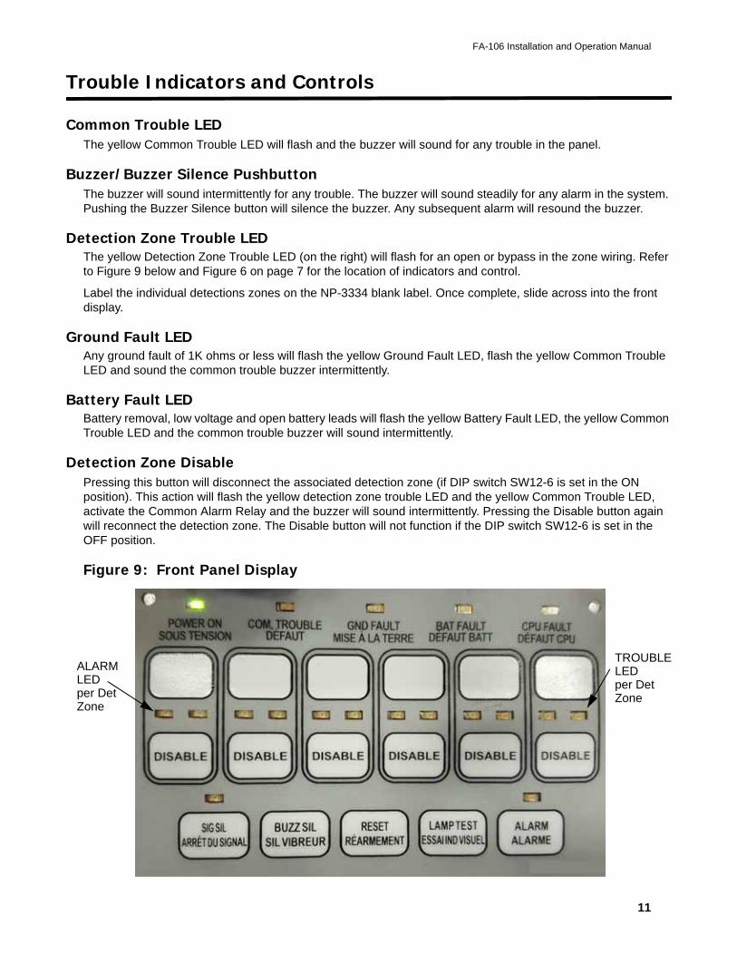
Detection Zone Trouble LEDThe yellow Detection Zone Trouble LED (on the right) will flash for an open or bypass in the zone wiring. Refer to Figure 9 below and Figure 6 on page 7 for the location of indicators and control.
Label the individual detections zones on the NP-3334 blank label. Once complete, slide across into the front display.
Ground Fault LEDAny ground fault of 1K ohms or less will flash the yellow Ground Fault LED, flash the yellow Common Trouble LED and sound the common trouble buzzer intermittently.
Battery Fault LEDBattery removal, low voltage and open battery leads will flash the yellow Battery Fault LED, the yellow Common Trouble LED and the common trouble buzzer will sound intermittently.
Detection Zone DisablePressing this button will disconnect the associated detection zone (if DIP switch SW12-6 is set in the ON position). This action will flash the yellow detection zone trouble LED and the yellow Common Trouble LED, activate the Common Alarm Relay and the buzzer will sound intermittently. Pressing the Disable button again will reconnect the detection zone. The Disable button will not function if the DIP switch SW12-6 is set in the OFF position.
Figure 9: Front Panel Display
ALARMLED
TROUBLELEDper DetZoneper Det
Zone
12
Sequence of Operation
Refer to Figure 6 on page 7 for the location of indicators and controls.
NormalAll indicators are normally OFF except for the green Power On LED. If there is an AC fail, the green Power On LED will flash, the yellow Common Trouble LED will flash and the buzzer will sound.
AlarmA red zone alarm LED will illuminate steadily for incoming alarm.
Signal silence (SIG SIL)If the 1 minute signal silence inhibit is selected, the signals cannot be silenced for 60 seconds after an alarm initiation. Once the 60 seconds have expired, pushing the signal silence button will silence all the bells and horns. Once the signals has been silenced, the yellow signal silenced LED will flash and the yellow common trouble LED will flash.
ResetPushing the reset button will restore all latched functions in the panel. The Reset button will not function during the 1 minute signal silence inhibit time (if selected via DIP switch SW12-3). The Reset button will not affect the disabled zones (if used).
Lamp TestPress this button and hold to illuminate all the LEDs. NOTE: The CPU FAIL LED will not illuminate during Lamp Test.
System Checkout
Before turning the power on,
1. Check all external wiring for opens, shorts or grounds.
2. Check that transformer cables are securely connected.
3. Check the A.C. power wiring for proper connection. To prevent sparking, do not connect batteries.
4. Check all DIP switches are set as required.
Power up and Troubleshooting
1. After completing all of the system checkout procedures, power up the panel. The Power On LED should illuminate.The trouble buzzer should sound intermittently, and the Common Trouble LED should flash, indi-cating battery fault.
2. Connect the batteries carefully, observing the correct polarity. The Common Trouble LED should extinguish. If the Common Trouble LED stays on, check the front panel for illumination of the following LEDs:• Battery LED indicates that the battery voltage may be too low (below 20.4V).• Ground Fault LED indicates a ground on one or more of the extended wires.• Zone Trouble LED indicates an open loop on the detection zone specified.
• Common Trouble LED alone indicates a possible open loop or short in the signal zone. To determine which NAC zone, you may view which NAC 1 or 2 yellow trouble LEDs is flashing (the main board top left LEDs), see Figure 6 on page 7.
FA-106 Installation and Operation Manual
13
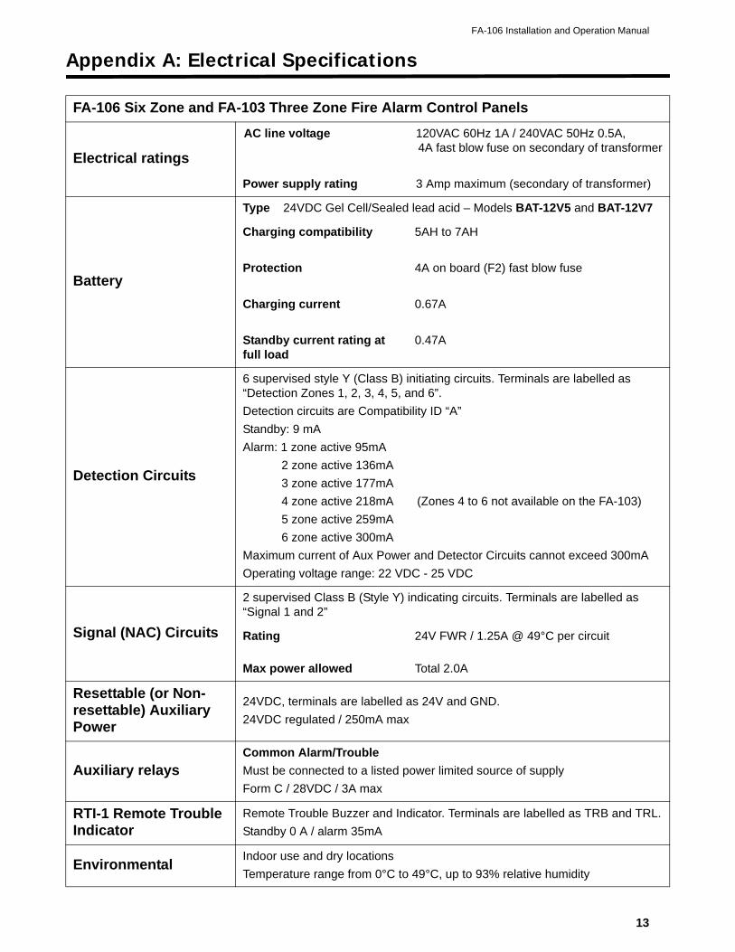
Appendix A: Electrical Specifications
FA-106 Six Zone and FA-103 Three Zone Fire Alarm Control Panels
Electrical ratings
AC line voltage
Power supply rating
120VAC 60Hz 1A / 240VAC 50Hz 0.5A, 4A fast blow fuse on secondary of transformer
3 Amp maximum (secondary of transformer)
Battery
Type 24VDC Gel Cell/Sealed lead acid – Models BAT-12V5 and BAT-12V7
Charging compatibility
Protection
Charging current
Standby current rating at full load
5AH to 7AH
4A on board (F2) fast blow fuse
0.67A
0.47A
Detection Circuits
6 supervised style Y (Class B) initiating circuits. Terminals are labelled as “Detection Zones 1, 2, 3, 4, 5, and 6”.
Detection circuits are Compatibility ID “A”
Standby: 9 mA
Alarm: 1 zone active 95mA
2 zone active 136mA
3 zone active 177mA
4 zone active 218mA (Zones 4 to 6 not available on the FA-103)
5 zone active 259mA
6 zone active 300mA
Maximum current of Aux Power and Detector Circuits cannot exceed 300mA
Operating voltage range: 22 VDC - 25 VDC
Signal (NAC) Circuits
2 supervised Class B (Style Y) indicating circuits. Terminals are labelled as “Signal 1 and 2”
Rating
Max power allowed
24V FWR / 1.25A @ 49°C per circuit
Total 2.0A
Resettable (or Non-resettable) Auxiliary Power
24VDC, terminals are labelled as 24V and GND.
24VDC regulated / 250mA max
Auxiliary relaysCommon Alarm/Trouble
Must be connected to a listed power limited source of supply
Form C / 28VDC / 3A max
RTI-1 Remote Trouble Indicator
Remote Trouble Buzzer and Indicator. Terminals are labelled as TRB and TRL.
Standby 0 A / alarm 35mA
EnvironmentalIndoor use and dry locations
Temperature range from 0°C to 49°C, up to 93% relative humidity
14
Appendix B: Compatible Devices
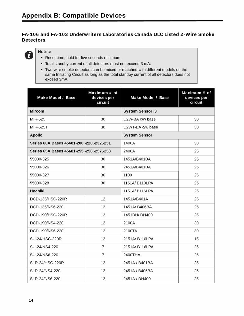
FA-106 and FA-103 Underwriters Laboratories Canada ULC Listed 2-Wire Smoke Detectors
Notes:• Reset time, hold for five seconds minimum.
• Total standby current of all detectors must not exceed 3 mA.
• Two-wire smoke detectors can be mixed or matched with different models on the same Initiating Circuit as long as the total standby current of all detectors does not exceed 3mA.
Make Model / BaseMaximum # of
devices per circuit
Make Model / BaseMaximum # of
devices per circuit
Mircom System Sensor i3
MIR-525 30 C2W-BA c/w base 30
MIR-525T 30 C2WT-BA c/w base 30
Apollo System Sensor
Series 60A Bases 45681-200,-220,-232,-251 1400A 30
Series 65A Bases 45681-255,-256,-257,-258 2400A 25
55000-325 30 1451A/B401BA 25
55000-326 30 2451A/B401BA 25
55000-327 30 1100 25
55000-328 30 1151A/ B110LPA 25
Hochiki 1151A/ B116LPA 25
DCD-135/HSC-220R 12 1451A/B401A 25
DCD-135/NS6-220 12 1451A/ B406BA 25
DCD-190/HSC-220R 12 1451DH/ DH400 25
DCD-190/NS4-220 12 2100A 30
DCD-190/NS6-220 12 2100TA 30
SU-24/HSC-220R 12 2151A/ B110LPA 15
SU-24/NS4-220 7 2151A/ B116LPA 25
SU-24/NS6-220 7 2400THA 25
SLR-24/HSC-220R 12 2451A / B401BA 25
SLR-24/NS4-220 12 2451A / B406BA 25
SLR-24/NS6-220 12 2451A / DH400 25
FA-106 Installation and Operation Manual
15
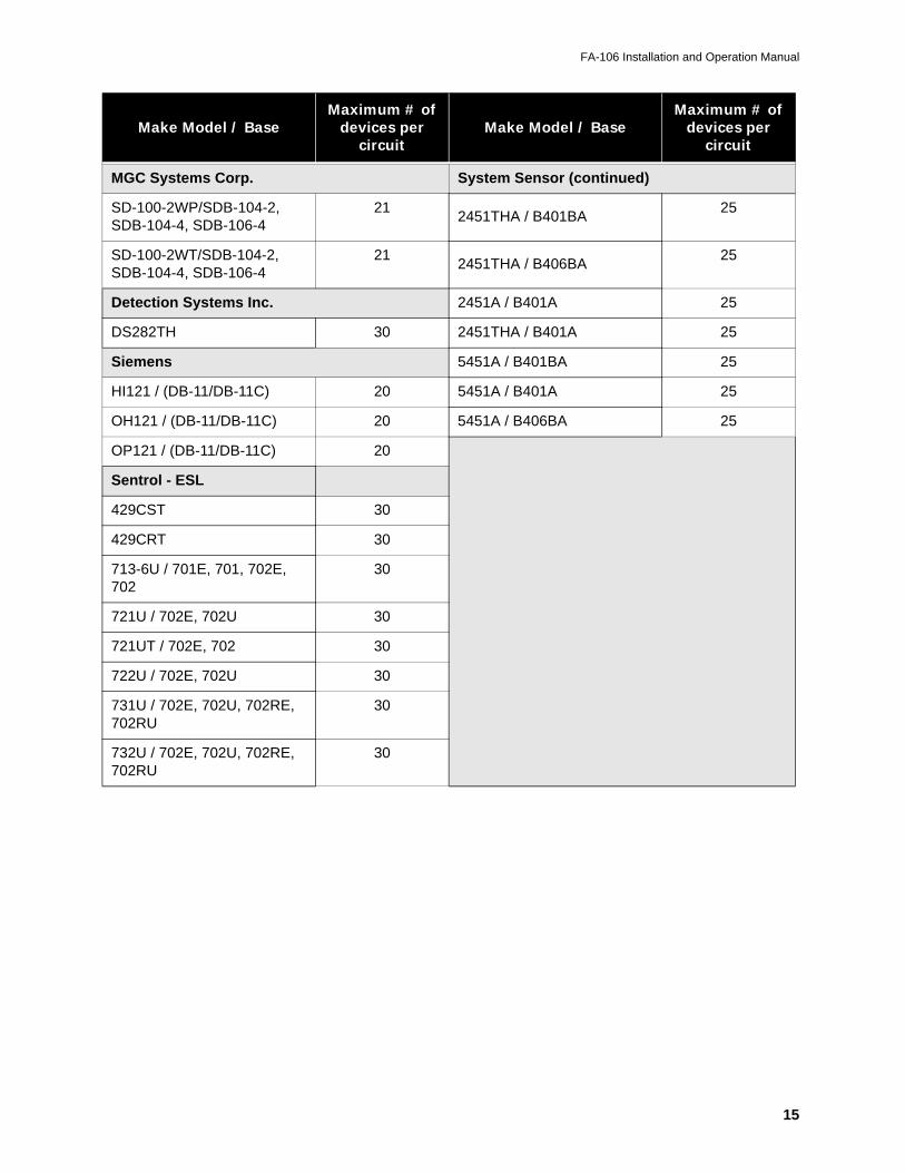
MGC Systems Corp. System Sensor (continued)
SD-100-2WP/SDB-104-2, SDB-104-4, SDB-106-4
212451THA / B401BA
25
SD-100-2WT/SDB-104-2, SDB-104-4, SDB-106-4
212451THA / B406BA
25
Detection Systems Inc. 2451A / B401A 25
DS282TH 30 2451THA / B401A 25
Siemens 5451A / B401BA 25
HI121 / (DB-11/DB-11C) 20 5451A / B401A 25
OH121 / (DB-11/DB-11C) 20 5451A / B406BA 25
OP121 / (DB-11/DB-11C) 20
Sentrol - ESL
429CST 30
429CRT 30
713-6U / 701E, 701, 702E, 702
30
721U / 702E, 702U 30
721UT / 702E, 702 30
722U / 702E, 702U 30
731U / 702E, 702U, 702RE, 702RU
30
732U / 702E, 702U, 702RE, 702RU
30
Make Model / BaseMaximum # of
devices per circuit
Make Model / BaseMaximum # of
devices per circuit
16
Appendix C: Battery Calculations (Selection Guide)
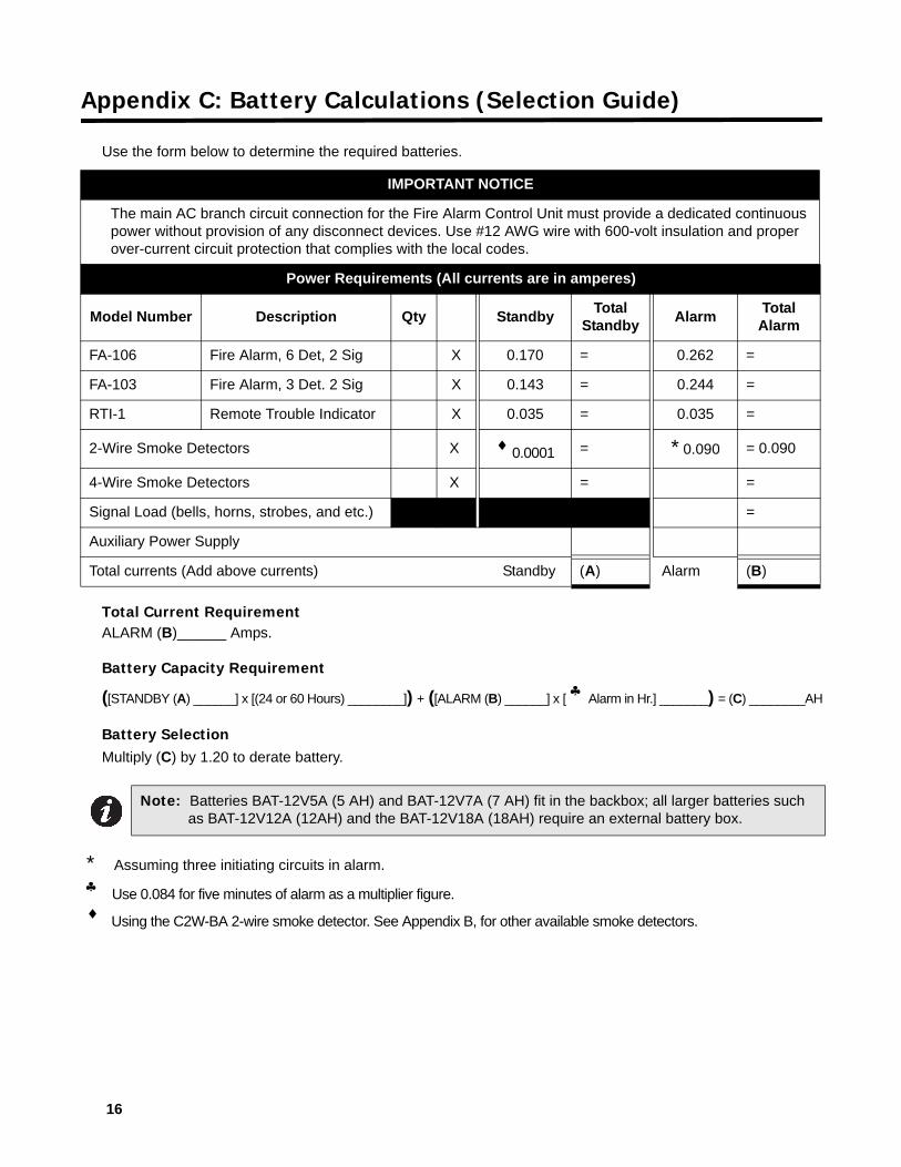
Use the form below to determine the required batteries.
Total Current RequirementALARM (B)______ Amps.
Battery Capacity Requirement
([STANDBY (A) ______] x [(24 or 60 Hours) ________]) + ([ALARM (B) ______] x [ ♣ Alarm in Hr.] _______) = (C) ________AH
Battery SelectionMultiply (C) by 1.20 to derate battery.
* Assuming three initiating circuits in alarm.
♣ Use 0.084 for five minutes of alarm as a multiplier figure.
♦
Using the C2W-BA 2-wire smoke detector. See Appendix B, for other available smoke detectors.
IMPORTANT NOTICE
The main AC branch circuit connection for the Fire Alarm Control Unit must provide a dedicated continuous power without provision of any disconnect devices. Use #12 AWG wire with 600-volt insulation and proper over-current circuit protection that complies with the local codes.
Power Requirements (All currents are in amperes)
Model Number Description Qty Standby Total
Standby Alarm
Total Alarm
FA-106 Fire Alarm, 6 Det, 2 Sig X 0.170 = 0.262 =
FA-103 Fire Alarm, 3 Det. 2 Sig X 0.143 = 0.244 =
RTI-1 Remote Trouble Indicator X 0.035 = 0.035 =
2-Wire Smoke Detectors X ♦ 0.0001 = * 0.090 = 0.090
4-Wire Smoke Detectors X = =
Signal Load (bells, horns, strobes, and etc.) =
Auxiliary Power Supply
Total currents (Add above currents) Standby (A) Alarm (B)
Note: Batteries BAT-12V5A (5 AH) and BAT-12V7A (7 AH) fit in the backbox; all larger batteries such as BAT-12V12A (12AH) and the BAT-12V18A (18AH) require an external battery box.
FA-106 Installation and Operation Manual
17
Master Warranty and Warning Information
Terms & InterpretationIn this document the term MGC System refers to all fire alarm, nurse call, and building automation products manufactured by Mircom Group of Companies, Mircom Technologies Ltd., MGC Systems Corp or subsidiaries and affiliates and includes specific systems such as MiCare™, OpenBAS™, and FlexNet™. Moreover, the term MGC System extends to cover all component parts and software used within such products.
Warning Please Read CarefullyAll MGC Systems are subject to terms and conditions of sale as follows:
Note to InstallersThis warning contains vital information. As the only individual in contact with system users, it is your responsibility to bring each item in this warning to the attention of the users of this MGC System. Failure to properly inform system end-users of the circumstances in which the system might fail may result in over-reliance upon the system. As a result, it is imperative that you properly inform each customer for whom you install the system of the possible forms of failure.
System FailuresAll MGC Systems have been carefully designed to be as effective as possible. However, there are circumstances where they may not provide protection. Some reasons for system failure include:
Inadequate InstallationAll MGC Systems must be installed in accordance with all the applicable codes and standards in order to provide adequate protection. National standards require an inspection and approval to be conducted by the Local Authority Having Jurisdiction following the initial installation of the system and following any changes to the system. Such inspections ensure installation has been carried out properly.
Inadequate TestingMost problems that would prevent an alarm a MGC System from operating as intended can be discovered by regular testing and maintenance. The complete system should be tested by the Local Authority Having Jurisdiction immediately after a fire, storm, earthquake, accident, or any kind of construction activity inside or outside the premises. The testing should include all sensing devices, keypads, consoles, alarm indicating devices and any other operational devices that are part of the system.
IMPORTANT NOTE: End-users of the system must take care to ensure that the system, batteries, telephone lines, etc. are tested and examined on a regular basis to minimize system failure.
System UsersIt is important that all system users be trained in the correct operation of the alarm system and that they know how to respond when the system indicates an alarm.
A MGC System may not function as intended during an emergency situation where the user is unable to operate a panic or emergency switch by reason of permanent or temporary physical disability, inability to reach the device in time, unfamiliarity with the correct operation, or related circumstances.
Insufficient TimeThere may be circumstances when a MGC System will operate as intended, yet the occupants will not be protected from the emergency due to their inability to respond to the warnings in a timely manner. If the system is monitored, the response may not occur in time enough to protect the occupants or their belongings.
Master Warranty and Warning Information
18
Moreover, smoke detectors may not provide timely warning of fires caused by carelessness or safety hazards such as smoking in bed, violent explosions, escaping gas, improper storage of flammable materials, overloaded electrical circuits, children playing with matches or arson.
Power FailureSome MGC System components require adequate electrical power supply to operate. Examples include: smoke detectors, beacons, HVAC, and lighting controllers. If a device operates only by AC power, any interruption, however brief, will render that device inoperative while it does not have power. Power interruptions of any length are often accompanied by voltage fluctuations which may damage MGC Systems or other electronic equipment. After a power interruption has occurred, immediately conduct a complete system test to ensure that the system operates as intended.
Battery FailureIf the MGC System or any device connected to the system operates from batteries it is possible for the batteries to fail. Even if the batteries have not failed, they must be fully charged, in good condition, and installed correctly.
MGC Systems with wireless transmitters use replaceable batteries. The system is designed to provide several years of battery life under normal conditions. The expected battery life is a function of the device environment, usage and type. Ambient conditions such as high humidity, high or low temperatures, or large temperature fluctuations may reduce the expected battery life. While each transmitting device has a low battery monitor which identifies when the batteries need to be replaced, this monitor may fail to operate as expected. Regular testing and maintenance will keep the system in good operating condition.
Physical ObstructionsMotion sensors that are part of a MGC System must be kept clear of any obstacles which impede the sensors’ ability to detect movement. Signals being communicated by a MGC System may not reach the receiver if an item (such as metal, water, or concrete) is placed on or near the radio path. Deliberate jamming or other inadvertent radio signal interference can also negatively affect system operation.
Moreover, MGC Systems may fail to operate as intended if motion, heat, or smoke sensors are not triggered. Sensors in a fire system may fail to be triggered when the fire is in a chimney, walls, roof, or on the other side of closed doors; and, smoke and heat detectors may not detect smoke or heat from fires on another level of the residence or building. In this situation the control panel may not alert occupants of a fire.
Sensors in a nurse call system may fail to be triggered when movement is occurring outside of the motion sensors’ range. For example, if movement is occurring on the other side of closed doors or on another level of the residence or building the motion detector may not be triggered. In this situation the central controller may not register an alarm signal.
Other ImpairmentsSimilarly, Alarm Notification Appliances such as sirens, bells, horns, or strobes may not warn or waken a sleeping occupant if there is an intervening wall or door. It is less likely that the occupants will be alerted or awakened when notification appliances are located on a different level of the residence or premise.
Audible notification appliances may be interfered with by other noise sources such as stereos, radios, televisions, air conditioners, appliances, or passing traffic. Audible notification appliances, however loud, may not be heard by a hearing- impaired person.
SoftwareMost MGC Systems contain software. With respect to those products, MGC does not warrant that the operation of the software will be uninterrupted or error-free or that the software will meet any other standard of performance, or that the functions or performance of the software will meet the user’s requirements. MGC shall not be liable for any delays, breakdowns, interruptions, loss, destruction, alteration or other problems in the use of a product arising out of, or caused by, the software.
FA-106 Installation and Operation Manual
19
Telephone LinesTelephone service can cause system failure where telephone lines are relied upon by a MGC System. Alarms and information coming from an MGC System may not be transmitted if a phone line is out of service or busy for a certain period of time. Alarms and information may not be transmitted where telephone lines have been compromised by criminal tampering, local construction, storms or earthquakes.
Component FailureAlthough every effort has been made to make this MGC System as reliable as possible, the system may fail to function as intended due to the failure of a component.
Security and InsuranceRegardless of its capabilities, no MGC System is a substitute for property or life insurance. Nor is the system a substitute for property owners, renters, or other occupants to act prudently to prevent or minimize the harmful effects of an emergency situation.
Moreover, building automation systems produced by MGC are not to be used as a fire, alarm, or life safety systems.
Warranty
Limited WarrantyMircom Technologies Ltd., MGC Systems Corp. and MGC System International Ltd. together with their subsidiaries and affiliates (collectively, MGC) warrants the original purchaser that for a period of three years from the date of manufacture, proprietary manufactured product shall be free of defects in materials and workmanship, under normal use. During the warranty period, MGC shall, at its option, repair or replace any defective product upon return of the product to its factory, at no charge for labor and materials. Non-proprietary, third party or OEM product shall be warranted in accordance with the warranty period of the manufacturer. Any replacement and/or repaired parts are warranted for the remainder of the original warranty or ninety (90) days, whichever is longer. The original owner must promptly notify MGC in writing that there is defect in material or workmanship, such written notice to be received in all events prior to expiration of the warranty period.
International WarrantyThe warranty for international customers is the same as for any customer within Canada and the United States, MGC shall not be responsible for any customs fees, taxes, or VAT that may be due.
Conditions to Void WarrantyThis warranty applies only to defects in parts and workmanship relating to normal use. It does not cover:
• damage incurred in shipping or handling;
• damage caused by disaster such as fire, flood, wind, earthquake or lightning;
• damage due to causes beyond the control of MGC such as excessive voltage, mechanical shock or water damage;
• damage caused by unauthorized attachment, alterations, modifications or foreign objects;
• damage caused by peripherals (unless such peripherals were supplied by MGC);
• defects caused by failure to provide a suitable installation environment for the products;
• damage caused by use of the products for purposes other than those for which it was designed;
• damage from improper maintenance;
• damage arising out of any other abuse, mishandling or improper application of the products.

Master Warranty and Warning Information
20
Warranty ProcedureTo obtain service under this warranty, please return the item(s) in question to the point of purchase. All authorized distributors and dealers have a warranty program. Anyone returning goods to MGC must first obtain an authorization number. MGC will not accept any shipment whatsoever for which prior authorization has not been obtained. NOTE: Unless specific pre- authorization in writing is obtained from MGC management, no credits will be issued for custom fabricated products or parts or for complete fire alarm system. MGC will at its sole option, repair or replace parts under warranty. Advance replacements for such items must be purchased.
Note: MGC’s liability for failure to repair the product under this warranty after a reasonable number of attempts will be limited to a replacement of the product, as the exclusive remedy for breach of warranty.
Disclaimer of WarrantiesThis warranty contains the entire warranty and shall be in lieu of any and all other warranties, whether expressed or implied (including all implied warranties of merchantability or fitness for a particular purpose) and of all other obligations or liabilities. MGC neither assumes nor authorizes any other person purporting to act on its behalf to modify or to change this warranty, or to assume for it any other warranty or liability concerning this product.
This disclaimer of warranties and limited warranty are governed by the laws of the province of Ontario, Canada.
Out of Warranty RepairsMGC will at its option repair or replace out-of-warranty products which are returned to its factory according to the following conditions. Anyone returning goods to MGC must first obtain an authorization number. MGC will not accept any shipment whatsoever for which prior authorization has not been obtained.
Products which MGC determines to be repairable will be repaired and returned. A set fee which MGC has predetermined and which may be revised from time to time, will be charged for each unit repaired.
Products which MGC determines not to be repairable will be replaced by the nearest equivalent product available at that time. The current market price of the replacement product will be charged for each replacement unit.
The foregoing information is accurate as of the date of publishing and is subject to change or revision without prior notice at the sole discretion of the Company.
WARNING: MGC recommends that the entire system be completely tested on a regular basis. However, despite frequent testing, and due to, but not limited to, criminal tampering or electrical disruption, it is possible for this product to fail to perform as expected.
NOTE: UNDER NO CIRCUMSTANCES SHALL MGC BE LIABLE FOR ANY SPECIAL, INCIDENTAL, OR CONSEQUENTIAL DAMAGES BASED UPON BREACH OF WARRANTY, BREACH OF CONTRACT, NEGLIGENCE, STRICT LIABILITY, OR ANY OTHE LEGAL THEORY. SUCH DAMAGES INCLUDE, BUT ARE NOT LIMITED TO, LOSS OF PROFITS, LOSS OF THE PRODUCT OR ANY ASSOCIATED EQUIPMENT, COST OF CAPITAL, COST OF SUBSTITUTE OR REPLACEMENT EQUIPMENT, FACILITIES OR SERVICES, DOWN TIME, PURCHASER’S TIME, THE CLAIMS OF THIRD PARTIES, INCLUDING CUSTOMERS, AND INJURY TO PROPERTY.
MGC MAKES NO WARRANTY OF MERCHANTABILITY OR FITNESS FOR A PARTICULAR PURPOSE WITH RESPECT TO ITS GOODS DELIVERED, NOR IS THERE ANY OTHER WARRANTY, EXPRESSED OR IMPLIED, EXCEPT FOR THE WARRANTY CONTAINED HEREIN.


CANADA - Main Office25 Interchange WayVaughan, ON L4K 5W3Tel: (888) 660-4655
(905) 660-4655Fax: (905) 660-4113
© Mircom 2017Printed in CanadaSubject to change without prior notice
www.mircom.com
U.S.A4575 Witmer Industrial EstatesNiagara Falls, NY 14305Tel: (888) 660-4655(905) 660-4655Fax: (905) 660-4113
TECHNICAL SUPPORTNorth AmericaTel: (888) Mircom5
(888) 647-2665InternationalTel: (905) 647-2665


![Supervised and Semi-Supervised Deep Neural Networks for CSI-Based Authentication … · 2018. 7. 26. · arXiv:1807.09469v1 [cs.LG] 25 Jul 2018 Supervised and Semi-Supervised Deep](https://img.pdfslide.net/doc/110x75/60d0124181728b17c80222c4/supervised-and-semi-supervised-deep-neural-networks-for-csi-based-authentication.jpg)