Embed Size (px)
Citation preview
FAA FORM 8130-6, APPLICATION FOR U.S. AIRWORTHINESS CERTIFICATE F o r m A p p r o v e d O . M . B . N o . 2 1 2 0 - 0 0 1 8
1 2 / 3 1 / 2 0 1 0
ô U.S. Department of Transportation Federal Aviation Administration
APPLICATION FOR U.S. AIRWORTHINESS
CERTIFICATE
I N S T R U C T I O N S - Print or type. Do not write in shaded areas; these are for FAA use only. Submit original only to a n authorized FAA Representative. If additional space is required, use attachment. For special flight permits complete Sections II, V I and VI I as applicable.
¡I o 4
te. o < ¡ñ
1. REGISTRATION MARK
N805BX
2. AIRCRAFT BUILDER'S NAME (Make)
Telford Aviation Inc. 5. AIRCRAFT SERIAL NO.
MS002 8. NUMBER OF ENGINES
1
6. ENGINE BUILDER'S NAME (Make)
Rotax
3. AIRCRAFT MODEL DESIGNATION
Skybus 80K
4. YR. MFR.
2008 7. ENGINE MODEL DESIGNATION
914 U12 9. PROPELLER BUILDER'S NAME (Muto;
P o w e r f u l
10. PROPELLER MODEL DESIGNATION
Model F, 72" Diameter 3 bladed
FAA CODING
11. AIRCRAFT IS (Chock If applicable)
IMPORT
APPLICATION IS HEREBY MADE FOR: (Checkapplica«» Hems)
•
STANDARD AIRWORTHINESS CERTIFICATE (Indicate Category)
SPECIAL AIRWORTHINESS CERTIFICATE (Checkappropriai» Heme)
/
PRIMARY
LIGHT-SPORT (Indicale Class) POWER-PARACHinE WEIGHT-SHIFT-CONTROL r n LIGHTER THAN AIR
LIMITED
PROVISIONAL (Indícale Cías»)
RESTRICTED (Indicale operation(s) to be conducted)
EXPERIMENTAL (Indicate operation(s) to be conducted)
SPECIAL FLIGHT PERMIT (Indicate operation(a) to be conducted, then complete Section VI or VII as applicable on reverse side)
CLASS II
AGRICULTURE AND PEST CONTROL
FOREST (Wildlife Conservation)
AERIAL SURVEY
PATROLLING
AERIAL ADVERTISING
WEATHER CONTROL
OTHER (Specify)
RESEARCH AND DEVELOPMENT
AIR RACING
TO SHOW COMPLIANCE WITH THE CFR
OPERATING LIGHT-SPORT
8C,
/ AMATEUR BUILT
CREW TRAINING
EXHIBITION
6 / MARKET SURVEY
OPERATING (Primary Category) KIT BUILT AIRCRAFT
Existing Aircraft without an airworthiness certificate & do not meet § 103.1
Operating Light-Sport Kit-Built
Operating light-sport previously issued special light-sport category airworthiness certificate under § 21.190
FERRY FLIGHT FOR REPAIRS, ALTERATIONS, MAINTENANCE, OR STORAGE
EVACUATION FROM AREA OF IMPENDING DANGER
OPERATION IN EXCESS OF MAXIMUM CERTIFICATED TAKE-OFF WEIGHT
DELIVERING OR EXPORTING PRODUCTION FLIGHT TESTING
CUSTOMER DEMONSTRATION FLIGHTS
MULTIPLE AIRWORTHINESS CERTIFICATE (checkABOVE •Restricted Operation-and •Standard• or •Limited• as epptcable)
I
A REGISTERED OWNER (As shown on certificate of aircraft registration) IF DEALER, CHECK HERE
elford Aviation inc. ADDRESS 154 M a inc A v c Bangor Me, 0440I
B. AIRCRAFT CERTIFICATION BASIS (Check applicable blocks and complete Hems as Indicated) AIRCRAFT SPECIFICATION OR TYPE CERTIFICATE DATA SHEET (aire No. and
in No.)
AIRCRAFT LISTING (Give page rtumberfs))
N/A
• AIRWORTHINESS DIRECTIVES (Check It all applicable AO's are compiled with and give the njtfn^er^the last AD SUPPLEMENT available In the biweekly series as of the date of application)
SUPPLEMENTAL TYPE CERTIFICATE (Ust number of each STC incorporated)
C. AIRCRAFT OPERATION AND MAINTENANCE RECORDS
CHECK IF RECORDS IN COMPLIANCE WITH 14 CFR Section 91.417
TOTAL AIRFRAME HOURS
97.9 EXPERIMENTAL ONLY (Entor hours flown tinco last cort/ffcafo Issuedoi renowocQ
97.9 D. CERTIFICATION -1 hereby certify that I am the registered owner (or his agent) of the aircraft described above, that the aircraft is registered with the Federal Aviation Administration in accordance with Title 49 of the United States Code 44101 et ilea, and applicable Federal Aviation Regulations, and that the aircraft l)£pbeer)Hri$pected and Is airworthy and eligible for the airworthiness certificate requested. DATE OF APPLICATION
J u n e 2 2 0 1 0
NAME AND TITLE (Print or type)
Bob W Ziegelaar Program manager SIGNATUR!
A THE AIRCRAFT DESCRIBED ABOVE HAS BEEN INSPECTED AND FOUND AIRWORTHY BY: (Complete the section ontyifW CFR pad 21.
ÜSI > S
14 CFR part 121 CERTIFICATE HOLDER (Give Certificete No.)
CERTIFICATED MECHANIC (Give Certificate No.) CERTIFICATED REPAIR STATION (Give Certificate No.)
AIRCRAFT MANUFACTURER (Give name or Um)
S Z n U. U1 != > ul F
o.a. Q. Ul Ul O
(Check ALL applicable block Items A and B)
A. I find that the aircraft described In Section I or VII meets requirements for
B. Inspection for a special permit under Section VII was conducted by:
THE CERTIFICATE REQUESTED
AMENDMENT OR MODIFICATION OF CURRENT AIRWORTHINESS CERTIFICATE
FAA DESIGNEE
(e/z/iol ANÍ-ñi^n F A A F o r m 8 1 3 0 - 6 ( 0 1 - 0 9 ) P r e v i o u s E d i t i o n D a t e d 5 / 0 1 M a y b e U s e d Unt i l D e p l e t e d , E x c e p t fo r L i g h t - S p o r t A i rc ra f t N S N : 0 0 5 2 - 0 0 - 0 2 4 - 7 0 0 6
0 ' >
/

0 6 / 0 2 / 2 0 1 0
Boston Manufacturing Inspection District Office 12 New England Executive Park Burlington, MA 01803
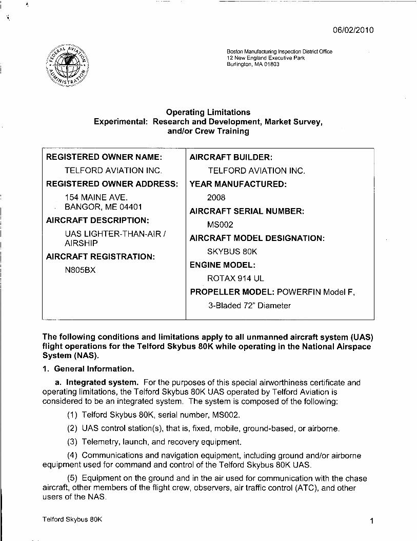
Operating Limitations Experimental: Research and Development, Market Survey,
and/or Crew Training
REGISTERED OWNER NAME:
TELFORD AVIATION INC.
REGISTERED OWNER ADDRESS:
154 MAINE AVE. BANGOR, ME 04401
AIRCRAFT DESCRIPTION:
UAS LIGHTER-THAN-AIR/ AIRSHIP
AIRCRAFT REGISTRATION:
N805BX
AIRCRAFT BUILDER:
TELFORD AVIATION INC.
YEAR MANUFACTURED:
2008 AIRCRAFT SERIAL NUMBER:
MS002
AIRCRAFT MODEL DESIGNATION:
SKYBUS 80K
ENGINE MODEL:
ROTAX 914 UL
PROPELLER MODEL: POWERFIN Model F,
3-Bladed 72" Diameter
The following conditions and limitations apply to all unmanned aircraft system (UAS) flight operations for the Telford Skybus 80K while operating in the National Airspace System (NAS).
1. General Information.
a. Integrated system. For the purposes of this special airworthiness certificate and operating limitations, the Telford Skybus 80K UAS operated by Telford Aviation is considered to be an integrated system. The system is composed of the following:
(1) Telford Skybus 80K, serial number, MS002.
(2) UAS control station(s), that is, fixed, mobile, ground-based, or airborne.
(3) Telemetry, launch, and recovery equipment.
(4) Communications and navigation equipment, including ground and/or airborne equipment used for command and control of the Telford Skybus 80K UAS.
(5) Equipment on the ground and in the air used for communication with the chase aircraft, other members of the flight crew, observers, air traffic control (ATC), and other users of the NAS.
Telford Skybus 80K 1
0 6 / 0 2 / 2 0 1 0
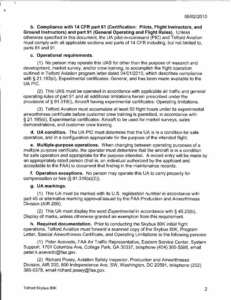
b. Compliance with 14 CFR part 61 (Certification: Pilots, Flight Instructors, and Ground Instructors) and part 91 (General Operating and Flight Rules). Unless otherwise specified in this document, the UA pilot-in-command (PIC) and Telford Aviation must comply with all applicable sections and parts of 14 CFR including, but not limited to, parts 61 and 91.
c. Operational requirements.
(1) No person may operate this UAS for other than the purpose of research and development, market survey, and/or crew training, to accomplish the flight operation outlined in Telford Aviation program letter dated 04/01/2010, which describes compliance with § 21.193(d), Experimental certificates: General, and has been made available to the UA PIC.
(2) This UAS must be operated in accordance with applicable air traffic and general operating rules of part 91 and all additional limitations herein prescribed under the provisions of § 91.319(i), Aircraft having experimental certificates: Operating limitations.
(3) Telford Aviation must accumulate at least 50 flight hours under its experimental airworthiness certificate before customer crew training is permitted, in accordance with § 21.195(d), Experimental certificates: Aircraft to be used for market surveys, sales demonstrations, and customer crew training.
d. UA condition. The UA PIC must determine that the UA is in a condition for safe operation, and in a configuration appropriate for the purpose of the intended flight.
e. Multiple-purpose operations. When changing between operating purposes of a multiple purpose certificate, the operator must determine that the aircraft is in a condition for safe operation and appropriate for the purpose intended. A record entry will be made by an appropriately rated person (that is, an individual authorized by the applicant and acceptable to the FAA) to document that finding in the maintenance records.
f. Operation exceptions. No person may operate this UA to carry property for compensation or hire (§ 91.319(a)(2)).
g. UA markings.
(1) This UA must be marked with its U.S. registration number in accordance with part 45 or alternative marking approval issued by the FAA Production and Airworthiness Division (AIR-200).
(2) This UA must display the word Experimental in accordance with § 45.23(b), Display of marks, unless otherwise granted an exemption from this requirement.
h. Required documentation. Prior to conducting the Skybus 80K initial flight operations, Telford Aviation must forward a scanned copy of the Skybus 80K, Program Letter, Special Airworthiness Certificate, and Operating Limitations to the following persons:
(1) Peter Acevedo, FAA Air Traffic Representative, Eastern Service Center, System Support, 1701 Columbia Ave, College Park, GA 30337, telephone (404) 305-5598, email [email protected].
(2) Richard Posey, Aviation Safety Inspector, Production and Airworthiness Division, AIR 200, 800 Independence Ave, SW, Washington, DC 20591, telephone (202) 385-6378, email [email protected].
Telford Skybus 80K 2

0 6 / 0 2 / 2 0 1 0
i. Change in registrant address. Section 47.45, Change of address, requires that the FAA Aircraft Registry be notified within 30 days of any change in the aircraft registrant's address. Such notification is to be made by providing AC Form 8050-1, Aircraft Registration Application, to the FAA Aircraft Registration Branch (AFS-750) in Oklahoma City, Oklahoma.
j. Certificate display and manual availability. The airworthiness and registration certificates must be displayed, and the aircraft flight manual must be available to the pilot, as prescribed by the applicable sections of 14 CFR, or as prescribed by an exemption granted in accordance with 14 CFR part 11, General Rulemaking Procedures, to Telford Aviation.
2. Program Letter. The Telford Skybus 80K UAS program letter, dated 04/01/2010, will be used as a basis for determining the operating limitations prescribed in this document. All flight operations must be conducted in accordance with the provisions of this document.
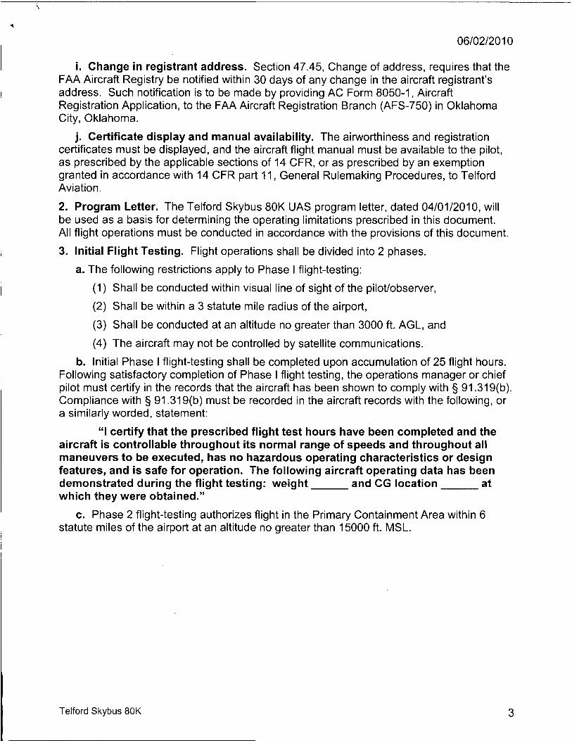
3. Initial Flight Testing. Flight operations shall be divided into 2 phases.
a. The following restrictions apply to Phase I flight-testing:
(1) Shall be conducted within visual line of sight of the pilot/observer,
(2) Shall be within a 3 statute mile radius of the airport,
(3) Shall be conducted at an altitude no greater than 3000 ft. AGL, and
(4) The aircraft may not be controlled by satellite communications.
b. Initial Phase I flight-testing shall be completed upon accumulation of 25 flight hours. Following satisfactory completion of Phase I flight testing, the operations manager or chief pilot must certify in the records that the aircraft has been shown to comply with § 91.319(b). Compliance with § 91.319(b) must be recorded in the aircraft records with the following, or a similarly worded, statement:
"I certify that the prescribed flight test hours have been completed and the aircraft is controllable throughout its normal range of speeds and throughout all maneuvers to be executed, has no hazardous operating characteristics or design features, and is safe for operation. The following aircraft operating data has been demonstrated during the flight testing: weight and CG location at which they were obtained."
c. Phase 2 flight-testing authorizes flight in the Primary Containment Area within 6 statute miles of the airport at an altitude no greater than 15000 ft. MSL.
Telford Skybus 80K 3

0 6 / 0 2 / 2 0 1 0
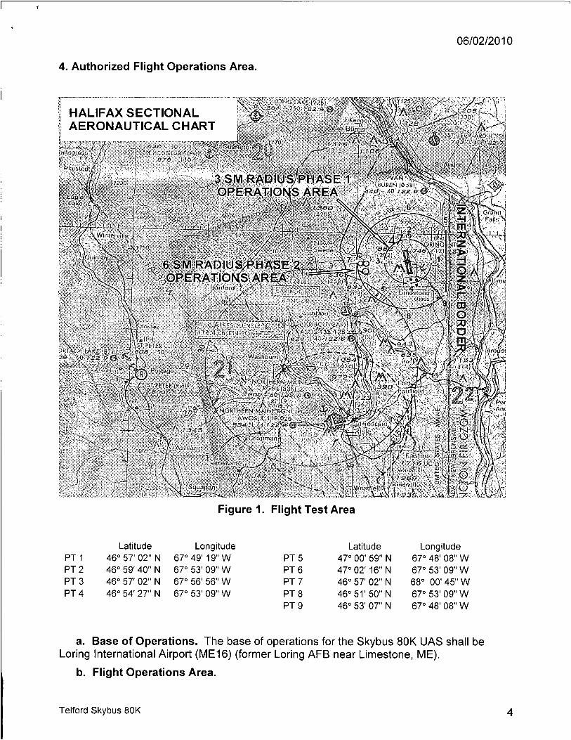
4. Authorized Flight Operations Area.
HALIFAX S E C T I O N A L A E R O N A U T I C A L CHART
Jalidgreai', ! { î» ' ' j
OMO ((<•
s y-m - h o
tONC Uhi i'/2f
" ( 3 I S )
\ . >> * 3 S M RADILI OPERAT
' y t 3 B O V J 1 , 6 '
vï»0 6 SM/RADIU
^ ' o p e r a t ì o K S ARÈÂY«« ' 4 : - V
' L Ai ' « A I A X i i ¿f^^'nc^fi ix . . \ . ...y . Z2.Ü
'[1 • ' /• » Ù-i'Cl Vf v/;COS-l'3B.1 / JW.lf-vt; ! , '—-¿F— ¿..¡loZf- *l 40 ¡22 - Ur pere« o/ \ x ~~ 1 A9Z
ì ' - ' J eoa - w , - / <*>h*>. \ ' N H - ~ J V 3Rf«Gt WK.E iifTBJ <-J eoe - m - , O S v 5 0 ~ f s i 9 0 } \ , - f >
" ^ Ì Ì p o ^ ^
r y- \ , r ? ° ><?,* , - , r - ; ¿ è a © , „ ì^fe^r»'' ' ^ o r J Ä ^ I ^ 9 7 2
Ä •.-•I » /a-;»
* '|N.O«tH£l!N MAINf RGNl (POI) ,t ' AWOS.3' lîa'Q25 . ,
• \ \ b s m n ^
• \ ' W D
Squapan
Figure 1. Flight Test Area
Latitude Longitude Latitude Longitude PT 1 46° 57' 02" N 67° 49' 19" W PT 5 47° 00' 59" N 67° 48' 08" W PT 2 46° 59' 40" N 67° 53' 09" W PT 6 47° 02' 16" N 67° 53' 09" W PT 3 46° 57' 02" N 67° 56' 56" W PT 7 46° 57' 02" N 68° 00' 45" W PT 4 46° 54' 27" N 67° 53' 09" W PT 8 46° 51' 50" N 67° 53' 09" W
PT 9 46° 53' 07" N 67° 48' 08" W
a. Base of Operations. The base of operations for the Skybus 80K UAS shall be Loring International Airport (ME16) (former Loring AFB near Limestone, ME).
b. Flight Operations Area.
Telford Skybus 80K 11

0 6 / 0 2 / 2 0 1 0
(1) The flight test operations area authorized for the UA is graphically depicted in Figure 1. This area shall be referred to as the "Primary Containment Area." Telford Aviation may be permitted to operate within restricted airspace per authorization of the using agency. Under these circumstances, should the UA venture beyond the boundaries of restricted airspace (e.g., spill out), provisions of this experimental certificate shall apply, including authorization to only operate within the boundaries of the Primary Containment Area. In these circumstances, Telford Aviation is responsible for notifying the FAA of the breach of any operations. The Skybus 80K is required to be operated in accordance with the conditions defined in these limitations and in compliance with FAA rules and regulations while operating in restricted airspace.
(2) Flight operations in the Primary Containment Area shall be conducted below 15,000 ft MSL within the boundaries defined. When operating in a terminal environment, the UA must have line of sight communications.
c. Authorized flight times and conditions. All flight operations must be conducted during daylight hours under visual flight rules (VFR).
d. Criteria for remaining in the flight test area. The UAS PIC must ensure all UA flight operations remain within the lateral and vertical boundaries of the flight test area. Furthermore, the UAS PIC must take into account all factors that may affect the capability of the UA to remain within the flight test area. This includes, but is not limited to, considerations for wind, gross weight, and glide distances.
e. Incident, accident, or occurrence reporting. Any incident, accident, or occurrence must be reported to the FAA within 24 hours. This information must be reported to the FAA Communications Center at 781-238-7000 and the Unmanned Aircraft Program Office, AFS-407. AFS-407 can be reached by telephone at 202-385-4636 and fax at 202-385-4651. Any flight operation that transgresses the lateral or vertical boundaries of the flight test area or any restricted airspace must be reported to AFS-407. Accidents must be reported to the National Transportation Safety Board (NTSB) per instructions contained on the NTSB Web site: www.ntsb.gov. If any of the above referenced events occur, further flight operations must not be conducted until reviewed by AFS-407, and authorization to resume operations is provided to Telford Aviation.
5. UA Pilots and Observers.
a. UA PIC roles and responsibilities.
(1) The UA PIC must perform crew duties for only one UA at a time.
(2) All flight operations must have a designated UA PIC. The UA PIC has responsibility over each flight conducted and is accountable for the UA flight operation.
(3) The UA PIC is responsible for the safety of the UA as well as persons and property along the UA flight path. This includes, but is not limited to, collision avoidance and the safety of persons and property in the air and on the ground.
(4) The UA PIC must avoid densely populated areas (§ 91.319) and exercise increased vigilance when operating within or in the vicinity of published airway boundaries.
Telford Skybus 80K 5

0 6 / 0 2 / 2 0 1 0
b. UA PIC certification and ratings requirements.
(1) UA pilots shall hold, at a minimum, an FAA Private Pilot certificate, instrument rating, lighter-than-air category with airship class rating, single or multiengine ratings, and have it in their possession.
(2) The UA PIC must have and be in possession of a valid second-class (or higher) airman medical certificate issued under 14 CFR part 67, Medical Standards and Certification.
c. UA PIC currency, flight review, and training.
(1) No person may act as pilot in command of an unmanned aircraft unless that person has made at least three takeoffs and three landings in manned aircraft within the preceding 90 days acting as the sole manipulator of the flight controls.
(2) The UA PIC must have a flight review in manned aircraft every 24 calendar months in accordance with § 61.56, Flight review.
(3) The UA PIC must maintain currency in unmanned aircraft in accordance with Telford Aviation company procedures.
(4) The UA PIC must have a flight review in unmanned aircraft every 24 calendar months in accordance with Telford Aviation procedures.
(5) All UA PICs must have successfully completed applicable Telford Aviation company training for the UAS.
d. Supplemental UA pilot roles and responsibilities.
(1) Any additional UA pilot(s) assigned to a crew station during UA flight operations will be considered a supplemental UA pilot.
(2) A supplemental UA pilot assists the PIC in the operation of the UA and may do so at the same or a different control station as the PIC. The UA PIC will have operational override capability over any supplemental UA pilots, regardless of position.
(3) A supplemental UA pilot must perform crew duties for only one UA at a time.
e. Supplemental UA pilot certification. The supplemental UA PIC need not be a certificated pilot, but must have successfully completed a recognized private pilot ground school program and pass the written exam. The written exam is valid for 24 months.
f. Supplemental UA pilot currency, flight review, and training.
(1) All UA pilots must maintain currency in unmanned aircraft in accordance with Telford Aviation company procedures.
(2) All UA pilots must have a flight review in unmanned aircraft every 24 calendar months in accordance with Telford Aviation procedures.
(3) All UA pilots must have successfully completed applicable Telford Aviation company training for the UAS.
Telford Skybus 80K 6

0 6 / 0 2 / 2 0 1 0
g. Observer roles and responsibilities. The task of the observer is to provide the UA PIC with instructions to maneuver the UA clear of any potential collision with other traffic. To satisfy these requirements Telford Aviation shall accomplish the following:
(1) Utilize at least 2 observers for all flight operations to be positioned in such a manner as to have a 360 degree field of view.
(2) The observer must perform crew duties for only one UA at a time.
(3) At no time will the observer permit the UA to operate beyond the line-of-sight necessary to ensure maneuvering information can be reliably determined.
(4) At no time will the observer conduct his/her duties more than 3 statute miles laterally or 3000 ft. vertically from the UA.
(5) An observer must maintain continuous visual contact with the UA to discern UA attitude and trajectory in relation to conflicting traffic.
(6) An observer may be positioned in a chase aircraft. When a chase aircraft is used, it must maintain a reasonable proximity, and must position itself relative to the UA to reduce the hazard of collision in accordance with §91.111, Operating near other aircraft. When the observer is located in a chase aircraft, the observer's duties must be dedicated to the task of observation only. Concurrent duty as pilot of the chase aircraft is not authorized.
(7) Observers must continually scan the airspace for other aircraft that pose a potential conflict.
(8) All flight operations conducted in the flight test area must have observers to perform traffic avoidance and visual observation to fulfill the see-and-avoid requirement of § 91.113, Right-of-way rules: Except water operations.
h. Observer certification.
(1) All observers must either hold, at a minimum, an FAA private pilot license or military equivalent, or must have successfully completed specific observer training acceptable to the FAA. An observer does not require currency as a pilot.
(2) All observers must have in their possession a valid second-class (or higher) airman medical certificate issued under part 67.
i. Observer training.
(1) All observers must be thoroughly trained, be familiar with, and possess operational experience with the equipment being used. Such training is necessary for observation and detection of other aircraft for collision avoidance purposes as outlined in the Telford Aviation program letter.
(2) All observers must have successfully completed applicable Telford Aviation company training for the UAS.
6. Equipage.
a. The UAS must be equipped with an operable Mode C transponder and two-way communications equipment allowing communications between the UA pilot, chase aircraft, observers, all UAS control stations, and ATC.
Telford Skybus 80K 7
0 6 / 0 2 / 2 0 1 0
b. The UA and chase aircraft must be equipped with operable navigation, position, and/or strobe/anti-collision lights. Strobe/anti-collision lights must be illuminated during all operations.
7. Communications.
a. Before UA flights.
(1 ) Before conducting operations, the frequency spectrum used for operation and control of the UA must be approved by the Federal Communications Commission or other appropriate government oversight agency.
(2) At least 2 hours before each UA flight, Telford Aviation must contact the local Air Route Traffic Control Center (ARTCC) to obtain a transponder code. Upon initial contact with ATC, the UA PIC must indicate the experimental nature in accordance with § 91.319.
b. During UA flights.
(1 ) Appropriate air traffic frequencies must be monitored during flight operations.
(2) All UA crew positions must maintain two-way communications with each other during all operations. If unable to maintain two-way communication, the UA PIC will expeditiously return the UA to its base of operations while remaining within the flight test area and conclude the flight operation.
8. Flight Conditions.
a. Daylight operations. All flight operations must be conducted during daylight hours in visual meteorological conditions (VMC), including cloud clearance minimums as specified in § 91.155, Basic VFR weather minimums. Flight operation in instrument meteorological conditions (IMC) is not permitted.
b. Prohibitions.
(1) The UA is prohibited from aerobatic flight, that is, an intentional maneuver involving an abrupt change in the UA's attitude, an abnormal acceleration, or other flight action not necessary for normal flight. (See § 91.303, Aerobatic flight.)
(2) Flight operations must not involve carrying hazardous material or the dropping of any objects or external stores, excluding water ballast.
(3) No individual control station may be used to operate more than one UA at one time.
c. Transponder requirements.
(1 ) The UA must operate an approved Mode C altitude encoding transponder during all flight operations.
(2) Chase aircraft transponders must be on standby while performing chase operations flight with the UA.
d. Transponder failure.
(1 ) In the event of transponder failure on either the UA or the chase aircraft, the UA must conclude all flight operations and expeditiously return to its base of operations within the prescribed limitations of this authorization.
Telford Skybus 80K 8
0 6 / 0 2 / 2 0 1 0
(2) In the event of UA transponder failure, a chase aircraft will operate its transponder in Mode C.
e. Notice to airman. Telford Aviation must request the issuance of a Notice to Airman (NOTAM) through the local Automated Flight Service Station at least 24 hours before flight operation.
9. Flight Termination and Lost Link Procedures.
a. Flight termination. In accordance with Telford Aviation program letter, dated 04/01/10, flight must be discontinued at any point that safe operation of the UA cannot be maintained or if hazard to persons or property is imminent.
b. Lost link procedures. In the event of lost link, the UA must provide a means of automatic recovery that ensures airborne operations are predictable and that the UA remains within the flight test area. The chase aircraft or observer, all other UAS control stations, and the appropriate ATC facility will be immediately notified of the lost link condition and the expected UA response.
10. Maintenance and Inspection.
a. General requirements. The UAS must not be operated unless it is inspected and maintained in accordance with the Skybus 80K Maintenance Manual, Document # SKYBUS 02-080-02-0004 dated 20090326[RI>IIi and Skybus 80K GCS Maintenance Procedures, Document # SKYBUS 02-080-02-0012 dated 20090326, or later accepted FAA revision. Telford Aviation must establish and maintain aircraft maintenance records (see paragraph 10(d) below).
b. Inspections. No person may operate this UAS within the preceding 12 calendar months unless it has had a condition inspection performed according to the FAA-accepted Telford Aviation Maintenance and Inspection Program. The UAS must also have been found to be in a condition for safe operation. This inspection will be recorded in the UAS maintenance records as described in paragraph 10(d) below.
c. Authorized inspectors. Only those individuals trained and authorized by Telford Aviation and acceptable to the FAA may perform maintenance and inspections required by these operating limitations.
d. Maintenance and inspection records. Maintenance and inspections of the UAS must be recorded in the UAS maintenance records. The following information must be recorded:
(1) Maintenance record entries must include a description of the work performed, the date of completion for the work, the UAS's total time-in-service, and the name and signature of the person performing the work.
(2) Inspection entries must contain the following, or a similarly worded, statement: I certify that this UAS was inspected on (date), in accordance with the scope and detail of the (applicant name) Inspection and Maintenance Program, and was found to be in a condition for safe operation.
(3) UAS instruments and equipment required to be installed must be inspected and maintained in accordance with the requirements of the Telford Aviation Maintenance and Inspection Program. Any maintenance or inspection of this equipment must be recorded in the UAS maintenance records.
Telford Skybus 80K 9

0 6 / 0 2 / 2 0 1 0
(4) No person may operate this UAS unless the altimeter system and transponder have been tested within the preceding 24 calendar months in accordance with § 91.413, ATC transponder tests and inspections. These inspections will be recorded in the UAS maintenance records.
11. Information Reporting. Telford Aviation will provide the following information to [email protected] a monthly basis. A copy of the report will be provided to AIR-200.
a. Number of flights conducted under this certificate.
b. Pilot duty time per flight.
c. Unusual equipment malfunctions (hardware or software).
d. Deviations from ATC instructions.
e. Unintended entry into lost link flight mode that results in a course change.
12. Revisions and Other Provisions.
a. Experimental certificates, program letters, and operating limitations. The experimental certificate, FAA-accepted Telford Aviation program letter, and operating limitations cannot be reissued, renewed, or revised without application being made to the Boston manufacturing inspection district office (MIDO), in coordination with AIR-200. AIR-200 will be responsible for FAA Headquarters internal coordination with the Aircraft Certification Service, Flight Standards Service, Air Traffic Organization, Office of the Chief Council, and Office of Rulemaking.
b. Certificates of waiver or authorization. The Production and Airworthiness Division, AIR-200 and the Boston MIDO shall be notified immediately if there is any plan for requesting a Certificate of Authorization or Waiver (COA) for UAS operations during the time period the Experimental Certificate is in effect. If the aircraft is authorized to operate under a COA, Telford Aviation must determine that the aircraft is in a condition for safe operation and appropriately configured for the purpose intended. A record entry will be made by an appropriately rated person to document that finding in the aircraft logbook.
c. Amendments and cancellations. The provisions and limitations annotated in this operational approval may be amended or cancelled at any time as deemed necessary by the FAA.
d. Reviews of revisions. All revisions to Telford Aviation FAA-accepted Maintenance and Inspection Program must be reviewed and accepted by the Portland Flight Standards District Office (FSDO).
13. UAS Modifications.
a. Software and system changes. All software and system changes will be documented as part of the normal maintenance procedures and will be available for inspection. All software and system changes must be inspected and approved per Telford Aviation Maintenance and Inspection Program. All software changes to the aircraft and control station are categorized as major changes, and must be provided in summary form at the time they are incorporated.
b. Major modifications. All major modifications, whether performed under the experimental certificate, COA, or other authorizations, that could potentially affect the safe
Telford Skybus 80K 1 0
0 6 / 0 2 / 2 0 1 0
operation of the system, must be documented and provided to the FAA before operating the aircraft under this certificate. Major modifications incorporated under COA or other authorization needs to be provided only if the aircraft is flown under these authorizations during the effective period of the experimental certificate.
c. Submission of modifications. All information requested must be provided to AIR-200, the Boston MIDO, the Portland FSDO, as applicable.
End of Limitations
Aviation Safety Inspector Boston Manufacturing Inspection District Office 12 New England Executive Park Burlington, MA 01803
I certify that I have read and understand the operating limitations and conditions that are a part of the special airworthiness certificate, FAA Form 8130-7, issued on 06/02/2010 for the purposes of research and development, market survey, and/or crew training.
This special airworthiness certificate is issued for Telford Skybus 80K UA, serial ation number N805BX. This certificate expires on 06/01/2011.
Date:
App l ica^s ignatuné) / Jq
Name (Printed): Robert Ziegelaar
Date:
Title: Skybus Program Manager
Company: Telford Aviation
Telford Skybus 80K 1 1

1. (a) DEFINE THE EXPERIMENTAL PURPOSE(S) UNDER WHICH THE AIRCRAFT IS TO BE OPERATED (14 CFR § 21.191).
(a) Research and Development
(b) Market Survey
(c) Crew Training and Proficiency - Pilot Crew and Ground Crew
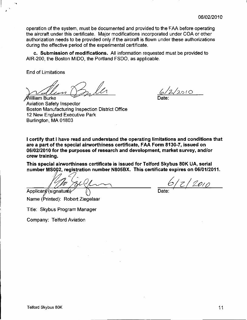
1. (b) DESCRIBE THE PURPOSE/SCOPE OF THE EXPERIMENTAL PROGRAM FOR EACH 14 CFR § 21.191 EXPERIMENTAL PURPOSE SOUGHT (14 CFR §§ 21.193(b)(d)).
SAIC 80K AIRSHIP ENVELOPE GENERAL ASSEMBLY SHOWING IMPORTANT INTERFACE REFERENCES
8AIC BOK AIRSHIP ENVELOPE GENERAL ASSEMBLY SAJC 80K AS - 57-001
Three View GA of the SKYBUS 80K Airship
SKYBUS 80K PROGRAM LETTER ISSUE (C) 20100401- Page 2 of 29
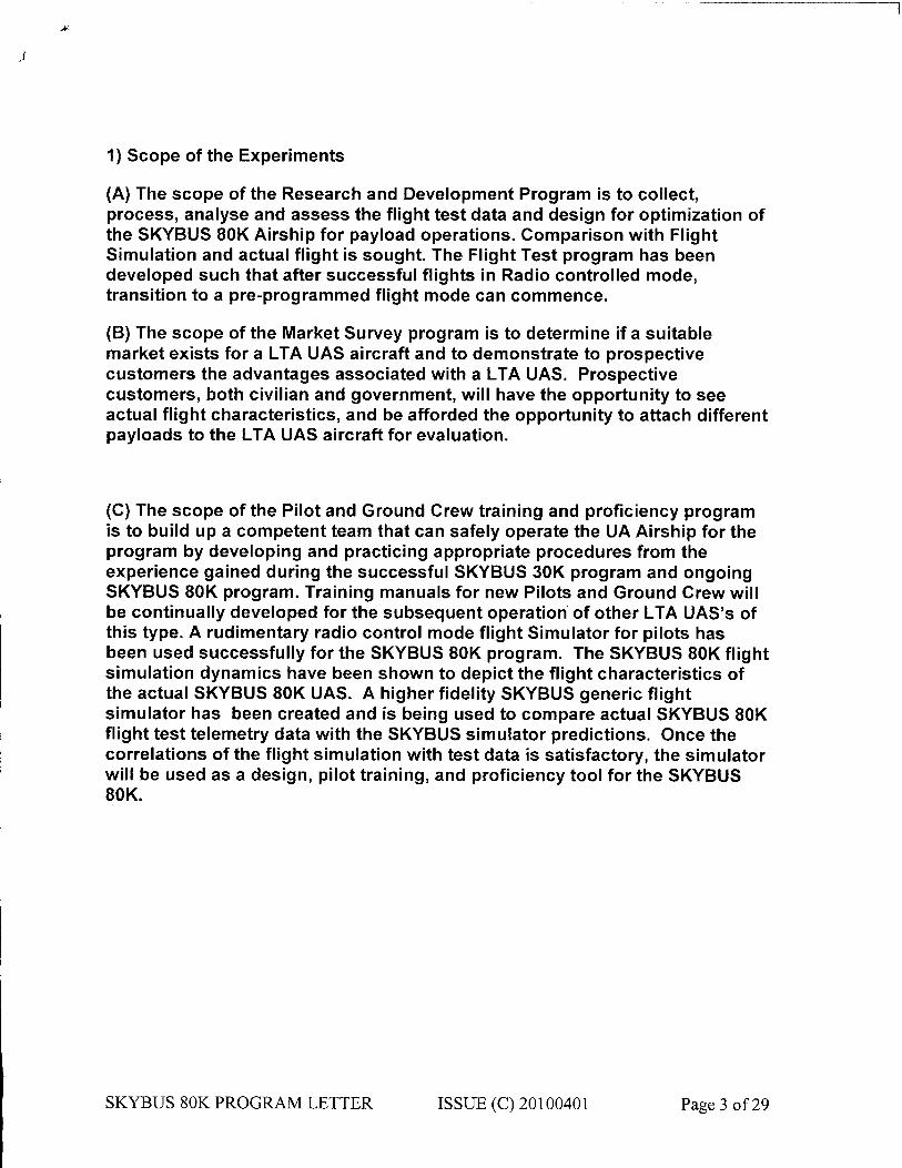
1) Scope of the Experiments
(A) The scope of the Research and Development Program is to collect, process, analyse and assess the flight test data and design for optimization of the SKYBUS 80K Airship for payload operations. Comparison with Flight Simulation and actual flight is sought. The Flight Test program has been developed such that after successful flights in Radio controlled mode, transition to a pre-programmed flight mode can commence.
(B) The scope of the Market Survey program is to determine if a suitable market exists for a LTA UAS aircraft and to demonstrate to prospective customers the advantages associated with a LTA UAS. Prospective customers, both civilian and government, will have the opportunity to see actual flight characteristics, and be afforded the opportunity to attach different payloads to the LTA UAS aircraft for evaluation.
(C) The scope of the Pilot and Ground Crew training and proficiency program is to build up a competent team that can safely operate the UA Airship for the program by developing and practicing appropriate procedures from the experience gained during the successful SKYBUS 30K program and ongoing SKYBUS 80K program. Training manuals for new Pilots and Ground Crew will be continually developed for the subsequent operation of other LTA UAS's of this type. A rudimentary radio control mode flight Simulator for pilots has been used successfully for the SKYBUS 80K program. The SKYBUS 80K flight simulation dynamics have been shown to depict the flight characteristics of the actual SKYBUS 80K UAS. A higher fidelity SKYBUS generic flight simulator has been created and is being used to compare actual SKYBUS 80K flight test telemetry data with the SKYBUS simulator predictions. Once the correlations of the flight simulation with test data is satisfactory, the simulator will be used as a design, pilot training, and proficiency tool for the SKYBUS 80K.
SKYBUS 80K PROGRAM LETTER ISSUE (C) 20100401- Page 3 of 29
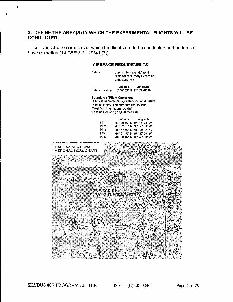
2. DEFINE THE AREA(S) IN WHICH THE EXPERIMENTAL FLIGHTS WILL BE CONDUCTED.
a. Describe the areas over which the flights are to be conducted and address of base operation (14 CFR § 21.193(d)(3)).
AIRSPACE REQUIREMENTS Datum: Loring International Airport
Midpoint of Runway Centerline Limestone, ME
Latitude Longitude Datum Location: 46° 57' 02" N 67° 53' 09" W
Boundary of Flight Operations 6SM Radius Semi Circle, center located at Datum (East boundary is North/South line 1/2 mile West from international border) Up to and including 15,000 feet AGL
Latitude Longitude PT1 47° 00" 59" N 67° 48'08" W PT2 47° 02 16" N 67° 53' 09" W PT 3 46° 57 02" N 68° 00' 45" W PT4 46° 51'50" N 67° 53'09" W PT5 46° 53' 07" N 67° 48'08" W
H A L I F A X S E C T I O N A L A E R O N A U T I C A L C H A R T
\ < f ÌO' -K;¡V.- f J M S ' a •O
A ilVì! I
jM m: h Lrt, V llfÄfc
• ; ^ k w
SKYBUS 80K PROGRAM LETTER ISSUE (C) 20100401- Page 4 of 29
b. Identify all proposed flight areas using latitude and longitude on aeronautical maps.
See previous item, 2(a).
c. Include information on airspeed, altitude, number of flight hours, number of flights and program duration for each test flight area.
There are nine proposed phases to the continued R&D flight test program:
Phase 1: Shakedown and familiarization - up to 3000 ft AGL (COMPLETED)
Phase 1 ensures that the pilot has the correct feel for the flight characteristics of the UAS before attempting specific performance maneuvers. Telemetry data will be interrogated and analyzed post flight before the next flight is permitted to commence. Any safety issues arising from the analyzed telemetry data must be resolved prior to the next flight. The pilot shall be made aware of the results from the telemetry data so that enhancements in control and operations can be potentially realized. The ground crew including observers will be enhancing their basic skills learnt from the SKYBUS 80K ground taxi operations in addition to the skills developed by the SKYBUS 30K program on N305BX. All Phase 1 flight testing will be conducted within the area described in Section 2(a) above. All flights in this phase will be conducted VFR at or below 3000ft AGL.A Maximum static heaviness of 500lb shall be the limit of heaviness for this phase of testing. It is not intended to fly the UAS in a statically light configuration during Phase 1. The minimum heaviness shall not be less than 100 lbs.
Phase 2: UAS flight performance - up to 3000 ft AGL (COMPLETED)
Phase 2 of the R&D flight test program will identify the flight characteristics of the UAS. During this phase the Crew will be further enhancing their skill sets in operating the UAS. It is intended to conduct all tests in this phase at or below 3000 ft AGL within a 6 mile radius of the centre of the main runway in the eastern segment. Speeds up to the maximum possible (circa 50kts) at full throttle will be conducted. On average each flight test is expected to take an hour from Take-Off to touchdown.
SKYBUS 80K PROGRAM LETTER ISSUE (C) 20100401- Page 5 of 29
A Maximum static heaviness of 6001b and a minimum static heaviness of 1001b are the expected operational norms and hence for flight test purposes the limits shall be investigated up to 20% in excess of the expected operational norms.
Flight tests conducted at the various heaviness/lightness configurations shall include; Climb/descent performance, straight and level and turn performance, acceleration I deceleration tests.
It is anticipated that to cover all aspects of this phase of the flight test program , approximately 10 flight hours will have been accumulated.
Phase 3: UAS flight performance - from 3000-8000 ft AGL (COMPLETED)
Phase 3 will build on the flight characteristics established in the previous phases and begin to evaluate the performance characteristics of the UAS at altitudes up to 8000 ft AGL. These flights will be conducted at static heaviness of not less than 0 lbs up to 600 lbs, and perhaps to 20% in excess of expected norms if handling and performance characteristics demonstrated show that it is safe to do so.
Phase 4: Advanced UAS flight performance & basic autopilot shakedown - up to 3000 ft AGL (COMPLETED)
Phase 4 flights will be conducted to provide for a shakedown of basic autopilot functions such as altitude, heading, and airspeed hold. Maximum duration of flights during this phase will be from 30 minutes to several hours, however always during VFR conditions and daylight hours. The maximum altitude for these tests will be up to 3000 ft AGL. These tests will permit the fine tuning of the autopilot and the GCS.
Phase 5: Pre-programmed flight evaluation, pressure height tests - up to 12,000 ft AGL. Advanced crew training
Phase 5 will determine the flight characteristics of the UAS up to it's maximum altitude of 12,000 ft AGL with 500 lbs of dummy payload. Longer duration pre-programmed flights will be conducted during this phase at various static heavinesses and e.g. positions to further evaluate the flight characteristics of the system over it's operating envelope. Any fine tuning of the UAS to further refine it's flight algorithms throughout it's flight envelope will be performed as warranted by the flight test data collected during this phase of flight.
SKYBUS 80K PROGRAM LETTER ISSUE (C) 20100401- Page 6 of 29
»
i
This phase will also be used to further develop pilot and crew skills to enhance the quality of both training and operating procedures and manuals
Phase 6: 24 hour flight test demonstration (multiple daytime missions totaling 24 hours), up to 10,000 ft AGL, with a 500 lb mock payload
Phase 6 will consist of a series of flights building up from the longest flight conducted in the previous phases to ultimately an endurance target of 24 hours. Clearly daytime VFR flights could not be conducted on such continuous flights, therefore recovery of the UAS in the evening, and redeployment of the UAS during the early morning of the next consecutive day will be necessary, weather permitting. No servicing of the UAS, other than what is required to ensure safety, will be permitted in order to simulate a continuous 24 hour period.
The culmination of the flight test program is intended to demonstrate that the UAS can be controlled and operate safely for a 24 hour pre-programmed flight period at an altitude of 10,000 ft with a mock payload of 500 lbs. The demonstration period will encompass more than one day due to the restriction of VFR daytime flight for the UAS,
Phase 7: Increase available payload power - 3000 ft and below
Phase 7 will consist of the addition of a second alternator to further increase available 28V power for potential payload applications. The current 28V alternator provides 130 amps of power, and the second alternator will double this capacity. Ground engine runs will be performed to evaluate the mounting, overall system performance, and any potential electromagnetic interference issues. Functional check flights of no more than 2 hours will be performed following the ground testing to ensure the system performs within normal operational parameters
Phase 8: Preprogrammed Takeoff and Landing under autopilot control - 3000 ft AGL and below
Phase 8 will consist of developing the capability of the airship to takeoff and land in the fully preprogrammed mode under autopilot control. The piccolo autopilot is capable of, and has demonstrated on several other UA systems, preprogrammed takeoff and landing capabilities. This phase will consist of modifying the current flight control algorithms to
SKYBUS 80K PROGRAM LETTER ISSUE (C) 20100401- Page 7 of 29

>
t
handle such maneuvers. Preprogrammed takeoff testing will begin with a series of ground run taxi tests under autopilot control to evaluate autopilot ground handling characteristics. Following taxi tests, full ground run, takeoff and climbouts will be performed under autopilot control. Preprogrammed landing will consist of originally setting a virtual runway elevation several hundred feet above actual ground level to evaluate the airship's landing pattern, final approach, and flare characteristics down to the virtual runway and adjusting flight control algorithms as necessary. The virtual runway will then be lowered incrementally down to actual ground level. The supplemental pilot will be on the pilot control box at all times to disengage the autopilot and take manual control if necessary at any point during the testing. Approximately 10-15 flight hours are anticipated during this phase.
At no time will the manual controls be left unattended, as this will be a safeguard against any improprieties that may occur during the exercise.
Phase 9: Performance Envelope Expansion - Increase maximum static heaviness - Up to 10,000 ft MSL
During Phases 2-3, flight performance was evaluated at a maximum static heaviness of 600 lbs, and it was found the airship had substantial performance margin available for even higher heavinesses. Phase 9 will consist of incrementally increasing maximum static heaviness up to as much as 1000 lbs. Increases in heaviness will be made in 50 lb increments, and a minimum of 1 hour of flight performance testing will be conducted during each flight to evaluate takeoff, landing, minimum and maximum airspeed, and overall handling qualities performance.
d. What class of airspace will be used?
Loring International Airport is located in Class G airspace (uncontrolled airspace). The SKYBUS 80K operations will be conducted in this Class G airspace, and Class E airspace when above 700 feet AGL up to 15,000 feet AGL.
e. Will minimum fuel requirements of 14 CFR § 91.151 be met?
Yes. All R&D test flights will take-off and land at the same airfield and the Airship will be fuelled equivalent to a minimum total flight test duration plus a one hour reserve at Maximum Continuous Power fuel consumption.
f. Will flight-testing include payload testing?
SKYBUS 80K PROGRAM LETTER ISSUE (C) 20100401- Page 8 of 29

Static weights secured to a suspended payload support structure will be used to simulate various payload weights and payload CG positions. Actual payloads may be flown at a later date, but not before Phase 6 of the program, and only after a complete description of the system is submitted to, and reviewed by, the FAA,
g. What considerations need to be taken with regard to payloads?
Payloads will be secured in such a manner as to ensure no load shifting and to withstand all expected maneuvering and emergency load cases.
SKYBUS 80K PROGRAM LETTER ISSUE (C) 20100401- Page 9 of 29
h. Will the aircraft perform any aerobatic maneuvers?
No. Nor will it be capable of doing so.
i. Flight Conditions (e.g., VFR, IFR, VMS, etc.)
Only daytime VFR up to and including an altitude of 12,000 ft will be conducted.
3. AIRCRAFT CONFIGURATION. Attach three-view drawings or three-view dimensioned photographs of the aircraft (14 CFR § 21.193(b)(4)). Describe Unmanned Aircraft System configuration including ground control station. Include a description of aircraft/system performance characteristics including:
See section (2) of this document for a 3-view dimensioned drawing of the SKYBUS 80K Airship and the accompanying photograph.
a. Wing span Envelope Diameter = 34.7 ft (Volume = 80,600 cuft)
b. Length Envelope Length = 130 ft
c. Powerplant Single engine Rotax 914UL 100hp
Single Engine - Rotax 914UL (Non-Certified), 4-stroke, 4 cylinder horizontally opposed, spark ignition engine with turbocharging and electronic control of boost pressure - push rods, Over Head Valves and one central camshaft. The cylinder heads are liquid cooled whilst the cylinders are ram air cooled. The engine has a dry sump forced lubrication system. Other features include Dual breakerless capacitor discharge ignition, 2 constant depression carburettors, solid state turbo control unit, mechanical fuel pumps, propeller drive via a reduction gear with integrated shock absorber and overload clutch, 12V Electric Start, Integrated AC Generator with External rectifier-regulator (12V 20A DC) and a custom External 24VDC Generator.
Cylinder Bore = 3.13in, Stroke = 2.4in, Displacement = 73.9in3, Compression Ratio 9.0:1
Crankshaft to Propeller shaft reduction ratio = 2.43:1
Propeller: 3-bladed 72" diameter Powerfin Composite construction
ISA Performance: Take Off 5800 rpm 113 hp, Max Continuous Speed 5500 rpm 98.5 hp
d. Max gross take off weight 71501b
SKYBUS 80K PROGRAM LETTER ISSUE (C) 20100401- Page 10 of 29

e. Fuel capacity
80 Gallons internal, 25 Gallons in removable conformai tank
f. Payload capacity 500-1000 lbs
g. Max altitude 11,700 ft
h. Endurance Potential for 11 hours with 0.5 hours reserve based on 6.9gph at 5500rpm Maximum Continuous Power for the 80 gallon fuel tank. At 55% maximum continuous power (3400 rpm) the engine generates 45hp and consumes 4.4 gph giving 17.5 hours endurance with 0.5 hours reserve. At 30% maximum continuous power the fuel burn is 3 gallons per hour at 2500 rpm giving 26.5 hours with 0.5 hours reserve.
i. Max airspeed Estimated to be up to 50 knots. The maximum airspeed attainable is expected to be not less than 40 knots
j. Control/data frequencies 900 MHz and 2.4 GHz
k. Guidance and navigation control VFR RC mode for all R&D flight tests in phases 1 through 3 inclusive. Pre-programmed flight mode and RC mode for all flight tests in phases 4 through 9.
4. INSPECTION AND MAINTENANCE (14 CFR 91.7).
a. Describe the inspection and maintenance program that will be used to maintain the aircraft and related systems (includes ground stations and/or other support systems).
SKYBUS 80K Maintenance Manual Issue A 20080528
Rotax 914 UL engine manufacturers inspection and maintenance program.
DRS Technologies SKYBUS GCS Maintenance Procedures, Document number 9040-00053.
Piccolo User's Guide - A comprehensive and detailed guide of component descriptions, interface guidelines, and system setup information for the Piccolo autopilot system.
Piccolo Preflight Checklist - Lists important preflight checks for the Piccolo autopilot system.
Flight Summary Log Sheet - Used for documenting important pre and post flight information (also in Microsoft Word format)
Using Validate During Preflight - Describes procedures on how to validate current Piccolo parameters against a file of known correct parameters.
SKYBUS 80K PROGRAM LETTER ISSUE (C) 20100401- Page 11 of 29

b. Provide copy of flight manual, if applicable, current weight and balance report, equipment list.
Current flight manual is on file with the FAA
5. PILOT QUALIFICATION (14 CFR §§ 61.3, 61.5).
a. Describe the qualifications for each pilot.
The SKYBUS 80K UAS utilizes the following two classes of Pilots:
• PIC's (Pilot in Command)
• Supplemental Pilots
The following pilots have been trained on the SKYBUS 30K UAS:
Airship Licensed Pilot - Mike Fitzpatrick (Airship Management Services Inc) who has 21,000 hours of Lighter-Than-Air time.. FAA pilot certificate number is: 39266966
Airship Licensed Pilot - Bryant H. Farmer who has 20,000 hours of Lighter-Than-Air time.. FAA pilot certificate number is: 1649544
Airship Licensed Pilot - John R. Crayton who has 14,000 hours of Lighter-Than-Air time.. FAA pilot certificate number is: 1753424
Airship Licensed Pilot - Thomas B. Riley who has 2,400 hours of Lighter-Than-Air time.. FAA pilot certificate number is: 1649973
The following supplemental pilots have been trained on the SKYBUS 30K and 80K UAS:
Steve Ouellette - Telford Aviation supplemental pilot of fixed wing models, trained under John McHugh on the Skyship 600 manned airship, Flight simulator training (Realplanes G3 flight simulator adapted by SAIC as documented in simulator file "SKYBUS 30K Trainer 01.plnG3" dated June 14th
2006 and time stamped 10:01) also Steve has flown the SKYBUS 30K airship for 93+ flight hours and the SKYBUS 80K for 35+ hours and holds a current airman medical certificate, 2nd class, issued under 14 CFR Part 67, and has passed the Private Pilot Written Test.
SKYBUS 80K PROGRAM LETTER ISSUE (C) 20100401- Page 12 of 29
Wallis Collie - SAIC supplemental pilot. Holds FAA Private Pilot License with complex aircraft endorsement. Certificate number is 237314469. 185 hours total time in fixed wing aircraft.
UAS experience includes:
• 25+ hours Supplemental Pilot on SKYBUS 80K
• 13 hours as Supplemental Pilot on SKYBUS 30K UAS
• 50+ hours on SKYBUS 30K UAS simulator
• 30 hours on other various UAS, and an additional 15 hours as a Ground Control Station Operator
• Qualified Mission commander, internal and external pilot for UAV ops while at NAVAIR
b. Pilots must be qualified/certificated in the appropriate type of aircraft, i.e., rotorcraft, powered lift, fixed wing, etc.
Our proposal is to have Mike Fitzpatrick (Licensed Airship Pilot) be with (immediately adjacent to) the supplemental pilot with simulator training who will actually have the command of the flight control box. The supplemental pilot has more experience in flying RC and UAS aircraft than the formally qualified Airship Pilot.
c. Describe internal training program to qualify pilots.
Any Pilot wishing to fly the Airship in RC mode must have completed the Telford Aviation Supplemental Pilot Training program and have completed a minimum of 50 hours flight simulator training on the SKYBUS flight simulator in RC mode from a fixed ground perspective position.
d. Describe the qualifications and training of observers.
All observers will have a valid 2nd class (or higher) airman medical certificate that has been issued under 14 CFR Part 67. All observers will be trained, familiar with, and possess operational experience with the equipment being utilized for observation and detection of other aircraft for collision avoidance purposes.
6. AIRCRAFT REGISTRATION AND MARKING (14 CFR Part 45). All Unmanned Aircraft System (UAS) are required to be registered and identified with the registration number. Aircraft must be marked in accordance with part 45.
The Airship will carry N-Marks in accordance with part 45.
SKYBUS 80K PROGRAM LETTER ISSUE (C) 20100401- Page 8 of 29

7. ATC TRANSPONDER AND ALTITUDE REPORTING SYSTEM EQUIPMENT AND USE (14 CFR § 91.215). Describe the aircraft altitude reporting system.
The SKYBUS 80K is fitted with an ATCRBS Transponder - Mode 3/A, 4096 code with altitude reporting (Mode C). The transponder code cannot though be changed dynamically (that is: whilst the UAS Airship is airborne).
The Picollo autopilot does support the capability for the ground station operator to change modes, transponder ID codes, and initiate the IDENT function from the Ground Station interface as required from the Piccolo Command Center interface, however this capability will not be implemented at this time.
8. METHOD FOR SEE AND AVOID (14 CFR § 91.113a). In what manner, or by what means, will the requirement to "see and avoid" other aircraft be met? What performance will the chase plane have?
The UAS Airship operation shall employ a see-and-avoid capability that achieves an equivalent level of safety, comparable to the see-and-avoid requirements for manned aircraft. See-and-avoid will be accomplished through the use of visual observers. As a minimum there will be sufficient visual observers on the surface to continuously observe the UAS in flight. If there is any possibility the ground visual observers cannot ensure an equivalent level of see-and-avoid safety, a visual observer on board a chase aircraft will be employed to meet the see-and-avoid responsibilities. Visual observers shall maintain direct communication with the SKYBUS 80K UAS Airship Pilot. Visual observers are responsible for seeing other aircraft and providing the SKYBUS 80K UAS pilot with a change of course and/or altitude to prevent a collision. The SKYBUS 80K UAS Airship Pilot and the visual observers shall have no other duties or responsibilities when performing their function and maintaining aviation safety shall be more paramount than achieving mission objectives.
9. SAFETY RISK MANAGEMENT. An applicant must provide a safety checklist that identifies and analyzes the hazards of UAS operations that are described in the program letter. Additional information is available by contacting the FAA ASI.
Refer to enclosed response to Safety Checklist guide issued by FAA in Draft format dated 5/28/2008
SKYBUS 80K PROGRAM LETTER ISSUE (C) 20100401- Page 51 of 29

L
10. SYSTEM CONFIGURATION. Provide a description of aircraft system configuration and all on-board and ground-based equipment.
The UAS system is comprised of the following elements:
1. The Autopilot provides on-board flight controls of the UAS
2. The Operator Interface is a ground based software application that provides the human interface mission controls,
3. The Ground Station provides the hardware/software connections between the operator interface software and the UAS. It manages manual flight control interfaces and multiple radio data links (described in detail under Section 10.7.2.3).
4. An independent flight termination system that includes its own data link to the aircraft, operator interface and UAS elements to allow safe termination of UAS operations.
5. The UAS actuator elements that respond to autopilot commands and moves control surfaces as required to fly the UAS.
6. An envelope pressurization control system
7. The electrical system
8. Data Links located both on the UAS vehicle and at the Ground Station.
9. A complete set of controls and displays for operator and ground crew interfacing with the UAS.
10.The Rotax 914 engine and related systems (described in detail under Section 3.0 Aircraft Configuration)
10.1 Autopilot
The Piccolo autopilot provides a complete integrated avionics system including the core autopilot, flight sensors, navigation, wireless communication and payload interface, all in a small package. Navigation is accomplished by using a GPS to generate position and groundspeed, and then use that information to generate a turn rate command to the autopilot. The navigation algorithm in Piccolo follows the great circle path defined by waypoints in a stored flight plan. The flight plan can be updated while in flight.
SKYBUS 80K PROGRAM LETTER ISSUE (C) 20100401- Page 53 of 29

10.1.1 Sensors Included.
The Piccolo autopilot includes the following elements: • CPU. The heart of Piccolo is the MPC555 microcontroller,an automotive
microcontroller based on the popular PowerPC architecture. The MPC555 marries an array of interfaces to a powerful RISC engine that delivers 40Mhz PowerPC operation, including hardware floating point.
• Inertial sensors. Piccolo autopilots use the Crista IMU sensor head technology developed by Cloud Cap. This 3 axis sensor set provides high bit rate data from three 300 deg/sec rate gyros and three axis of accelerometer data. This measurement set gives the Piccolo avionics the ability to control a wide range of aircraft; and allow installation in any attitude.
• Air data. Piccolo avionics include a dual ported 4 KPa (higher range for faster vehicle applications) dynamic pressure sensor, and a absolute ported 15 PSI barometric pressure sensor, and an air temperature sensor. Together these sensors provide the ability to measure true air speed and altitude. These sensors are used as inputs to airspeed and altitude control loops.
• GPS. Piccolo II includes a 4 Hz uBIox GPS solder down module to provide its basic groundspeed and position. The uBIox is also differential capable and the higher rate update allows it to be used in higher dynamic environments.
10.1.2 Interfaces Provided.
The Piccolo autopilot includes the following external interfaces:
• A integrated 900 MHz ISM radio datalink provides primary communications with the system ground station.
• Two CAN busses support connection with a wide range of external devices including the CAN based actuators used in the SKYBUS UAS.
• Five serial interfaces that can be used for payload pass-through ports (up to two pass-through ports), and for interfacing with peripherals like airborne transponders, magnetometers, Iridium modems, etc.
• Sixteen discrete I/O can be used for PWM actuator controls, controls of accessory UAS functions (lights, etc), and can be easily programmed on a case by case basis.
• Four analog inputs (0-5V)
SKYBUS 80K PROGRAM LETTER ISSUE (C) 20100401- Page 55 of 29

10.2 Operator Interface
The Piccolo Command Center (PCC) software provides the human interface to the UAS controls for all phases of flight planning and operations. The Piccolo User's Guide document provides a comprehensive and detailed guide of the PCC interfaces. Key Features of the PCC include:
• Flight Planning Support
o Waypoint Insertion
o Context Menus for common functions. o Route Copy between aircraft, o Flight Plan upload, drop and drag or keyed o Pre-programmed lost link recovery (not in functioning
Autonomous Mode) • Map Display supports:
o Multiple aircraft on single map.
o 3-D Views. High performance smooth zoom 2D and 3D terrain mapping, easy to use like popular 3D mapping software.
o Terrain database supporting DTED and SRTM.
o Integration with web mapping servers for elevation and imagery.
• Intuitive Primary Flight Display and graphical EFIS and ability to change airspeed, altitude, and heading commands from EFIS display.
• User customizable dockable windows so displayed data can be configured per user requirements.
• Status bar provides high-level alert interface and health displays.
The PCC software runs on a COTS PC, interfacing with the Piccolo Ground Station via a 115.2Kbaud RS-232 interface.
Additional operator interface for the manual pressurization control and engine turbo control unit will be performed by SAIC software running on the COTS PC. All engine parameters and pressurization system parameters will be displayed via the same SAIC user interface.
10.3 Ground Station
The Piccolo ground station provides the interface between the operator interface software PC and the autopilot.
SKYBUS 80K PROGRAM LETTER ISSUE (C) 20100401- Page 57 of 29
11.3.1 Manual Flight Control. The manual flight commands are read from the PWM trainer port outputs of a standard Futaba pilot console, packaged into a manual flight command packet and transmitted over the Piccolo radio link (does not use the Futaba radio link). Manual control is initiated by use of a control switch on the Futaba controller and is the highest priority communication between the GS and the autopilot. If there is a disconnection or some other failure that interrupts the manual controls provided to the GS, the autopilot automatically changes modes to auto-flight mode after a set timeout.
11.3.2 Communication links between the ground station control points and UAS Airship are managed by the Piccolo autopilot on the UAS side and the Piccolo Ground Station on the ground side. This provides the ability to implement multiple parallel communication paths to the UAS where independent links communicate controls to the UAS and all links provide identical status and telemetry data from the UAS:
a) A RF communications link using the 1W radio integrated into the autopilot. For the SKYBUS UAS, the integrated radio link will be a 900 MHz ISM radio. An RS232 connection between the Ground Station and the operator interface PC allows full control of the vehicle and display of telemetry data from the UAS.
b) A second radio link is implemented using a 2.4GHz ISM radio is also implemented between the UAS autopilot and the Ground Station. A separate RS232 connection on the ground provides the user interface connection to this link.
c) The Piccolo system supports implementation of a third link over Iridium satellite communications modems between a third RS232 port on the Ground Station and the UAS.
Additionally, manual flight mode and commands console are transmitted to the UAS over either the first (900 MHz) or second (2.4GHz) links as selected by a switch on the Ground Station enclosure.
10.4 Flight Termination System
The SKYBUS 80K Flight Termination System is covered in Detail under Section 11, "System Safety- Flight Termination and Lost Link".
10.5 UAS Actuators
Pitch control of the LTA UAS Airship is provided by electric actuator driven control surfaces on the horizontal port and starboard stabilizers. Similarly Yaw
SKYBUS 80K PROGRAM LETTER ISSUE (C) 20100401- Page 18 of 29

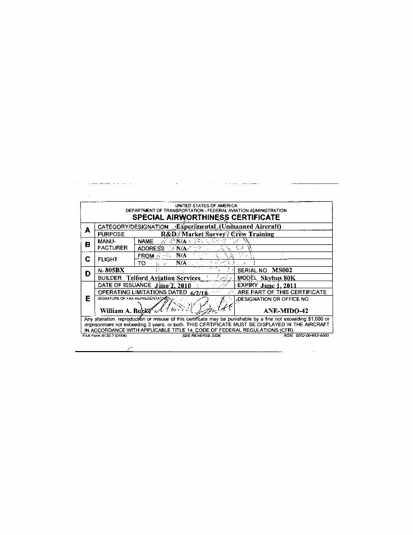
U N I T E D S T A T E S O F A M E R I C A D E P A R T M E N T O F T R A N S P O R T A T I O N - F E D E R A L A V I A T I O N A D M I N I S T R A T I O N
SPECIAL AIRWORTHINESS CERTIFICATE A CATEGORY/DESIGNATION 'Exper imenta l . ( U n m a n n e d A i r c r a f t ) A
PURPOSE R & D : / M a r k e t Survev7 C r e w T r a i n i n g
B MANU- NAME ~N/A - ' ' ' s \ B FACTURER ADDRESS ' N /A \ • \ \
C FLIGHT FROM " N/A C FLIGHT TO N/A j
D N- 8 0 5 B X SERIAL NO. M S 0 0 2 D BUILDER T e l f o r d A v i a t i o n Services * MODEL Skvbus 8 0 K DATE OF ISSUANCE . l ime 2. 2010 EXPIRY June 1 , 2 0 1 1 OPERATING LIMITATIONS DATED fi/2/tft ARE PART OF THIS CERTIFICATE
E SIGNATURE OF FAA REPRESENTATIVES«, ' £ %
W i l l i a m A . B u £ K € t A - t fr- >
. -DESIGNATION OR OFFICE NO. SIGNATURE OF FAA REPRESENTATIVES«, ' £ %
W i l l i a m A . B u £ K € t A - t fr- > A N E - M I D O - 4 2 Any alteration, reproduction or misuse of this certificate may be punishable by a fine not exceeding $1,000 or imprisonment not exceeding 3 years, or both. THIS CERTIFICATE MUST BE DISPLAYED IN THE AIRCRAFT IN ACCORDANCE W I T H APPLICABLE TITLE 14, C O D E OF FEDERAL REGULATIONS (CFR).
FAA Form 8130-7 (07/04) SEE REVERSE SIDE NSN: 0052-00-693-4000
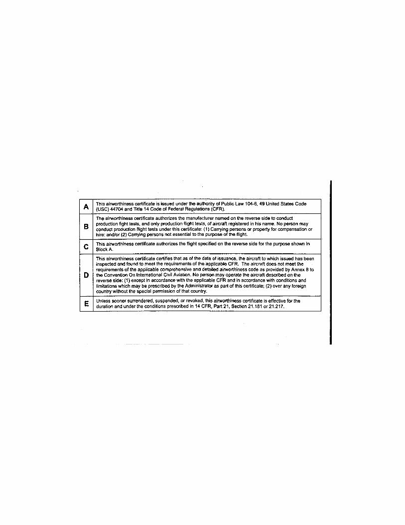
A This airworthiness certificate is issued under the authority of Public Law 104-6, 49 United States Code (USC) 44704 and Title 14 Code of Federal Regulations (CFR).
B The airworthiness certificate authorizes the manufacturer named on the reverse side to conduct production fight tests, and only production flight tests, of aircraft registered in his name. No person may conduct production flight tests under this certificate: (1 ) Carrying persons or property for compensation or hire: and/or (2) Carrying persons not essential to the purpose of the flight.
C This airworthiness certificate authorizes the flight specified on the reverse side for the purpose shown in Block A.
D
This airworthiness certificate certifies that as of the date of issuance, the aircraft to which issued has been inspected and found to meet the requirements of the applicable CFR. The aircraft does not meet the requirements of the applicable comprehensive and detailed airworthiness code as provided by Annex 8 to the Convention On International Civil Aviation. No person may operate the aircraft described on the reverse side: (1) except in accordance with the applicable CFR and in accordance with conditions and limitations which may be prescribed by the Administrator as part of this certificate; (2) over any foreign country without the special permission of that country.
E Unless sooner surrendered, suspended, or revoked, this airworthiness certificate is effective for the duration and under the conditions prescribed in 14 CFR, Part 21, Section 21.181 or 21.217.
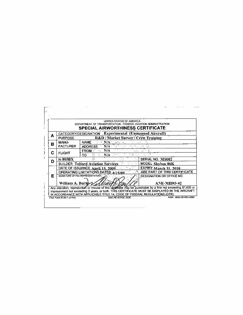
UNITED STATES OF AMERICA DEPARTMENT OF TRANSPORTATION - FEDERAL AVIATION ADMINISTRATION
SPECIAL AIRWORTHINESS CERTIFICATE
A CATEGORY/DESIGNATION Exper imenta l (Unmanned A i r c r a f t ) A PURPOSE R & D / M a r k e t Survey / C r e w T ra in ing
B M A N U -F A C T U R E R
NAME v N/A B M A N U -F A C T U R E R ADDRESS N/A
C F L I G H T F R O M • ' •••- N / A ; ; - */, C F L I G H T T O j: N / A \
D N-805BX SERIAL NO. M S 0 0 2 D BUILDER Te l ford Avia t ion Services MODEL Skvhus 8 0 K
E
D A T E O F I S S U A N C E A n r i l 1 S . 2 0 0 9 EXPIRY M a r r h 7010
E O P E R A T I N G L I M I T A T I O N S D A T E D a/15/OQ A R E P A R T O F T H I S C E R T I F I C A T E
E SIGNATURE OF FAA REPRESENTATIVE^^-;'. ,. . .
W i l l i a m A . B u r l
- D E S I G N A T I O N O R O F F I C E NO.
A N E - M I D O - 4 2 Any alteration, reproduction or misuse of this'c&tiflfcSte may be~punishable by a fine not exceeding $1 ,000 or imprisonment not exceeding 3 years, or both. T H I S C E R T I F I C A T E M U S T BE D I S P L A Y E D IN T H E A I R C R A F T IN A C C O R D A N C E W I T H A P P L I C A B L E T I T L E 14, C O D E O F F E D E R A L R E G U L A T I O N S (CFR) .
FAA Form 8130-7 (07/04) SEE REVERSE SIDE NSN: 0052-00-693-4000
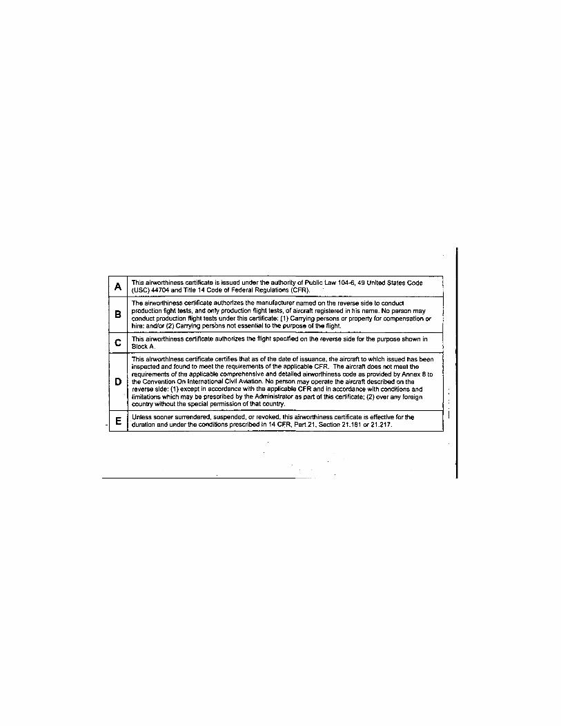
A This airworthiness certificate is issued under the authority of Public Law 104-6, 49 United States Code (USC) 44704 and Title 14 Code of Federal Regulations (CFR).
B The airworthiness certificate authorizes the manufacturer named on the reverse side to conduct production fight tests, and only production flight tests, of aircraft registered in his name. No person may conduct production flight tests under this certificate: (1) Carrying persons or property for compensation or hire: and/or (2) Carrying persons not essential to the purpose of the flight.
C This airworthiness certificate authorizes the flight specified on the reverse side for the purpose shown in Block A.
D
This airworthiness certificate certifies that as of the date of issuance, the aircraft to which issued has been inspected and found to meet the requirements of the applicable CFR. The aircraft does not meet the requirements of the applicable comprehensive and detailed airworthiness code as provided by Annex 8 to the Convention On International Civil Aviation. No person may operate the aircraft described on the reverse side: (1) except in accordance with the applicable CFR and in accordance with conditions and limitations which may be prescribed by the Administrator as part of this certificate; (2) over any foreign country without the special permission of that country.
E Unless sooner surrendered, suspended, or revoked, this airworthiness certificate is effective for the duration and under the conditions prescribed in 14 CFR, Part 21, Section 21.181 or 21.217.
control is provided by an electric actuator driven control surfaces on the lower vertical stabilizer. A 48Vdc supply provides power to the electric actuator motors and a separate 24Vdc supply provides the power for the fail safe brake motor such that in the event of loss of power, the actuators do not back drive. Power is also supplied to proximity limit switches attached to the actuators to prevent bottoming on full extension/retraction. In addition to proximity limit switches, software limits are imposed on the actuators within the proximity limit switches to provide a level of redundancy in the system. Actuator rates and positions are software controlled via the CAN bus interface from the Piccolo Autopilot.
10.6 Envelope Pressurization Control System
The autonomous Envelope Pressurization Control System is a dedicated microcontroller based system designed to maintain air and helium pressure within specified limits of the SKYBUS 80K LTA UAS. The system consists of a Master controller, Display unit, and three sensor units. One sensor unit per ballonet is used to measure the ballonet air pressure in each of the two ballonets, while the third sensor is used to measure helium pressure in the envelope. The Master controller collects the data from the sensor units, and uses a voting scheme to filter the air and helium pressure readings. The Master controller uses the air and helium pressures to provide autonomous control of the ballonet fans. The Master controller communicates with the display unit to provide pressure, and temperature data to the user. 6 switches are provided on the display unit for over-ride control of the 12 relays located in the Master Controller. Each switch may be factory programmed such that they are capable of overriding an individual relay or multiple relays. The SKYBUS 80K LTA UAS utilizes 10 of the 12 Master Controller relays (4 fans (2 per ballonet), 4 air valves (2 per ballonet), and 2 helium valves).
10.7 Electrical System
10.7.1 ELECTRICAL SYSTEM Primary engine system power is 12VDC. The engine's internal AC alternator has a 20 amp capacity. The AC power is converted to DC by a remotely mounted rectifier. A single lead-acid battery is charged by the alternator, and provides approximately 45 minutes of backup power supply if the alternator is off-line. This system provides power for all engine related subsystems including the Starter, Fuel Pumps, Engine Instrumentation System (EIS), and Turbo Control Unit (TCU). It also provides power for the Strobe light and Nav lights, Transponder, Precision Pressure Transducers (PPT), and Control Surface Actuator Limit Switches and Potentiometers. A manually switched contactor disconnects the battery from the 12V power bus, and allows the
SKYBUS 80K PROGRAM LETTER ISSUE (C) 20100401- Page 19 of 29

battery to be charged with the bus offline. An external charge port is provided for charging the 12V battery.
Primary aircraft flight system power is 24VDC. A two (2) 28V electronically controlled alternators, with up to 360 amps combined capacity, is powered via V-belt from a pulley mounted on the prop shaft. Dual 12V lead-acid batteries wired in series are charged by the alternator, and provide approximately 45 minutes of backup power supply if the alternator is off-line. This system provides power for the Avionics Rack, Com & Flight Control Hardware, Flight Sensors, Ballonet Pressurization System, as well as Envelope and Landing lights. Payload power, separate from aircraft bus, is also available from the alternator. A manually switched contactor disconnects the battery from the 28V power and payload buses, and allows the battery to be charged with the bus offline. An external charge port is provided for charging the 24V battery stack.
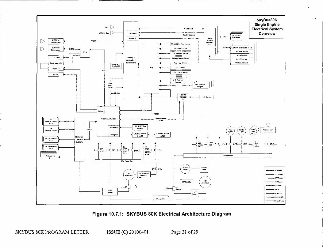
28V and 12V Power is distributed via a circuit breaker panel through shielded wiring. The bus voltages are monitored and relayed to the Ground Station. The external charge port located on the nose of the power car powers the bus and charges the batteries while not in flight. An EU2000i generator rated at 110v and 13.3 amps is used for auxiliary power when the airship is not in proximity to an AC outlet in the hangar. The generator is hung from the power car on the left side, forward. The generator is removed prior to flight.
Figure 10.7.1 shows a diagram of the overall electrical system.
SKYBUS 80K PROGRAM LETTER ISSUE (C) 20100401- Page 20 of 29
SkyBus80K Single Engine
Electrical System Overview
Figure 10.7.1: SKYBUS 80K Electrical Architecture Diagram
SKYBUS 80K PROGRAM LETTER ISSUE (C) 20100401 Page 21 of 29

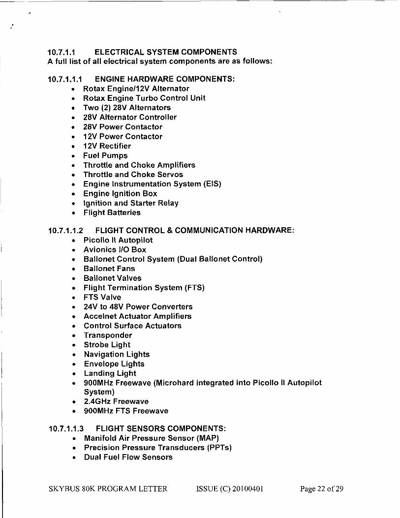
10.7.1.1 ELECTRICAL SYSTEM COMPONENTS A full list of all electrical system components are as follows:
10.7.1.1.1 ENGINE HARDWARE COMPONENTS: • Rotax Engine/12V Alternator • Rotax Engine Turbo Control Unit • Two (2) 28V Alternators • 28V Alternator Controller • 28V Power Contactor • 12V Power Contactor • 12V Rectifier • Fuel Pumps • Throttle and Choke Amplifiers • Throttle and Choke Servos • Engine Instrumentation System (EIS) • Engine Ignition Box • Ignition and Starter Relay • Flight Batteries
10.7.1.1.2 FLIGHT CONTROL & COMMUNICATION HARDWARE: • Picollo II Autopilot • Avionics I/O Box • Ballonet Control System (Dual Ballonet Control) • Ballonet Fans • Ballonet Valves • Flight Termination System (FTS) • FTS Valve • 24V to 48V Power Converters • Accelnet Actuator Amplifiers • Control Surface Actuators • Transponder • Strobe Light • Navigation Lights • Envelope Lights • Landing Light • 900MHz Freewave (Microhard integrated into Picollo II Autopilot
System) • 2.4GHz Freewave • 900MHz FTS Freewave
10.7.1.1.3 FLIGHT SENSORS COMPONENTS: • Manifold Air Pressure Sensor (MAP) • Precision Pressure Transducers (PPTs) • Dual Fuel Flow Sensors
SKYBUS 80K PROGRAM LETTER ISSUE (C) 20100401- Page 22 of 29

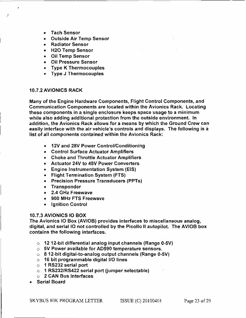
• Tach Sensor • Outside Air Temp Sensor • Radiator Sensor • H20 Temp Sensor • Oil Temp Sensor • Oil Pressure Sensor • Type K Thermocouples • Type J Thermocouples
10.7.2 AVIONICS RACK
Many of the Engine Hardware Components, Flight Control Components, and Communication Components are located within the Avionics Rack. Locating these components in a single enclosure keeps space usage to a minimum while also adding additional protection from the outside environment. In addition, the Avionics Rack allows for a means by which the Ground Crew can easily interface with the air vehicle's controls and displays. The following is a list of all components contained within the Avionics Rack:
• 12V and 28V Power Control/Conditioning • Control Surface Actuator Amplifiers • Choke and Throttle Actuator Amplifiers • Actuator 24V to 48V Power Converters • Engine Instrumentation System (EIS) • Flight Termination System (FTS) • Precision Pressure Transducers (PPTs) • Transponder • 2.4 GHz Freewave • 900 MHz FTS Freewave • Ignition Control
10.7.3 AVIONICS IO BOX The Avionics IO Box (AVIOB) provides interfaces to miscellaneous analog, digital, and serial IO not controlled by the Picollo II autopilot. The AVIOB box contains the following interfaces.
o 12 12-bit differential analog input channels (Range 0-5V) o 5V Power available for AD590 temperature sensors, o 8 12-bit digital-to-analog output channels (Range 0-5V) o 16 bit programmable digital I/O lines o 1 RS232 serial port o 1 RS232/RS422 serial port (jumper selectable) o 2 CAN Bus Interfaces
• Serial Board
SKYBUS 80K PROGRAM LETTER ISSUE (C) 20100401- Page 23 of 29
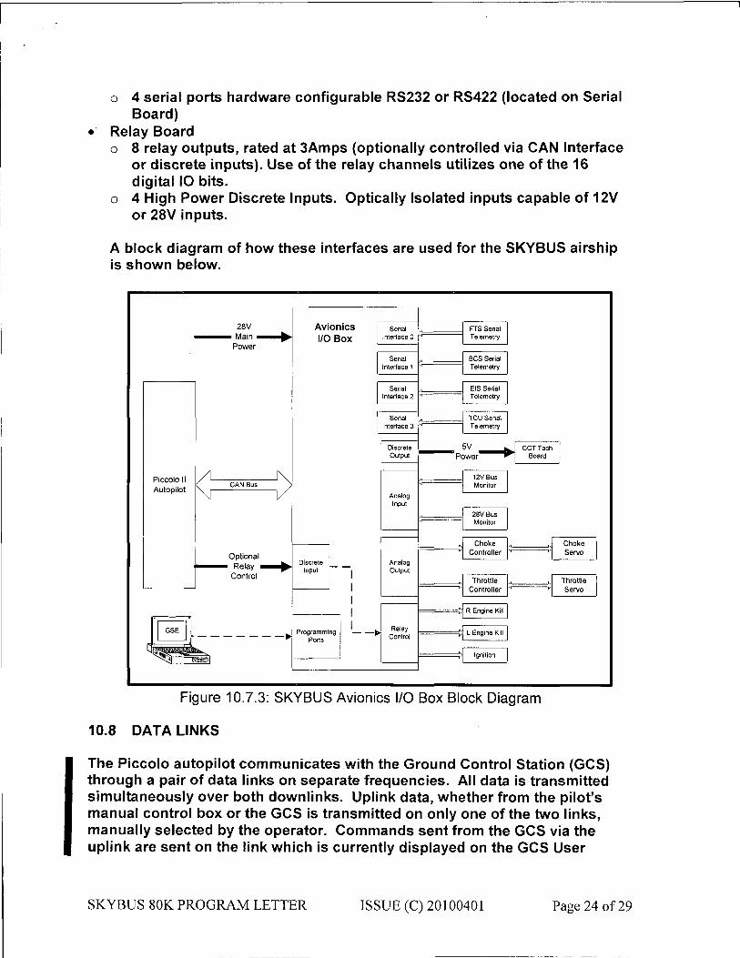
o 4 serial ports hardware configurable RS232 or RS422 (located on Serial Board)
• Relay Board o 8 relay outputs, rated at 3Amps (optionally controlled via CAN Interface
or discrete inputs). Use of the relay channels utilizes one of the 16 digital IO bits.
o 4 High Power Discrete Inputs. Optically Isolated inputs capable of 12V or 28V inputs.
A block diagram of how these interfaces are used for the SKYBUS airship is shown below.
28V • Main •
Power
Piccolo II Autopilot
A
Optional • Relay
Control
Avionics I/O Box
Serial Interface 0
Serial Interface 1
Serial Interface 2
Serial Interface 3
Analog Input
Analog Output
• Relay Control
FTS Serial Telemetry
BCS Serial Telemetry
EIS Serial Telemetry
TCI) Serial Telemetry
L Engine~KiN
Ignition
12V Bus Monitor 12V Bus Monitor
28V Bus Monitor
28V Bus Monitor
Choke Controller
Choke Controller
„ Throttle Controller Throttle
Controller
R Engine Kill
Choke Servo
Throttle Servo
Figure 10.7.3: SKYBUS Avionics I/O Box Block Diagram
10.8 DATA LINKS
The Piccolo autopilot communicates with the Ground Control Station (GCS) through a pair of data links on separate frequencies. All data is transmitted simultaneously over both downlinks. Uplink data, whether from the pilot's manual control box or the GCS is transmitted on only one of the two links, manually selected by the operator. Commands sent from the GCS via the uplink are sent on the link which is currently displayed on the GCS User
SKYBUS 80K PROGRAM LETTER ISSUE (C) 20100401- Page 75 of 29
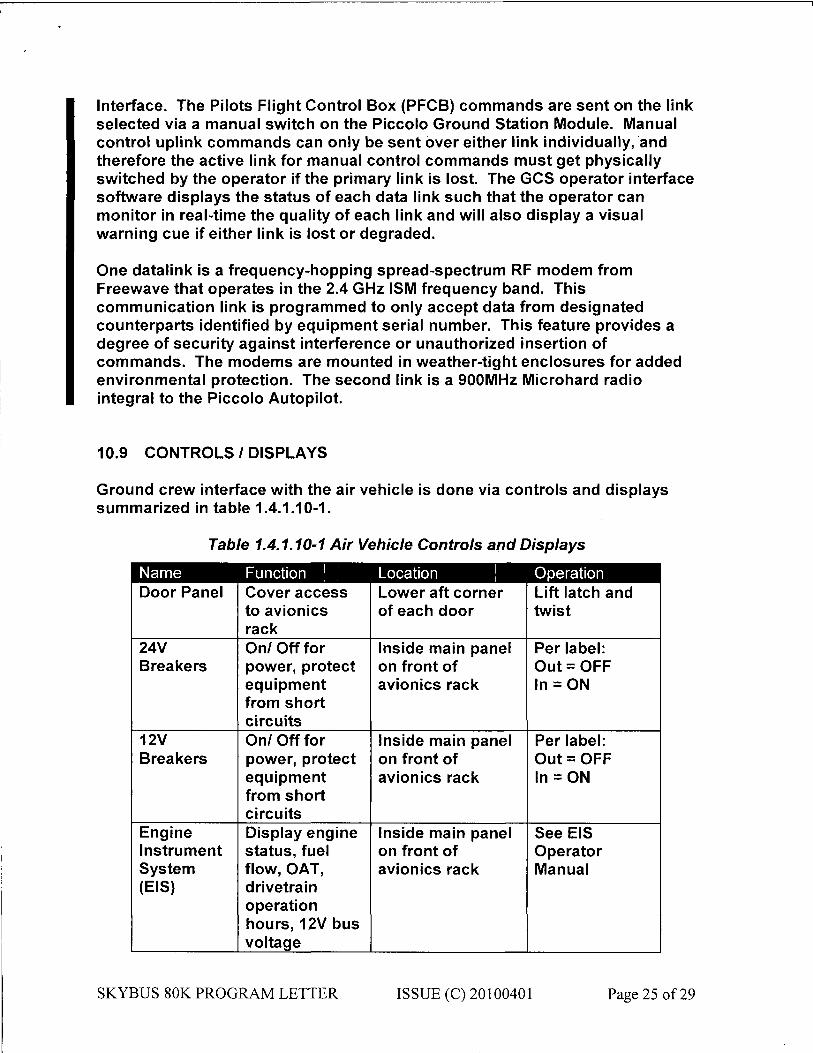
Interface. The Pilots Flight Control Box (PFCB) commands are sent on the link selected via a manual switch on the Piccolo Ground Station Module. Manual control uplink commands can only be sent over either link individually, and therefore the active link for manual control commands must get physically switched by the operator if the primary link is lost. The GCS operator interface software displays the status of each data link such that the operator can monitor in real-time the quality of each link and will also display a visual warning cue if either link is lost or degraded.
One datalink is a frequency-hopping spread-spectrum RF modem from Freewave that operates in the 2.4 GHz ISM frequency band. This communication link is programmed to only accept data from designated counterparts identified by equipment serial number. This feature provides a degree of security against interference or unauthorized insertion of commands. The modems are mounted in weather-tight enclosures for added environmental protection. The second link is a 900MHz Microhard radio integral to the Piccolo Autopilot.
10.9 CONTROLS I DISPLAYS
Ground crew interface with the air vehicle is done via controls and displays summarized in table 1.4.1.10-1.
Table 1.4.1.10-1 Air Vehicle Controls and Displays
Name Function 1 Location Operation Door Panel Cover access Lower aft corner Lift latch and
to avionics of each door twist rack
24V On/ Off for Inside main panel Per label: Breakers power, protect on front of Out = OFF
equipment avionics rack In = ON from short circuits
12V On/ Off for Inside main panel Per label: Breakers power, protect on front of Out = OFF
equipment avionics rack In = ON from short circuits
Engine Display engine Inside main panel See EIS Instrument status, fuel on front of Operator System flow, OAT, avionics rack Manual (EIS) d ri vetrai n
operation hours, 12V bus voltage
SKYBUS 80K PROGRAM LETTER ISSUE (C) 20100401- Page 77 of 29

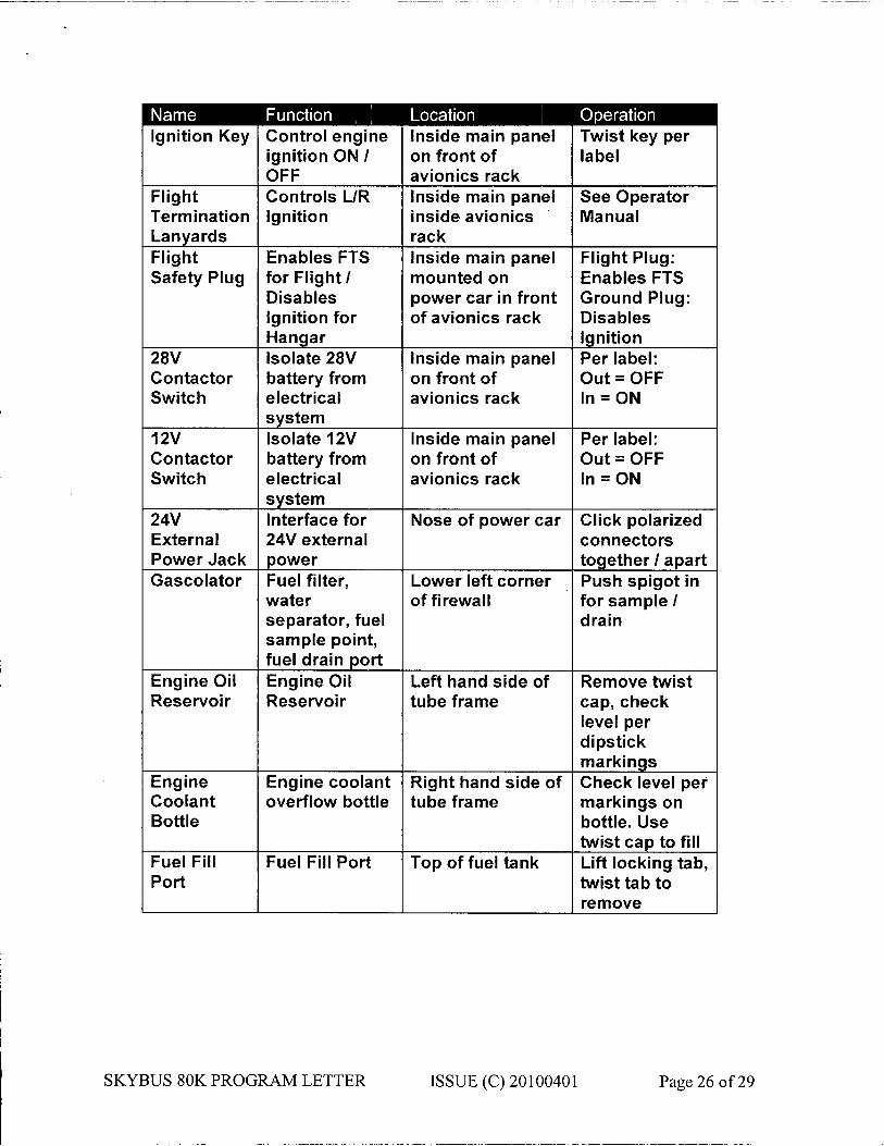
e ai f iTürci i^^^H Location Operation Ignition Key Control engine
ignition ON / OFF
Inside main panel on front of avionics rack
Twist key per label
Flight Termination Lanyards
Controls L/R Ignition
Inside main panel inside avionics rack
See Operator Manual
Flight Safety Plug
Enables FTS for Flight/ Disables Ignition for Hangar
Inside main panel mounted on power car in front of avionics rack
Flight Plug: Enables FTS Ground Plug: Disables Ignition
28V Contactor Switch
Isolate 28V battery from electrical system
Inside main panel on front of avionics rack
Per label: Out = OFF In = ON
12V Contactor Switch
Isolate 12V battery from electrical system
Inside main panel on front of avionics rack
Per label: Out = OFF In = ON
24V External Power Jack
Interface for 24V external power
Nose of power car Click polarized connectors together / apart
Gascolator Fuel filter, water separator, fuel sample point, fuel drain port
Lower left corner of firewall
Push spigot in for sample / drain
Engine Oil Reservoir
Engine Oil Reservoir
Left hand side of tube frame
Remove twist cap, check level per dipstick markings
Engine Coolant Bottle
Engine coolant overflow bottle
Right hand side of tube frame
Check level per markings on bottle. Use twist cap to fill
Fuel Fill Port
Fuel Fill Port Top of fuel tank Lift locking tab, twist tab to remove
SKYBUS 80K PROGRAM LETTER ISSUE (C) 20100401- Page 29 of 29

10.10 Rotax 914 Engine & Related Fuel and Cooling Systems
The Rotax 914 Engine installation and it's related fuel system and coolant system are essentially based on those documented in the Rotax 914UL Manuals. A more detailed description is found in Section 3.0 Aircraft Configuration)
11. SYSTEM SAFETY - FLIGHT TERMINATION AND LOST LINK. What is the expectation of aircraft "Flight" if fuel is starved? Describe/explain aircraft lost link and emergency recovery procedures. Provide an explanation of the flight termination system (FTS) in detail.
The SKYBUS UAS is controlled by the Piccolo autopilot with lost link response logic, and a completely independent Flight Termination system. The flight termination transmitter sends commands from the Ground Station via a 900MHz Freewave Modem to an independent receiver on the air vehicle. Subsequent actions control the FTS Helium Valve and the engine ignition (left and right) via relays, thereby terminating the flight in short order. The FTS is a dedicated microcontroller based system that is isolated from other onboard systems, and has a dedicated back-up power supply.
If fuel is starved the SKYBUS 80K UAS Airship can still be flown real-time by the RC pilot for a period of time as determined by the battery status at the time of the fuel starvation. Unlike conventional heavier than air aircraft the LTA UAS Airship could be in either a statically heavy or statically light condition. If the Airship were statically light then the Airship would rise in altitude rather than descend. In a statically heavy configuration the rate of descent will be proportional to the static heaviness. Contingency planning is accomplished in advance to determine the safest locations to bring the SKYBUS 80K UAS Airship to the surface that is generally uninhabited.
In the event of an emergency the SKYBUS 80K UAS Airship can be brought down like a free balloon into one of the designated areas.
The SKYBUS 80K UAS Airship possesses an independent flight termination system (FTS). The FTS operates on a different frequency than the control data link and has its own redundant battery system. The FTS has been proven on the ground to be effective for a range of 20 miles, which is in excess of the distance the SKYBUS 80K UAS Airship will be flown. The FTS consists of two separate functions the first being to just kill the engine and the second to release the kift gas from the envelope at a controlled rate. If either or both of these functions are activated then the engine can be restarted and or the Flight termination Valve (FTV) can be closed to prevent
SKYBUS 80K PROGRAM LETTER ISSUE (C) 20100401- Page 27 of 29

further lift loss and potentially a full recovery to normal flight could be made.
The protocol for a loss of control link is to shut down the engine first so that it is not running when the SKYBUS 80K UAS Airship reaches the ground, thereby reducing the risk of fire and injury from the propeller to ground personnel. This feature is considered an additional safety benefit that other classes of UAS probably do not have the luxury of since such aircraft effectively are in the position of irrecoverable flight. The Piccolo system can be programmed prior to each mission to ensure that proper action is taken in the event that communications are lost.
Any static heaviness of the SKYBUS 80K UAS Airship at the time of shutting down the engine will permit the SKYBUS 80K UAS Airship to gradually descend. If the rate of descent is too slow or the airship rises due to static lightness the pilot will open the FTS valve which gradually releases helium from the envelope. Once the rate of descent is to the satisfaction of the pilot he can close the FTS valve to arrest the rate of descent or elect to keep it open to increase the rate of descent.
12. COMMAND AND CONTROL. Provide a description of the system and/or procedures for command and control of the UAS.
The command and control aspects of the UAS operations are described in Section 10.1 through 10.5 above.
13. CONTROL STATIONS. Provide a description of the ground/airborne stations used to control the UAS.
Please refer to Section 10.1 Autopilot; Section 10.2 Operator Interface and Section 10.3 Ground Station for a description of the UAS ground/airborne control systems.
SKYBUS 80K PROGRAM LETTER ISSUE (C) 20100401- Page 29 of 29

14. CONTROL FREQUENCIES. Provide a description/listing of the frequencies used to control the UAS.
Communication links between the ground station and UAS Airship are:
a) 1W radio , 900 MHz ISM (frequency hopping) radio internal to autopilot. Is a Microhard Systems Corporation MHX-91 OA radio. DD-1494 information is available.
b) 1W radio , 2.4GHz ISM (frequency hopping) radio external to autopilot (second link). Is a Freewave Corporation radio. DD-1494 information is available.
The Piccolo system supports implementation of a third link over Iridium satellite communications modems between a third RS232 port on the Ground Station and the UAS This function is not used for the SKYBUS 80K UAS
SKYBUS 80K PROGRAM LETTER ISSUE (C) 20100401- Page 29 of 29

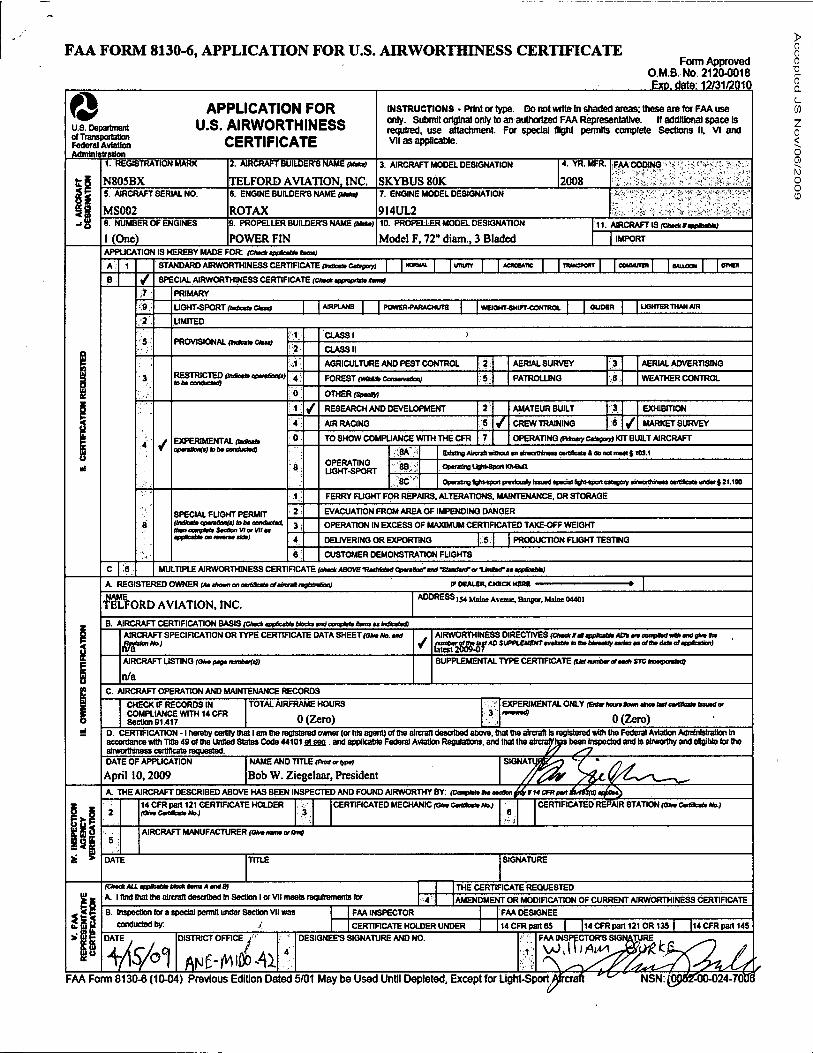
FAA FORM 8130-6, APPLICATION FOR U.S. AIRWORTHINESS CERTIFICATE Form Approved
O.M.B. No. 2120-0018 E x M g t y 12/31/201P,
Ô U.S. Department of Transportation Federal Aviation Administration
APPLICATION FOR U.S. AIRWORTHINESS
CERTIFICATE 1. REGISTRATION MARK
N805BX
2. AIRCRAFT BUILDER'S NAME (Mum
TELFORD AVIATION, INC.
INSTRUCTIONS > Print or type. Do not write In shaded areas; these are for FAA use only. Submit original only to an authorized FAA Representative. If additional space is required, use attachment For special (light permits complete Sections II. VI and VII as applicable.
3. AIRCRAFT MODEL DESIGNATION
SKYBUS 80K
4. YR. MFR.
2008 FAA COOING !
S. AIRCRAFT SERIAL NO.
MS002 8. ENGINE BUILDERS NAME
ROTAX
7. ENGINE MODEL DESIGNATION
914UL2 8. NUMBER OF ENGINES
1 (One) 9. PROPELLER BUILDERS NAME <mta)
POWER FIN 10. PROPELLER MOOEL DESIGNATION
Model F, 72" diaro., 3 Bladcd 11. AIRCRAFT IS (Omk VamfcaUk;
IMPORT APPLICATION IS HEREBY MADE FOR rc»e»<m*ae*ta>>.j
8TANDARD AIRWORTHINESS CERTIFICATE ffnfflba» Cattg»y) | | w o w w . | | unurr | | « o k w i i c | | n w o x m r | | c o u w t p i | | a m o o H | | <
SPECIAL AIRWORTHINESS CERTIFICATE ictm* « x ^ m tamaj
PRIMARY
UGHT-SPORT OnOcmtt CbaaJ O POWER-PARACHUTH WEIGHT-SHIFT-CONTROL UQHTER THAN AIR
LIMITED
PROVISIONAL (todoa» Clual
RESTRICTED | » M i « i M f t n W I d A t eonduclad)
EXPERIMENTAL rxaox» OpMHoAftJ to ò# eondudmQ
8PECIAL FUGHT PERMIT indicate Qpc/i5on/̂ J Is bt ootutucttd,
WorVHaa x * ;
CLASSI
CLASS II
AGRICULTURE AND PEST CONTROL
FOREST (warn ConaafvaSo«)
AERIAL SURVEY
PATROLLING
AERIAL ADVERTISING
WEATHER CONTROL
OTHER (SfcHH
RESEARCH AND DEVELOPMENT
AIR RACING
TO SHOW COMPLIANCE WITH THE CFR 7
OPERATING UGHT-SPORT
;8A
8B
8C
AMATEUR BUILT
CREW TRAINING
EXHIBITION
6 / MARKET SURVEY
OPERATING f F t t w y Ctfsrry) KIT BUILT AIRCRAFT
BiMnjAwiiftwillwul «nttmorthiimsewliBeai* AdonotmMtS t0S.1
Optratíng IjQhVSpoft KtVBuQ
Operating iQhvipat pwdouly Imitd ipwi l 8tf>moitMtnoiyihd)iWHMm<tlcil>yBdtr|i1.H0
FERRY FUGHT FOR REPAIRS. ALTERATIONS. MAINTENANCE, OR STORAGE
EVACUATION FROM AREA OF IMPENDING DANGER
OPERATION IN EXCESS OF MAXIMUM CERTIFICATED TAKE-OFF WEIGHT
DELIVERING OR EXPORTING PRODUCTION FUGHT TESTING
CUSTOMER DEMONSTRATION FLIGHTS
C 1 6 MULTIPLE AIRWORTHINESS CERTIFICATE <*mck ABOVE -Restrict*! Opv&xrmä-Stonatura liaSKrn applicai*;
A. REGISTERED OWNER l*t ¿torn at comb«t» ofetudl nyUuiteg IF DEALER. CHECK HERS
NAME TELFORD AVIATION, INC.
ADDRESS 1J4 Main, Avenue, Bangor. Main 04401
B. AIRCRAFT CERTIFICATION BASIS (CAadiappfceMeMoctaandccngiaiaftroa»tmteaiwg AIRCRAFT SPECIFICATION OR TYPE CERTIFICATE DATA 8HEET (OH No. and AIRWORTHINESS DIRECTIVES (Crw*ta>aspfcaUeAOt^accmptod«»am)¿»aba
SUPPLEUEHTmMtBt m Aa Mwaty aaiiaa aa of Ma data o/«pfcaSo»U
AIRCRAFT LISTING ram paga lunòarfelj
n/a SUPPLEMENTAL TYPE CERTIFICATE tua nmtartf aaoft STO HmvuwM)
C. AIRCRAFT OPERATION AND MAINTENANCE RECORDS CHECK IF RECORDS IN COMPLIANCE WITH 14 CFR 8ectlonS1.417
TOTAL AIRFRAME HOURS
0(Zero) X ]
EXPERIMENTAL ONLY (Btfar Aoure Sown etwa Inf cartBcatebaued or
0(Zero) D. CERTIFICATION -1 hereby certify that I am the registered owner (or Ms agent) of the aircraft described above, that the aircraft Is registered wtth the Federal Aviation Administration m accordance with Title 49 of (he United States Code 44101 et sea . and applicable Federal Aviation Regulations, and that the alrcralYlgra been Inspected and Is airworthy and eligible tor the airworthiness certHlcate requested. DATE OF APPLICATION
April 10,2009 NAME AND TITLE (FKntortypti
Bob W. Ziegelaar, President A. THE AIRCRAFT DESCRIBED ABOVE HAS BEEN INSPECTED AND FOUND AIRWORTHY BY: (CenvUa Oa eetfon
14 CFR part 121 CERTIFICATE HOLDER (OlyCtOkfHo.)
CERTIFICATED MECHANIC <<U~ CerfSbete No.) CERTIFICATED REPAIR 8TATION fa* . CMSoa» Ho.)
AIRCRAFT MANUFACTURER (OtaoamaorOnV
DATE TITLE SIGNATURE
(Chuck ALL aopficai* bkxt fam A and B) A. I tlnd that the alreran described In Section I or VII meets requirements tor
THE CERTIFICATE REQUESTED AMENDMENT OR MODIFICATION OF CURRENT AIRWORTHINESS CERTIFICATE
*ñ B. Inspection tor a special permit under Section VII was conducted by: .1
FAA INSPECTOR
CERTIFICATE HOLDER UNDER
FAA DESIGNEE 14 CFR part 65 I 114 CFR part 121 OR 135 | |14 CFR part 145
DATE DISTRICT OFFICE DESIGNEE'S SIGNATURE AND NO. FAA INSPECTOR'S SIGNATURE
\zJ,H I AW^J&QtfXi
FAA Form 8130-6 (10-04) Previous Edition Dated 5/01 May be Used Until Depleted, Except for Light-Sport

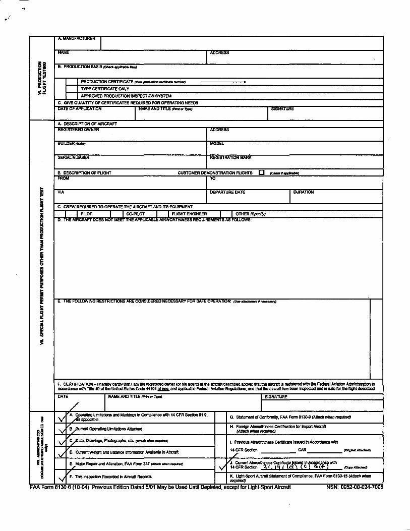

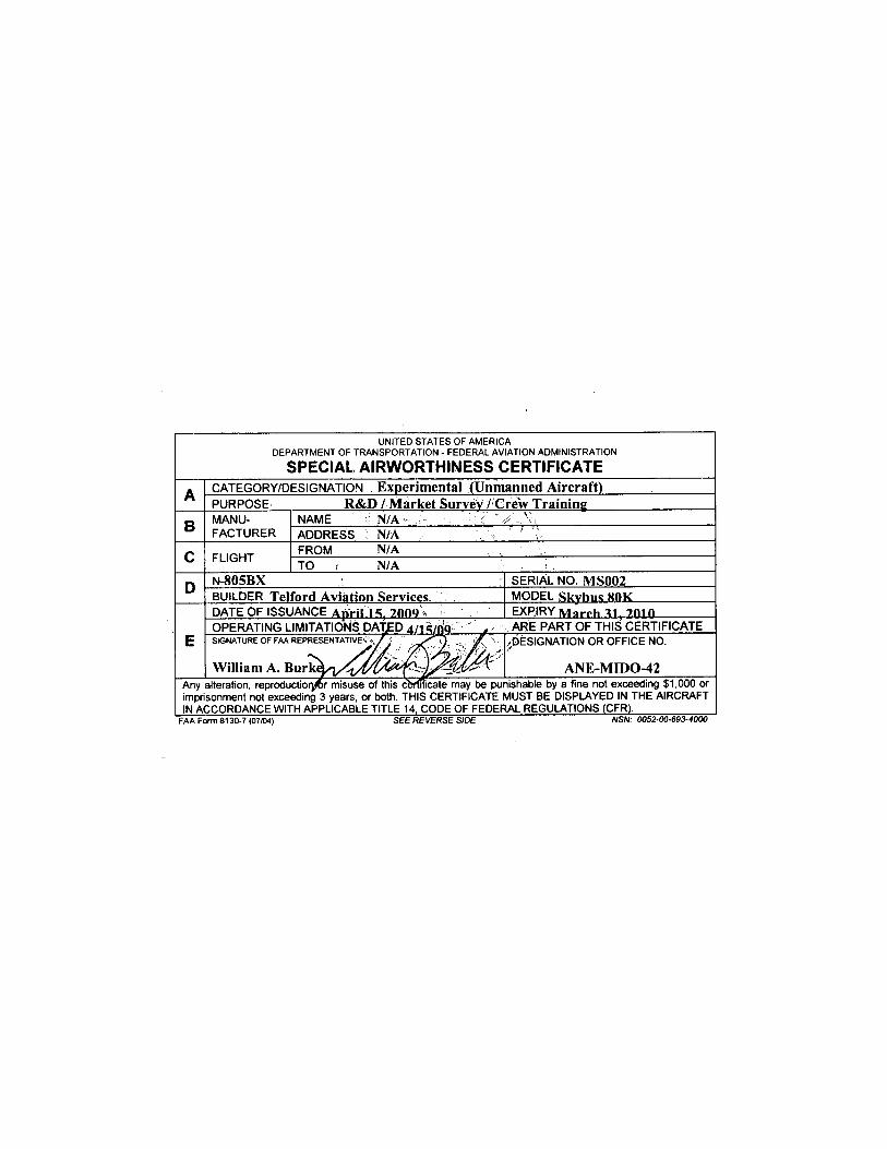
UNITED STATES OF AMERICA DEPARTMENT OF TRANSPORTATION - FEDERAL AVIATION ADMINISTRATION
SPECIAL AIRWORTHINESS CERTIFICATE
A CATEGORY/DESIGNATION Exper imenta l (Unmanned A i r c r a f t ) A PURPOSE R&D / Market Survey / Crew Training
B MANU- NAME ? N/A > /-• ' V, B FACTURER ADDRESS : N/A \ - \ \
C FLIGHT FROM N/A C FLIGHT TO 1 N/A ¡ .
D N-805BX SERIAL NO. M S 0 0 2 D BUILDER Tel ford Aviat ion Services MODEL Skyhns «OK DATE OF ISSUANCE Apr i l IS , 20(19 *. EXPIRY M a r r h 11, 7.010 OPERATING LIMITATIONS DATED 4/1S/QQ , ARE PART OF THIS CERTIFICATE
E SIGNATURE OF FAA REPRESENTATIVE "= f ' /DESIGNATION OR OFFICE NO. s
W i l l i a m A . B u r k ^ ^ x ^ ^ ^ ^ f ^ ^ / 1 ^ ^ ^ ANE-MLDO-42 Any alteration, reproductiory6r misuse of this certificate may be punishable by a fine not exceeding $1,000 or imprisonment not exceeding 3 years, or both. THIS CERTIFICATE MUST BE DISPLAYED IN THE AIRCRAFT IN ACCORDANCE WITH APPLICABLE TITLE 14, CODE OF FEDERAL REGULATIONS (CFR).
FAA Form 8130-7 (07/04) SEE REVERSE SIDE NSN: 0052-00-693-4000
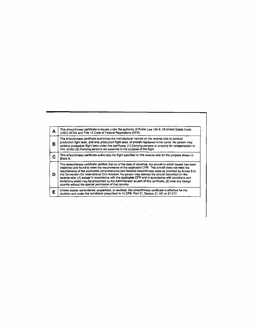
A This airworthiness certifícate is issued under the authority of Public Law 104-6, 49 United States Code (USC) 44704 and Title 14 Code of Federal Regulations (CFR).
B The airworthiness certificate authorizes the manufacturer named on the reverse side to conduct production fight tests, and only production flight tests, of aircraft registered in his name. No person may conduct production flight tests under this certificate: (1 ) Carrying persons or property for compensation or hire: and/or (2) Carrying persons not essential to the purpose of the flight.
C This airworthiness certificate authorizes the flight specified on the reverse side for the purpose shown in Block A.
D
This airworthiness certificate certifies that as of the date of issuance, the aircraft to which issued has been Inspected and found to meet the requirements of the applicable CFR. The aircraft does not meet the requirements of the applicable comprehensive and detailed airworthiness code as provided by Annex 8 to the Convention On International Civil Aviation. No person may operate the aircraft described on the reverse side: (1) except in accordance with the applicable CFR and in accordance with conditions and limitations which may be prescribed by the Administrator as part of this certificate; (2) over any foreign country without the special permission of that country.
E Unless sooner surrendered, suspended, or revoked, this airworthiness certificate is effective for the duration and under the conditions prescribed in 14 CFR, Part 21, Section 21.181 or 21.217.
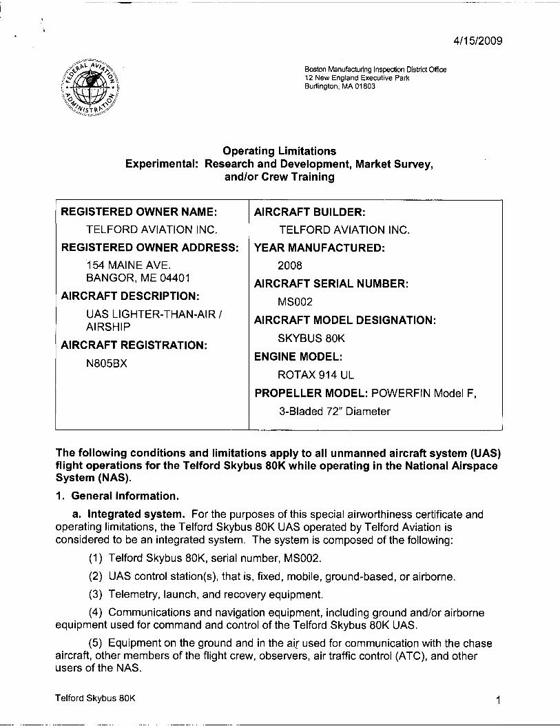
4 / 1 5 / 2 0 0 9
Boston Manufacturing Inspection District Office 12 New England Executive Park Burlington, MA 01803
Operating Limitations Experimental: Research and Development, Market Survey,
and/or Crew Training
REGISTERED OWNER NAME:
TELFORD AVIATION INC.
REGISTERED OWNER ADDRESS:
154 MAINE AVE. BANGOR, ME 04401
AIRCRAFT DESCRIPTION:
UAS LIGHTER-THAN-AIR / AIRSHIP
AIRCRAFT REGISTRATION:
N805BX
AIRCRAFT BUILDER:
TELFORD AVIATION INC.
YEAR MANUFACTURED:
2008 AIRCRAFT SERIAL NUMBER:
MS002
AIRCRAFT MODEL DESIGNATION:
SKYBUS 80K
ENGINE MODEL:
ROTAX 914 UL
PROPELLER MODEL: POWERFIN Model F,
3-Bladed 72" Diameter
The following conditions and limitations apply to all unmanned aircraft system (UAS) flight operations for the Telford Skybus 80K while operating in the National Airspace System (NAS).
1. General Information.
a. Integrated system. For the purposes of this special airworthiness certificate and operating limitations, the Telford Skybus 80K UAS operated by Telford Aviation is considered to be an integrated system. The system is composed of the following:
(1) Telford Skybus 80K, serial number, MS002.
(2) UAS control station(s), that is, fixed, mobile, ground-based, or airborne.
(3) Telemetry, launch, and recovery equipment.
(4) Communications and navigation equipment, including ground and/or airborne equipment used for command and control of the Telford Skybus 80K UAS.
(5) Equipment on the ground and in the air used for communication with the chase aircraft, other members of the flight crew, observers, air traffic control (ATC), and other users of the NAS.
Telford Skybus 80K 10

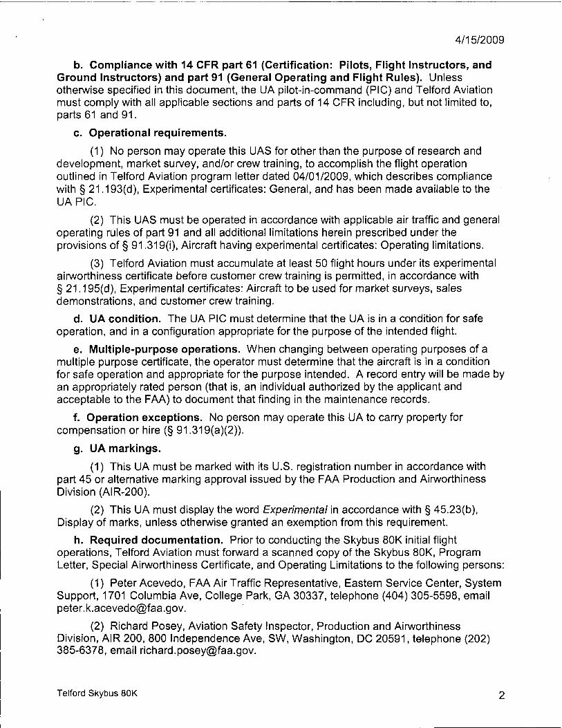
4 / 1 5 / 2 0 0 9
b. Compliance with 14 CFR part 61 (Certification: Pilots, Flight Instructors, and Ground Instructors) and part 91 (General Operating and Flight Rules). Unless otherwise specified in this document, the UA pilot-in-command (PIC) and Telford Aviation must comply with all applicable sections and parts of 14 CFR including, but not limited to, parts 61 and 91.
c. Operational requirements.
(1) No person may operate this UAS for other than the purpose of research and development, market survey, and/or crew training, to accomplish the flight operation outlined in Telford Aviation program letter dated 04/01/2009, which describes compliance with § 21.193(d), Experimental certificates: General, and has been made available to the UA PIC.
(2) This UAS must be operated in accordance with applicable air traffic and general operating rules of part 91 and all additional limitations herein prescribed under the provisions of § 91.319(i), Aircraft having experimental certificates: Operating limitations.
(3) Telford Aviation must accumulate at least 50 flight hours under its experimental airworthiness certificate before customer crew training is permitted, in accordance with § 21.195(d), Experimental certificates: Aircraft to be used for market surveys, sales demonstrations, and customer crew training.
d. UA condition. The UA PIC must determine that the UA is in a condition for safe operation, and in a configuration appropriate for the purpose of the intended flight.
e. Multiple-purpose operations. When changing between operating purposes of a multiple purpose certificate, the operator must determine that the aircraft is in a condition for safe operation and appropriate for the purpose intended. A record entry will be made by an appropriately rated person (that is, an individual authorized by the applicant and acceptable to the FAA) to document that finding in the maintenance records.
f. Operation exceptions. No person may operate this UA to carry property for compensation or hire (§ 91.319(a)(2)).
g. UA markings.
(1) This UA must be marked with its U.S. registration number in accordance with part 45 or alternative marking approval issued by the FAA Production and Airworthiness Division (AIR-200).
(2) This UA must display the word Experimental in accordance with § 45.23(b), Display of marks, unless otherwise granted an exemption from this requirement.
h. Required documentation. Prior to conducting the Skybus 80K initial flight operations, Telford Aviation must forward a scanned copy of the Skybus 80K, Program Letter, Special Airworthiness Certificate, and Operating Limitations to the following persons:
(1) Peter Acevedo, FAA Air Traffic Representative, Eastern Service Center, System Support, 1701 Columbia Ave, College Park, GA 30337, telephone (404) 305-5598, email [email protected].
(2) Richard Posey, Aviation Safety Inspector, Production and Airworthiness Division, AIR 200, 800 Independence Ave, SW, Washington, DC 20591, telephone (202) 385-6378, email [email protected].
Telford Skybus 80K 10

4 / 1 5 / 2 0 0 9
i. Change in registrant address. Section 47.45, Change of address, requires that the FAA Aircraft Registry be notified within 30 days of any change in the aircraft registrant's address. Such notification is to be made by providing AC Form 8050-1, Aircraft Registration Application, to the FAA Aircraft Registration Branch (AFS-750) in Oklahoma City, Oklahoma.
j. Certificate display and manual availability. The airworthiness and registration certificates must be displayed, and the aircraft flight manual must be available to the pilot, as prescribed by the applicable sections of 14 CFR, or as prescribed by an exemption granted in accordance with 14 CFR part 11, General Rulemaking Procedures, to Telford Aviation.
2. Program Letter. The Telford Skybus 80K UAS program letter, dated 04/02/2009, will be used as a basis for determining the operating limitations prescribed in this document. All flight operations must be conducted in accordance with the provisions of this document.
3. Initial Flight Testing. Flight operations shall be divided into 2 phases.
a. The following restrictions apply to Phase I flight-testing:
(1) Shall be conducted within visual line of sight of the pilot/observer,
(2) Shall be within a 3 statute mile radius of the airport,
(3) Shall be conducted at an altitude no greater than 3000 ft. AGL, and
(4) The aircraft may not be controlled by satellite communications.
b. Initial Phase I flight-testing shall be completed upon accumulation of 25 flight hours. Following satisfactory completion of Phase I flight testing, the operations manager or chief pilot must certify in the records that the aircraft has been shown to comply with § 91.319(b). Compliance with § 91.319(b) must be recorded in the aircraft records with the following, or a similarly worded, statement:
"I certify that the prescribed flight test hours have been completed and the aircraft is controllable throughout its normal range of speeds and throughout all maneuvers to be executed, has no hazardous operating characteristics or design features, and is safe for operation. The following aircraft operating data has been demonstrated during the flight testing: weight and CG location at which they were obtained."
c. Phase 2 flight-testing authorizes flight in the Primary Containment Area within 6 statute miles of the airport at an altitude no greater than 15000 ft. MSL.
Telford Skybus 80K 10

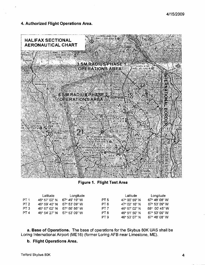
4 / 1 5 / 2 0 0 9
4. Authorized Flight Operations Area.
HALIFAX S E C T I O N A L I A E R O N A U T I C A L C H A R T
Figure 1. Flight Test Area
Latitude Longitude Latitude Longitude PT 1 46° 57' 02" N 67° 49' 19" W PT 5 47° 00' 59" N 67° 48' 08" W PT 2 46° 59' 40" N 67° 53' 09" W PT 6 47° 02' 16" N 67° 53' 09" W PT 3 46° 57' 02" N 67° 56' 56" W PT 7 46° 57' 02" N 68° 00' 45" W PT 4 46° 54' 27" N 67° 53' 09" W PT 8 46° 51'50" N 67° 53' 09" W
PT 9 46° 53' 07" N 67° 48' 08" W
a. Base of Operations. The base of operations for the Skybus 80K UAS shall be Loring International Airport (ME16) (former Loring AFB near Limestone, ME).
b. Flight Operations Area.
Telford Skybus 80K 10

4 / 1 5 / 2 0 0 9
(1) The flight test operations area authorized for the UA is graphically depicted in Figure 1. This area shall be referred to as the "Primary Containment Area." Telford Aviation may be permitted to operate within restricted airspace per authorization of the using agency. Under these circumstances, should the UA venture beyond the boundaries of restricted airspace (e.g., spill out), provisions of this experimental certificate shall apply, including authorization to only operate within the boundaries of the Primary Containment Area. In these circumstances, Telford Aviation is responsible for notifying the FAA of the breach of any operations. The Skybus 80K is required to be operated in accordance with the conditions defined in these limitations and in compliance with FAA rules and regulations while operating in restricted airspace.
(2) Flight operations in the Primary Containment Area shall be conducted below 15,000 ft MSL within the boundaries defined. When operating in a terminal environment, the UA must have line of sight communications.
c. Authorized flight times and conditions. All flight operations must be conducted during daylight hours under visual flight rules (VFR).
d. Criteria for remaining in the flight test area. The UAS PIC must ensure all UA flight operations remain within the lateral and vertical boundaries of the flight test area. Furthermore, the UAS PIC must take into account all factors that may affect the capability of the UA to remain within the flight test area. This includes, but is not limited to, considerations for wind, gross weight, and glide distances.
e. Incident, accident, or occurrence reporting. Any incident, accident, or occurrence must be reported to the FAA within 24 hours. This information must be reported to the FAA Communications Center at 781-238-7000 and the Unmanned Aircraft Program Office, AIR-160. AIR-160 can be reached by telephone at 202-385-4636 and fax at 202-385-4651. Any flight operation that transgresses the lateral or vertical boundaries of the flight test area or any restricted airspace must be reported to AIR-160. Accidents must be reported to the National Transportation Safety Board (NTSB) per instructions contained on the NTSB Web site: www.ntsb.gov. If any of the above referenced events occur, further flight operations must not be conducted until reviewed by AIR-160, and authorization to resume operations is provided to Telford Aviation.
5. UA Pilots and Observers.
a. UA PIC roles and responsibilities.
(1) The UA PIC must perform crew duties for only one UA at a time.
(2) All flight operations must have a designated UA PIC. The UA PIC has responsibility over each flight conducted and is accountable for the UA flight operation.
(3) The UA PIC is responsible for the safety of the UA as well as persons and property along the UA flight path. This includes, but is not limited to, collision avoidance and the safety of persons and property in the air and on the ground.
(4) The UA PIC must avoid densely populated areas (§ 91.319) and exercise increased vigilance when operating within or in the vicinity of published airway boundaries.
Telford Skybus 80K 10

4 / 1 5 / 2 0 0 9
b. UA PIC certification and ratings requirements.
(1) UA pilots shall hold, at a minimum, an FAA Private Pilot certificate, instrument rating, lighter-than-air category with airship class rating, single or multiengine ratings, and have it in their possession.
(2) The UA PIC must have and be in possession of a valid second-class (or higher) airman medical certificate issued under 14 CFR part 67, Medical Standards and Certification.
c. UA PIC currency, flight review, and training.
(1) No person may act as pilot in command of an unmanned aircraft unless that person has made at least three takeoffs and three landings in manned aircraft within the preceding 90 days acting as the sole manipulator of the flight controls.
(2) The UA PIC must have a flight review in manned aircraft every 24 calendar months in accordance with § 61.56, Flight review.
(3) The UA PIC must maintain currency in unmanned aircraft in accordance with Telford Aviation company procedures.
(4) The UA PIC must have a flight review in unmanned aircraft every 24 calendar months in accordance with Telford Aviation procedures.
(5) All UA PICs must have successfully completed applicable Telford Aviation company training for the UAS.
d. Supplemental UA pilot roles and responsibilities.
(1) Any additional UA pilot(s) assigned to a crew station during UA flight operations will be considered a supplemental UA pilot.
(2) A supplemental UA pilot assists the PIC in the operation of the UA and may do so at the same or a different control station as the PIC. The UA PIC will have operational override capability over any supplemental UA pilots, regardless of position.
(3) A supplemental UA pilot must perform crew duties for only one UA at a time.
e. Supplemental UA pilot certification. The supplemental UA PIC need not be a certificated pilot, but must have successfully completed a recognized private pilot ground school program and pass the written exam. The written exam is valid for 24 months.
f. Supplemental UA pilot currency, flight review, and training.
(1) All UA pilots must maintain currency in unmanned aircraft in accordance with Telford Aviation company procedures.
(2) All UA pilots must have a flight review in unmanned aircraft every 24 calendar months in accordance with Telford Aviation procedures.
(3) All UA pilots must have successfully completed applicable Telford Aviation company training for the UAS.
Telford Skybus 80K 10

4 / 1 5 / 2 0 0 9
g. Observer roles and responsibilities. The task of the observer is to provide the UA PIC with instructions to maneuver the UA clear of any potential collision with other traffic. To satisfy these requirements Telford Aviation shall accomplish the following:
(1) Utilize at least 2 observers for all flight operations to be positioned in such a manner as to have a 360 degree field of view.
(2) The observer must perform crew duties for only one UA at a time.
(3) At no time will the observer permit the UA to operate beyond the line-of-sight necessary to ensure maneuvering information can be reliably determined.
(4) At no time will the observer conduct his/her duties more than 3 statute miles laterally or 3000 ft. vertically from the UA.
(5) An observer must maintain continuous visual contact with the UA to discern UA attitude and trajectory in relation to conflicting traffic.
(6) An observer may be positioned in a chase aircraft. When a chase aircraft is used, it must maintain a reasonable proximity, and must position itself relative to the UA to reduce the hazard of collision in accordance with §91.111, Operating near other aircraft. When the observer is located in a chase aircraft, the observer's duties must be dedicated to the task of observation only. Concurrent duty as pilot of the chase aircraft is not authorized.
(7) Observers must continually scan the airspace for other aircraft that pose a potential conflict.
(8) All flight operations conducted in the flight test area must have observers to perform traffic avoidance and visual observation to fulfill the see-and-avoid requirement of §91.113, Right-of-way rules: Except water operations.
h. Observer certification.
(1) All observers must either hold, at a minimum, an FAA private pilot license or military equivalent, or must have successfully completed specific observer training acceptable to the FAA. An observer does not require currency as a pilot.
(2) All observers must have in their possession a valid second-class (or higher) airman medical certificate issued under part 67.
i. Observer training.
(1) All observers must be thoroughly trained, be familiar with, and possess operational experience with the equipment being used. Such training is necessary for observation and detection of other aircraft for collision avoidance purposes as outlined in the Telford Aviation program letter.
(2) All observers must have successfully completed applicable Telford Aviation company training for the UAS.
6. Equipage.
a. The UAS must be equipped with an operable Mode C transponder and two-way communications equipment allowing communications between the UA pilot, chase aircraft, observers, all UAS control stations, and ATC.
Telford Skybus 80K 10

4 / 1 5 / 2 0 0 9
b. The UA and chase aircraft must be equipped with operable navigation, position, and/or strobe/anti-collision lights. Strobe/anti-collision lights must be illuminated during all operations.
7. Communications.
a. Before UA flights.
(1 ) Before conducting operations, the frequency spectrum used for operation and control of the UA must be approved by the Federal Communications Commission or other appropriate government oversight agency.
(2) At least 2 hours before each UA flight, Telford Aviation must contact the local Air Route Traffic Control Center (ARTCC) to obtain a transponder code. Upon initial contact with ATC, the UA PIC must indicate the experimental nature in accordance with § 91.319.
b. During UA flights.
(1 ) Appropriate air traffic frequencies must be monitored during flight operations.
(2) All UA crew positions must maintain two-way communications with each other during all operations. If unable to maintain two-way communication, the UA PIC will expeditiously return the UA to its base of operations while remaining within the flight test area and conclude the flight operation.
8. Flight Conditions.
a. Daylight operations. All flight operations must be conducted during daylight hours in visual meteorological conditions (VMC), including cloud clearance minimums as specified in § 91.155, Basic VFR weather minimums. Flight operation in instrument meteorological conditions (IMC) is not permitted.
b. Prohibitions.
(1) The UA is prohibited from aerobatic flight, that is, an intentional maneuver involving an abrupt change in the UA's attitude, an abnormal acceleration, or other flight action not necessary for normal flight. (See § 91.303, Aerobatic flight.)
(2) Flight operations must not involve carrying hazardous material or the dropping of any objects or external stores, excluding water ballast.
(3) No individual control station may be used to operate more than one UA at one time.
c. Transponder requirements.
(1 ) The UA must operate an approved Mode C altitude encoding transponder during all flight operations.
(2) Chase aircraft transponders must be on standby while performing chase operations flight with the UA.
d. Transponder failure.
(1 ) In the event of transponder failure on either the UA or the chase aircraft, the UA must conclude all flight operations and expeditiously return to its base of operations within the prescribed limitations of this authorization.
Telford Skybus 80K 10

4 / 1 5 / 2 0 0 9
(2) In the event of UA transponder failure, a chase aircraft will operate its transponder in Mode C.
e. Notice to airman. Telford Aviation must request the issuance of a Notice to Airman (NOTAM) through the local Automated Flight Service Station at least 24 hours before flight operation.
9. Flight Termination and Lost Link Procedures.
a. Flight termination. In accordance with Telford Aviation program letter, dated 04/01/09, flight must be discontinued at any point that safe operation of the UA cannot be maintained or if hazard to persons or property is imminent.
b. Lost link procedures. In the event of lost link, the UA must provide a means of automatic recovery that ensures airborne operations are predictable and that the UA remains within the flight test area. The chase aircraft or observer, all other UAS control stations, and the appropriate ATC facility will be immediately notified of the lost link condition and the expected UA response.
10. Maintenance and Inspection.
a. General requirements. The UAS must not be operated unless it is inspected and maintained in accordance with the Skybus 80K Maintenance Manual, Document # SKYBUS 02-080-02-0004 dated 20090326, and Skybus 80K GCS Maintenance Procedures, Document # SKYBUS 02-080-02-0012 dated 20090326, or later accepted FAA revision. Telford Aviation must establish and maintain aircraft maintenance records (see paragraph 10(d) below).
b. Inspections. No person may operate this UAS within the preceding 12 calendar months unless it has had a condition inspection performed according to the FAA-accepted Telford Aviation Maintenance and Inspection Program. The UAS must also have been found to be in a condition for safe operation. This inspection will be recorded in the UAS maintenance records as described in paragraph 10(d) below.
c. Authorized inspectors. Only those individuals trained and authorized by Telford Aviation and acceptable to the FAA may perform maintenance and inspections required by these operating limitations.
d. Maintenance and inspection records. Maintenance and inspections of the UAS must be recorded in the UAS maintenance records. The following information must be recorded:
(1) Maintenance record entries must include a description of the work performed, the date of completion for the work, the UAS's total time-in-service, and the name and signature of the person performing the work.
(2) Inspection entries must contain the following, or a similarly worded, statement: I certify that this UAS was inspected on (date), in accordance with the scope and detail of the (applicant name) Inspection and Maintenance Program, and was found to be in a condition for safe operation.
(3) UAS instruments and equipment required to be installed must be inspected and maintained in accordance with the requirements of the Telford Aviation Maintenance and Inspection Program. Any maintenance or inspection of this equipment must be recorded in the UAS maintenance records.
Telford Skybus 80K 10

4 / 1 5 / 2 0 0 9
(4) No person may operate this UAS unless the altimeter system and transponder have been tested within the preceding 24 calendar months in accordance with § 91.413, ATC transponder tests and inspections. These inspections will be recorded in the UAS maintenance records.
11. Information Reporting. Telford Aviation will provide the following information to [email protected] a monthly basis. A copy of the report will be provided to AIR-200.
a. Number of flights conducted under this certificate.
b. Pilot duty time per flight.
c. Unusual equipment malfunctions (hardware or software).
d. Deviations from ATC instructions.
e. Unintended entry into lost link flight mode that results in a course change.
12. Revisions and Other Provisions.
a. Experimental certificates, program letters, and operating limitations. The experimental certificate, FAA-accepted Telford Aviation program letter, and operating limitations cannot be reissued, renewed, or revised without application being made to the Boston manufacturing inspection district office (MIDO), in coordination with AIR-200. AIR-200 will be responsible for FAA Headquarters internal coordination with the Aircraft Certification Service, Flight Standards Service, Air Traffic Organization, Office of the Chief Council, and Office of Rulemaking.
b. Certificates of waiver or authorization. The Production and Airworthiness Division, AIR-200 and the Boston MIDO shall be notified immediately if there is any plan for requesting a Certificate of Authorization or Waiver (COA) for UAS operations during the time period the Experimental Certificate is in effect. If the aircraft is authorized to operate under a COA, Telford Aviation must determine that the aircraft is in a condition for safe operation and appropriately configured for the purpose intended. A record entry will be made by an appropriately rated person to document that finding in the aircraft logbook.
c. Amendments and cancellations. The provisions and limitations annotated in this operational approval may be amended or cancelled at any time as deemed necessary by the FAA.
d. Reviews of revisions. All revisions to Telford Aviation FAA-accepted Maintenance and Inspection Program must be reviewed and accepted by the Portland Flight Standards District Office (FSDO).
13. UAS Modifications.
a. Software and system changes. All software and system changes will be documented as part of the normal maintenance procedures and will be available for inspection. All software and system changes must be inspected and approved per Telford Aviation Maintenance and Inspection Program. All software changes to the aircraft and control station are categorized as major changes, and must be provided in summary form at the time they are incorporated.
b. Major modifications. All major modifications, whether performed under the experimental certificate, COA, or other authorizations, that could potentially affect the safe
Telford Skybus 80K 1 0

4 / 1 5 / 2 0 0 9
operation of the system, must be documented and provided to the FAA before operating the aircraft under this certificate. Major modifications incorporated under COA or other authorization needs to be provided only if the aircraft is flown under these authorizations during the effective period of the experimental certificate.
c. Submission of modifications. All information requested must be provided to AIR-200, the Boston MIDO, the Portland FSDO, as applicable.
End of Limitations
Aviation Safety Inspector Boston Manufacturing Inspection District Office 12 New England Executive Park Burlington, MA 01803
I certify that I have read and understand the operating limitations and conditions that are a part of the special airworthiness certificate, FAA Form 8130-7, issued on 4/15/2009, for the purposes of research and development, market survey, and/or crew training.
This special airworthiness certificate is issued for Telford Skybus 80K UA, serial number MS002, registration number N805BX.
Date:
Name printed): RoberfZiegelaar
Title: Skybus Program Manager
Company: Telford Aviation
ite:
Telford Skybus 80K 10